Microstructure and Fabrication of Cu-Pb-Sn/Q235 Laminated Composite by Semi-Solid Rolling
by
 ,
,
Yubo Zhang
1,2,* ,
,
Jiaming Liu
1,
Ying Fu
3,
Jinchuan Jie
1,
Yiping Lu
1,
Qingtao Guo
2,
Tongmin Wang
1 and
Tingju Li
1,* 1
Key Laboratory of Solidification Control and Digital Preparation Technology (Liaoning Province), School of Materials Science and Engineering, Dalian University of Technology, Dalian 116024, China
2
State Key Laboratory of Metal Material for Marine Equipment and Application, Anshan 114000, China
3
Engineering Institute, Bohai University, Jinzhou 121001, China
*
Authors to whom correspondence should be addressed.
Metals 2018, 8(9), 722; https://doi.org/10.3390/met8090722
Submission received: 7 August 2018
/
Revised: 31 August 2018
/
Accepted: 12 September 2018
/
Published: 13 September 2018
Abstract
:In the present work, Cu-Pb-Sn and Q235 laminated composite were fabricated by a horizontal semisolid rolling procedure. The interfacial structure, elemental distribution, and properties of the composite were investigated. Finite-element simulation was conducted to analyze the temperature field and solidification process during the semisolid rolling. An appropriate semi-solid region was observed at a pouring temperature of 1598 K in the simulation, which would effectively kept fluidity and avoided casting defects. The experimental results showed that good interface between Cu-Pb-Sn alloy and Q235 steel was achieved by the proposed process at 1598 K, without casting defects or excessive deformation. The Cu and Fe alloys were bonded mainly by the diffusion of Fe into Cu matrix, and a handful of microscopic Pb-rich layer. Fine Pb-rich precipitates were uniformly distributed in the Cu-Pb-Sn alloy, and were considered to be advantageous to the self-lubrication property. The average tensile-shear strength of the interface was higher than 57.68 MPa at a pouring temperature of 1598 K, which fulfilled the requirements for a further extrusion process.
1. Introduction
Bimetallic laminated materials have received a lot of attention as a result of their excellent properties [1,2,3,4,5,6]. Better performance is acquired by the combination of advantages from the component materials. They could be potentially applied in military, automobile, and aerospace industries, to replace some traditional materials. For example, a laminated composite made of Cu and Fe alloys is an ideal material for the bearing bush of an automobile engine. The steel provides the necessary mechanical properties of strength and hardness while the Cu-Pb alloy layer enhances the thermal conductivity and, particularly, abrasion resistance at the surface of the composite. By cladding Cu-Pb alloy onto the steel surface, the composite possesses good comprehensive properties derived from both of them.
Several methods have been used for the fabrication of Cu/Fe laminated materials, such as diffusion bonding [7], rolling bonding [8,9], welding [10], and explosive welding [11], etc. But the improvement is still needed due to low efficiency and the high cost of existing technologies. A good metallurgical bonding at the interface is generally required for laminated materials, which is assured by inter-solubility between the two constituents [12]. However, there is a very low inter-solubility between Cu and Fe alloys in their solid and even in the liquid condition. The Cu-Fe binary alloy is a peritectic system [13], it displays a thermodynamic tendency toward the formation of a miscibility gap [14,15]. When passing through this gap during solidification, the original Cu-Fe liquid decomposes into two distinct immiscible liquids, the Cu-rich phase and Fe-rich phase. They separate and then solidify respectively with the temperature drops. In this case, it is very difficult to achieve a metallurgical bonding between Cu and Fe alloys. The bonding procedure of the Cu/Fe laminated composite remains an enormous challenge.
Another difficulty in the fabrication process is the control of microstructure evolution of the cladding Cu-Pb alloy. The binary Cu-Pb alloy is a typically monotectic alloy, there is also a miscibility gap in the binary Cu-Pb phase diagram. A single Cu-Pb liquid divides into primary Cu phase and Pb-rich liquid when it enters into this gap during the solidification [16,17]. Due to the great discrepancy in the density and melting temperature between Cu and Pb, severe macro-segregation and elemental layering easily happen under the conventional solidification condition. In general, Cu-Pb alloy with homogeneous structure or fibrous arrangement of Pb-rich phases is regarded as a good wear-resistant material [18,19]. In order to improve the alloy self-lubrication and thermostable performance, it is of great importance to achieve uniform microstructure of Cu-Pb-Sn alloy with fine Pb-rich precipitates.
Among the preparation technologies of the Cu/Fe laminated materials, semisolid rolling is an appropriate way for the widespread use. Mechanical pressure introduced by rolling process is beneficial for the bonding between Cu and Fe alloys, while cold rollers contribute to uniform and fine grain structure of Cu-Pb-Sn alloy by increasing the cooling rate. This method provides a beneficial exploration for further continuous production of Cu/Fe laminated materials [20,21].
In this paper, the Cu-12Pb-2Sn alloy and Q235 steel laminated composite was prepared by an optimized horizontal semisolid rolling technology. During the process, Cu-Pb-Sn alloy liquid was poured onto the surface of a preheated Q235 steel plate, and then the laminated composite went through the roller for the bonding. The main purpose of this study was to investigate the evolution of interfacial structure, and to fabricate the Cu-Pb-Sn/Q235 laminated composite with good bonding and uniform solidification structure. Microstructure, compositional distribution, and tensile-shear strength of the interfacial region were also investigated to analyze the bonding mechanism of Cu and Fe alloys.
2. Experimental Procedures
2.1. Materials and Pretreatment
The Cu-Pb-Sn alloy used in the present study was prepared by commercially pure Cu (99.8%), Pb (99.99%) and Sn (99.9%). The commercial Q235 steel sheet of 3 mm thickness (Dalian Lvsang Industry Co. Ltd., Dalian, China) was used as the base material. Their chemical compositions are listed in Table 1, all the compositions quoted are in wt.% unless otherwise stated.
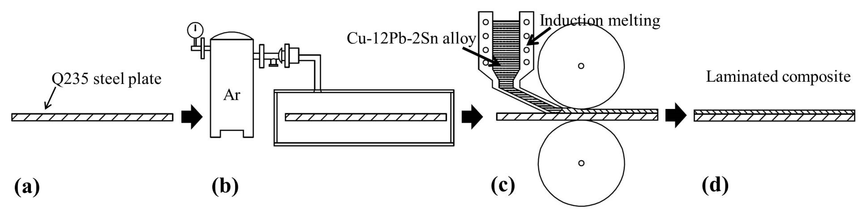
The processing procedures consist of surface treatment, preheating, melting and semisolid rolling as shown in Figure 1. The pretreatments of the steel plate are necessary before bonding. Grinding and polishing were carried out to remove the oxides and degrease the surface. Then the plate was moved into a furnace immediately, and preheated at 573 K for 5 min with Ar gas protection to avoid surface oxidation.
2.2. Semisolid Rolling Fabrication
The laminated composite was prepared by a horizontal semisolid rolling process. First, the Cu-12Pb-2Sn alloy was melted in an induction heating coil at about 1673 K. The melting point of Pb and Sn is 600.5 K and 504.9 K, respectively, which is much lower than the alloy melting temperature. Therefore, the alloy liquid was held for only 5 min to avoid the melting loss of Pb and Sn. At the same time, Q235 steel plate (150 mm × 120 mm × 3 mm) was taken from the furnace and placed in the middle of two rollers. Then the Cu-Pb-Sn liquid was poured onto the plate at desired temperature. The pouring system was improved by designing short runners, which reduced the temperature fluctuations. The pouring gate was designed as a rectangle (80 mm × 3 mm) to obtain uniform temperature distribution and rapid spreading of Cu-Pb-Sn liquid. The solidification started as soon as the liquid spread over the plate, through getting into the semisolid state. The composite plate went through the roller under this condition. The Cu and Fe alloys were bonded under mechanical pressure introduced by the rollers, and the cladding Cu-Pb-Sn alloy was rapidly solidified under the cooling influence. The roller spacing and the diameter of the roll wheel were 6 mm and 250 mm, respectively. The experiments were performed at the rolling speed of 3 rad/min. Different pouring temperatures (1573–1623 K) were used to investigate the appropriate technological parameters.
2.3. Microstructure and Mechanical Properties
After preparation, the laminated composite was cross-cut, then ground and polished for microscopic observation. The interfacial microstructure was investigated by an MEF-4A optical microscope (Leica Microsystems GmbH, Wetzlar, Germany), the phase composition, line element and mapping analysis were confirmed by electron probe microanalyzer (EPMA) JXA-8530F Plus (JEOL, Tokyo, Japan).
In order to evaluate the interfacial strength, the specimens were cut from the laminated material and prepared for tensile-shear test. The tests were performed at room temperature, using a DNS100 universal testing machine (Changchun Research institute for Mechanical Science Co, Ltd., Changchun, China) at a velocity of 1 mm·min−1.
2.4. Finite-Element Simulation
Finite-element simulation was conducted using the commercial finite-element analysis package ANSYS Workbench (ANSYS15.0, Ansys Inc., Canonsburg, PA, USA) to analyze the temperature field and solidification process during the rolling process. The commercial modeling software Solidworks (SOLIDWORKS Premium 2017, Dassault Systèmes SOLIDWORKS Corp., Concord, PA, USA) was used to produce a model of the size consistent with the experiment. Figure 2a displays the schematic diagram of the rolling fabricating process. The corresponding meshed finite-element model of the processing region under the roll wheel (obtained by Gambit software (GAMBIT 2.2, Fluent Inc., New York, NY, USA)) is shown in Figure 2b.
In order to simplify the calculation, the axial symmetry model was used, and the following assumptions were made:
- (1)
- The molten Cu-Pb-Sn alloy behaves as an incompressible fluid;
- (2)
- The effect of the liquid surface fluctuation in the fluid flow is negligible;
- (3)
- The interface reaction between Cu-Pb-Sn alloy and Q235 is negligible;
- (4)
- There is no diffusion in the solid phase.
The boundary conditions including inlet boundary, outlet boundary, the entering and remaining parts of the composite plates are described in this calculation. For the inlet boundary, the velocity and temperature boundary conditions were used in this region. The velocity value was calculated based on the rolling velocity, and the temperature value was the casting temperature. For the outlet boundary, the velocity boundary condition was used as the outlet boundary. The velocity value was calculated based on the rolling velocity together with the length of the inlet and outlet. The boundary conditions of the part that came into contact with the roller wheel include the velocity and thermal convection boundary conditions in this region. The velocity value was calculated based on the rolling velocity, and the value of heat transfer coefficient between Cu-Pb-Sn alloy, Q235 steel and the wheel was determined by an inverse method. The velocity and thermal convection boundary conditions were used for the boundary conditions of the remaining parts. The velocity value was calculated based on the rolling velocity, and the value of heat transfer coefficient was the convection exchange coefficient of air.
3. Results and Discussion
3.1. Interfacial Structure
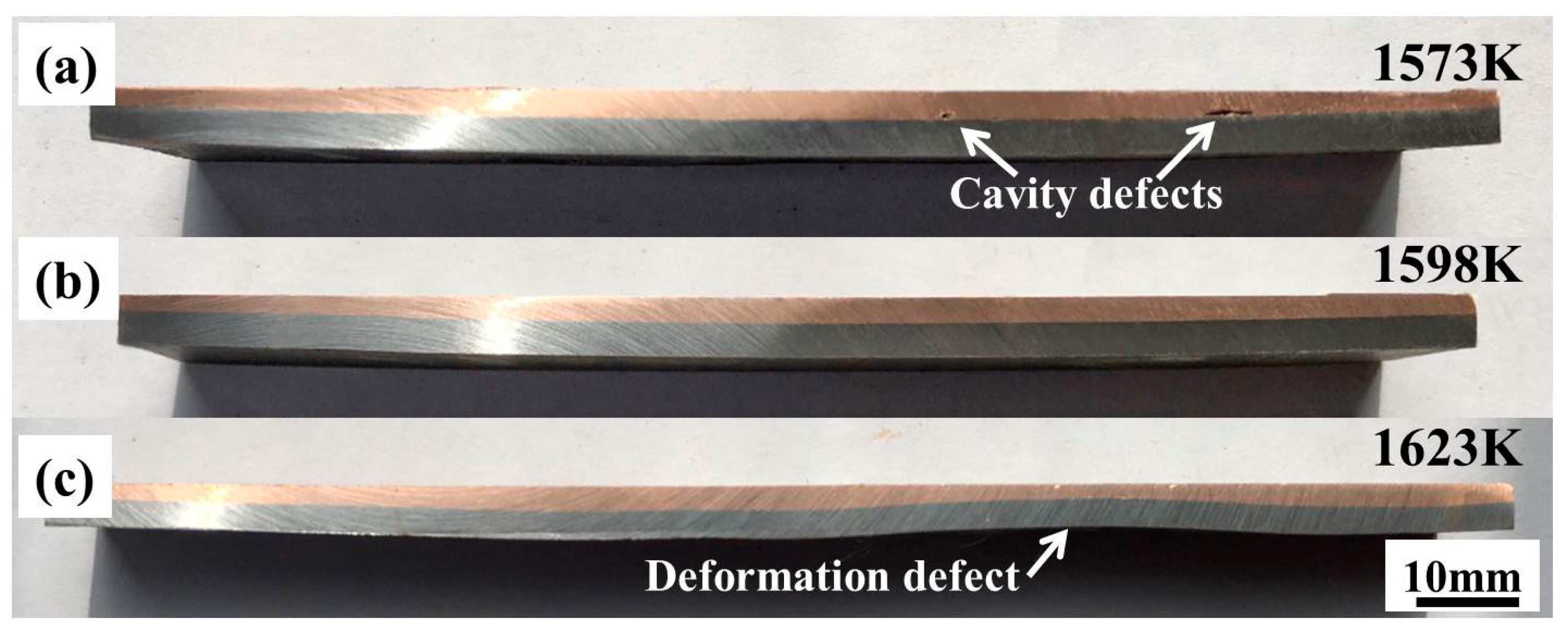
Figure 3 shows the longitudinal macrostructures of the Cu/Fe laminated composites obtained at different pouring temperature after surface milling. A straight interface was obtained at a pouring temperature of 1573 K (Figure 3a). At a lower pouring temperature, the Cu-Pb-Sn liquid was easily solidified, a good fluidity before passing though the rollers is difficult to maintain. Thus, some cavity defects appear near the interface as indicated by the arrows. When the pouring temperature increased to 1598 K, the Cu-Pb-Sn liquid was successfully combined onto the Q235 plate due to better fluidity and sufficient feeding through the rolling process. A good interface bond, as well as a flat surface was obtained under this condition (Figure 3b). It is noted that the laminated plate exhibited a slight warpage at both 1573 K and 1598 K, which can be attributed to the differential deformation between the Cu-Pb-Sn and Q235 layers during rolling. With further increase to 1623 K, a severe deformation was observed, as marked in Figure 3c. When the Cu-Pb-Sn liquid spread out on the Q235 plate, and passed through the rollers, heat transfer occurred between the Cu/Fe layers and between the composite and the rollers, respectively. Higher pouring temperature resulted in insufficient heat transfer at the Cu-Pb-Sn side, thus a large deformation took place in the Cu-Pb-Sn layer, leading to a warped-up deformation defect of the laminated composite.
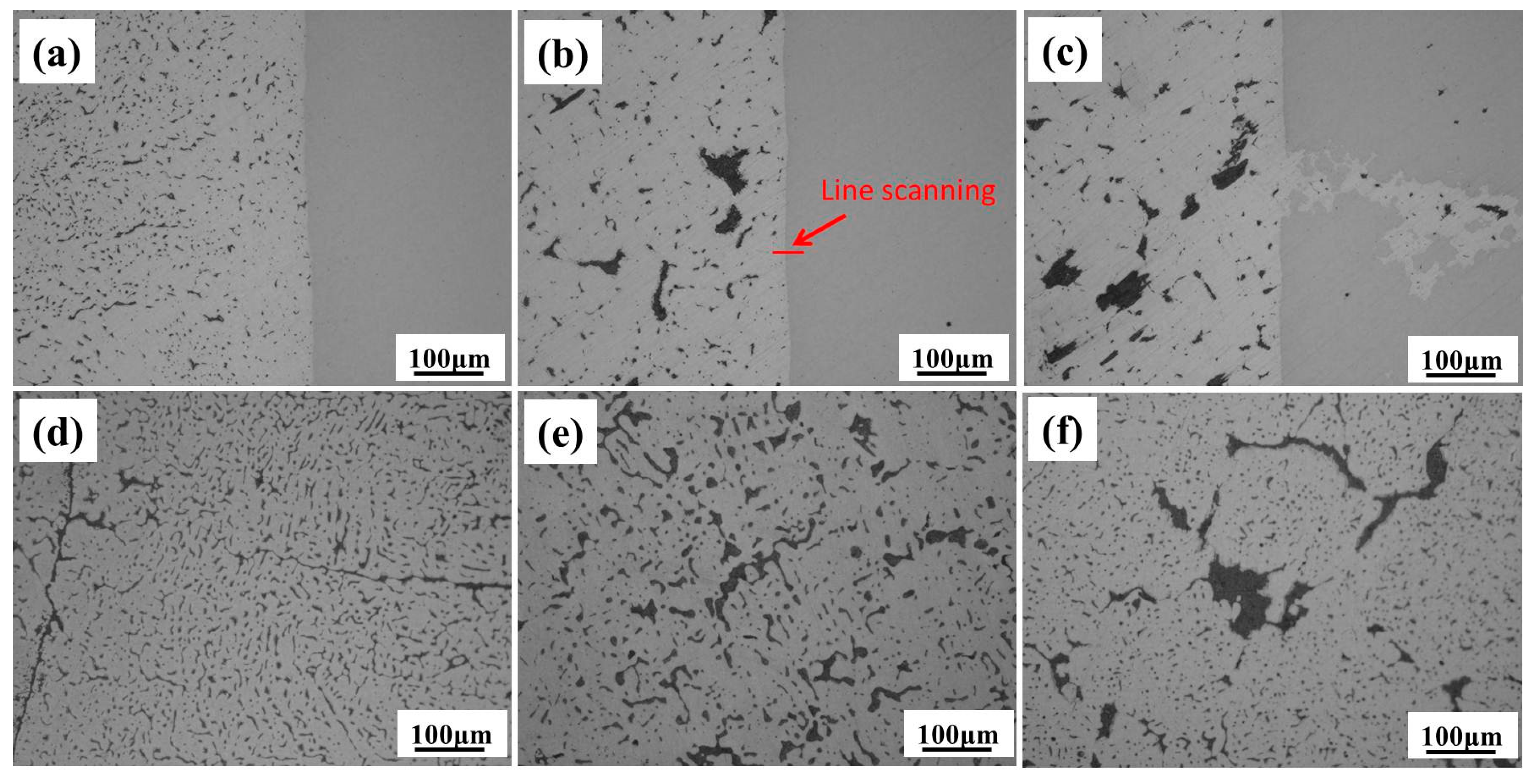
Figure 4 shows the microstructures of composite at the interface and within the Cu-Pb-Sn side. At a pouring temperature of 1573K (Figure 4a), the micro interface between the Cu-Pb-Sn alloy and Q235 was straight, with hardly any micro casting defects, such as cavities, cracks or excessive reaction. The fine precipitates of the Pb-rich phase on the Cu-Pb-Sn side were uniformly distributed. As the microstructure was presented without etching, no precipitates were found on the Q235 side. Inside the Cu-Pb-Sn layer (Figure 4d), the Pb-rich phases also presented in small particle shape. Owing to the cooling effect of rollers and the high thermal conductivity itself, the cladding Cu-Pb-Sn alloy was solidified rapidly, resulting in the insufficient growth of Pb-rich precipitates.
At pouring temperature 1598 K, the interfacial micro-morphology was still straight. The Pb-rich precipitates both near the interface (Figure 4b) and inside the Cu-Pb-Sn layer (Figure 4e) grew larger due to higher pouring temperature. With the pouring temperature further increased to 1623 K, some large cracks were found on the Q235 side (Figure 4c). The immediate cause is clearly the high temperature of Cu-Pb-Sn liquid, which triggered heat cracks at the surface of Q235 plate. A large deformation occurred during the rolling process, facilitating the growth of cracks. Then, the Cu-Pb-Sn liquid naturally diffused into the cracks under the rolling pressure. In addition, the size of Pb-rich phase increased with the increasing pouring temperature (Figure 4c,f).
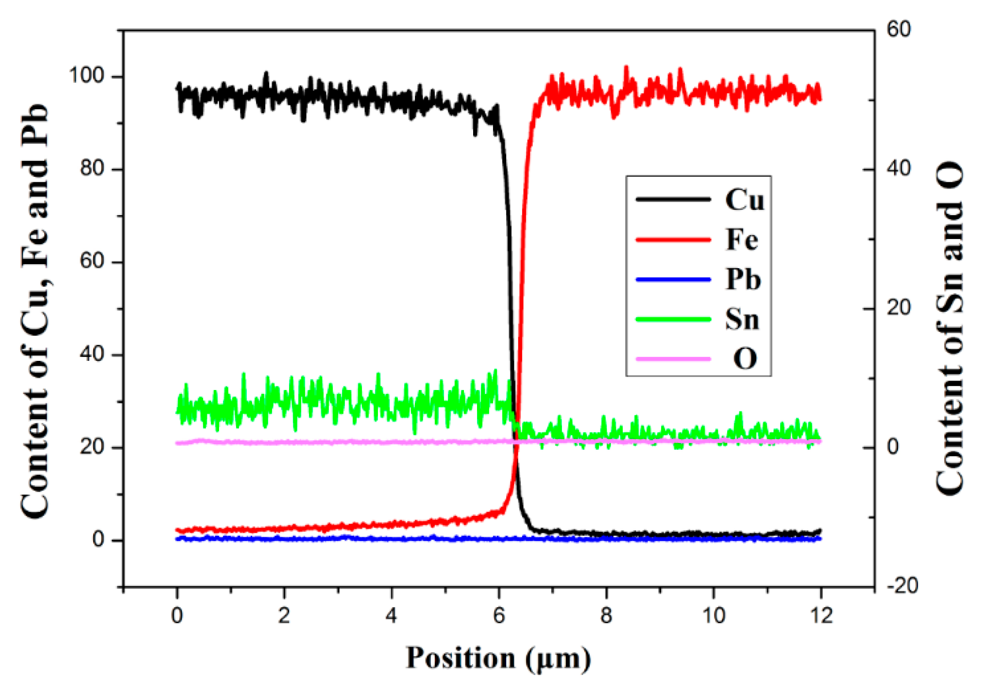
In order to study the element diffusion near the interface, line scanning analysis by EPMA was carried out at the position marked in Figure 4b. Figure 5 shows the content variations of the Cu, Fe, Pb, Sn, and O elements along this line. The contents of Pb and O elements were low on both sides. The undetectable O element revealed that the oxidation had not formed at the interface of Q235 plate during the fabrication process. As for the Pb, it formed Pb-rich precipitates in Cu based alloy and did not diffuse into the Q235 matrix.
Dramatic changes of Cu and Fe contents were found at the interface. The matrix on the Cu-Pb-Sn alloy side was Cu-Sn solid solution, the contents of which decreased to nearly zero at the boundary with Q235 side. The variation of Fe content displayed analogous behavior but from Q235 to Cu-Pb-Sn alloy side. It is worth noting that the content of Fe on the Cu side was not zero; a small amount of Fe diffused into the Cu matrix and was detected up to about 4 μm distance from the interface. In view of the contacting condition, Cu was in liquid and semisolid state, and was relatively active during the bonding process. Therefore, it was easier for Fe atoms to diffuse into the Cu matrix. Beyond that, the thin transition layer of other elements between Cu-Pb-Sn alloy and Q235 sides was less than 1 μm, without obviously gradual diffusion. On account of the low inter-solubility between Pb, Cu, and Fe, it is difficult to achieve a gradual diffusion layer or a micron-scale inter diffusion region. The result indicated that the laminated composite was metallurgically bonded mainly by the diffusion of Fe into the Cu matrix.
Further analysis demonstrated that the interfacial microstructures were not entirely uniform. Not all the interfaces appeared as shown in Figure 4. A few dark layers were also found between Cu-Pb-Sn and Q235, especially at the fringe areas of the composite plate, as shown in Figure 6. At a different pouring temperature, the average width of this layer was 38.3 μm (1573 K), 18.7 μm (1598 K), and 10.1 μm (1623 K), respectively. Its width decreased with increased temperature.
The line scanning analysis was conducted at their interfaces as marked by red lines in Figure 6a–c. The results in Figure 6d–f displayed that this layer was mainly formed by Pb-rich phase, connecting both Cu-Pb-Sn and Q235 layers. On the Cu-Pb-Sn side, a transition layer with average thickness 7 μm can be observed between Cu-Pb-Sn and Pb-rich layers. Since the primary Cu and Pb-rich phase were continuously divided from the Cu-Pb-Sn liquid during the cladding process, and solidified rapidly when passing through the rollers. The Cu- and Pb-rich phases could not separate completely under this condition, thus an inter-diffusion layer formed between Cu-Pb-Sn alloy and Pb-rich layer. A similar transition layer could be found on the Q235 side between Q235 and Pb-rich layers, which was gradual and wide, indicating the existent of the inter-diffusion between Pb and Fe. Hence, the Pb-rich layer is a compatible transition region between the Cu-Pb-Sn and Q235 layers.
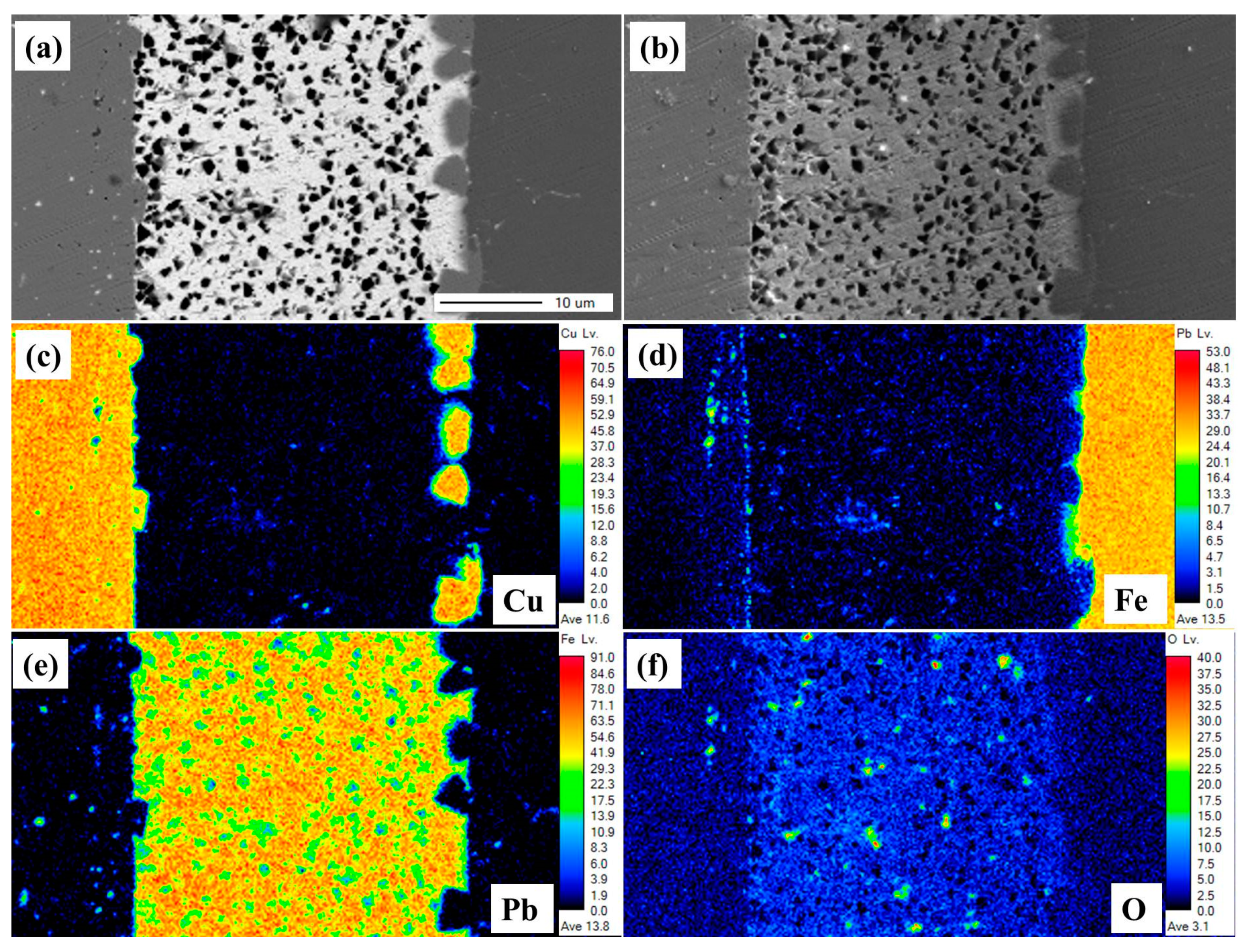
The mapping analysis was carried out for this Pb-rich layer (1573 K) as marked in Figure 6a. It is seen from the backscattered electron image (BEI, Figure 7a) and secondary electron image (SEI, Figure 7b) that the interfaces between the Cu-Pb-Sn alloy, Pb-rich, and Q235 layers were not regular. A large amount of cavities were found within the Pb-rich layer, which were probably caused by the abrasive and oxide particles during the grinding and polishing process, as Pb is very soft. Figure 7c–f showed the distribution of elements Cu, Fe, Pb, and O. There was a clear distinction among different layers, as well as a slight gradual diffusion layer near the interface. In Figure 7d, a gradual change of the Fe element was seen between the Pb-rich and Q235 layers, indicating an inter-diffusion region between Pb and Fe, which corresponds with the line scanning in Figure 6. Some Fe was even detected at the boundary of the Cu side that agrees with the diffusion of Fe into the Cu matrix (Figure 5).
It is interesting that some Cu rich regions were found between the Pb-rich and Q235 layers, which could be attributed to the solidification path of Cu-Pb-Sn alloys. Based on the equilibrium phase diagram of Cu-Pb binary alloy, the solidification path of Cu-12Pb-2Sn is as follow: primary Cu starts to crystallize when the temperature is below 1323 K by the isomorphous reaction L→α(Cu) + L2. With the temperature drop to 1228 K, monotectic reaction L1→α(Cu) + L2 occurs. Then the eutectic reaction takes place at 872 K to form eutectic Cu and Pb through L2→Cu + Pb. For the fabrication process in this study, when the Cu-Pb-Sn alloy liquid poured onto the Q235 plate, the temperature of the liquid soon decreased due to the high thermal conductivity of the Cu-Pb-Sn alloy and the huge temperature difference between the liquid (1573 K) and preheated plate (573 K). With the contacting temperature dropped below 1323 K, the liquid at the interface started to solidify, leading to the formation of a primary Cu phase near the Q235 side. While the Pb-rich liquid was divided from Cu-Pb-Sn alloy, it easily entered into the gap between the Cu-Pb-Sn liquid and Q235 plate, forming the Pb-rich layer. When the composite plate went through the rollers, the liquid solidified rapidly under the cold rollers. Thus, with decreasing pouring temperature, the Pb-rich liquid L1 and L2 were easier to squeeze out, and the width of Pb-rich layer increased.
The distribution of O element in Figure 7f demonstrates the presence of some oxides on the cross section within the Pb layer rather than at the interface between different layers. It may be oxide particles from the liquid polishing agent, caught in the cavities on the surface of the Pb-rich layer. Results also revealed that no oxidation on the surface of the Q235 formed during the preparation process, as no oxide layer was found near the interface.
3.2. Interfacial Property
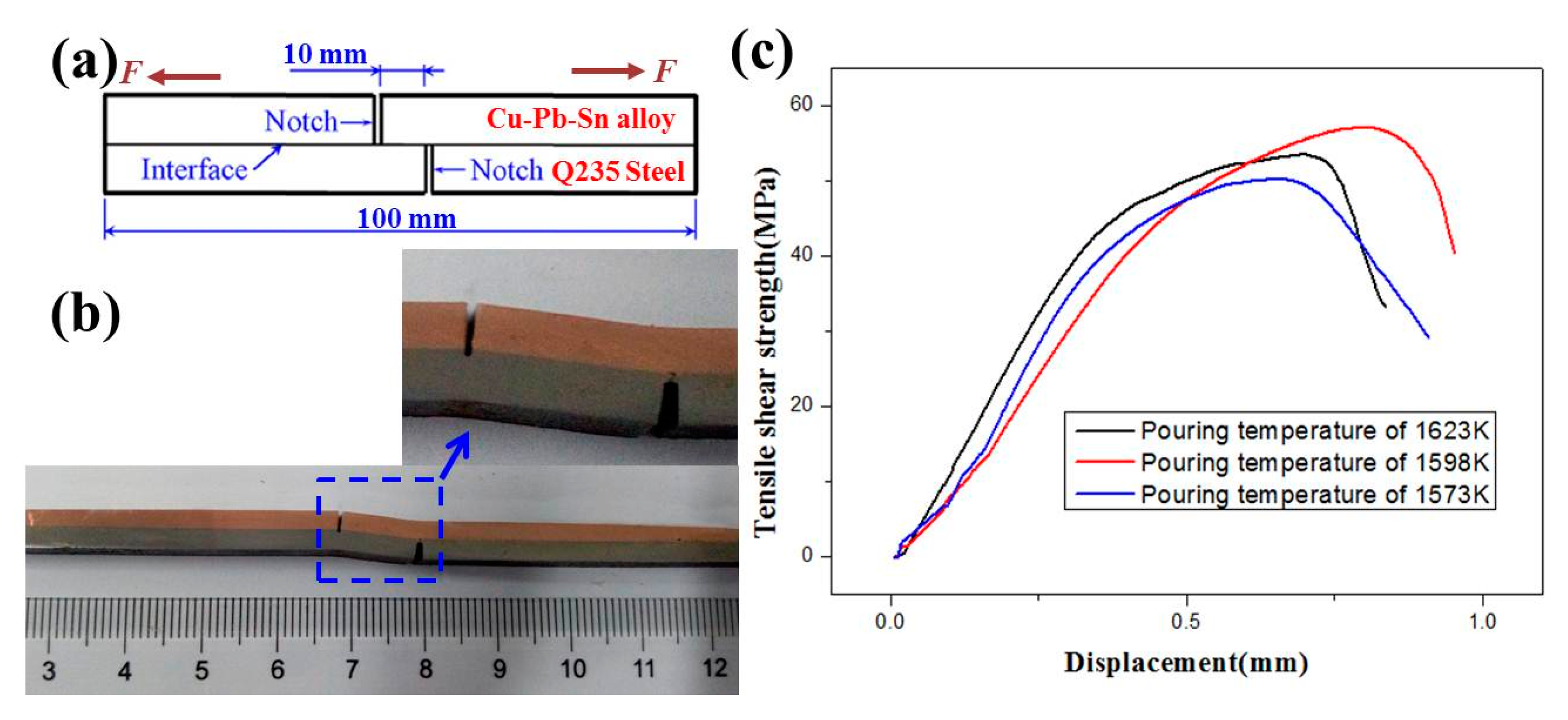
The tensile test is an efficient approach to examine the interface strength. Three samples for each experimental condition were selected to evaluate the strength of the interface bonding. Figure 8a presents the schematic drawing of the tensile-shear specimen. The specimens were cut from the longitude section of the composite plate, and the tensile direction was parallel to the rolling direction. The shear strength τ can be calculated by the following equation:
where F is the applied force, and A is the impact area (10 × 10 mm2 in this study). The failed sample after the test is shown in Figure 8b. The results indicate that all the laminated composite specimens failed at the Cu-Pb-Sn alloy side, while the interface remained in a good condition. It can be considered that the tensile-shear strength of the interface is higher than that of the cladding Cu-Pb-Sn alloy, the failure occurred when the ultimate tensile strength of the Cu-Pb-Sn alloy was reached during the tensile test. On one hand, near the interface during the tensile-shear strength test, the crack first took place at the Pb-rich precipitates/layers due to its low strength, and then tended to grow and spread into the softer Cu-Pb-Sn side. On the other hand, due to the eutectic reaction and inter diffusion, the bond strengthening between the layers was higher than the strength of Cu-Pb-Sn alloy. Thus, all the specimens failed in the Cu-Pb-Sn alloy side.
Figure 8c showed the shear strength-displacement curves of a random sample taken under each experimental condition. The results revealed that the average tensile-shear strengths at pouring temperatures of 1573 K, 1598 K, and 1623 K were 52.29 MPa, 57.68 MPa, and 54.83 MPa, respectively. Due to the similar microstructures at most interfacial region under different conditions, the strength values are nearly uniform. The minor difference should come from the different interfacial quality. The casting defects near the interface at pouring temperature 1573 K (cavities, as shown in Figure 3a) and 1623 K (cracks, as shown in Figure 4c) may cause the degradation of tensile shear strength. Thus, the Cu-Pb-Sn/Q235 laminated composite obtained at 1598 K shows the highest tensile-shear strength.
3.3. Finite-Element Simulation
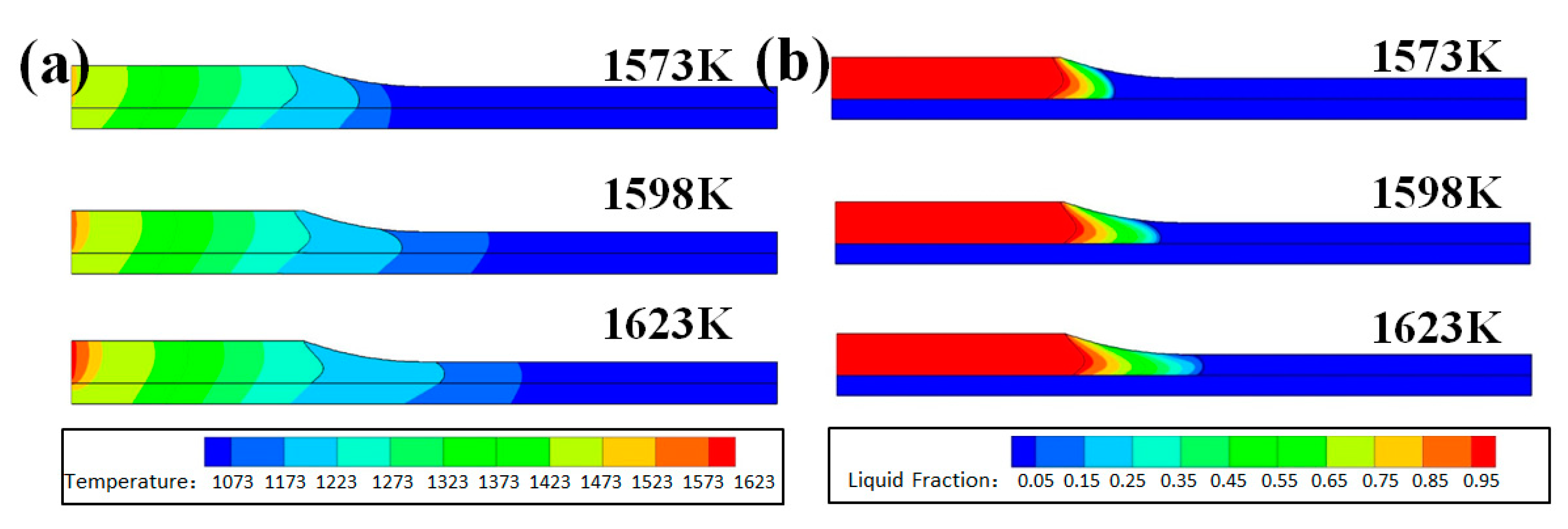
In order to investigate the relationship between the pouring temperature of Cu-Pb-Sn alloy and the combination, a comprehensive mathematical model was developed to describe the solidification process. Figure 9 shows the calculation result of the temperature field and solid fraction profiles during the rolling fabricating process. It is clear from the results that the pouring temperature of the Cu-Pb-Sn alloy has a profound influence on the distribution of temperature.
When the Cu-Pb-Sn alloy was poured at 1573 K, the temperature of Cu-Pb-Sn alloy soon decreased after spreading out on the Q235 plate (preheated at 773 K), it further reduced below approximate 1223 K before the composite got into the rollers. At this time, the primary Cu in the liquid had already crystallized by the isomorphous reaction at 1323 K and the monotectic reaction at 1228 K. The Pb-rich liquid, another resultant of these two reactions, was squeezed out by the growth of primary Cu dendrites. Then they were fast solidified when the composite plate got through the rollers. During the eutectic reaction at 872 K, the Cu and Pb grew separately and finally completely solidified, forming fine Pb-rich precipitates in the matrix.
However, due to the temperature nonuniformity at the fringe areas, the Pb-rich liquid could enter into the gap between the solid Cu and Q235 plate before through the rolling. It was solidified there to form the Pb-rich layer between Cu-Pb-Sn alloy and Q235 during the rolling process. The liquid with lower temperature always contains higher content of Pb, thus the Cu-Pb-Sn/Q235 laminated composite at pouring temperature of 1523 K possessed a thicker Pb-rich layer of 38.3 μm, and the thickness decreased gradually by increasing the pouring temperature.
At 1598 K, the contacting temperature between Cu-Pb-Sn alloy and Q235 increased, the covering Cu-Pb-Sn alloy remained in a semi-solid state at the beginning of rolling. This temperature provided an appropriate condition of the semi-solid region, to effectively keep liquidity and avoid casting defects.
When the pouring temperature was 1598 K, the temperature after passing through the rollers was about 1223 K, indicating that the Cu-Pb-Sn alloy was not solidified completely. At that moment, the monotectic reaction was in progress to form Cu and L2. The Pb-rich liquid continually separated from the Cu matrix and outflowed from the interdendritic region to the surface of Cu-Pb-Sn alloy, until the eutectic reaction L2→Cu + Pb was completely done at 872 K. It resulted in Pb macro segregation; the composition of Pb on the surface was higher than that inside the Cu-Pb-Sn alloy layer. In this case, it should avoid an exorbitant pouring temperature.
Figure 9b shows the influence of the pouring temperature on the distribution of the solid fraction during the rolling fabricating process. The semi-solid region expanded while the pouring temperature increased. In the case of 1573 K, the temperature fell rapidly after contacting with the rollers, the semi-solid region was mainly near the entrance of the rollers. The Cu-Pb-Sn alloy had already solidified during the deformation process, thus the inadequate feeding was caused by the cavity defects at the interface, as shown in Figure 2a. With the pouring temperature increasing to 1598 K and 1623 K, a wider mushy region in the center of Cu-Pb-Sn alloy could be observed. The extension of a semisolid state region is of great importance to the bonding between the Cu-Pb-Sn alloy and Q235. Due to the good fluidity of semi-solid state, casting defects hardly formed at the interface under these conditions.
4. Conclusions
In the present work, a horizontal semisolid rolling procedure was used to fabricate the Cu-12Pb-2Sn/Q235 steel laminated composite, and was evaluated as a potential method. The results are listed below.
- A good bonding between Cu-Pb-Sn alloy and Q235 steel was achieved at the pouring temperature of 1598 K, without casting defects at the interface or excessive deformation of the laminated composite.
- The Cu-Pb-Sn alloy and Q235 steel were bonded mainly by the diffusion of Fe into Cu matrix as well as a handful of micron-scale Pb-rich layers, the width of which decreased by increasing the pouring temperature.
- The average tensile-shear strength 57.68 MPa was obtained at a pouring temperature of 1598 K, which can fulfill the requirements for further extrusion process.
- Finite-element simulation was conducted to analyze the temperature field and solidification process during the semisolid rolling. A wide semi-solid region was observed at 1598 K in the simulation, which provided good fluidity and suppressed the formation of casting defects.
Author Contributions
Conceptualization, T.L. and T.W.; Methodology, Y.Z. and J.L.; Software, J.L.; Formal Analysis, Y.Z. and Y.F.; Investigation, J.J.; Resources, T.L.; Data Curation, Y.L. and Q.G.; Writing—Original Draft Preparation, Y.Z.; Writing—Review & Editing, Y.F.; Project Administration, T.L.; Funding Acquisition, T.L., Y.Z. and Y.F.
Funding
The authors gratefully acknowledge the support of the National Natural Science Foundation of China (Nos. 51501027 and 51704029), the Open Research Fund from State Key Laboratory of Metal Material for Marine Equipment and Application (No. SKLMEA-K201701), and the Fundamental Research Funds for the Central Universities of China DUT17RC (4).
Conflicts of Interest
The authors declare no conflict of interest.
References
- Liu, N.; Jie, J.; Lu, Y.; Wu, L.; Fu, Y.; Li, T. Characteristics of clad aluminum hollow billet prepared by horizontal continuous casting. J. Mater. Process. Technol. 2014, 214, 60–66. [Google Scholar] [CrossRef]
- Sun, J.; Song, X.; Wang, T.; Yu, Y.; Sun, M.; Cao, Z.; Li, T. The microstructure and property of Al–Si alloy and Al–Mn alloy bimetal prepared by continuous casting. Mater. Lett. 2012, 67, 21–23. [Google Scholar] [CrossRef]
- Fu, Y.; Jie, J.; Wu, L.; Park, J.; Sun, J.; Kim, J.; Li, T. Microstructure and mechanical properties of Al–1Mn and Al–10Si alloy circular clad ingot prepared by direct chill casting. Mater. Sci. Eng. A 2013, 561, 239–244. [Google Scholar] [CrossRef]
- Zhang, Y.; Fu, Y.; Jie, J.; Wu, L.; Svynarenko, K.; Guo, Q.; Li, T.; Wang, T. Characteristics of copper-clad aluminum rods prepared by horizontal continuous casting. Met. Mater. Int. 2017, 23, 1197–1203. [Google Scholar] [CrossRef]
- Azimi, M.; Toroghinejad, M.R.; Shamanian, M.; Kestens, L. The Effect of strain on the formation of an intermetallic layer in an Al-Ni laminated composite. Metals 2017, 7, 445. [Google Scholar] [CrossRef]
- Kümmel, F.; Kreuz, M.; Hausöl, T.; Höppel, H.W.; Göken, M. Microstructure and mechanical properties of accumulative roll-bonded AA1050A/AA5005 laminated metal composites. Metals 2016, 6, 56. [Google Scholar] [CrossRef]
- Yuan, X.; Tang, K.; Deng, Y.; Luo, J.; Sheng, G. Impulse pressuring diffusion bonding of a copper alloy to a stainless steel with/without a pure nickel interlayer. Mater. Des. 2013, 52, 359–366. [Google Scholar] [CrossRef]
- Yang, Y.; Wang, D.; Lin, J.; Khan, D.F.; Lin, G.; Ma, J. Evolution of structure and fabrication of Cu/Fe multilayered composites by a repeated diffusion-rolling procedure. Mater. Des. 2015, 85, 635–639. [Google Scholar] [CrossRef]
- Pan, D.; Gao, K.; Yu, J. Cold roll bonding of bimetallic sheets and strips. Mater. Sci. Technol. 1989, 5, 934–949. [Google Scholar] [CrossRef]
- Ren, D.; Liu, L. Interface microstructure and mechanical properties of arc spot welding Mg-steel dissimilar joint with Cu interlayer. Mater. Des. 2014, 59, 369–376. [Google Scholar] [CrossRef]
- Qu, Y.D.; Zhang, W.J.; Kong, X.Q.; Zhao, X. Theoretical investigation of calculating temperatures in the combining zone of Cu/Fe composite plate jointed by explosive welding. Phys. Met. Metall. 2016, 117, 260–266. [Google Scholar] [CrossRef]
- Rodriguez, J.A.; Goodman, D.W. The nature of the metal-metal bond in bimetallic surfaces. Science 1992, 257, 897–903. [Google Scholar] [CrossRef] [PubMed]
- Nakagawa, Y. Liquid immiscibility in copper-iron and copper-cobalt systems in the supercooled state. Acta Metall. 1958, 6, 704–711. [Google Scholar] [CrossRef]
- Chuang, Y.Y.; Schmid, R.; Chang, Y.A. Thermodynamic analysis of the iron-copper system I: The stable and metastable phase equilibria. Metall. Trans. A 1984, 15, 1921–1930. [Google Scholar] [CrossRef]
- He, J.; Zhao, J.Z.; Wang, X.F.; Gao, L.L. Microstructure development in finely atomized droplets of copper-iron alloys. Metall. Mater. Trans. A 2005, 36, 2449–2454. [Google Scholar] [CrossRef]
- Yasuda, H.; Ohnaka, I.; Kawakami, O.; Ueno, K.; Kishio, K. Effect of magnetic field on solidification in Cu-Pb monotectic alloys. ISIJ Int. 2007, 43, 942–949. [Google Scholar] [CrossRef]
- Palafox-Hernandez, J.P.; Laird, B.B.; Asta, M. Atomistic characterization of the Cu–Pb solid–liquid interface. Acta Mater. 2011, 59, 3137–3144. [Google Scholar] [CrossRef]
- Buchanan, V.E.; Molian, P.A.; Sudarshan, T.S.; Akers, A. Frictional behavior of non-equilibrium Cu-Pb alloys. Wear 1991, 146, 241–256. [Google Scholar] [CrossRef]
- Molian, P.A.; Buchanan, V.E.; Sudarshan, T.S.; Akers, A. Sliding wear characteristics of non-equilibrium Cu-Pb alloys. Wear 1991, 146, 257–267. [Google Scholar] [CrossRef]
- Zhang, J.; Liu, S.; Lu, Y.; Jiang, L.; Zhang, Y.; Li, T. Semisolid-rolling and annealing process of woven carbon fibers reinforced Al-matrix composites. J. Mater. Sci. Technol. 2017, 33, 623–629. [Google Scholar] [CrossRef]
- Zhang, J.; Liu, S.; Lu, Y.; Yin, X.; Zhang, Y.; Li, T. Liquid rolling of woven carbon fibers reinforced Al5083-matrix composites. Mater. Des. 2016, 95, 89–96. [Google Scholar] [CrossRef]
Figure 1.
Schematic diagram of experimental procedures, (a) grinding and polishing, (b) preheating, (c) semisolid rolling, (d) achieved composite.
Figure 1.
Schematic diagram of experimental procedures, (a) grinding and polishing, (b) preheating, (c) semisolid rolling, (d) achieved composite.

Figure 2.
Schematic diagrams of (a) rolling fabricating process and (b) finite-element model.
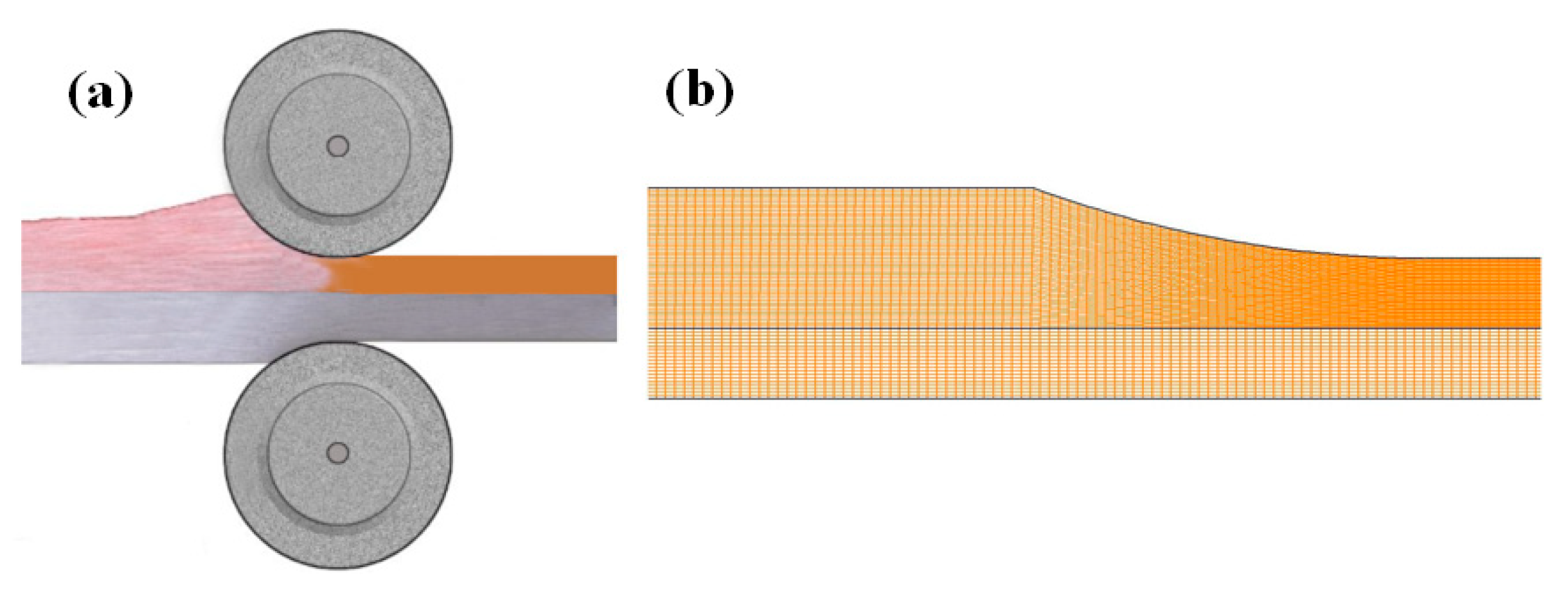
Figure 3.
Macrostructures of Cu-Pb-Sn/Q235 laminated composite at different pouring temperature (a) 1573 K, (b) 1598 K and (c) 1623 K.
Figure 3.
Macrostructures of Cu-Pb-Sn/Q235 laminated composite at different pouring temperature (a) 1573 K, (b) 1598 K and (c) 1623 K.

Figure 4.
Interfacial microstructures of Cu-Pb-Sn/Q235 laminated composite (a–c) and internal microstructures of Cu-Pb-Sn alloy (d–f) at different pouring temperature of (a,d) 1573 K, (b,e) 1598 K, and (c,f) 1623 K.
Figure 4.
Interfacial microstructures of Cu-Pb-Sn/Q235 laminated composite (a–c) and internal microstructures of Cu-Pb-Sn alloy (d–f) at different pouring temperature of (a,d) 1573 K, (b,e) 1598 K, and (c,f) 1623 K.

Figure 5.
The line scanning result at the position as marked in Figure 4b.
Figure 5.
The line scanning result at the position as marked in Figure 4b.

Figure 6.
The Interfacial microstructures of the lead layer between the Cu-Pb-Sn and Q235 layers, and the line scanning results at different pouring temperatures (a,d) 1573 K, (b,e) 1598 K, and (c,f) 1623 K.
Figure 6.
The Interfacial microstructures of the lead layer between the Cu-Pb-Sn and Q235 layers, and the line scanning results at different pouring temperatures (a,d) 1573 K, (b,e) 1598 K, and (c,f) 1623 K.
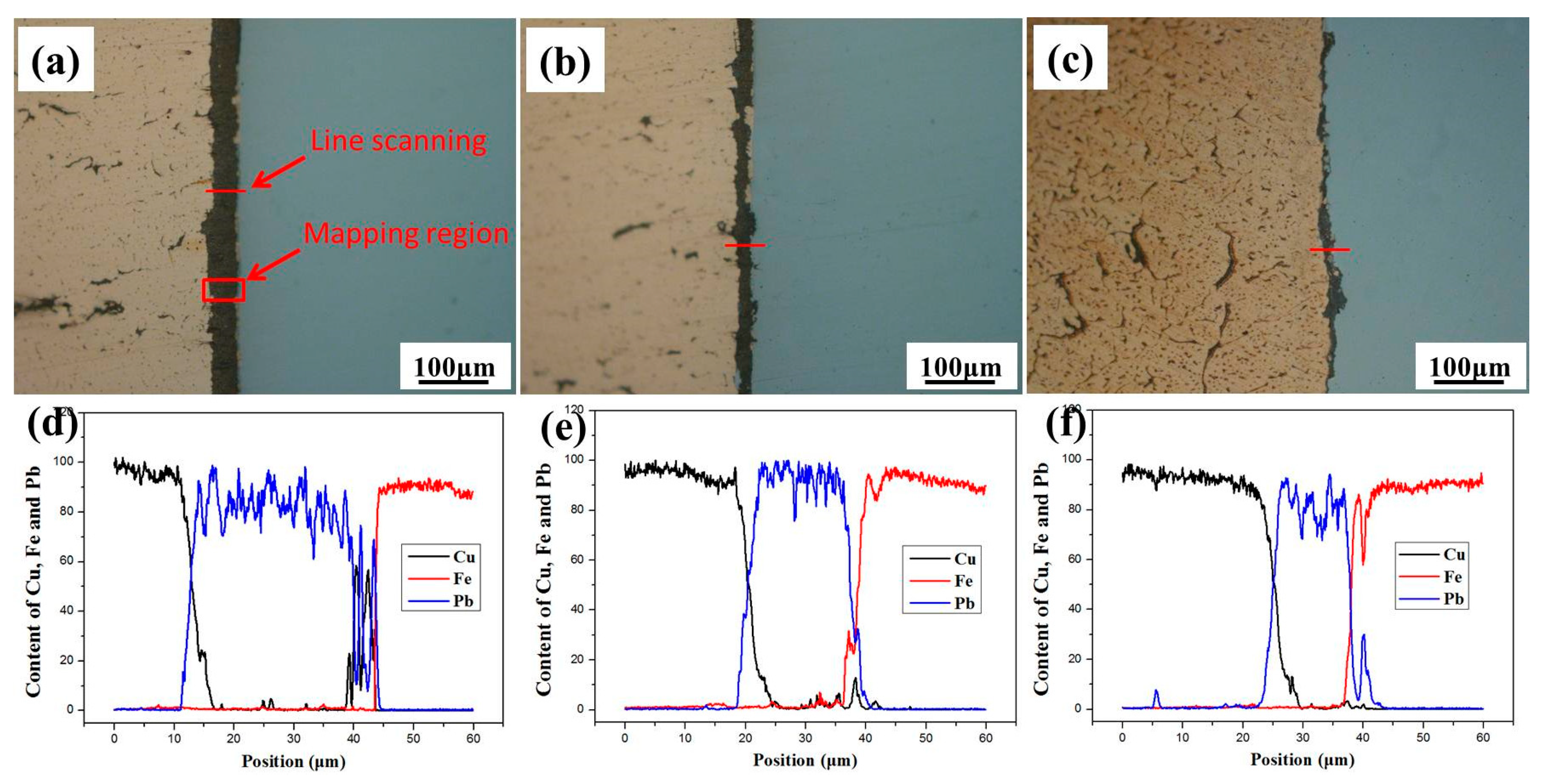
Figure 7.
The mapping analysis of multi-layer interface, (a) backscattered electron image, (b) secondary electron image, and the distribution of element (c) Cu, (d) Fe, (e) Pb and (f) O.
Figure 7.
The mapping analysis of multi-layer interface, (a) backscattered electron image, (b) secondary electron image, and the distribution of element (c) Cu, (d) Fe, (e) Pb and (f) O.

Figure 8.
(a) Schematic illustration of the tensile shear specimen, (b) the failed tensile shear sample, and (c) shear strength.
Figure 8.
(a) Schematic illustration of the tensile shear specimen, (b) the failed tensile shear sample, and (c) shear strength.

Figure 9.
Effect of the pouring temperature on the (a) temperature field and (b) solid fraction profiles during the rolling fabricating process.
Figure 9.
Effect of the pouring temperature on the (a) temperature field and (b) solid fraction profiles during the rolling fabricating process.

Table 1.
Chemical compositions of Cu-Pb-Sn alloy and Q235 plate (wt.%).
| Material | Cu | Pb | Sn | Fe | S | C | Mn | Cr | Si |
|---|---|---|---|---|---|---|---|---|---|
| Cu-Pb-Sn alloy | Bal. | 11.95 | 2.07 | <0.01 | <0.01 | - | - | - | - |
| Q235 steel | <0.25 | - | - | Bal. | <0.04 | 0.21 | < 1.2 | 0.2 | <0.35 |
© 2018 by the authors. Licensee MDPI, Basel, Switzerland. This article is an open access article distributed under the terms and conditions of the Creative Commons Attribution (CC BY) license (http://creativecommons.org/licenses/by/4.0/).
Share and Cite
MDPI and ACS Style
Zhang, Y.; Liu, J.; Fu, Y.; Jie, J.; Lu, Y.; Guo, Q.; Wang, T.; Li, T. Microstructure and Fabrication of Cu-Pb-Sn/Q235 Laminated Composite by Semi-Solid Rolling. Metals 2018, 8, 722. https://doi.org/10.3390/met8090722
AMA Style
Zhang Y, Liu J, Fu Y, Jie J, Lu Y, Guo Q, Wang T, Li T. Microstructure and Fabrication of Cu-Pb-Sn/Q235 Laminated Composite by Semi-Solid Rolling. Metals. 2018; 8(9):722. https://doi.org/10.3390/met8090722
Chicago/Turabian StyleZhang, Yubo, Jiaming Liu, Ying Fu, Jinchuan Jie, Yiping Lu, Qingtao Guo, Tongmin Wang, and Tingju Li. 2018. "Microstructure and Fabrication of Cu-Pb-Sn/Q235 Laminated Composite by Semi-Solid Rolling" Metals 8, no. 9: 722. https://doi.org/10.3390/met8090722
Note that from the first issue of 2016, this journal uses article numbers instead of page numbers. See further details here.