Degradation Behavior of Micro-Arc Oxidized ZK60 Magnesium Alloy in a Simulated Body Fluid

1
School of Materials Science and Engineering, Jiangsu University of Science and Technology, Zhenjiang 212003, China
2
School of Science, Jiangsu University of Science and Technology, Zhenjiang 212003, China
*
Author to whom correspondence should be addressed.
Metals 2018, 8(9), 724; https://doi.org/10.3390/met8090724
Submission received: 15 August 2018
/
Revised: 11 September 2018
/
Accepted: 12 September 2018
/
Published: 14 September 2018
Abstract
:Bio-ceramic coatings were synthesized on ZK60 magnesium alloys by micro-arc oxidation (MAO). The degradation behavior of the ZK60 alloys with and without MAO coating in the simulated body fluid (SBF) was studied. The samples were characterized by means of scanning electron microscopy (SEM), laser scanning confocal microscopy (CLSM), and X-ray diffraction (XRD). Electrochemical impedance spectroscopy (EIS) was used to study the degradation behavior. The results showed that the porous MAO coating mainly consisted of MgO, Mg2SiO4, Mg3(PO4)2, and CaCO3. The pH values of both coated and uncoated samples increased over time. However, the pH values of the SBF for coated samples always maintained a lower level compared with those for the uncoated samples. Thereby, the coated samples showed a much lower degradation rate. After immersion in SBF for 5 days, corrosion product containing Ca and P was found on both samples, while the deposition was more active on the coated samples. The degradation models for the uncoated and coated samples in the SBF are also proposed and discussed.

1. Introduction
Magnesium (Mg) is an essential element for the human body, and takes part in more than 300 biochemical reactions in the body [1,2,3,4]. Compared with other implants, the density and elastic modulus of Mg alloys are much closer to human bones, and thus stress shielding can be avoided [5,6,7,8,9]. Mg alloys have a good biocompatibility and no cytotoxicity [10,11,12], and can degrade in vivo which obviates the need for a second surgery [13,14]. Furthermore, they can induce the formation of bone [15], and thus the damaged bone can be healed more quickly [16,17,18,19]. Therefore, Mg and its alloys have gained extensive attention as biomedical materials. However, the degradation rate of Mg alloys is much faster than the healing rate of the damaged bone [20,21]. Just like the other biomedical materials, a further treatment is always needed [22,23].
In general, the degradation rate of alloys can be controlled mainly by tailoring their compositions or by conducting surface treatments [24,25]. Surface treatment can effectively improve the corrosion resistance of alloys, and conversion coating, anodizing, micro-arc oxidation (MAO), and other technologies are representatives of this treatment [26,27,28,29,30]. Hakimizad et al. [31] reported that micro-arc oxidation coatings are formed by numerous short-lived micro-arc discharges on the entire surface occurring at voltages higher than the breakdown voltages of the oxide coating, the hard, thick, and adherent oxide coatings on light metals (e.g., Al and Mg) and on their alloys can be obtained by micro-arc oxidation technology. Benjamin et al. [32] found that the corrosion resistance of AZ31 Mg alloys in simulated body fluid (SBF) was significantly improved after MAO treatment. Sankara Narayanan et al. [33] reported that MAO treatment could improve the hardness and bonding strength of Mg substrate. Therefore, micro-arc oxidation is a convenient technique to obtain porous and corrosion-resistant bio-ceramic coatings.
A thorough understanding of the corrosion behavior of Mg alloys in the physiological environment is a basic requirement in order to control their degradation rates [34]. A number of researchers have investigated the corrosion behavior of Mg alloys. Gu et al. [19] studied the corrosion product layer formed on the AZ31 alloy surface during immersion in SBF, and found that it enhanced the alloy’s corrosion resistance. A corrosion model proposed by Gu et al. [35] indicated that the corrosion resistance of a coating depends on the thickness of the compact layer and the compactness of the MAO coating. Lin et al. [36] demonstrated that the degradation of the MAO coating was accompanied by the formation of a degradation layer and a Ca-P deposition layer, which would improve the biocompatibility of the coating surface.
To our knowledge, most studies focus on the corrosion behavior of MAO coatings on AZ91 or AZ31 Mg alloys (whose chemical composition contain Al, well-known as a main inducing element to Alzheimer’s disease) in SBF [37,38]. Some researchers have chosen to develop their own self-designed Mg alloys with bio-safe alloying elements [39,40,41], taking a great deal of R&D time and cost. ZK60 (Mg-Zn-Zr) Mg alloy is not only commercially available, but its alloying element Zn is a trace element essential to the human body, and Zr (another alloying element)-based materials (e.g., ZrO, Zr-Cu-Al-Ag alloy, Zr-2.5Nb, Zr-1.5Nb-1Ta crystalline alloys, etc.) exhibit satisfactory biocompatibility [42,43,44]. Therefore, considering both safety and economy, it is essential to understand the degradation behavior of micro-arc-oxidized ZK60 Mg alloy in SBF.
In this work, MAO was conducted on ZK60 Mg alloy to prepare bio-ceramic coatings in an optimized electrolyte system. Both coated and uncoated samples were immersed in SBF for 30 days. SEM and laser scanning confocal microscopy (CLSM), were used to observe the morphologies of the samples. XRD and Fourier transform infrared spectroscopy (FTIR) were employed to investigate the compositions of coatings and corrosion products. The corrosion behavior was studied by electrochemical test paired with a static weight-loss method. Finally, in vitro SBF soaking was conducted to analyze the degradation behavior of the samples with and without MAO coating.
2. Materials and Methods
2.1. Coating Preparation
Commercially available rolled ZK60 Mg alloy (Mg-5.8 wt % Zn-0.45 wt % Zr) was used as the substrate in this work. The samples were cut into 5 mm × 20 mm × 20 mm plates by means of an electric arc CNC wire-cut machine (Haima Numerical Control Equipment Co., Ltd., Suzhou, China) and then ground up to 1200 grits using SiC paper (Wuhan advanced technology Co., Ltd. Wuhan, China), ultrasonically cleaned, rinsed with distilled water, and dried in the air.
MAO was conducted on ZK60 samples under constant-current mode in a self-developed compound electrolyte with a composition of 6 g/L Na2SiO3·9H2O, 0.5 g/L Ca(CH3COO)2·H2O, 0.8 g/L (NaPO3)6, 0.5 g/L NaH2PO4·H2O, and 2.8 g/L NaOH. Current density, frequency, positive duty ratio, negative duty ratio, and reaction time were respectively set as 20 A/dm2, 500 Hz, 40%, 60%, and 15 min.
2.2. Immersion Test
The coated and uncoated samples were immersed in an SBF with ion concentrations almost equal to human blood plasma (Table 1) for 30 days. Three samples were tested to evaluate one time spot of corrosion time. The reagents and dose for preparing 1000 mL SBF are shown in Table 2. The reagents were dissolved one-by-one in distilled water at 36.5 ± 0.5 °C in the order shown in Table 2. The pH value was adjusted to 7.45 with Tris and HCl solution at 36.5 ± 0.5 °C.
Each sample was soaked in a plastic beaker containing 120 mL of SBF in a thermostat water bath at 36.5 ± 0.5 °C. The ratio of the sample’s surface area (cm2) to SBF volume (mL) was 1:10 [45,46,47]. The pH values of the SBFs of three parallel tests were recorded to obtain an average value every 24 h, and the SBFs were refreshed after recording. A couple of coated and uncoated samples were removed from the SBF for further examination every 5 days. The corrosion rate of the coating was characterized by weight loss ratio. In the equation below, Rwt is the weight loss ratio, M is the quality of the sample before corrosion, and M1 is the quality of the sample after corrosion:
Rwt = (M−M1)/M × 100%
2.3. Characterization
Scanning electron microscopy (SEM, JSM-6480, JEOL, Tokyo, Japan) was used to observe the surface morphology and cross section morphology of the coatings. A laser scanning confocal microscope (CLSM, OLS4000, Olympus, Tokyo, Japan) was used to measure the roughness of the coated samples by taking the average value of five points. X-ray diffraction (XRD, OxfordCMI233, 40 kW, SHIMADZU, Tokyo, Japan) analysis was carried out with monochromatic Cu Kα radiation over a 2θ range of 20° to 90° with a scanning rate of 4°/min. Electrochemical impedance spectroscopy (EIS, EG&G M283, AUTOLAB, Bern, Switzerland) was used to study the degradation behavior of samples. The EIS tests were conducted in SBF at 36.5 ± 0.5 °C, at the open circuit potential (OCP), with a 10 mV alternating signal from 100 kHz to 100 mHz. The equivalent circuits were used to fit the EIS data.
After the immersion test in SBF, the corrosion products were measured by FT2000 type FTIR (AGILENT, Santa Clara, CA, USA) in the spectral range 400–4000 cm−1. The chemical compositions of corrosion products were deduced by the form and position of absorption peaks. The hydrophilicities of the coatings were measured by a contact angle measuring instrument, JC2000D (Shanghai auto-lab technology Co., Ltd., Shanghai, China).
3. Results
3.1. Characterization and Properties of the MAO Coating
The surface and cross-sectional morphology of the MAO coatings are shown in Figure 1. It can be seen that the coating featured micro-pores with diameters ranging from 2 to 13 μm, melts, and cracks (Figure 1a). Because of the repeating breakdown at the same position of the coating, small pores in big pores were observed, as indicated by point A in Figure 1a. Meanwhile, some areas of the coating melted due to the high temperature during MAO, and then solidified on the surface. It can be seen from the cross-sectional morphology of the MAO coating that the coating was composed of a dense inner layer and a porous outer layer with a distinguishable boundary (Figure 1b). The outer loose layer was characterized with larger pores and more micro cracks, while the dense layer was more compact with fewer micro-cracks. The thickness of the coating was about 82 μm, with two types of micro-pores: blind-holes and through-holes.
The XRD results showed that the main phases of the coating were MgO, Mg, Mg2SiO4, Mg3(PO4)2, and CaCO3 (Figure 2). Ca, P, and Si from the electrolyte were found in these phases, indicating that the electrolyte contributed to the formation of the bio-ceramic coating by reacting with the sample. It is believed that the difference in thermal expansion coefficients between the phases resulted in the micro-cracks in the coating [48]. The surface roughness and contact angle between the coating and water are shown in Figure 3. Micro-pores, melts, and cracks resulted in a rough coating surface. The roughness (Ra) was about 3.765 μm (Figure 3a), which favors the spreading of water molecules [15]. The wetting angle was about 0° (Figure 3b), which is suitable for cells to adhere to and grow on [19,49].
3.2. Changes in pH Values and Weight Loss Rates of the Samples
The changes in pH values of SBF and weight loss rate with the immersion time are shown in Figure 4 and Figure 5, respectively. It is obvious that the pH values of SBF for the uncoated sample were much higher than those for the coated ones (Figure 4). During the first 3 days, the pH value of the uncoated sample increased sharply. At the 4th day, the pH value decreased to about 8.5. Then, the pH value rose slowly and tended to become steady gradually. Such changes can be explained by the phenomena observed in the experiment. At the beginning of the immersion experiment, there were many bubbles on the surface of the magnesium alloy. The reasons for this phenomenon [50] can be illustrated by Equations (2)–(4):
Mg → Mg2+ + 2e−
2H2O + 2e− → 2OH− + H2
Mg2+ + 2OH− → Mg(OH)2
The uncoated sample corroded rapidly in the early stage of the immersion test, releasing many electrons into the solution (Equation (2)). More and more OH− ions were produced by the reaction shown in Equation (3), leading to a fast increase of the pH value. However, OH− and Mg2+ ions were consumed by the forming Mg(OH)2 (Equation (4)). Then, the reactions in the solution gradually reached equilibrium, and the pH value became relatively steady. From Figure 5, it can be seen that the weight loss of the uncoated sample increased remarkably and then slowed down in the late stage (after the 25th day) because of the deposition of corrosion products. The degradation of the uncoated sample was inhibited.
Compared with the uncoated samples, the pH value of SBF for the coated samples maintained a low level. Since the MAO coating decomposed with time, the substrate was exposed gradually to SBF, which led to the increase of the pH value. During the immersion test, the weight loss rate of the coated sample was much lower than that of the uncoated one, which is consistent with the findings in reference [19]. The weight loss of the coated samples began to slow down after the 15th day (Figure 5). This indicates that the MAO coating could significantly improve the corrosion resistance of ZK60 alloy.
3.3. Morphology and Phase Composition of Corroded Samples
Figure 6a–d display the variations of the morphologies of the uncoated samples immersed in SBF for different amounts of time. In the early stage of the immersion test, the surface of the sample was covered with some network structure formed by the crossing of needle-like products (Figure 6a,b). After 20 days, some white flocculent products deposited on the network structure and the network structure gradually disappeared (Figure 6c,d). According to the XRD results (Figure 7a), the network structure was composed of Mg(OH)2 and the flocculent product was Ca-P compound. The main phases of the uncoated sample in the early stage were Mg(OH)2 and Mg, while few Ca-P compounds could be detected. In the late stage, the peak of Mg(OH)2 became weak, but the peak intensity of the Ca-P compound became stronger due to increased deposition of the Ca-P compound.
Figure 6e–h show the variations of morphologies of the coated samples immersed in SBF for different amounts of time. The micro-pores and cracks on the coating surface were gradually covered by the white flocculent products over time, and more white products could be seen around the cracks. According to Figure 7b, the surface of the coated sample mainly consisted of MgO, Mg, Mg2SiO4, CaCO3, and Ca3Mg3(PO4)4. MgO, Mg, Mg2SiO4, and CaCO3 are all from the coating (Figure 2), while Ca3Mg3(PO4)4 is the corrosion product.
3.4. FTIR Spectra of Corrosion Products
FTIR results of uncoated samples and coated samples under different immersion times are shown in Figure 8. For uncoated samples, the C–O and C=O stretching vibration mode occurring at 1055 cm−1 and 1647 cm−1 are ascribed to the carbon ionic groups of the SBF solution, which might diffuse into the corrosion products in the form of ions. Furthermore, the O–H bands vibration mode occurred at 3437 cm−1. Obviously, the absorption peaks of O–H became wider with immersion time, demonstrating that the association between functional groups was enhanced. It could also be found that O–H sharp stretching vibration mode occurred at 399 cm−1, which could be attributed to the dissociative O–H [51]. According to the FTIR spectrum results, the content of Mg(OH)2 increased with immersion time.
By contrast, according to the FTIR spectra of coated samples in Figure 8b, the P–O stretching vibration mode occurred at 890 cm−1, which also confirmed the presence of Ca3Mg3(PO4)4 during long-term immersion in SBF. The intensities of P–O peaks declined over immersion time, illustrating a gradual degradation of Ca3Mg3(PO4)4 as the peak of P–O was hardly found after immersion for 30 days. This phenomenon demonstrates an MAO coating with good degradability. The bands at 1055 cm−1 and 1647 cm−1 correspond to C–O and C=O stretching vibration modes. They are produced from CaCO3 in the MAO coating. After 30 days of soaking, the widths of the two peaks became broad and the peak value decreased, proving the amount of CaCO3 had declined, which indicates that MAO coating underwent progressive decomposition over time [52].
3.5. Electrochemical Impedance Spectroscopy
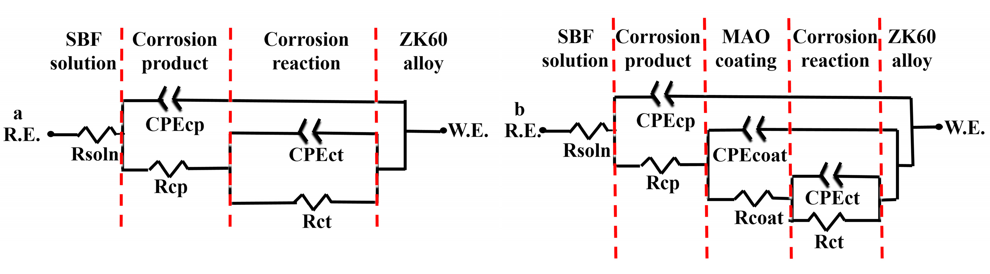
The Nyquist plots of both uncoated and coated samples after immersing in SBF for various amounts of time are presented in Figure 9. Equivalent circuits for fitting the uncoated and coated samples are shown in Figure 10. The non-ideal capacitive behavior of the coating is taken into account by using constant phase element (CPE) instead of capacitances in the model [53,54]. In the equivalent circuits, Rsoln is the SBF solution resistance, Rcp is the corrosion product resistance with constant phase element CPEcp, Rcoat is the coating resistance paralleled with constant phase element CPEcoat, and Rct is the reaction resistance paralleled with constant phase element CPEct. The use of a CPE was necessary due to the distribution of relaxation times resulting from heterogeneities at the electrode surface [55]. The impedance of the CPE is given by Equation (5) [56]:
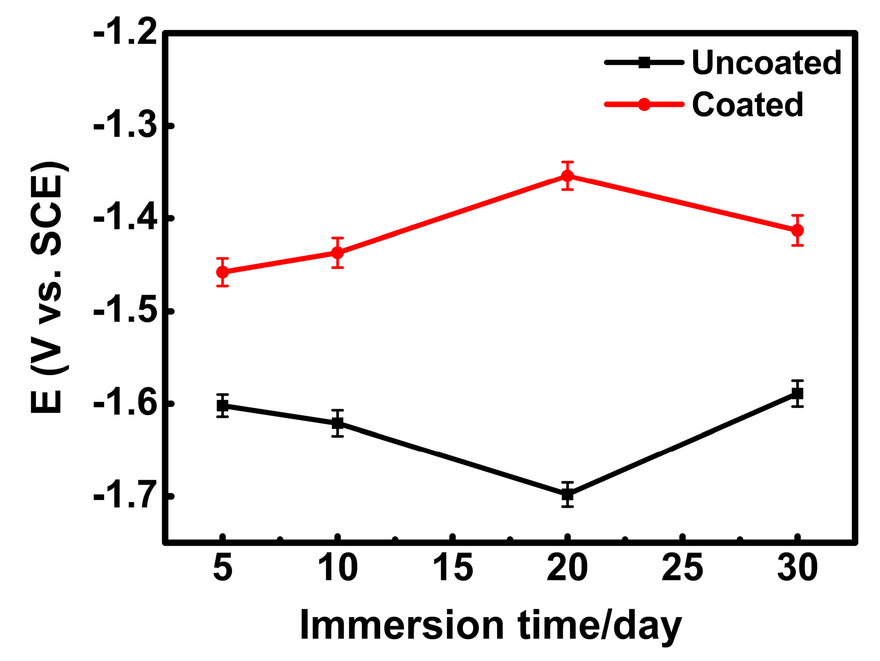
The fitting EIS results are listed in Table 3. Figure 11 shows the open circuit potentials for the uncoated and the coated samples after immersion for 30 days. The global impedances of the coated samples were much higher than those of the uncoated ones (Figure 9). This suggests that the MAO coating could effectively inhibit the degradation of the substrate. For the uncoated samples, the Rct value increased from day 5 to day 10 and from day 20 to day 30 (Table 3), indicating that the degradation and deposition were active simultaneously. For the coated samples, the Rct value increased from day 5 to day 20, and then decreased. The increase of the Rct value for the coated samples indicates that the deposition of the corrosion product layer inhibited the penetration of the SBF through the coating. With the continuous reaction between the solution and the coating, the thickness of the coating decreased with the increase of the corrosion product layer. So, the Rcoat decreased. However, the weight loss rate of the coated sample increased gradually (Figure 5), suggesting that the degradation of the coating was faster than the deposition of corrosion product. After immersion for 30 days, a large part of the coating dissolved in the solution and the substrate was exposed. Thus, the Rct value decreased again.
4. Discussion
4.1. Degradation Mechanism of Uncoated ZK60 Alloy
Li et al. [57] suggested a biocorrosion model that can be used to describe the corrosion process of Mg alloys. According to this concept, the degradation model of ZK60 Mg alloy in SBF is proposed as shown in Figure 12a. Xu et al. [18] indicated that uniform corrosion and localized corrosion are the two mechanisms during the degradation process. In the early stage of immersion, Mg encounters an anodic dissolution (Equation (2)), accompanied by the release of H2 and the Mg(OH)2 film formed on Mg alloy (Equations (3) and (4)). This is a uniform corrosion process, as shown in Figure 12a. In SBF, localized corrosion is mostly due to the penetration of Cl− ions from the solution. Lederer et al. [58] reveals that Cl− ions can not only damage the Mg(OH)2 film, but also corrode the Mg alloy. The reactions are suggested as follows:
Mg(OH)2 + 2Cl− → MgCl2 + 2OH−
Mg2+ + 2Cl− → MgCl2
The Cl− in SBF reacts with Mg(OH)2, and these reactions generate MgCl2 and OH−. Hence, the surface of the alloy is surrounded by a large amount of OH− (Figure 12b) [59]. Then, Ca2+ and HPO42− in SBF react with OH− (Figure 12c), as indicated by Equation (8) [60]:
Ca2+ + HPO42 − + OH− → Ca–P layer + H2O
As the uniform corrosion and the localized corrosion proceed, part of the sample decomposes into free particles in the solution (Figure 12d). In this way, Mg alloy is covered by corrosion products and exposed to the solution again and again, which results in unsteady EIS data (Table 3).
Zhang et al. [61] reported that the corrosion of Mg alloy is closely associated with the corrosion of alpha phase. Moreover, the intermetallic compound beta phase between magnesium and alloying elements itself is not readily corroded as a function of the cathode in galvanic corrosion. When the content of beta phase is high and its distribution is continuous, uniform, and fine, grains of alpha phase are almost entirely separated by beta phase, so the corrosion can hardly pass from one grain to another. In this way, beta phase acts as a barrier against corrosion. When beta phase is of lower content and its distribution is not continuous, corrosion diffuses easily. In this condition, the beta phase accelerates the galvanic corrosion. Beta phase (Mg7Zn3) is unable to distribute continuously in ZK60 because of the low solid solubility of their alloying elements in magnesium and the low content of Al. So, the corrosion process is accelerated, resulting in a decrease of corrosion resistance.
4.2. Degradation Mechanism of the Coated ZK60 Alloy
Gu et al. [19,35] suggested a degradation model of the MAO coating in SBF (Figure 13). Generally, the MAO coating consists of a porous layer and a dense layer. In the early stage of immersion, only the MgO from the coating reacts with the solution. The reaction is shown below:
MgO + H2 → Mg(OH)2
A certain amount of Mg(OH)2 transforms into MgCl2 (Equation (6)), leaving the OH− on the surface (Figure 13a). And then a Ca-P product layer forms since the OH− subsequently reacts with the other compounds and ions [62]. The following is the possible reaction:
3Ca2+ + Mg3(PO4)2 + 2HPO42− + 2OH− → Ca3Mg3(PO4)4 + 2H2O.
As the immersion test continues, SBF solution penetrates the loose layer, diffusing into and enlarging the micro-pores of the layer, thereby permitting the SBF’s penetration into the dense layer and even the substrate alloy (Figure 13b). Once the solution contacts the substrate, Mg reacts with the solution and produces Mg(OH)2 together with H2 (Equations (2)–(4)). When all the pores are penetrated, rapid degradation takes place (Figure 13c) and the coating is therefore dissolved (Figure 13d).
Therefore, a thick dense layer can inhibit the penetration of the SBF. Meanwhile, the smaller the pores, the more slowly they enlarge. Under such a condition (i.e., a thick dense layer with small pores), the Ca-P product layer covers the surface of the coating, which would inhibit the coating’s degradation. If the coating degrades as shown in Figure 13d, a large amount of Mg(OH)2 would be gained. Without the coating composition, Ca3Mg3(PO4)4 cannot be produced. The reactions in SBF would change into the ones in Figure 12a, then the degradation model of the coated samples in SBF would be the same as the uncoated samples.
5. Conclusions
Bio-ceramic coatings were fabricated on ZK60 Mg alloy through micro-arc oxidation, and both coated and uncoated samples were immersed in SBF for 30 days to study their degradation behavior. The main conclusions were drawn as follows:
(1) A porous coating prepared by MAO mainly consisted of MgO, Mg2SiO4, Mg3(PO4)2, and CaCO3 with a dense inner layer and a porous outer layer. The rough surface (Ra = 3.765 μm) of the coating was very hydrophilic, which favored cells’ adherence and growth.
(2) During the immersion period, the pH value of the SBF solution with coated samples was lower than that of uncoated samples, which indicates the coated samples showed a much lower rate of degradation. The second phase Mg7Zn3 in ZK60 led to the micro-couple corrosion between the second phase and the matrix metal, resulting in the decrease of corrosion resistance.
(3) After immersion for 5 days, corrosion product containing Ca and P was found on both samples, while the deposition was more active on the coated samples. With the decomposition of the coating, the Ca–P compounds disappeared in the late stage. EIS results indicated that the degradation rate of the coated sample decreased with the immersion time, and in the equivalent circuits the Rct value increased accordingly.
(4) Degradation models for the uncoated and coated samples in the SBF are proposed, which explain the degradation process and corrosion mechanism for the samples in different periods. The corrosion product of Ca3Mg3(PO4)4 can inhibit the coating from degrading, and the degradation rate of MAO coating depends on the thickness of the dense layer and the pore size.
Author Contributions
Z.-X.W. and L.X. conceived and designed the experiments; G.-Q.C. and L.X. performed the experiments; Z.-X.W. and S.L. analyzed the data; Z.-X.W., L.-Y.C., and S.L. wrote the paper.
Funding
This research was funded by Postgraduate Research & Practice Innovation Program of Jiangsu Province KYCX18_2317.
Acknowledgments
The authors would like to acknowledge a financial support provided by Postgraduate Research & Practice Innovation Program of Jiangsu Province. The authors also would like to acknowledge Instrumental Analysis Center of Jiangsu University of Science and Technology for providing technology support.
Conflicts of Interest
The authors declare no conflict of interest.
References
- Bian, D.; Zhou, W.; Deng, J.; Liu, Y.; Li, W.; Chu, X.; Xiu, P.; Cai, H.; Kou, Y.; Jiang, B.; et al. Development of magnesium-based biodegradable metals with dietary trace element germanium as orthopaedic implant applications. Acta Biomater. 2017, 64, 421–436. [Google Scholar] [CrossRef] [PubMed]
- Zheng, Y.; Lai, L.; Liu, W.; Jiang, H.; Wang, X. Recent advances in biomedical applications of fluorescent gold nanoclusters. Adv. Colloid Interface Sci. 2017, 242, 1–16. [Google Scholar] [CrossRef] [PubMed]
- Gao, Y.; Yerokhin, A.; Matthews, A. Mechanical behaviour of cp-magnesium with duplex hydroxyapatite and PEO coatings. Mater. Sci. Eng. C 2015, 49, 190–200. [Google Scholar] [CrossRef] [PubMed]
- Xu, L.; Shi, X.; Ouyang, C.; Liu, W. In vitro apatite formation, protein adsorption and initial osteoblast responses on titanium surface enriched with magnesium. Rare Met. Mater. Eng. 2017, 46, 1512–1517. [Google Scholar]
- Ehtemam-Haghighi, S.; Cao, G.; Zhang, L.-C. Nanoindentation study of mechanical properties of Ti based alloys with Fe and Ta additions. J. Alloys Compd. 2017, 692, 892–897. [Google Scholar] [CrossRef]
- Staiger, M.P.; Pietak, A.M.; Huadmai, J.; Dias, G. Magnesium and its alloys as orthopedic biomaterials: A review. Biomaterials 2006, 27, 1728–1734. [Google Scholar] [CrossRef] [PubMed]
- Bakhsheshi-Rad, H.R.; Hamzah, E.; Daroonparvar, M.; Abdul Kadir, M.R.; Kasiri-Asgarani, M.; Staiger, M.P. Enhancement of corrosion resistance and mechanical properties of Mg-1.2Ca-2Bi via a hybrid silicon-biopolymer coating system. Surf. Coat. Technol. 2016, 301, 133–139. [Google Scholar] [CrossRef]
- Liu, L.H.; Yang, C.; Wang, F.; Qu, S.G.; Li, X.Q.; Zhang, W.W.; Li, Y.Y.; Zhang, L.C. Ultrafine grained Ti-based composites with ultrahigh strength and ductility achieved by equiaxing microstructure. Mater. Des. 2015, 79, 1–5. [Google Scholar] [CrossRef]
- Calin, M.; Zhang, L.C.; Eckert, J. Tailoring of microstructure and mechanical properties of a Ti-based bulk metallic glass-forming alloy. Scr. Mater. 2007, 57, 1101–1104. [Google Scholar] [CrossRef]
- Bakhsheshi-Rad, H.R.; Hamzah, E.; Ismail, A.F.; Aziz, M.; Daroonparvar, M.; Saebnoori, E.; Chami, A. In vitro degradation behavior, antibacterial activity and cytotoxicity of TiO2-MAO/ZnHA composite coating on Mg alloy for orthopedic implants. Surf. Coat. Technol. 2018, 334, 450–460. [Google Scholar] [CrossRef]
- Hornberger, H.; Virtanen, S.; Boccaccini, A.R. Biomedical coatings on magnesium alloys—A review. Acta Biomater. 2012, 8, 2442–2455. [Google Scholar] [CrossRef] [PubMed]
- Liu, J.; Willför, S.; Xu, C. A review of bioactive plant polysaccharides: Biological activities, functionalization, and biomedical applications. Bioact. Carbohydr. Diet. Fibre 2015, 5, 31–61. [Google Scholar] [CrossRef]
- Li, X.; Liu, X.; Wu, S.; Yeung, K.W.K.; Zheng, Y.; Chu, P.K. Design of magnesium alloys with controllable degradation for biomedical implants: From bulk to surface. Acta Biomater. 2016, 45, 2–30. [Google Scholar] [CrossRef] [PubMed]
- Witte, F. Reprint of: The history of biodegradable magnesium implants: A review. Acta Biomater. 2015, 23, S28–S40. [Google Scholar] [CrossRef] [PubMed]
- Jiang, H.; Wang, J.; Chen, M.; Liu, D. Biological activity evaluation of magnesium fluoride coated Mg-Zn-Zr alloy in vivo. Mater. Sci. Eng. C 2017, 75, 1068–1074. [Google Scholar] [CrossRef] [PubMed]
- Li, L.; Gao, J.; Wang, Y. Evaluation of cyto-toxicity and corrosion behavior of alkali-heat-treated magnesium in simulated body fluid. Surf. Coat. Technol. 2004, 185, 92–98. [Google Scholar] [CrossRef]
- Guan, R.; Cipriano, A.F.; Zhao, Z.; Lock, J.; Tie, D.; Zhao, T.; Cui, T.; Liu, H. Development and evaluation of a magnesium-zinc-strontium alloy for biomedical applications—Alloy processing, microstructure, mechanical properties, and biodegradation. Mater. Sci. Eng. C 2013, 33, 3661–3669. [Google Scholar] [CrossRef] [PubMed]
- Zhao, X.; Shi, L.; Xu, J. Mg-Zn-Y alloys with long-period stacking ordered structure: In vitro assessments of biodegradation behavior. Mater. Sci. Eng. C 2013, 33, 3627–3637. [Google Scholar] [CrossRef] [PubMed]
- Gu, Y.; Bandopadhyay, S.; Chen, C.; Ning, C.; Guo, Y. Long-term corrosion inhibition mechanism of microarc oxidation coated AZ31 Mg alloys for biomedical applications. Mater. Des. 2013, 46, 66–75. [Google Scholar] [CrossRef]
- Shizhao, S.; Yanze, B.; Minfang, C.; Debao, L.; Chen, Y.; Yan, H. Degradation mechanism of the biomedical Mg-3Zn-0.5Zr alloy in a simulated physiological environment containing different anions. Rare Met. Mater. Eng. 2016, 45, 2827–2834. [Google Scholar] [CrossRef]
- McEntire, B.J.; Bal, B.S.; Rahaman, M.N.; Chevalier, J.; Pezzotti, G. Ceramics and ceramic coatings in orthopaedics. J. Eur. Ceram. Soc. 2015, 35, 4327–4369. [Google Scholar] [CrossRef]
- Wang, L.; Xie, L.; Lv, Y.; Zhang, L.-C.; Chen, L.; Meng, Q.; Qu, J.; Zhang, D.; Lu, W. Microstructure evolution and superelastic behavior in Ti-35Nb-2Ta-3Zr alloy processed by friction stir processing. Acta Mater. 2017, 131, 499–510. [Google Scholar] [CrossRef]
- Wang, L.; Xie, L.; Zhang, L.-C.; Chen, L.; Ding, Z.; Lv, Y.; Zhang, W.; Lu, W.; Zhang, D. Microstructure evolution and superelasticity of layer-like NiTiNb porous metal prepared by eutectic reaction. Acta Mater. 2018, 143, 214–226. [Google Scholar] [CrossRef]
- Yang, K.; Tan, L. Control of biodegradation of magnesium (Mg) alloys for medical applications. Corros. Prev. Magnes. Alloys 2013, 509–543. [Google Scholar]
- Yazici, M.; Gulec, A.E.; Gurbuz, M.; Gencer, Y.; Tarakci, M. Biodegradability and antibacterial properties of MAO coatings formed on Mg-Sr-Ca alloys in an electrolyte containing Ag doped hydroxyapatite. Thin Solid Films 2017, 644, 92–98. [Google Scholar] [CrossRef]
- Lei, J.; Shi, C.; Zhou, S.; Gu, Z.; Zhang, L.-C. Enhanced corrosion and wear resistance properties of carbon fiber reinforced Ni-based composite coating by laser cladding. Surf. Coat. Technol. 2018, 334, 274–285. [Google Scholar] [CrossRef]
- Chen, L.-Y.; Xu, T.; Lu, S.; Wang, Z.-X.; Chen, S.; Zhang, L.-C. Improved hardness and wear resistance of plasma sprayed nanostructured NiCrBSi coating via short-time heat treatment. Surf. Coat. Technol. 2018, 350, 436–444. [Google Scholar] [CrossRef]
- Gray, J.E.; Luan, B. Protective coatings on magnesium and its alloys—A critical review. J. Alloys Compd. 2002, 336, 88–113. [Google Scholar] [CrossRef]
- Rokosz, K.; Hryniewicz, T.; Gaiaschi, S.; Chapon, P.; Raaen, S.; Pietrzak, K.; Malorny, W.; Salvador Fernandes, J. Characterization of porous phosphate coatings enriched with magnesium or zinc on CP titanium grade 2 under DC plasma electrolytic oxidation. Metals 2018, 8, 112. [Google Scholar] [CrossRef]
- Shao, L.; Li, H.; Jiang, B.; Liu, C.; Gu, X.; Chen, D.; Shao, L.; Li, H.; Jiang, B.; Liu, C.; et al. Comparative study of corrosion behavior of hard anodized and micro-arc oxidation coatings on 7050 aluminum alloy. Metals 2018, 8, 165. [Google Scholar] [CrossRef]
- Hakimizad, A.; Raeissi, K.; Santamaria, M.; Asghari, M. Effects of pulse current mode on plasma electrolytic oxidation of 7075 Al in Na2WO4 containing solution: From unipolar to soft-sparking regime. Electrochim. Acta 2018, 284, 618–629. [Google Scholar] [CrossRef]
- Wilke, B.M.; Zhang, L.; Li, W.; Ning, C.; Chen, C.; Gu, Y. Corrosion performance of MAO coatings on AZ31 Mg alloy in simulated body fluid vs. Earle’s Balance Salt Solution. Appl. Surf. Sci. 2016, 363, 328–337. [Google Scholar] [CrossRef]
- Sankara Narayanan, T.S.N.; Park, I.S.; Lee, M.H. Strategies to improve the corrosion resistance of microarc oxidation (MAO) coated magnesium alloys for degradable implants: Prospects and challenges. Prog. Mater. Sci. 2014, 60, 1–71. [Google Scholar] [CrossRef]
- Antunes, R.A.; de Oliveira, M.C.L. Corrosion fatigue of biomedical metallic alloys: Mechanisms and mitigation. Acta Biomater. 2012, 8, 937–962. [Google Scholar] [CrossRef] [PubMed]
- Gu, Y.; Chen, C.; Bandopadhyay, S.; Ning, C.; Zhang, Y.; Guo, Y. Corrosion mechanism and model of pulsed DC microarc oxidation treated AZ31 alloy in simulated body fluid. Appl. Surf. Sci. 2012, 258, 6116–6126. [Google Scholar] [CrossRef]
- Lin, X.; Yang, X.; Tan, L.; Li, M.; Wang, X.; Zhang, Y.; Yang, K.; Hu, Z.; Qiu, J. In vitro degradation and biocompatibility of a strontium-containing micro-arc oxidation coating on the biodegradable ZK60 magnesium alloy. Appl. Surf. Sci. 2014, 288, 718–726. [Google Scholar] [CrossRef]
- Zhang, S.F.; Zhang, R.F.; Li, W.K.; Li, M.S.; Yang, G.L. Effects of tannic acid on properties of anodic coatings obtained by micro arc oxidation on AZ91 magnesium alloy. Surf. Coat. Technol. 2012, 207, 170–176. [Google Scholar] [CrossRef]
- Rama Krishna, L.; Poshal, G.; Jyothirmayi, A.; Sundararajan, G. Compositionally modulated CGDS + MAO duplex coatings for corrosion protection of AZ91 magnesium alloy. J. Alloys Compd. 2013, 578, 355–361. [Google Scholar] [CrossRef]
- Rad, H.R.B.; Idris, M.H.; Kadir, M.R.A.; Farahany, S. Microstructure analysis and corrosion behavior of biodegradable Mg-Ca implant alloys. Mater. Des. 2012, 33, 88–97. [Google Scholar] [CrossRef]
- Zhang, S.; Zhang, X.; Zhao, C.; Li, J.; Song, Y.; Xie, C.; Tao, H.; Zhang, Y.; He, Y.; Jiang, Y.; et al. Research on an Mg-Zn alloy as a degradable biomaterial. Acta Biomater. 2010, 6, 626–640. [Google Scholar] [CrossRef] [PubMed]
- Sedelnikova, M.; Komarova, E.; Sharkeev, Y.; Tolkacheva, T.; Sheikin, V.; Egorkin, V.; Mashtalyar, D.; Kazakbaeva, A.; Schmidt, J. Characterization of the micro-arc coatings containing β-tricalcium phosphate particles on Mg-0.8Ca alloy. Metals 2018, 8, 238. [Google Scholar] [CrossRef]
- Mogha, N.K.; Sahu, V.; Sharma, M.; Sharma, R.K.; Masram, D.T. Biocompatible ZrO2-reduced graphene oxide immobilized AChE biosensor for chlorpyrifos detection. Mater. Des. 2016, 111, 312–320. [Google Scholar] [CrossRef]
- Zhang, S.; Bi, Y.; Li, J.; Wang, Z.; Yan, J.; Song, J.; Sheng, H.; Guo, H.; Li, Y. Biodegradation behavior of magnesium and ZK60 alloy in artificial urine and rat models. Bioact. Mater. 2017, 2, 53–62. [Google Scholar] [CrossRef] [PubMed]
- Jin, W.; Wang, G.; Lin, Z.; Feng, H.; Li, W.; Peng, X.; Qasim, A.M.; Chu, P.K. Corrosion resistance and cytocompatibility of tantalum-surface-functionalized biomedical ZK60 Mg alloy. Corros. Sci. 2017, 114, 45–56. [Google Scholar] [CrossRef]
- Chen, Y.; Zhang, J.; Dai, N.; Qin, P.; Attar, H.; Zhang, L.-C. Corrosion behaviour of selective laser melted Ti-TiB biocomposite in simulated body fluid. Electrochim. Acta 2017, 232, 89–97. [Google Scholar] [CrossRef]
- Cheng, Z.; Lian, J.; Hui, Y.; Li, G. Biocompatible DCPD coating formed on AZ91D magnesium alloy by chemical deposition and its corrosion behaviors in SBF. J. Bionic Eng. 2014, 11, 610–619. [Google Scholar] [CrossRef]
- Lu, H.B.; Zhang, L.C.; Gebert, A.; Schultz, L. Pitting corrosion of Cu-Zr metallic glasses in hydrochloric acid solutions. J. Alloys Compd. 2008, 462, 60–67. [Google Scholar] [CrossRef]
- Cui, X.-J.; Ping, J.; Zhang, Y.-J.; Jin, Y.-Z.; Zhang, G.-A. Structure and properties of newly designed MAO/TiN coating on AZ31B Mg alloy. Surf. Coat. Technol. 2017, 328, 319–325. [Google Scholar] [CrossRef]
- Pan, L.; Yoon, R.-H. Effects of elctrolytes on the stability of wetting films: Implications on seawater flotation. Miner. Eng. 2018, 122, 1–9. [Google Scholar] [CrossRef]
- Li, Y.; Lu, F.; Li, H.; Zhu, W.; Pan, H.; Tan, G.; Lao, Y.; Ning, C.; Ni, G. Corrosion mechanism of micro-arc oxidation treated biocompatible AZ31 magnesium alloy in simulated body fluid. Prog. Nat. Sci. Mater. Int. 2014, 24, 516–522. [Google Scholar] [CrossRef]
- Kim, H.-W.; Knowles, J.C.; Kim, H.-E. Hydroxyapatite/poly(ε-caprolactone) composite coatings on hydroxyapatite porous bone scaffold for drug delivery. Biomaterials 2004, 25, 1279–1287. [Google Scholar] [CrossRef] [PubMed]
- Mohd Yusoff, M.F.; Abdul Kadir, M.R.; Iqbal, N.; Hassan, M.A.; Hussain, R. Dipcoating of poly (ε-caprolactone)/hydroxyapatite composite coating on Ti6Al4V for enhanced corrosion protection. Surf. Coat. Technol. 2014, 245, 102–107. [Google Scholar] [CrossRef]
- Curioni, M.; Salamone, L.; Scenini, F.; Santamaria, M.; Di Natale, M. A mathematical description accounting for the superfluous hydrogen evolution and the inductive behaviour observed during electrochemical measurements on magnesium. Electrochim. Acta 2018, 274, 343–352. [Google Scholar] [CrossRef]
- Akbari, E.; Di Franco, F.; Ceraolo, P.; Raeissi, K.; Santamaria, M.; Hakimizad, A. Electrochemically-induced TiO2 incorporation for enhancing corrosion and tribocorrosion resistance of PEO coating on 7075 Al alloy. Corros. Sci. 2018. [Google Scholar] [CrossRef]
- Wang, Z.B.; Hu, H.X.; Zheng, Y.G.; Ke, W.; Qiao, Y.X. Comparison of the corrosion behavior of pure titanium and its alloys in fluoride-containing sulfuric acid. Corros. Sci. 2016, 103, 50–65. [Google Scholar] [CrossRef]
- Qiao, Y.X.; Zheng, Y.G.; Ke, W.; Okafor, P.C. Electrochemical behaviour of high nitrogen stainless steel in acidic solutions. Corros. Sci. 2009, 51, 979–986. [Google Scholar] [CrossRef]
- Li, Z.; Gu, X.; Lou, S.; Zheng, Y. The development of binary Mg-Ca alloys for use as biodegradable materials within bone. Biomaterials 2008, 29, 1329–1344. [Google Scholar] [CrossRef] [PubMed]
- Lederer, S.; Lutz, P.; Fürbeth, W. Surface modification of Ti 13Nb 13Zr by plasma electrolytic oxidation. Surf. Coat. Technol. 2018, 335, 62–71. [Google Scholar] [CrossRef]
- Pan, Y.K.; Chen, C.Z.; Wang, D.G.; Lin, Z.Q. Preparation and bioactivity of micro-arc oxidized calcium phosphate coatings. Mater. Chem. Phys. 2013, 141, 842–849. [Google Scholar] [CrossRef]
- García Rodenas, L.; Palacios, J.M.; Apella, M.C.; Morando, P.J.; Blesa, M.A. Surface properties of various powdered hydroxyapatites. J. Colloid Interface Sci. 2005, 290, 145–154. [Google Scholar] [CrossRef] [PubMed]
- Zhang, E.; Yin, D.; Xu, L.; Yang, L.; Yang, K. Microstructure, mechanical and corrosion properties and biocompatibility of Mg–Zn–Mn alloys for biomedical application. Mater. Sci. Eng. C 2009, 29, 987–993. [Google Scholar] [CrossRef]
- Lin, X.; Tan, L.; Zhang, Q.; Yang, K.; Hu, Z.; Qiu, J.; Cai, Y. The in vitro degradation process and biocompatibility of a ZK60 magnesium alloy with a forsterite-containing micro-arc oxidation coating. Acta Biomater. 2013, 9, 8631–8642. [Google Scholar] [CrossRef] [PubMed]
Figure 1.
(a) Surface and (b) cross-sectional morphologies of micro-arc oxidation (MAO) coating.

Figure 2.
X-ray diffraction (XRD) pattern of the MAO coating.

Figure 3.
(a) Surface roughness of the MAO coating and (b) water contact angle of the MAO coating.

Figure 4.
Changes in the pH values of the simulated blood fluids (SBFs) immersed with different samples over time.
Figure 4.
Changes in the pH values of the simulated blood fluids (SBFs) immersed with different samples over time.

Figure 5.
Changes in weight loss rate of the samples over time.
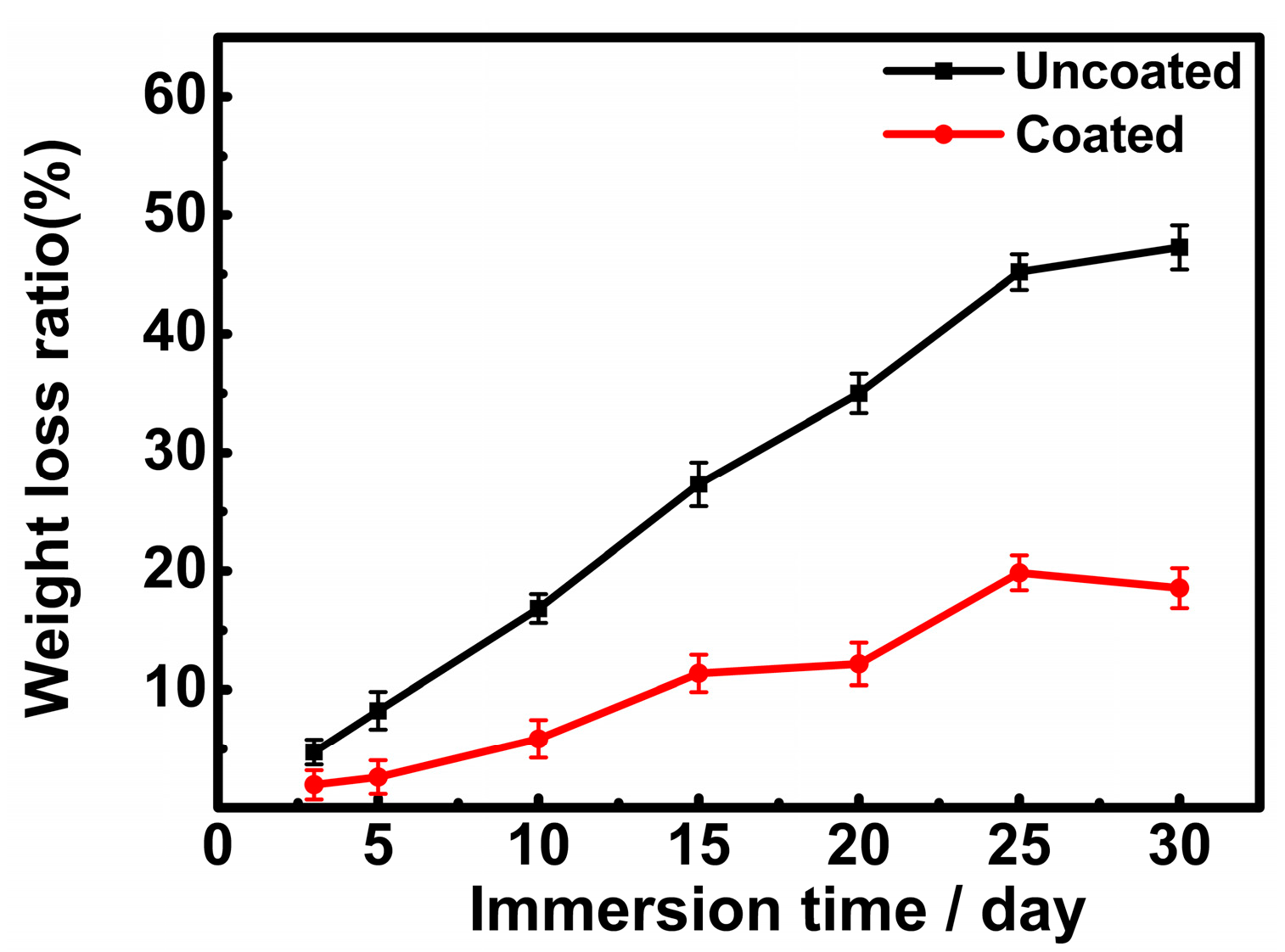
Figure 6.
Morphologies of the uncoated and coated samples after immersion for 30 days: (a) 5 days, (b) 10 days, (c) 20 days, and (d) 30 days for uncoated sample, and (e) 5 days, (f) 10 days, (g) 20 days, and (h) 30 days for MAO coated sample, respectively.
Figure 6.
Morphologies of the uncoated and coated samples after immersion for 30 days: (a) 5 days, (b) 10 days, (c) 20 days, and (d) 30 days for uncoated sample, and (e) 5 days, (f) 10 days, (g) 20 days, and (h) 30 days for MAO coated sample, respectively.

Figure 7.
XRD patterns of (a) the uncoated and (b) the MAO coated samples after immersion for 30 days.
Figure 7.
XRD patterns of (a) the uncoated and (b) the MAO coated samples after immersion for 30 days.
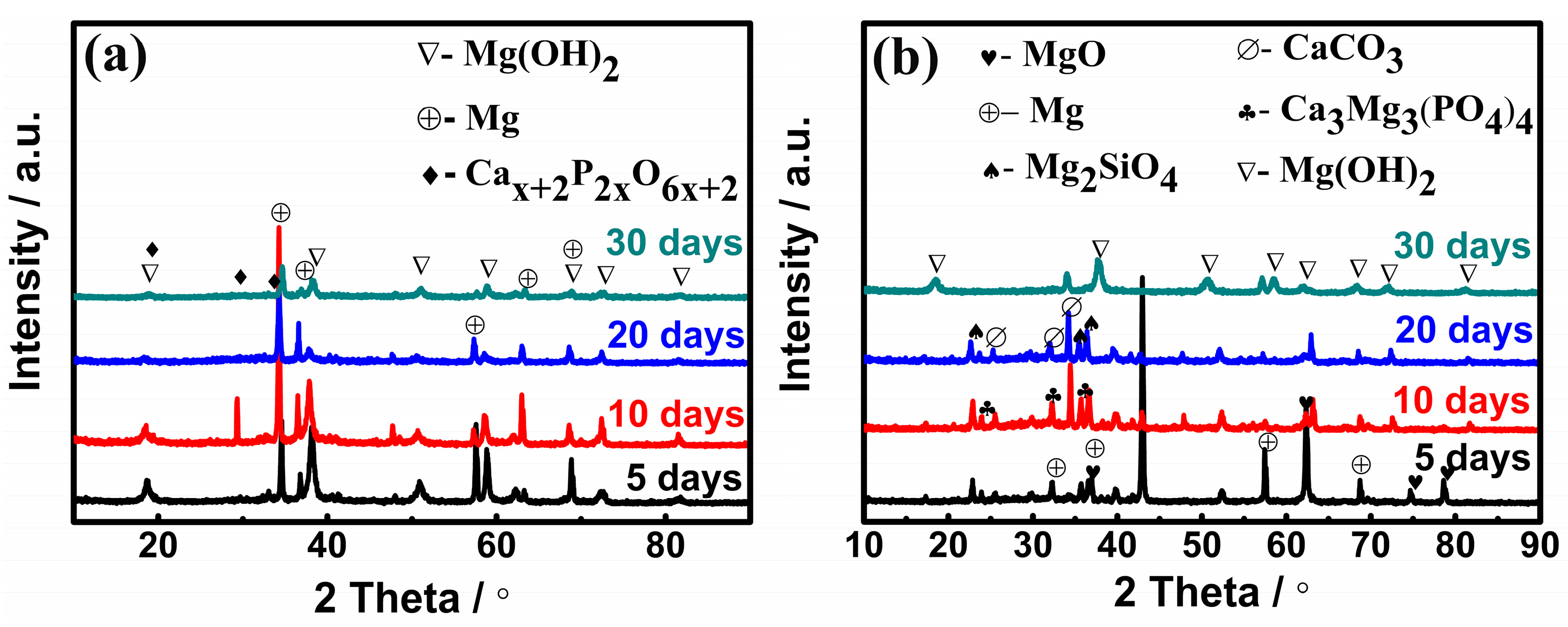
Figure 8.
Fourier transform infrared spectroscopy (FTIR) of corrosion products on samples: (a) uncoated (b) MAO coated.
Figure 8.
Fourier transform infrared spectroscopy (FTIR) of corrosion products on samples: (a) uncoated (b) MAO coated.

Figure 9.
Nyquist plots of (a) the uncoated and (b) the MAO coated samples.

Figure 10.
Equivalent circuits for fitting the impedance data of (a) the uncoated and (b) the MAO coated samples in SBF. CPE: constant phase element.
Figure 10.
Equivalent circuits for fitting the impedance data of (a) the uncoated and (b) the MAO coated samples in SBF. CPE: constant phase element.

Figure 11.
The evolution of open circuit potentials for the uncoated and the coated samples after immersion for 30 days.
Figure 11.
The evolution of open circuit potentials for the uncoated and the coated samples after immersion for 30 days.

Figure 12.
Degradation models of the uncoated samples upon immersion in the SBF. (a) uniform corrosion stage, (b) localized corrosion stage, (c) Ca-P formation stage, and (d) local decomposition stage.
Figure 12.
Degradation models of the uncoated samples upon immersion in the SBF. (a) uniform corrosion stage, (b) localized corrosion stage, (c) Ca-P formation stage, and (d) local decomposition stage.
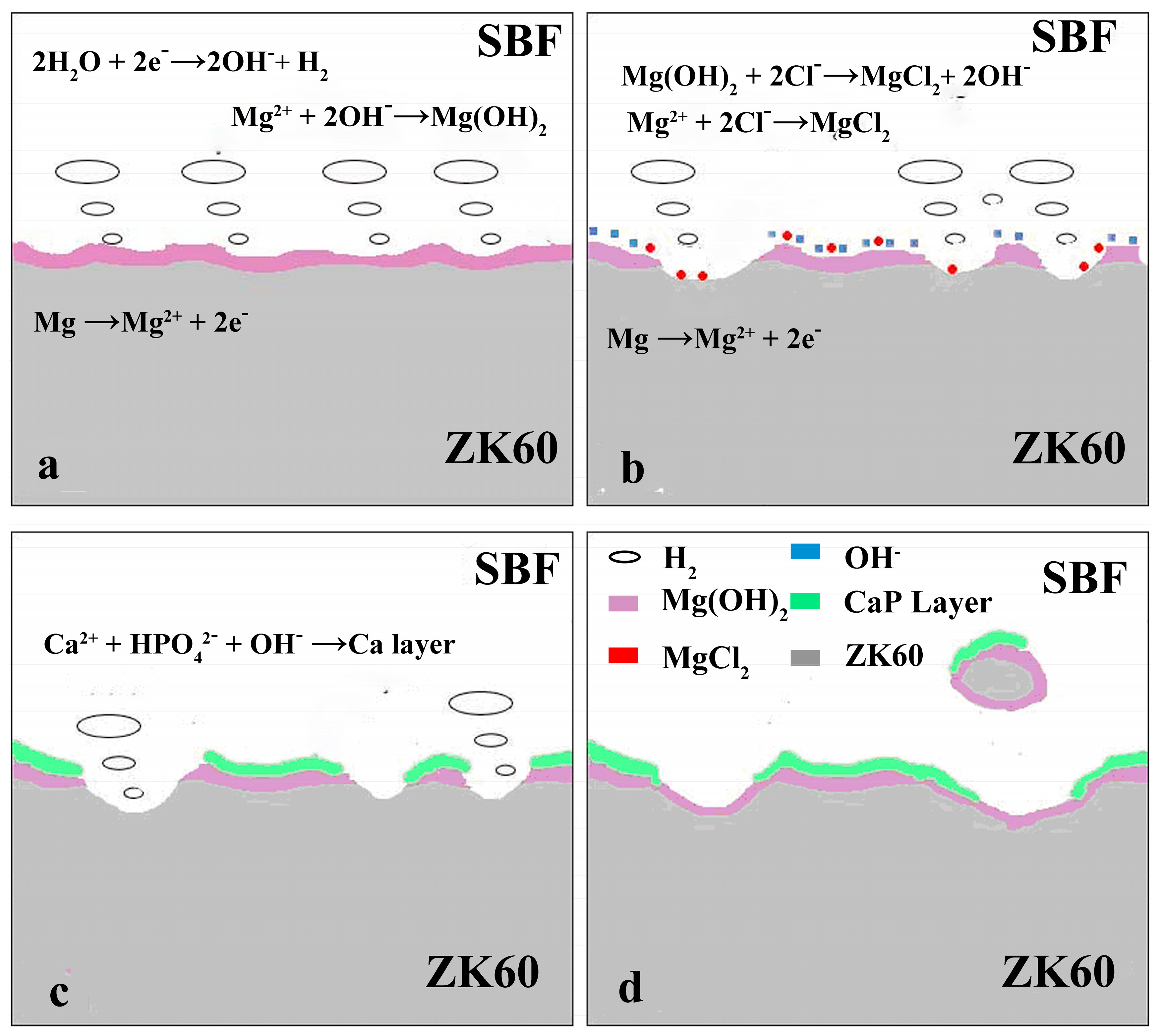
Figure 13.
Degradation models of the MAO coated samples upon immersion in the SBF: (a) surface corrosion stage, (b) micro-pore enlargement stage, (c) coating degradation stage, and (d) coating decomposition stage.
Figure 13.
Degradation models of the MAO coated samples upon immersion in the SBF: (a) surface corrosion stage, (b) micro-pore enlargement stage, (c) coating degradation stage, and (d) coating decomposition stage.


Table 1.
Ion concentrations of simulated body fluid (SBF) and blood plasma (mmol/L).
| Solution | Na+ | K+ | Mg2+ | Ca2+ | Cl− | HCO3− | HPO42− | SO42− |
|---|---|---|---|---|---|---|---|---|
| SBF | 142.0 | 5.0 | 1.5 | 2.5 | 148.8 | 4.2 | 1.0 | 0.5 |
| Blood Plasma | 142.0 | 5.0 | 1.5 | 2.5 | 103.0 | 27.0 | 1.0 | 0.5 |
Table 2.
Reagents and doses for 1000 mL SBF.
| Reagent | NaCl | NaHCO3 | KCl | K2HPO4·3H2O | MgCl2·6H2O | 1.0 M-HCl | Na2SO4 |
|---|---|---|---|---|---|---|---|
| Quantity | 8.035 g | 0.355 g | 0.225 g | 0.231 g | 0.311 g | 39 mL | 0.072 g |
Table 3.
Electrochemical parameters of the uncoated and coated samples after immersion in SBF for various amounts of time.
Table 3.
Electrochemical parameters of the uncoated and coated samples after immersion in SBF for various amounts of time.
| Sample | Immersion Time (Days) | Rsoln (Ω·cm²) | Qcp (Ω−1·cm−² sn) | n | Rcp (Ω·cm²) | Qcoat (Ω−1·cm−² sn) | n | Rcoat (Ω·cm²) | Qct (Ω−1·cm−² sn) | n | Rct (Ω·cm²) |
|---|---|---|---|---|---|---|---|---|---|---|---|
| Uncoated | 5 | 36 | 2.10 × 10⁻⁴ | 0.89 | 86.73 | - | - | - | 3.65 × 10⁻⁶ | 0.86 | 2056 |
| 10 | 52 | 1.33 × 10⁻⁵ | 0.91 | 122.4 | - | - | - | 3.59 × 10⁻⁶ | 0.80 | 3454 | |
| 20 | 43 | 8.57 × 10⁻⁴ | 0.83 | 46.47 | - | - | - | 4.18 × 10⁻⁵ | 0.88 | 579.3 | |
| 30 | 56 | 2.36 × 10⁻⁶ | 0.84 | 1206 | - | - | - | 1.50 × 10⁻⁷ | 0.95 | 4496 | |
| MAO Coated | 5 | 58 | 5.12 × 10⁻⁶ | 0.92 | 2124 | 3.88 × 10⁻⁷ | 0.85 | 2081 | 4.43 × 10⁻⁶ | 0.80 | 2.78 × 10⁴ |
| 10 | 42 | 2.30 × 10⁻⁶ | 0.86 | 8205 | 1.82 × 10⁻⁶ | 0.89 | 272.3 | 2.75 × 10⁻⁶ | 0.82 | 4.03 × 10⁴ | |
| 20 | 47 | 3.52 × 10⁻⁷ | 0.87 | 1.08 × 10⁴ | 4.18 × 10⁻⁴ | 0.90 | 0.02 | 2.35 × 10⁻⁷ | 0.89 | 6.73 × 10⁴ | |
| 30 | 75 | 4.65 × 10⁻⁶ | 0.81 | 6587 | 3.25 × 10⁻⁴ | 0.82 | 0.53 | 8.69 × 10⁻⁶ | 0.81 | 1.39 × 10⁴ |
© 2018 by the authors. Licensee MDPI, Basel, Switzerland. This article is an open access article distributed under the terms and conditions of the Creative Commons Attribution (CC BY) license (http://creativecommons.org/licenses/by/4.0/).
Share and Cite
MDPI and ACS Style
Wang, Z.-X.; Chen, G.-Q.; Chen, L.-Y.; Xu, L.; Lu, S. Degradation Behavior of Micro-Arc Oxidized ZK60 Magnesium Alloy in a Simulated Body Fluid. Metals 2018, 8, 724. https://doi.org/10.3390/met8090724
AMA Style
Wang Z-X, Chen G-Q, Chen L-Y, Xu L, Lu S. Degradation Behavior of Micro-Arc Oxidized ZK60 Magnesium Alloy in a Simulated Body Fluid. Metals. 2018; 8(9):724. https://doi.org/10.3390/met8090724
Chicago/Turabian StyleWang, Ze-Xin, Guan-Qun Chen, Liang-Yu Chen, Lei Xu, and Sheng Lu. 2018. "Degradation Behavior of Micro-Arc Oxidized ZK60 Magnesium Alloy in a Simulated Body Fluid" Metals 8, no. 9: 724. https://doi.org/10.3390/met8090724
Note that from the first issue of 2016, this journal uses article numbers instead of page numbers. See further details here.