Study of Formed Oxides in IN718 Alloy during the Fabrication by Selective Laser Melting and Electron Beam Melting

1
Faculty of Engineering, Hokkaido University, N13W8 Kita-ku, Sapporo 060-8268, Japan
2
Department of Mechanical Engineering, Tokyo Metropolitan University, 1-1 Minami-Osawa, Hachioji-Shi, Tokyo 192-0397, Japan
*
Author to whom correspondence should be addressed.
Metals 2019, 9(1), 19; https://doi.org/10.3390/met9010019
Submission received: 14 November 2018
/
Revised: 16 December 2018
/
Accepted: 19 December 2018
/
Published: 24 December 2018
(This article belongs to the Special Issue Advances in Selective Laser Melting)
Abstract
:This study confirmed that Al2O3 particles were formed in IN718 alloys during the fabrication by both selective laser melting (SLM) and electron beam melting (EBM). Different heat pattern and atmospheres in SLM and EBM result in different distribution and volume fraction of Al2O3 particles. The Al2O3 oxides would act as nucleation sites for the precipitation of Nb/Ti carbides, leading to the formation of unique core-shell composites with Al2O3 in the center and Ti/Nb at the periphery. In order to investigate the oxygen content introduced during SLM and EBM, the volume fraction of Al2O3 formed in spark plasm sintering (SPS)-fabricated substrate, by consolidating the pre-oxidized IN718 raw powders at 800 °C, was utilized. The oxygen contents introduced to IN718 substrates during SLM and EBM fabrication were calculated to be 0.030 wt% and 0.099 wt%, respectively.
1. Introduction
Additive manufacturing (AM) is a novel materials fabrication process which can allow direct molding of raw powders into arbitrary configurations mapped out by 3D CAD (computer-aided design) data [1,2,3]. During fabrication, layers of fine metal or alloy powders are deposited by powder feeding and a high-power heat source fully melts the powders instantaneously. The process of AM technologies on the industrial production today splits broadly into two types, based on the difference of the heat source, namely, selective laser melting (SLM) and electron beam melting (EBM), where a laser beam and an electron beam are used as heat source, respectively [4]. Both the SLM and EBM processes are capable of fabricating fully dense metallic parts with high dimensional precision and superior surface integrity [2,5]. In addition, as claimed by Kuo et al. [6], AM technologies are able to suppress the formation of prior particle boundary (PPB) precipitations owing to the full melting of powders by the high-energy heat source. PPB precipitations result from powder surface contamination and widely exist in alloys after fabrication by traditional powder metallurgy technologies, such as hot isostatic pressing (HIP), and bring detrimental effects on mechanical properties as a possible source of brittle fracture [7,8].
So far, a large amount of prealloyed powders have been applied for AM technologies, including Ni-based alloy powders [9]. Among Ni-based alloys, IN718 is widely employed in many high-performance components in gas turbines, spacecraft, and nuclear reactors by virtue of an improved balance of mechanical properties and corrosion/oxidation resistance at elevated temperatures [10]. With the endless updating of design in industry, many structure components with complex configurations are proposed and whipped into service rapidly. In addition to a favorable mechanical performance, a high demand on dimensional precision and fabrication efficiency is necessary for the components. However, because a high hardness is maintained in broad temperatures for the majority of Ni-based alloys strengthened by solid-solution strengthening and precipitation strengthening of D022 ordered γ″ and/or L12 ordered γ′ precipitates, these kinds of Ni-based alloys are difficult to manufacture by conventional machining methods with low cost and high efficiency [11,12]. Thus, AM technologies have been focused on fabricating Ni-based alloys, and several alloys, such as IN718, have been successfully fabricated by AM technologies [13,14,15,16,17].
However, even though AM technologies could mitigate the PPB precipitations as mentioned above, raw powder surface with a high surface area is easily contaminated during AM process and handling. A high vacuum (10−4–10−5 mbar) (for EBM system) or an inert atmosphere (for SLM system) is used in AM operation [2,3], the impurity elements such as oxygen are difficult to remove from the chamber of SLM/EBM and easy to react with powders to form oxides at high temperatures over 1200 °C during AM processes, particularly for the powders which contain elements with a high affinity to oxygen and nitrogen gases. Thus, oxides formed on raw powders during AM process must generate residuals in AM-fabricated alloys, which will bring a certain influence on microstructure and mechanical properties [18,19]. However, thus far, no detailed report on the residuals in AM-fabricated Ni-based alloys has been presented, and how much oxygen content would be introduced into fabricated bulk alloys during AM process is still not clear. In the current work, the residuals/oxides formed in AM-fabricated IN718 Ni-based alloys were examined, in which the microstructural difference resulting from heat source was illustrated through observing SLM- and EBM-fabricated IN718 alloys. To perform a systematic study on the evolution of the oxides from powder surface contaminations to the residuals in alloy substrates, pre-oxidized IN718 raw powders were consolidated by SPS in order to examine the effect of pre-formed oxides on the microstructure of the bulk alloy. Besides, the oxygen contents introduced into IN718 substrates, during SLM and EBM fabrication, were quantitatively analyzed by comparing the SPS results.
2. Materials and Experimental Procedure
The prealloyed IN718 Ni-based powders were prepared by vacuum melting and gas atomized into a spherical shape with a mean particle size of 60 μm. The practical chemical compositions of used powders are given in Table 1, in which the metal elements were measured by inductively coupled plasma (ICP), and oxygen was measured by fusion method. Corresponding abbreviations are utilized to define each kind of the powders used in each fabrication. SLM process for IN718 was conducted by GmbH Electro Optical Systems (EOS) in 99.9999% argon. In the case of EBM, Arcam A2X EBM machine with a tungsten filament was utilized to fabricate IN718 specimens in vacuum. We used the default standard processing parameters developed by EOS and Arcam companies to operate the SLM and EBM processes, respectively. The cubes made by both SLM and EBM were set to the same size of 35 mm × 35 mm × 35 mm. After the SLM/EBM processes, test specimens were cut from the AM cubes parallel to the build direction (BD) by using a spark cutter [6].
The metallographic analysis was carried out on the surfaces parallel to BD by using backscattered electron microscopy (BSE) equipped in electron probe microanalyzer (EPMA, JEOL JXA-8530F, Tokyo, Japan). Prior to microstructural observation, all the samples were wet ground and polished sufficiently until using 1 μm diamond paste, and subsequently ultrasonically cleaned in ethanol. The distribution of residues in all AM-processed alloys were identified with BSE images and corresponding EPMA elemental mappings. To obtain more detailed information on the morphology and element compositions of the residues, characterization of scanning transmission electron microscopy (STEM, HITACH HD-2000, Tokyo, Japan), armed with energy dispersive X-ray spectrometer (EDS), was conducted, in which the TEM samples in a thickness of about 100 nm were prepared by focused ion beam milling and field emission scanning electron microscope (FE-SEM) imaging (FIB-SEM, JEOL JIB-4600F/HKD, Tokyo, Japan).
In order to investigate the probable contaminations formed on raw powder surfaces, the raw powders of IN718 alloy were oxidized at 800 °C for 5 min in air and in vacuum (<10−3 Pa). Oxides formed on the powder surfaces were characterized with STEM, in which the detailed elemental distribution in the oxide scale was quantitatively analyzed using EDS point analysis.
In this study, SPS was used to evaluate the effect of the powder surface contaminations on the microstructure of fabricated alloys. All the pre-oxidized IN718 powders were consolidated in a graphite mold by SPS at 1100 °C, and 45 MPa for 30 min. BSE observation and EPMA mapping were carried out to examine the residual oxides in the substrate of SPS-consolidated IN718 alloy.
3. Results
3.1. Microstructures of AM-Fabricated Alloys
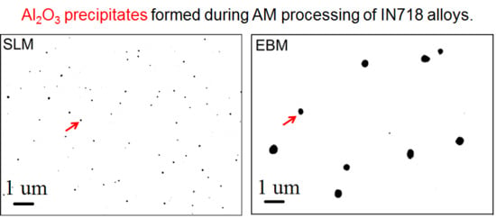
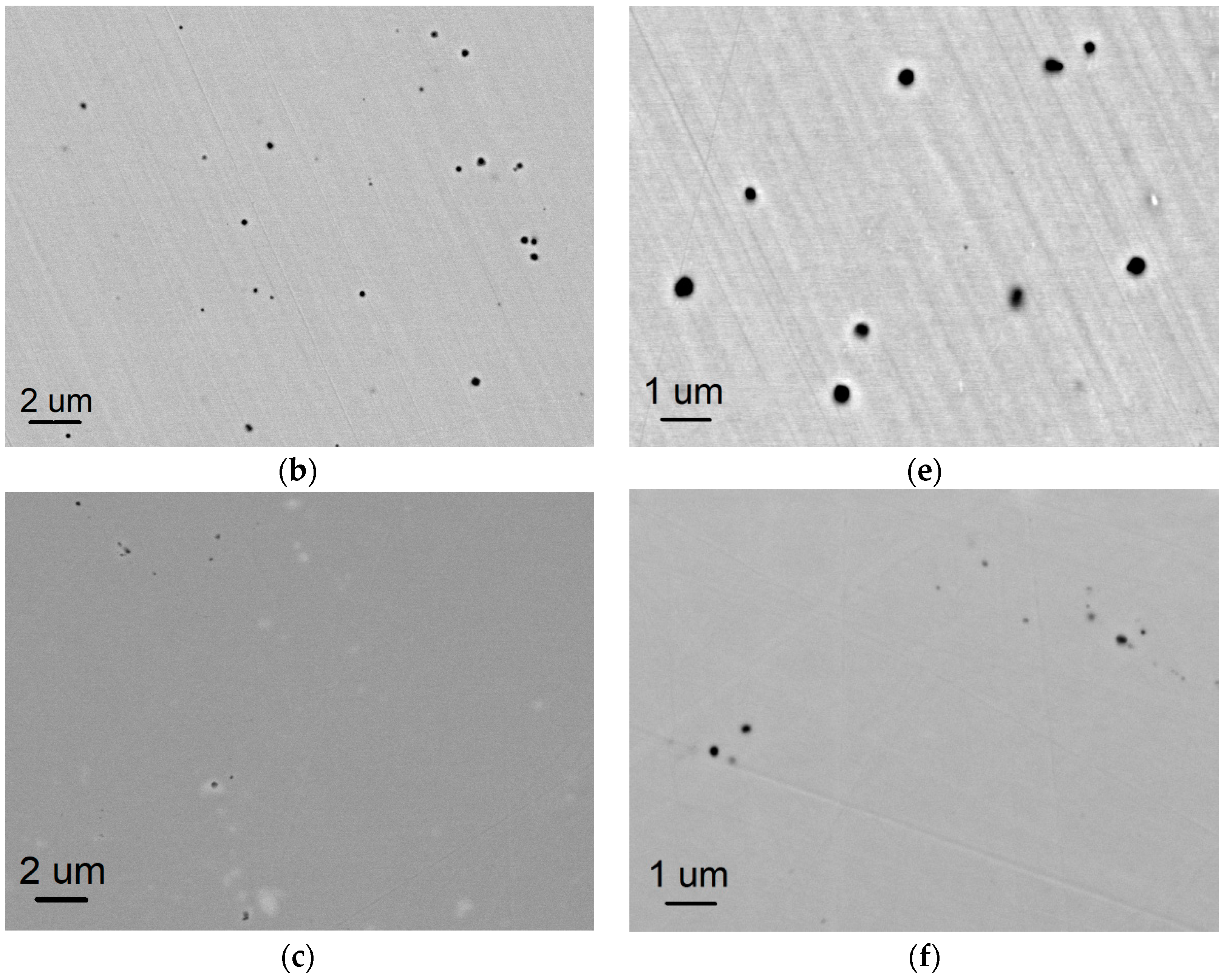
Figure 1 shows BSE images of AM-fabricated IN718 alloys, including (a) SLM, (b) EBM, and (c) SPS-fabricated substrates, in which correspondingly magnified images (d), (e), and (f) are shown, as well. Based on a different contrast in the BSE images, it is recognized that there are several black precipitates uniformly dispersed in each AM-fabricated sample, i.e., (d) a high number density and a small size of the particles in SLM-IN718 substrate, (e) several sparser black particles with a larger size are distributed in EBM-IN718 substrate. However, in contrast to the high precipitates volume fraction of AM-fabricated substrates, only a few precipitates could be found in the substrate consolidated by SPS (Figure 1c, f). The detailed area fraction of the black precipitates in each sample was calculated with ImageJ software, which is corresponded to 0.269% in SLM, 0.883% in EBM, and 0.133% in SPS alloys. In addition, there are large amounts of secondary phase with white contrast in the BSE image of SLM-processed IN718, marked with arrows in Figure 1d.
EPMA elemental maps of the SLM- and EBM-fabricated IN718 samples are exhibited in Figure 2. Figure 2a shows that the fine black particles in SLM-IN718 alloy are Al2O3 precipitates, due to an enrichment of aluminum and oxygen. Besides, the white phase marked by black arrow in Figure 2a is obviously rich in niobium and titanium. In the case of EBM-processed sample, in addition to aluminum and oxygen, the coarser black particles are demonstrated to be enriched with niobium and titanium simultaneously, as shown in Figure 2b.
A higher magnification observation on the dispersed particles was carried out with STEM, as shown in Figure 3a–e. Based on high-angle annual dark-field (HAADF) STEM and bright-field (BF) STEM imaging modes and corresponding EDS maps, the morphology and element compositions of each particle could be identified clearly. As shown in Figure 3a, due to the high image contrast of Al-including particles with dark color in the HAADF images, the Al2O3 particles in SLM-IN718 alloy with a spherical shape are easily distinguished, corresponding to the enrichment of Al and O in the elemental maps of Figure 3c. It is noticeable that one of the Al2O3 particles is covered with white region, and another one is free, as marked with light blue arrow and red arrow in the HAADF image of Figure 3c, respectively. The EDS maps show that the covered particle possesses an enrichment of Ti. Besides, the white phase could be also observed in Figure 3a, in which an orderly arrangement of the white phase in matrix could be confirmed from the HADDF image with low magnification. Based on corresponding EDS maps, a high Nb concentration was demonstrated in the white phase. With respect to EBM-IN718 alloy, in addition to a sparse number density (Figure 3b), a unique core-shell shape characteristic of the particle could be observed, based on the difference of image contrast in the HAADF image of Figure 3d, namely, a dark black area is located at center (noted by red arrow) and is wrapped by a light gray region (noted by light blue arrow). Based on corresponding EDS maps, it can be found that Al and O are relatively enriched at the dark black area, and Ti, Nb with strong signal of Ti are enriched at the light gray region. Additionally, the distribution of fine gray precipitates with high number density could be identified with BF image, as marked by a yellow arrow in Figure 3d. EDS maps in Figure 3e show that the fine gray precipitates possess high concentrations of Nb, Ti, and Ni.
In order to figure out the core-shell structure in more detail, a composition profile across the particle in EBM-fabricated IN718 substrate was carried out with EDS point analysis, as shown in Figure 4, suggesting that the atomic percentages of all components are approximate to Al2O3 in the core of the particle and Ti/Nb compositions at the periphery. Based on TEM observation, the mean size of Al2O3 precipitates were calculated to be 42.5 nm and 93.2 nm in SLM- and EBM-fabricated samples, respectively.
3.2. Oxidation Behavior of Raw Powders
Figure 5 shows the TEM characterization on cross-sections of the oxide scales formed on IN718 powders after the oxidation at 800 °C for 5 min in vacuum (<10−3 Pa) and in air, respectively. Figure 5a represents the result obtained from the oxidation in vacuum (<10−3 Pa), in which a very thin oxide scale formed on the powder surface could be confirmed. However, the scale is too thin to be identified with EDS equipped in STEM. After changing environment to air, the oxide scale grew to be considerably thick, as shown with TEM image in Figure 5b. Based on EDS point analysis, the outer layer of the oxide scale was identified to be (Ni, Fe) Cr2O4 spinel and the inner layer was Cr2O3. In addition, Nb/Al-enriched oxide region was found beneath the Cr2O3 layer. The detailed EDS analysis results of the scale formed in air are exhibited in Table 2.
3.3. Microstructures of SPS-Fabricated Alloys
In order to investigate the effect of powder surface oxides on the microstructures of consolidated alloys, the pre-oxidized powders were consolidated with SPS. Figure 6 shows the microstructures of IN718 alloy obtained from consolidating each kind of powder, including the powders without pre-oxidation (Figure 6a) and the ones that oxidized at 800 °C for 5 min in vacuum (Figure 6b) and in air (Figure 6c). In contrast to the few black secondary precipitates in the sample consolidated with non-oxidation powders, it can be clearly confirmed that the black precipitates are well developed along the powder boundaries in SPS-consolidated substrate using pre-oxidized powders. It is obvious that the volume fraction of these black particles increases significantly with the changing of environment from vacuum to air, as exhibited in Figure 6b,c. EPMA wavelength dispersive spectrometer (WDS) point analysis was utilized to quantitatively analyze the compositions of the black precipitates formed in SPS-fabricated bulk alloys. Figure 7a, b and Table 3 show the obtained results by using the powders oxidized at 800 °C for 5 min in vacuum and in air, respectively. In accordance with a relatively high concentration of Al and O in atomic percentages, the black particles were considered to be Al2O3.
4. Discussion
4.1. Microstructures of AM- and SPS-Fabricated Alloys
Based on the characterization of AM-fabricated Ni-based alloys, including SLM-processed and EBM-processed IN718 samples, it could be confirmed that residues uniformly disperse inside AM-fabricated substrates, and most of them are oxides. However, lesser residues were found in SPS-consolidated alloy than both SLM and EBM. The reason could be associated with a low oxygen potential in SPS processing than that in SLM/EBM. As shown with a Ni–O binary phase diagram in Figure 8, it is noticeable that the oxygen solubility in nickel increases significantly once temperature reaches to melting point of nickel, and higher oxygen solubility could be expected with the temperature increasing further [20,21].
It is widely known that SPS is a kind of solid-phase sintering performed at relatively low temperatures, and the oxygen content introduced into Ni matrix via the solid solution should be extremely limited. However, AM technologies are based on the melting of raw powders, which is a typical liquid-phase sintering, and more oxygen can be introduced with higher oxygen solubility in the liquid phase, as reflected in Figure 8. Moreover, in comparison with the direct exposure of raw powder in AM chamber, during SPS consolidation, the powders are covered with a pure Ni sheet, a carbon sheet, and a graphite mold, which could considerably reduce the oxygen potential in the powder surface of SPS.
In the case of the residues formed in AM technique, the morphology of the residues depends on AM processing methods. Residues in SLM processing are much different from the ones in EBM, i.e., the spherical Al2O3 precipitates with a small size and a large number density dominate the IN718 substrate processed with SLM, whereas the sparse precipitates with a coarse size disperse in EBM-fabricated sample. Besides, a unique core-shell structure with Al2O3 in a core and Ti/Nb composite at a periphery was found for the precipitates in EBM. In SLM processing, a laser beam with ultra-high energy irradiates metal powders and then melts the powders instantaneously in a small area. After making a micro melt pool, the beam will move to next positions with a high scanning speed, leading to a high cooling rate of 103 to 108 K/s, which is prone to inducing more rapid cooling and solidification of the original melt pool [1,11]. It was reported that such rapid melting/cooling rate results in an extremely high-volume fraction of liquid/solid interface and a significant refinement of grains [11]. Based on the mechanism that a new grain formation typically starts at the boundary of components where partially molten powder particles act as new nuclei [3], Al2O3 particles crystallized in the melt pool on cooling, and the crystallization rate of Al2O3 could be increased significantly in SLM processing with higher nucleation sites, corresponding to the high Al2O3 number density in Figure 1. On the other hand, with respect to EBM process, a larger beam diameter was utilized. The larger beam diameter in EBM usually results in a larger melt pool dimension than SLM. In addition to the larger melt pools, a quite slow cooling rate occurs in EBM. It is known that the pre-heat or pre-melt scan is necessary for EBM powder bed, thus, the powders have been already pre-heated to a certain temperature around 0.5–0.8 melting temperature (Tm), and the cooling rate of the melt pool would be decreased drastically after the departure of electron beam [2,4]. Consequently, a relatively slow solidification exists in EBM and fewer sites appear for new nucleation of Al2O3. Besides, due to the long processing times and high temperatures with slower cooling, the original solid parts would suffer from an in situ heat treatment during the subsequent EBM fabrication of recoated powders, and this process has been claimed to be responsible for the growth of precipitates [22] and was supposed to contribute the coarsening of the residues in EBM. Even after the overall building process, a considerably long cooling time, such as overnight, is needed, since a high temperature still remains in the entire EBM chamber, which may further promote the coarsening of residues.
The unique core-shell structure of residues with Al2O3 in the core and Ti/Nb compositions at the periphery, suggesting that Ti/Nb phase was precipitated on the surface of Al2O3 particle and could easily be coarsened due to the high temperature during the process of EBM. Mostafa et al. [23,24] claimed that the white precipitates enriched with Nb and Ti in the homogenized SLM-printed IN718 alloy are MC-type carbides, which also exists in the printed specimens, but cannot be detectable because of their fine size. Thus, it is reasonable to consider that the pre-formed Al2O3 particles in EBM-fabricated substrate act as a nucleation site for Ti/Nb carbides. Precipitates grew by a diffusion process with a slow cooling rate in EBM process, resembling the process of homogenization heat treatment [25]. Besides, a slight coating of the Ti/Nb carbides also could be found in Al2O3 particles of SLM, as proved with the one noted by the light blue arrow in Figure 3c. The core-shell structure is not obvious in SLM, which is associated with the fast cooling rate. The formation processes of the residues in SLM- and EBM-fabricated IN718 substrates are summarized and exhibited schematically in Figure 9.
With respect to the fine gray precipitates exhibited in BF images of Figure 3d,e, they should be δ and/or γ″ phases, due to the enrichment of Nb, Ti, and Ni, which are derived from the available precipitation in the high temperature process of EBM fabrication [26]. On the other hand, the white Nb-enriched phases in SLM IN718 alloy are considered to be γ″ phase. Mostafa et al. [23] investigated the Nb-rich regions in the interdendritic spaces of SLM-built specimen, and reported those are γ″ phase (bct-Ni3Nb) using semi-quantitative EDS analysis and XRD refinement. Besides, it was claimed that the γ″ precipitates formed in a columnar microstructural architecture and are parallel to γ matrix, which are consistent with the orderly arrangement of the Nb-enriched white precipitates in Figure 3a. δ phase is difficult to form in SLM-printed IN718 alloy because of the high cooling rate during SLM fabrication [23,27,28,29,30,31].
4.2. Calculation of the Introduced Oxygen Content in AM Process
Based on the oxidation behavior of raw IN718 powder, it has been demonstrated that Ni-included spinel and Cr2O3 layers are the main oxidation product at 800 °C in air for 5 min. After SPS consolidation, Cr2O3 and spinel completely disappeared, and new oxides of Al2O3 precipitates existed along the powder boundaries in the substrate. For SPSed samples, the amount of the oxides in the substrate increases from vacuum to air, consistent with the thickness increase of the oxide scales formed on raw powders, as shown with the TEM images in Figure 5. The amount of the oxides in substrate was increased with the thickness of the oxide scales formed on raw powders, resulting from a higher oxygen content introduced through powders. The original powder surface oxides, such as spinel and Cr2O3, were decomposed during SPS. The oxygen released from the oxide scale reacted with Al to form more stable oxides in the substrate, namely, Al2O3 particles in IN718 alloy. This is because Cr2O3 possesses lower oxygen affinity than that of Al2O3, as reflected by Ellingham diagram in Figure 10 [32,33].
With respect to the AM process, it can be readily understood that no matter what kinds of oxide contaminations formed on raw powder surface, they must be transformed to the most stable oxide, Al2O3, in AM-fabricated substrate, at such high operating temperatures of AM. In order to calculate the introduced oxygen content during AM process, the results of SPSed samples that came from the pre-oxidized powders are utilized. As described in the above section, the powders for SPS went through pre-oxidation, in which the introduced oxygen content can be assessed through analyzing the oxide scale formed on the powder surface. As shown in Figure 5, TEM characterization proved that the oxide scale that formed on the raw powders pre-oxidized at 800 °C for 5 min in air possesses a scale thickness of almost 90 nm, i.e., an external (Ni, Fe) Cr2O4 layer with 50 nm and an inner Cr2O3 layer with 40 nm. The mean diameter of the raw powders is deemed to be 60 μm, and then the introduced oxygen content for one powder after pre-oxidation at 800 °C for 5 min in air could be calculated to be 0.202 wt%, which is approximately equal to the value contained in SPS-consolidated sample. In this study, the introduced oxygen, regardless of whether in SPS via pre-oxidizing powders or that in AM by contamination during AM process, is supposed to completely transform into Al2O3 precipitates in substrate. Since it has been certified that all the residual oxides in the substrate of SPS- and AM-fabricated samples are Al2O3, the introduced oxygen content in AM process can be assessed by comparing the volume fraction of Al2O3 in SPS-fabricated samples. Figure 11 exhibited the area fraction of Al2O3 precipitates formed in all AM- (SLM and EBM) and SPS-(using pre-oxidized powders at 800 °C for 5 min in vacuum and in air) samples, in which the value of area fraction was calculated with ImageJ software by analyzing corresponding SEM images. Thus, the introduced oxygen content in SLM and EBM processes can be calculated to be 0.030 wt% and 0.099 wt%, respectively. The oxygen content is much higher than the original content in raw powders, for the case of SLM (0.019 wt%) or that in EBM (0.014 wt%), suggesting that a considerable amount of oxygen was introduced during AM process, and leads to the formation of new oxides during cooling process.
5. Conclusions
Residual oxides dominated by Al2O3 and a unique core-shell complex composites with Al2O3 in the center, and Ti/Nb at the periphery, were confirmed to exist in IN718 alloy fabricated by additive manufacturing (AM). The morphology of these residues depends on the utilized processing of SLM or EBM. In the case of AM process, oxygen would be introduced in the melt and Al2O3 crystallized during the cooling process, and a different cooling rate in SLM and EBM results in a different distribution of Al2O3 precipitates. In both SLM and EBM processes, Nb/Ti carbides precipitate during the process at a high temperature with Al2O3 as a nucleation site during the solidification. In the case of EBM process, the carbide has a unique core-shell structure. Precipitation of γ″/δ phases, however, has no relationship with Al2O3 precipitates. The size and distribution of the Al2O3 precipitates may be altered according to practical processing parameters in AM, which need further investigation. In order to investigate the evolution of these oxides from powders to consolidated alloys, the pre-oxidized IN718 raw powders at 800 °C for 5 min in vacuum and in air were consolidated with SPS. Oxidation behavior of the raw powders oxidized in air for 5 min proved that Ni-included spinel and Cr2O3 are the main oxidation products. After SPS consolidation, residual oxides were found to disperse along powder boundaries in the substrate of SPS-consolidated alloys, as an Al2O3, due to the high stability of the oxide in IN718 alloy substrate. According to the comparison between the content of Al2O3 precipitates formed in SPS- and AM-fabricated samples, the oxygen contents in substrates during SLM and EBM process were found to increase by 0.030 wt% and 0.099 wt%, respectively.
Author Contributions
S.H. conceived and designed the experiments; H.Y. performed the experiments and analyzed the data; K.K. and Y.-L.K. fabricated the bulk alloys by SLM and EBM; H.Y. and S.H. wrote the paper; K.K. and Y.-L.K. revised the paper. The research project was supervised by K.K. and S.H.
Acknowledgments
This work is supported by the ALCA program of the Japan Science and Technology Agency, JST. This work was conducted at “Joint-use Facilities: Laboratory of Nano-Micro Material Analysis”, Hokkaido University, supported by “Nanotechnology Platform” Program of the Ministry of Education, Culture, Sports, Science and Technology (MEXT), Japan.
Conflicts of Interest
The authors declare no conflict of interest.
References
- Gu, D.D.; Meiners, W.; Wissenbach, K.; Poprawe, R. Laser additive manufacturing of metallic components: Materials, processes and mechanisms. Int. Mater. Rev. 2012, 57, 133–164. [Google Scholar] [CrossRef]
- Korner, C. Additive manufacturing of metallic components by selective electron beam melting-a review. Int. Mater. Rev. 2016, 61, 361–377. [Google Scholar] [CrossRef]
- Murr, L.E.; Martinez, E.; Amato, K.N.; Gaytan, S.M.; Hernandez, J.; Ramirez, D.A.; Shindo, P.W.; Medina, F.; Wicker, R.B. Fabrication of metal and alloy components by additive manufacturing: Examples of 3D materials science. J. Mater. Res. Technol. 2012, 1, 42–54. [Google Scholar] [CrossRef]
- Gokuldoss, P.K.; Kolla, S.; Eckert, J. Additive manufacturing processes: Selective laser melting, electron beam melting and binder jetting-selection guidelines. Materials 2017, 10, 672. [Google Scholar] [CrossRef] [PubMed]
- Jia, Q.B.; Gu, D.D. Selective laser melting additive manufacturing of Inconel 718 superalloy parts: Densification, microstructure and properties. J. Alloys Compd. 2014, 585, 713–721. [Google Scholar] [CrossRef]
- Kuo, Y.L.; Kakehi, K. Influence of powder surface contamination in the Ni-based superalloy alloy718 fabricated by selective laser melting and hot isostatic pressing. Metals 2017, 7, 367. [Google Scholar] [CrossRef]
- Bai, Q.; Lin, J.; Jiang, J.; Dean, T.A.; Zou, J.; Tian, G. A study of direct forging process for powder superalloys. Mater. Sci. Eng. A 2015, 621, 68–75. [Google Scholar] [CrossRef]
- Rao, G.A.; Srinivas, M.; Sarma, D.S. Effect of solution treatment temperature on microstructure and mechanical properties of hot isostatically pressed superalloy Inconel 718. Mater. Sci. Technol. 2004, 20, 1161–1170. [Google Scholar] [CrossRef]
- Vilaro, T.; Colin, C.; Bartout, J.D.; Naze, L.; Sennour, M. Microstructural and mechanical approaches of the selective laser melting process applied to a nickel-based superalloy. Mater. Sci. Eng. A 2012, 534, 446–451. [Google Scholar] [CrossRef]
- Tucho, W.M.; Cuvillier, P.; Kverneland, A.S.; Hansen, V. Microstructure and hardness studies of Inconel 718 manufactured by selective laser melting before and after solution heat treatment. Mater. Sci. Eng. A 2017, 689, 220–232. [Google Scholar] [CrossRef]
- Song, B.; Zhao, X.; Li, S.; Han, C.J.; Wei, Q.S.; Wen, S.F.; Liu, J.; Shi, Y.S. Different in microstructure and properties between selective laser melting and traditional manufacturing for fabrication of metal parts: A review. Front. Mech. Eng. 2015, 10, 111–125. [Google Scholar] [CrossRef]
- Trosch, T.; Strobner, J.; Volkl, R.; Glatzel, U. Microstructure and mechanical properties of selective laser melted Inconel 718 compared to forging and casting. Mater. Lett. 2016, 164, 428–431. [Google Scholar] [CrossRef]
- Amato, K.N.; Gaytan, S.M.; Murr, L.E.; Martinez, E.; Shindo, P.W.; Hernandez, J.; Collins, S.; Medina, F. Microstructures and mechanical behavior of Inconel 718fabricated by selective laser melting. Acta Mater. 2012, 60, 2229–2239. [Google Scholar] [CrossRef]
- Wang, X.Q.; Keya, T.; Chou, K. Build height effect on the Inconel 718 parts fabricated by selective laser melting. Procedia Manuf. 2016, 5, 1006–1017. [Google Scholar] [CrossRef]
- Korner, C.; Helmer, H.; Bauereib, A.; Singer, R.F. Tailoring the grain structure of IN718 during selective electron beam melting. In Proceedings of the Eurosuperalloys 2014, MATEC Web of Conferences, Giens, France, 12–16 May 2014; Volume 14. Article number 08001. [Google Scholar]
- Jia, Q.B.; Gu, D.D. Selective laser melting additive manufactured Inconel 718 superalloy parts: High-temperature oxidation property and its mechanisms. Opt. Laser Technol. 2014, 62, 161–171. [Google Scholar] [CrossRef]
- Wang, Z.M.; Guan, K.; Gao, M.; Li, X.Y.; Chen, X.F.; Zeng, X.Y. The microstructure and mechanical properties of deposited IN718 by selective laser melting. J. Alloys Compd. 2012, 513, 518–523. [Google Scholar] [CrossRef]
- Zhang, Y.N.; Cao, X.; Wanjara, P.; Medraj, M. Oxide films in laser additive manufactured Inconel 718. Acta Mater. 2013, 61, 6562–6576. [Google Scholar] [CrossRef]
- Ardila, L.C.; Garciandia, F.; Gonzalez-Diaz, J.B.; Alvarez, P.; Echeverria, A.; Petite, M.M.; Deffley, R.; Ochoa, J. Effect of IN718 recycled powder reuse on properties of parts manufactured by means of selective laser melting. Phys. Procedia 2014, 56, 99–107. [Google Scholar] [CrossRef]
- Kowalski, M.; Spencer, P.J. Thermodynamic reevaluation of the C-O, Fe-O and Ni-O systems: Remodelling of the liquid, BCC and FCC phases. Calphad 1995, 19, 229–243. [Google Scholar] [CrossRef]
- Perusin, S.; Monceau, D.; Andrieu, E. Investigations on the diffusion of oxygen in nickel at 1000 °C by SIMS analysis. J. Electrochem. Soc. 2005, 152, 390–397. [Google Scholar] [CrossRef]
- Sames, W.J.; Unocic, K.A.; Dehoff, R.R.; Lolla, T.; Babu, S.S. Thermal effects on microstructural heterogeneity of Inconel 718 materials fabricated by electron beam melting. J. Mater. Res. 2014, 29, 1920–1930. [Google Scholar] [CrossRef]
- Mostafa, A.; Rubio, I.P.; Brailovski, V.; Jahazi, M.; Medraj, M. Structure, texture and phases in 3D printed IN718 alloy subjected to homogenization and HIP treatments. Metals 2017, 7, 196. [Google Scholar] [CrossRef]
- Parimi, L.L.; Ravi, G.A.; Clark, D.; Attallah, M.M. Microstructure and texture development in direct laser fabricated IN718. Mater. Charact. 2014, 89, 102–111. [Google Scholar] [CrossRef]
- Benn, R.C.; Salva, R.P. Additive manufactured Inconel alloy 718. In Proceedings of the 7th International Syposium on Superalloy 718 and Derivatives, TMS, Pittsburgh, PA, USA, 10–13 October 2010; pp. 455–469. [Google Scholar]
- Rao, G.A.; Srinivas, M.; Sarma, D.S. Influence of modified processing on structure and properties of hot isostatically pressed superalloy Inconel 718. Mater. Sci. Eng. A 2006, 418, 282–291. [Google Scholar] [CrossRef]
- Xie, X.S.; Xu, C.M.; Wang, G.L.; Dong, J.X.; Cao, W.D.; Kennedy, R. TTT diagram of a newly developed nickel-based superalloy-Allvac 718plusTM. In Proceedings of the Superalloys 718, 625, 706 and Derivatives 2005, TMS, Pittsburgh, PA, USA, 2–5 October 2005; pp. 193–202. [Google Scholar]
- Srinivasan, D.; Lawless, L.U.; Ott, E.A. Experimental determination of TTT diagram for alloy 718plus. In Proceedings of the Superalloys 2012: 12th International Symposium on Superalloys, TMS, Seven Springs, PA, USA, 9–13 September 2012; pp. 759–768. [Google Scholar]
- Azadian, S.; Wei, L.Y.; Warren, R. Delta phase precipitation in Inconel 718. Mater. Charact. 2004, 53, 7–16. [Google Scholar] [CrossRef]
- Dehmas, M.; Lacaze, J.; Niang, A.; Viguier, B. TEM study of high-temperature precipitation of Delta phase in Inconel 718. Adv. Mater. Sci. Eng. 2011, 2011, 1–9. [Google Scholar] [CrossRef]
- Liu, Y.C.; Guo, Q.Y.; Li, C.; Mei, Y.P.; Zou, X.S.; Huang, Y.; Li, H.J. Recent progress on evolution of precipitates on Inconel 718 superalloy. Acta Metall. Sin. 2016, 52, 1259–1266. [Google Scholar]
- He, Y.D.; Li, Z.W.; Qi, H.B.; Gao, W. Standard free energy change of formation per unit volume: A new parameter for evaluating nucleation and growth of oxides, sulphides, carbides and nitrides. Mater. Res. Innov. 1997, 1, 157–160. [Google Scholar] [CrossRef]
- Stratton, P. Ellingham diagrams-their use and misuse. IHTSE 2013, 7, 70–73. [Google Scholar] [CrossRef]
Figure 1.
BSE images obtained from the AM- and SPS-fabricated substrates, (a,b) represent the IN718 samples processed by SLM and EBM, respectively, (c) is SPS-consolidated IN718 alloy. (d–f) are correspondingly magnified BSE images.
Figure 1.
BSE images obtained from the AM- and SPS-fabricated substrates, (a,b) represent the IN718 samples processed by SLM and EBM, respectively, (c) is SPS-consolidated IN718 alloy. (d–f) are correspondingly magnified BSE images.
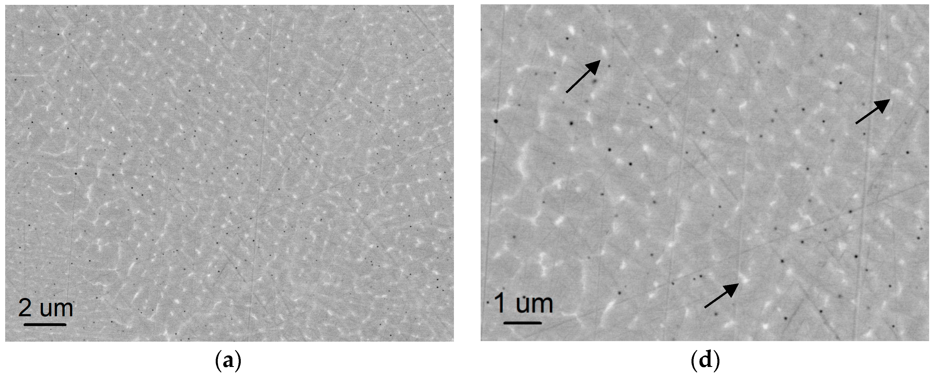

Figure 2.
EPMA elemental mappings obtained from (a) SLM-fabricated and (b) EBM-fabricated IN718 bulk alloys.
Figure 2.
EPMA elemental mappings obtained from (a) SLM-fabricated and (b) EBM-fabricated IN718 bulk alloys.
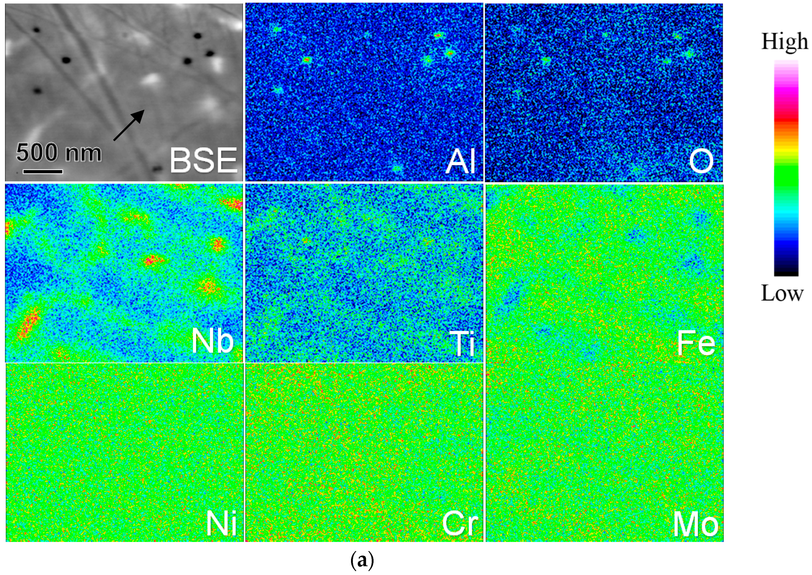
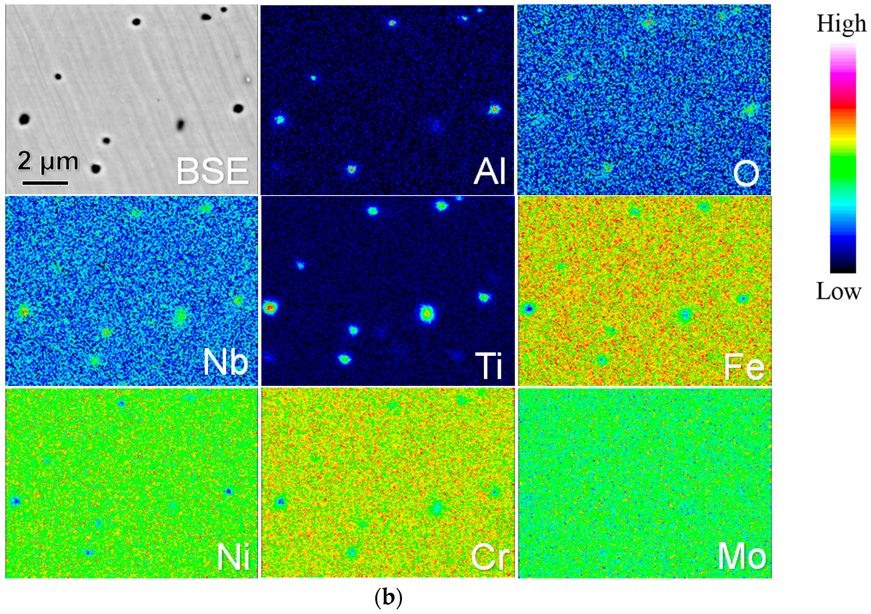
Figure 3.
HAADF-STEM images of residues in the AM-fabricated IN718 samples and corresponding EDS elemental maps of Al, O, Cr, Nb, Ti, Ni, Fe, Mo, in which (a,c) belong to SLM-fabricated sample and (b,d,e) belong to EBM-processed sample.
Figure 3.
HAADF-STEM images of residues in the AM-fabricated IN718 samples and corresponding EDS elemental maps of Al, O, Cr, Nb, Ti, Ni, Fe, Mo, in which (a,c) belong to SLM-fabricated sample and (b,d,e) belong to EBM-processed sample.
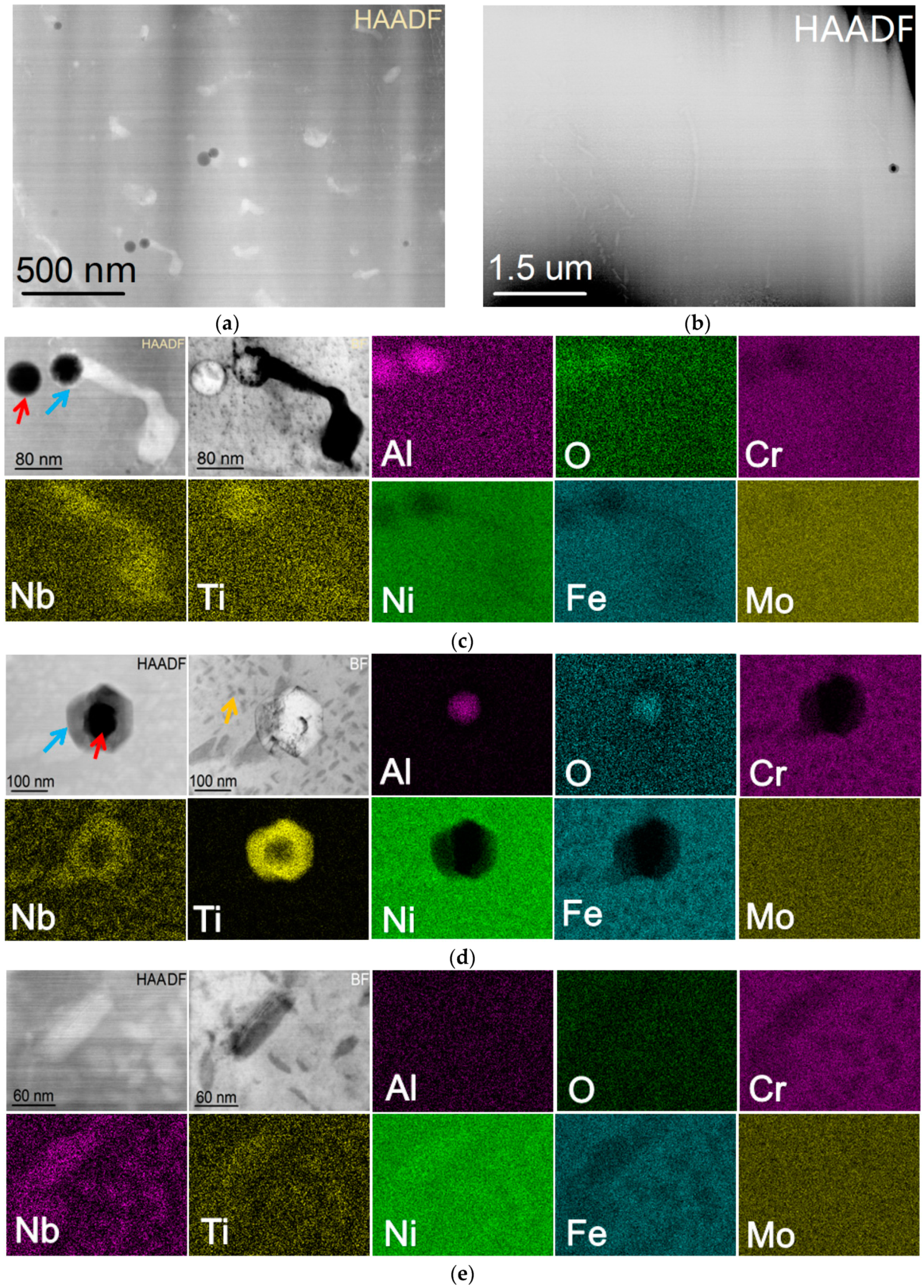
Figure 4.
The STEM EDS point analysis on the residue of the EBM-fabricated IN718 sample.
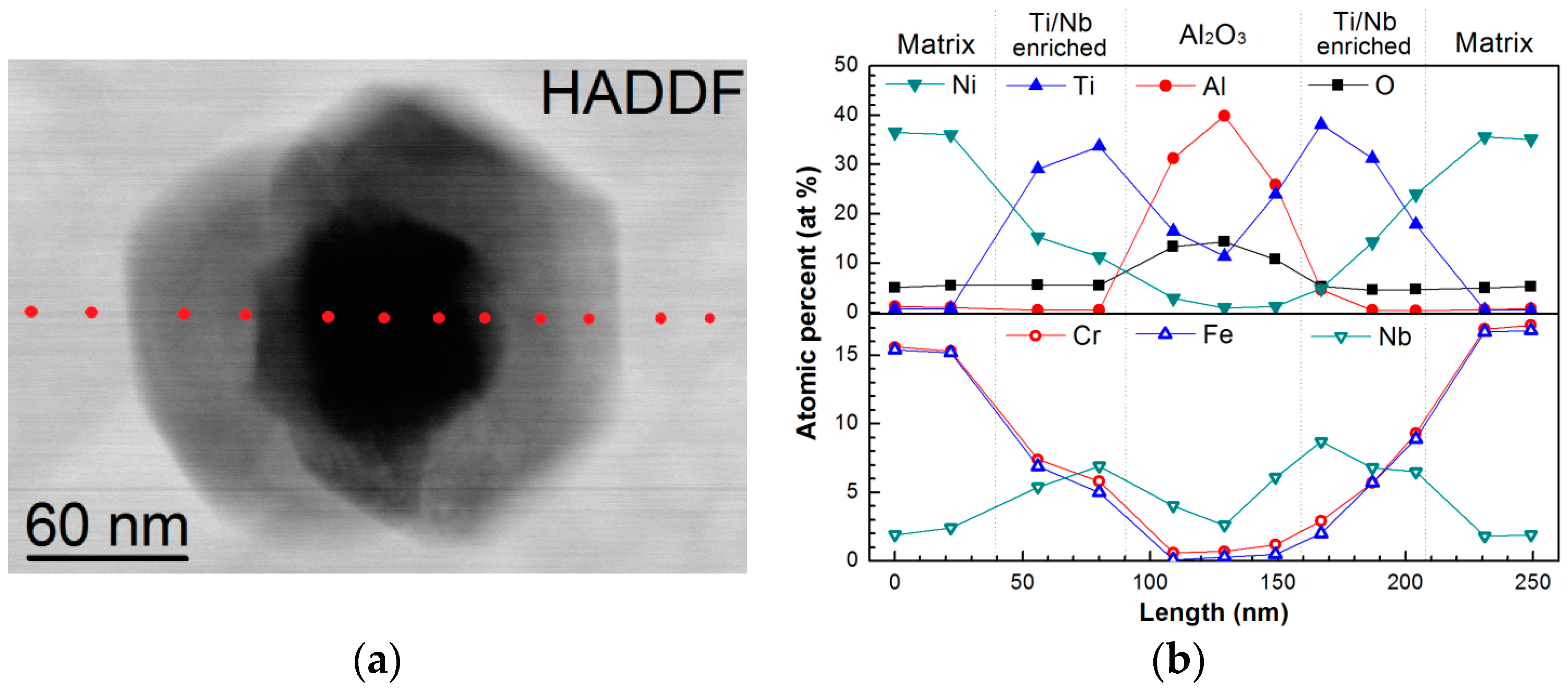
Figure 5.
The TEM images of the oxide scales formed on IN718 raw powders after oxidation on 800 °C for 5 min in vacuum (<10−3 Pa) (a) and in air (b).
Figure 5.
The TEM images of the oxide scales formed on IN718 raw powders after oxidation on 800 °C for 5 min in vacuum (<10−3 Pa) (a) and in air (b).

Figure 6.
BSE images of the SPS-consolidated IN718 bulk alloys, in which (a) represents the result obtained from the consolidation of non-oxidized powders, (b,c) are from the pre-oxidized powders at 800 °C for 5 min in vacuum and in air, respectively.
Figure 6.
BSE images of the SPS-consolidated IN718 bulk alloys, in which (a) represents the result obtained from the consolidation of non-oxidized powders, (b,c) are from the pre-oxidized powders at 800 °C for 5 min in vacuum and in air, respectively.

Figure 7.
BSE images of the residues formed in IN718 alloys consolidated by SPS with the pre-oxidized powders at 800 °C for 5 min in vacuum (a) and in air (b).
Figure 7.
BSE images of the residues formed in IN718 alloys consolidated by SPS with the pre-oxidized powders at 800 °C for 5 min in vacuum (a) and in air (b).
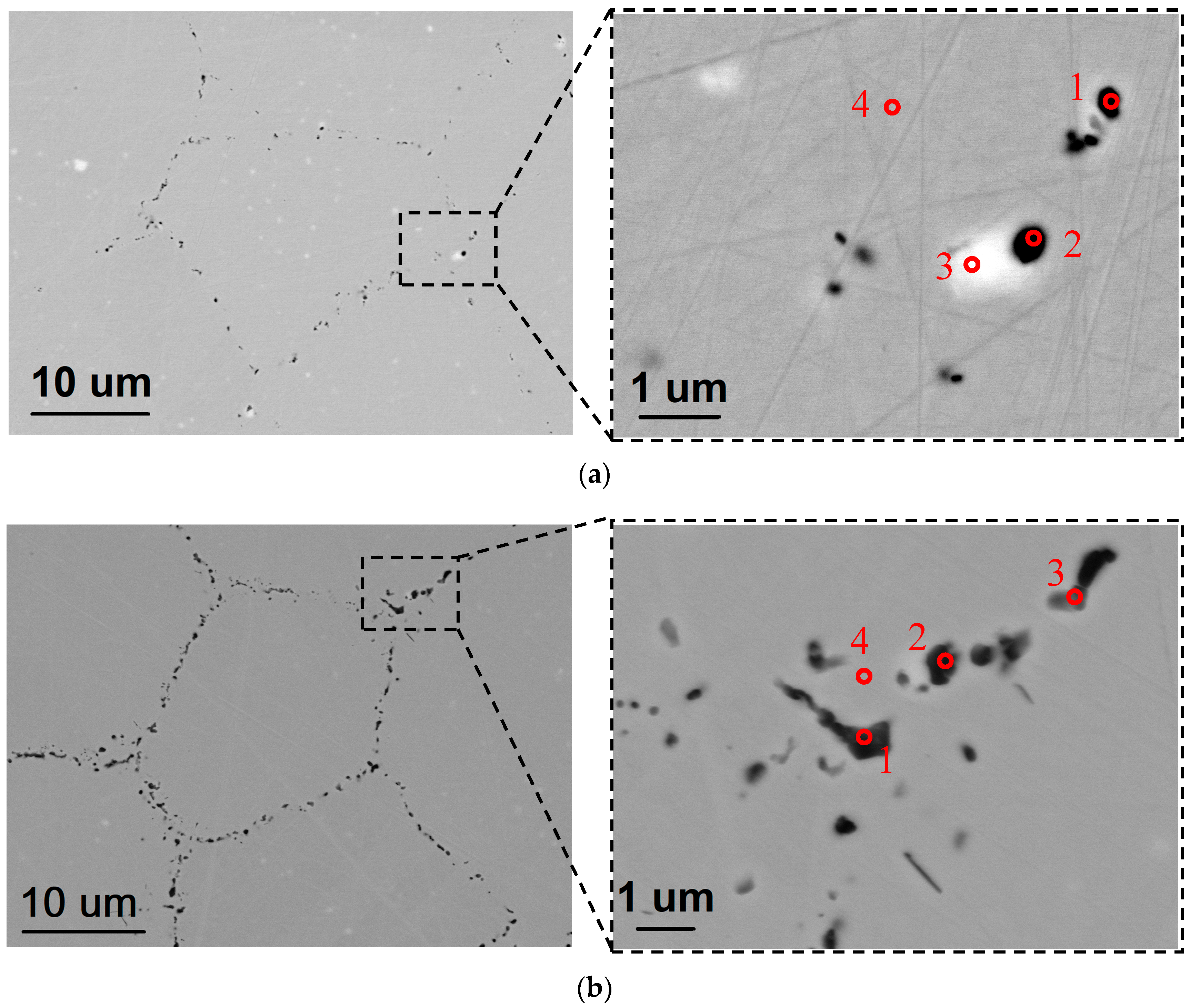
Figure 8.
Ni–O binary phase diagram shows oxygen solubility in nickel at high temperatures, in which the temperatures for SPS and SLM/EBM are marked, respectively.
Figure 8.
Ni–O binary phase diagram shows oxygen solubility in nickel at high temperatures, in which the temperatures for SPS and SLM/EBM are marked, respectively.
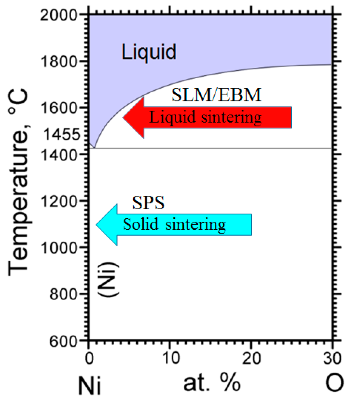
Figure 9.
Schematic illustrating the cooling process of IN718 alloy fabricated by SLM and EBM, respectively.
Figure 9.
Schematic illustrating the cooling process of IN718 alloy fabricated by SLM and EBM, respectively.
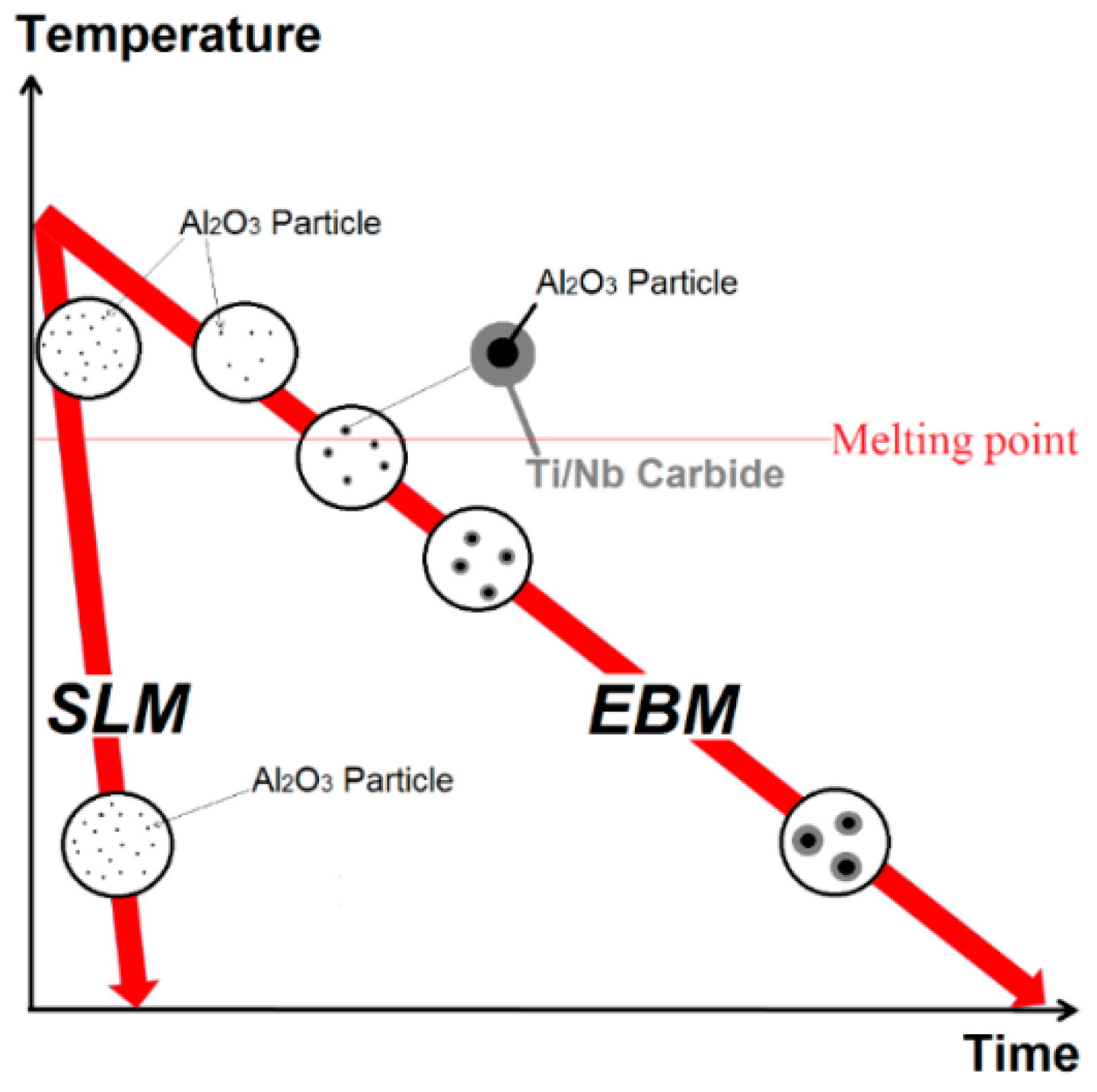
Figure 10.
Ellingham diagram, in which the related elements of Ni, Cr, Ti, and Al were marked.

Figure 11.
The content of Al2O3 precipitates formed in AM and SPS specimens, in which each value was calculated with ImageJ software.
Figure 11.
The content of Al2O3 precipitates formed in AM and SPS specimens, in which each value was calculated with ImageJ software.


Table 1.
Practical compositions of the raw powders used in this study (in mass%).
| Powders | Ni | Cr | Fe | Nb | Mo | Ti | Al | Co | O |
|---|---|---|---|---|---|---|---|---|---|
| IN718 SLM | Bal. | 19.63 | 18.21 | 5.05 | 2.85 | 1.10 | 0.46 | 0.03 | 0.019 |
| IN718 EBM | Bal. | 19.30 | 18.34 | 4.89 | 3.04 | 1.07 | 0.54 | 0.01 | 0.014 |
| IN718 SPS | Bal. | 18.92 | 18.09 | 5.21 | 3.02 | 0.90 | 0.62 | 0.02 | 0.016 |
Table 2.
Chemical composition of the scale formed on 800 °C for 5 min in air obtained from EDS point analysis (in atom %).
Table 2.
Chemical composition of the scale formed on 800 °C for 5 min in air obtained from EDS point analysis (in atom %).
| No. | Ni | Fe | Cr | Al | O | Mo | Nb | Ti |
|---|---|---|---|---|---|---|---|---|
| 1 | 9.2 | 9.2 | 6.1 | 0.1 | 72.5 | 2.7 | 0 | 0.2 |
| 2 | 7.7 | 9.5 | 6.6 | 0.2 | 73.5 | 2.2 | 0 | 0.1 |
| 3 | 0.1 | 0.2 | 19.9 | 0.9 | 74.8 | 2.0 | 1.5 | 0.5 |
| 4 | 0.7 | 0.8 | 25.0 | 0.6 | 69.6 | 2.2 | 0.7 | 0.6 |
| 5 | 9.9 | 2.9 | 6.4 | 2.3 | 67.9 | 3.4 | 5.3 | 1.9 |
| 6 | 48.8 | 11.8 | 9.0 | 0.4 | 20.5 | 7.2 | 1.9 | 0.5 |
| 7 | 44.0 | 11.0 | 6.2 | 1.0 | 27.7 | 7.3 | 2.4 | 0.5 |
| 8 | 38.7 | 12.8 | 15.0 | 1.2 | 23.7 | 6.4 | 1.7 | 0.4 |
Table 3.
Results of EPMA WDS point analysis obtained from the residues marked in Figure 7a, and b, respectively (in atom %).
Table 3.
Results of EPMA WDS point analysis obtained from the residues marked in Figure 7a, and b, respectively (in atom %).
| No. | Specimens | Cr | Nb | Ti | Ni | Al | O | Fe | Mo |
|---|---|---|---|---|---|---|---|---|---|
| 1 | Vacuum | 22.2 | 3.3 | 1.1 | 40.0 | 3.9 | 3.0 | 19.9 | 1.9 |
| 2 | 17.0 | 11.2 | 3.6 | 25.4 | 10.5 | 18.8 | 12.0 | 1.5 | |
| 3 | 17.5 | 28.3 | 7.5 | 30.7 | 1.2 | 0 | 13.5 | 1.4 | |
| 4 | 21.6 | 3.1 | 1.2 | 47.3 | 1.4 | 0 | 19.3 | 2.0 | |
| 1 | Air | 7.6 | 1.2 | 1.0 | 9.6 | 29.1 | 44.6 | 6.0 | 0.5 |
| 2 | 8.0 | 2.4 | 0.9 | 8.3 | 26.6 | 46.4 | 6.7 | 0.6 | |
| 3 | 14.5 | 1.6 | 0.8 | 30.1 | 12.2 | 26.3 | 12.5 | 1.1 | |
| 4 | 21.8 | 2.5 | 1.0 | 52.1 | 0.7 | 0 | 18.5 | 1.6 |
© 2018 by the authors. Licensee MDPI, Basel, Switzerland. This article is an open access article distributed under the terms and conditions of the Creative Commons Attribution (CC BY) license (http://creativecommons.org/licenses/by/4.0/).
Share and Cite
MDPI and ACS Style
Yu, H.; Hayashi, S.; Kakehi, K.; Kuo, Y.-L. Study of Formed Oxides in IN718 Alloy during the Fabrication by Selective Laser Melting and Electron Beam Melting. Metals 2019, 9, 19. https://doi.org/10.3390/met9010019
AMA Style
Yu H, Hayashi S, Kakehi K, Kuo Y-L. Study of Formed Oxides in IN718 Alloy during the Fabrication by Selective Laser Melting and Electron Beam Melting. Metals. 2019; 9(1):19. https://doi.org/10.3390/met9010019
Chicago/Turabian StyleYu, Hao, Shigenari Hayashi, Koji Kakehi, and Yen-Ling Kuo. 2019. "Study of Formed Oxides in IN718 Alloy during the Fabrication by Selective Laser Melting and Electron Beam Melting" Metals 9, no. 1: 19. https://doi.org/10.3390/met9010019
Note that from the first issue of 2016, this journal uses article numbers instead of page numbers. See further details here.