Article

Experimental Study on Cross Wedge Rolling of 21-4N Heat Resistant Steel

School of Mechanical Engineering, University of Science and Technology Beijing, Beijing 100083, China
Metals 2019, 9(1), 39; https://doi.org/10.3390/met9010039
Submission received: 20 December 2018 / Revised: 29 December 2018 / Accepted: 1 January 2019 / Published: 4 January 2019

Abstract

:
21-4N is a typical heat resistant steel used as the material of exhaust valves. The application of cross wedge rolling to manufacture preform for valves has the advantages of higher efficiency and better quality. In this study, cross wedge rolling of 21-4N with an area reduction ratio of 65% was experimentally studied. Twelve groups of different tool parameters of cross wedge rolling tests were carried out. It is found that a larger stretching angle or a smaller forming angle is better for surface quality. When the stretching angle is 7° and the forming angle is less than 25°, a smooth surface can be obtained. Furthermore, the influence of stretching angle on central quality is not obvious, but a greater forming angle is prone to get a better central quality. When the forming angle is larger than 30°, no central damage was found in the workpieces. Considering the balance of surface quality and central quality, a stretching angle of 7° and a forming angle of 30° is a suitable combination for cross wedge rolling of 21-4N with an area reduction ratio of 65%.

1. Introduction

The valve is one of the key parts used in diesel engines. It works under a corrosive environment with high temperatures and high pressure. Usually, austenitic alloy and superalloys are used for exhaust valves [1]. 21-4N is a typical heat resistant steel used as a material for exhaust valves in the automobile industry. It has good properties of tensile strength, yield strength, wear resistance and corrosion resistance. Traditionally, valves are formed by electric upsetting and forging. In this process, electric upsetting is used to manufacture the preform for forging. But some defects can easily occur during electric upsetting such as coarse grain, overheating, overlap and cracking [2,3]. In recent years, a team in the University of Science and Technology Beijing (USTB) proposed a new method to produce the preform of valves by cross wedge rolling (CWR), which has higher production efficiency and better control of product quality [4,5,6].
Cross wedge rolling is an advanced metal forming technology, which has many merits, such as high productivity, high forming precision and good quality [7]. Pater introduced an optimization method for the designing of the tools to be used in the cross wedge rolling process [8]. Li and Lovell established a failure criterion in cross wedge rolling [9] and presented several industrial examples to demonstrate the feasibility and efficiency of the CWR process [10]. Wang et al. established a simulation model for two-roll cross wedge rolling by using the three-dimensional rigid-plastic finite element method [11]. Pater used the CWR process to produce toothed shafts, eccentric step and ball studs [12,13,14], respectively. Peng studied the 42CrMo/Q235 laminated shaft forming by CWR and analyzed the interface properties [15,16,17]. Metin experimentally and numerically studied the deformation and failure of cross wedge rolling of a Ti6Al4V alloy [18]. Li et al. researched the effects of cross wedge rolling parameters on the formability of a Ti-6Al-4V alloy [19]. Shu investigated the closure laws of void in the core of a cross wedge rolling shaft and studied a close-open cross wedge rolling process [20,21,22]. Yang et al. studied the micro-mechanism of central damage formation during cross wedge rolling [23]. These published studies of CWR mostly focus on low alloy steel and light alloy. Usually, austenitic steel has poor plasticity. Egea et al. [24,25] introduced electropulses to enhance the formability of 308L with wires drawn, and studied the mechanical and metallurgical changes during the process. Zheng et al. [26] studied the high temperature compression behavior of 21-4N valve steel in hot working process. In this paper, cross wedge rolling of heat resistant alloy 21-4N was experimentally studied, and the effects of the stretching angle and forming angle on forming quality were discussed.

2. Design of CWR Process

A CWR process is illustrated in Figure 1, which consists of three zones: a knifing zone, stretching zone, and sizing zone. The basic parameters of CWR are forming angle α, stretching angle β, area reduction ratio ψ and the rolling temperature. Usually, the area reduction ratio ψ is fixed by the product and the rolling temperature is decided by the material properties. Therefore, the proper forming angle and stretching angle are needed be chosen to guarantee the forming quality of the product.
In the CWR process, billet rotates under the effect of wedge type rollers. At the same time, the billet is compressed in the radial direction and stretched in the axial direction. As such, the choose of forming angle and stretch angle should firstly meet the rotation condition [27]:
tan α tan β m d μ 2 π d k ( 1 + d D )
where m is the number of rollers, D is the roller’s diameter, d is the billet’s diameter, dk is the rotation diameter, and μ is the friction coefficient.
In the industrial practice, the forming angle is usually chosen in the range of 18–34°, and the stretching angle is chosen between 4 and 12°. In this study, a 21-4N bar with a diameter of 25 mm was rolled to form a single step with a diameter of 14.8 mm and length of 90 mm. The area reduction ratio of the step is 65%. A full permutation of forming angle (20°, 25°, 30°, 35°) and stretching angle (3°, 5°, 7°) was arranged to investigate the forming possibility of 21-4N by CWR.

3. Experiments and Results

3.1. Experiments Conditions

The rolling experiments were carried out using a H500 mill (USTB, Beijing, China) at the University of Science and Technology Beijing, China, as shown in Figure 2. The main technical parameters of the H500 mill are listed in Table 1. The raw material 21-4N was supplied by Bao Steel, Shanghai, China. The chemical composition of the 21-4N is listed in Table 2, and the tensile strength of 21-4N is listed in Table 3.

3.2. Experiment Results

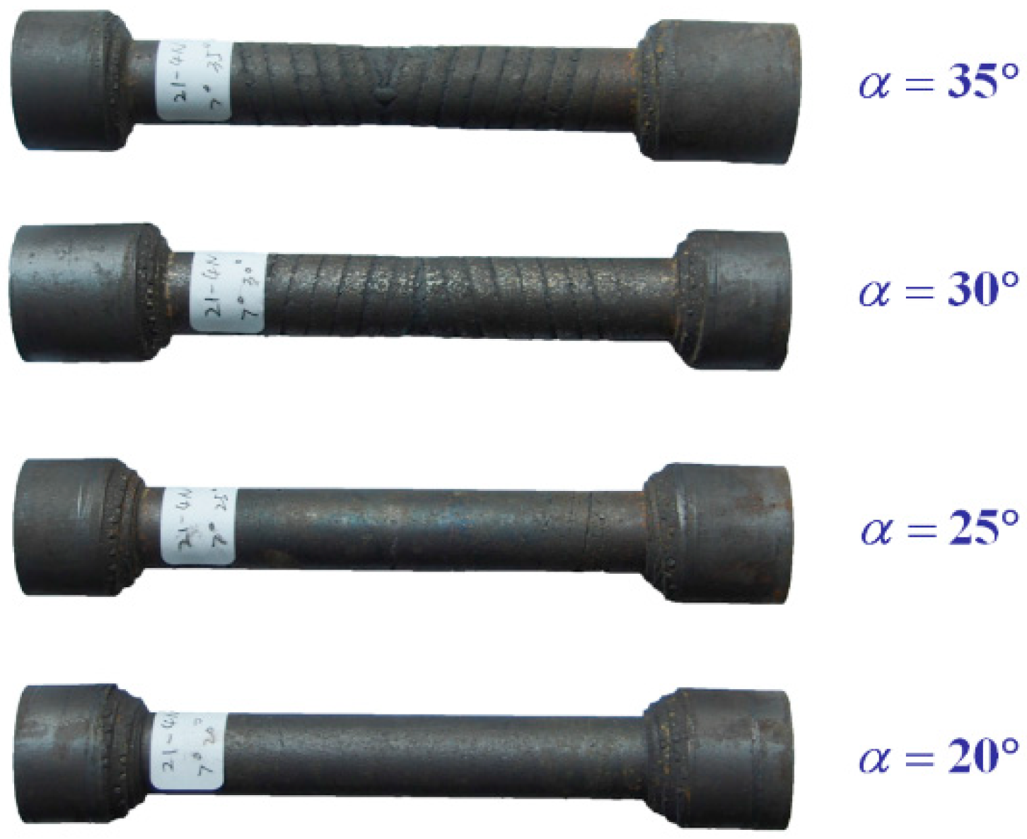
In the study, the 21-4N billet is firstly heated to 1100 °C in an electric tube furnace, and then immediately transferred to the H500 mill for rolling. Surface quality and central quality are checked and the results at various roller parameters are listed in Table 4. Some acquired parts are presented in Figure 3.

4. Discussion

4.1. Surface Quality

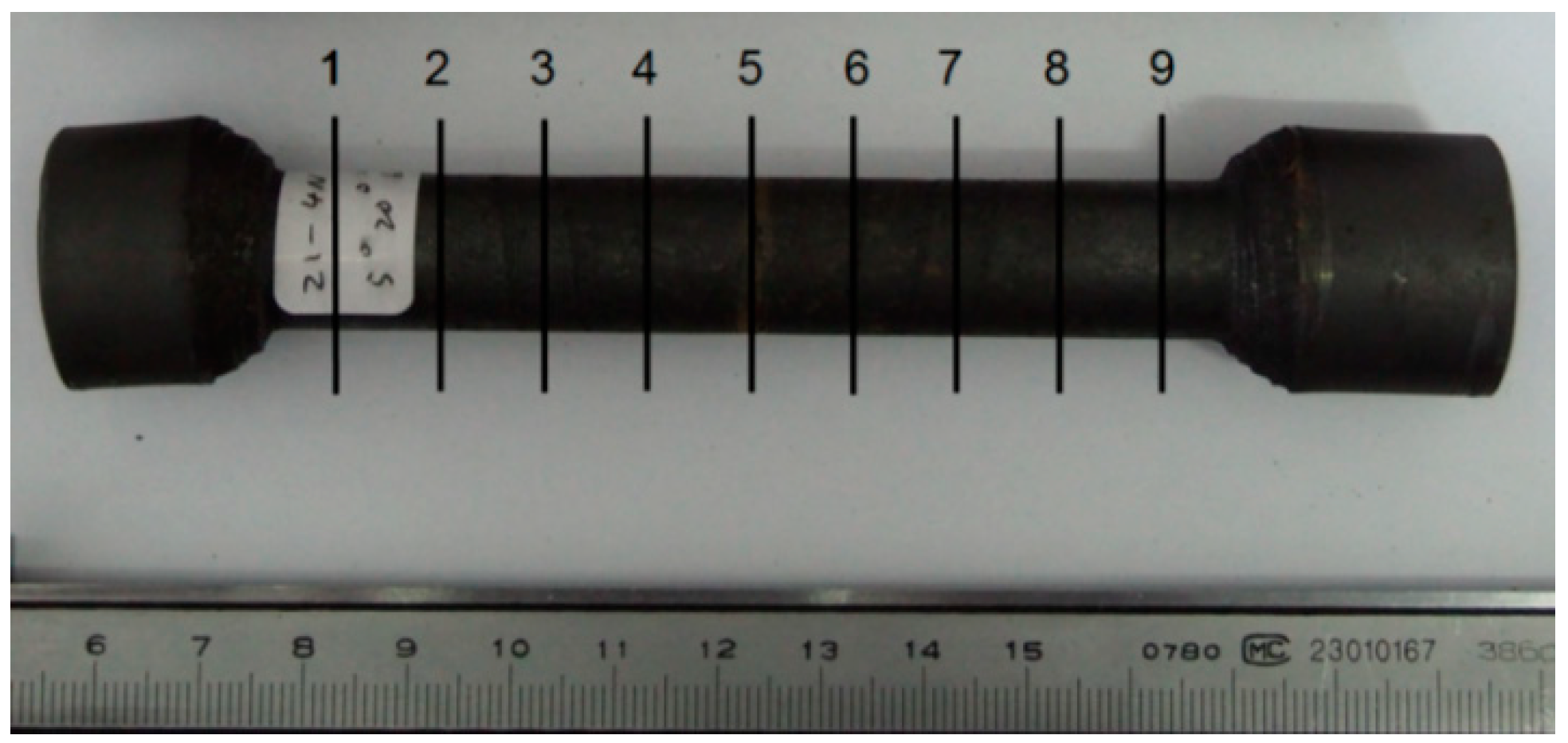
Surface quality is a main consideration of the CWR product. Once the area reduction ratio and the rolling temperature are fixed, surface quality is affected by the stretching angle and forming angle. Dimensional uniformity is chosen as an evaluation indicator of surface quality in this study. Diameters at 9 positions are measured, as shown in Figure 4, each of the two positions is adjacent to 10 mm, and the position 5 is at the symmetry plane.
When the forming angle was kept the same, diameters variations are more serious at a smaller stretching angle, as shown in Figure 5. With the forming angle of 25°, the maximum difference of the measured diameters is 1.48 mm at stretch angle of 3°, but at the stretch angle of 7°, the maximum difference decreased to 0.1 mm. This diameter difference was due to necking. The necking can be predicted by the equation: F a π d 2 σ 4 , where F a is the total axial force, d is the diameter after rolling, and σ is the yield stress of the material rolled. However, because of the complexity of the deformation zone geometry and the deformation mechanism, the theoretical analysis of the CWR process is difficult [28]. In this study, for simplicity, the acting force F was divided into two parts, one is affected by stretching angle F β and the other is affected by the forming angle F a . From the view of stretching angle, the acting force F β on the billet can be decomposed to axial force F β a and tangential force F β t , where F β a = F β cos β . When the stretching angle β is smaller, the axial force F β a is larger. In the research of Peng et al. [29], the total axial force was affected by the stretching angle β , and the value decreased linearly with the increase of stretching angle. As such, a greater stretching angle leads to a smaller axial force. The axial force can promote the axial flow of the metal, so the axial flow is more sufficient with larger axial force. But a heavier axial force may cause necking and the diameters after rolling were decreased. Therefore, a larger stretching angle is better for diameter uniformity.
When the stretching angles were the same, diameters at larger forming angle experienced more serious changes, as illustrated in Figure 3; Figure 6. From the view of forming angle, for simplicity, the acting force F α can be divided into axial force F α a and radial force F α r , where the axial force F α a = F α sin α . The axial force F α a is larger at a larger forming angle. Similar conclusion was presented in Hu’s study [27]. As such, when the forming angle is 35°, the rolled parts showed a slight necking, and the maximum diameters difference was 1.02 mm. Therefore, a smaller forming angle is beneficial to the uniformity of diameters.

4.2. Central Quality

Central quality is another concern of the CWR process. Central cavity is a serious defect in the solid products of cross wedge rolling, which weakens the mechanical strength of the workpiece and eventually results in product failure [23]. Many works had been done to reveal the formation of central cavity during the CWR process. Fu and Dean [30] summed up the reasons as: (a) development of alternating stress and shear stress in the central region of the billet in a similar way to the Mannesmann effect; (b) accumulation of microfracture due to the loading cycle; (c) torsion between portion of different diameter in a workpiece; (d) large inclusions in the material. In this study, only a single step was rolled and no obvious torsion was found in the rolled parts. Therefore, central cavities were unlikely formed due to the torsion. Recently, most studies about the central cavity have been focused on the alternating stress cycle and shear stress [31,32,33]. It is believed that larger shear stress causes central cavities to initiate, grow and coalesce in a more serious way. The number of stress cycles has a same effect.
In order to observe the central quality, rolled parts were cut at the symmetry plane 5 by wire cutting, and then the cross sections were polished with abrasive paper. Figure 7 shows the central quality of various parameters.
When α = 20 ° and α = 25 ° , at all the chosen stretching angles, the rolled parts have a central cavity. Obviously, the shape of cavities shows the morphology of shear damage. In the CWR process, the metal deformed in three directions: axial, radial and lateral. The axial and radial deformation are necessary, but the lateral deformation should be controlled which will cause a shear stress in the cross section. The shear stress is a main cause of central cavities.
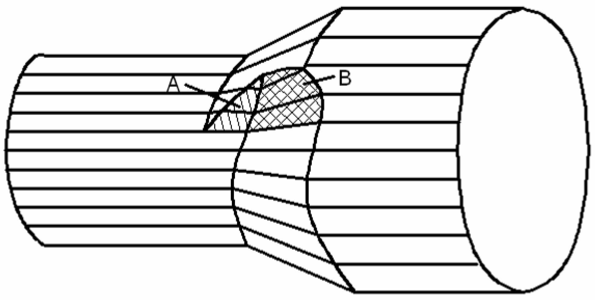
As shown in Figure 8, contact areas during CWR process can be simplified into two portions: A and B. Area A contacted with the top surface of the roller. Area B contacted with the side surface of the wedge shape dies. The metal under surface A was forced to flow in radial direction, but meanwhile, the metal was also prone to deform in a lateral direction. When the stretching angle increased, the area A increased, causing a more serious lateral deformation. Also, as the shear stress at the central area of the cross section increased, the central area was more prone to be damaged to form cavities.
However, along with the increases of stretching angle, the rolling radius of rolled part increases [34], which will lead to a decrease of the rolling cycles of the CWR process. Moreover, as shown in Figure 1, the total length of the wedge type dies will decrease while the stretching angle increases. Taking α = 25 ° as an example, when β = 3 ° , the total length of the wedge type dies were 1303 mm, when β = 7 ° , the total length decreased to 648 mm, with the differences being obvious. So, with a larger stretching angle, the whole deformation process was finished in a fewer cycles. This meant the action cycles of shear stress was fewer and the central area was less likely to be damaged. As such, the influence of shear stress and action cycles on the central damage was mutually weakened. Therefore, the influence of the stretching angle on central quality is not obvious.
The influence of the forming angle on central quality is shown in Figure 7. With the increase of the forming angle, the central damage got smaller, and when α 30 ° , no central damage was found. At β = 7 ° , when α = 20 ° , the workpiece has a cavity of about 2.9 mm2 in area, when α = 25 ° , the cavity decreases to about 1.4 mm2 in area. No cavity was found when α = 30 ° and α = 35 ° . Along with the increase of forming angle, the area A was kept the same, but the shape of area B became steeper. This caused a larger axial force, which was good for the metal’s axial deformation and the lateral deformation became smaller. Consequently, the shear stress at the cross section got smaller, and central cavities were less likely to be nucleated. Meanwhile, the rolling radius of the rolled part increased with the increase of the forming angle [34], which caused the rolling cycles to decrease. The wedge type dies got shorter with a larger forming angle. When α = 35 ° , the total length was 1215 mm, which is a little smaller than that of α = 25 ° . As such, the cyclic number of shear deformation decreased [23]. Smaller shear stress and the less frequent cycles of shear stress led to a better central quality at a larger forming angle.

5. Conclusions

In this paper, a full permutation of three stretching angles and four forming angles was designed for the CWR forming of 21-4N. The influences of the stretching angle and forming angle on the surface quality and central quality were experimentally investigated. The following conclusions can be drawn:
(1)
A larger stretching angle and smaller forming angle are good for the surface quality. When the stretching angle is 7° and forming angle is 20°, the surface quality reaches the best level.
(2)
The influence of forming angle on central quality is significant. When the stretching angles are 5° and 7°, no damage was found at the central area with the forming angle of 30° and 35°.
(3)
Considering the balance of surface quality and central quality, when forming a 21-4N workpiece with an area reduction of 65%, stretching angle of 7° and forming angle of 30° can be chosen as suitable parameters for cross wedge rolling.

Funding

This work is financially supported by the National Natural Science Foundation of China (grant No. 51505026) and Fundamental Research Funds for the Central Universities (grant No. FRF-BD-17-003A).

Conflicts of Interest

The author declares no conflicts of interest.

References

  1. Wang, Y. Introduction to Engine Valvetrains; SAE International: Warrendale, PA, USA, 2007. [Google Scholar]
  2. Li, M.; Sun, Y. Review of forming technique development for engine valves. China Met. Form. Equip. Manuf. Technol. 2007, 42, 18–21. [Google Scholar]
  3. Xiao, X.; Zhang, Z.; Sun, Y.; Liu, Y.; Chen, Y.; Luo, T. Product defect reasons analysis and quality control strategy in electric upsetting deformation. Hot Work. Technol. 2001, 30, 45–48. [Google Scholar]
  4. Ji, H.; Liu, J.; Wang, B.; Zhang, Z.; Zhang, T.; Hu, Z. Numerical analysis and experiment on cross wedge rolling and forging for engine valves. J. Mater. Process. Technol. 2015, 221, 233–242. [Google Scholar] [CrossRef]
  5. Ji, H.; Liu, J.; Wang, B.; Zheng, Z.; Huang, J.; Hu, Z. Cross-wedge rolling of a 4Cr9Si2 hollow valve: Explorative experiment and finite element simulation. Int. J. Adv. Manuf. Technol. 2015, 77, 15–26. [Google Scholar] [CrossRef]
  6. Ji, H.; Liu, J.; Wang, B.; Fu, X.; Xiao, W.; Hu, Z. A new method for manufacturing hollow valves via cross wedge rolling and forging: Numerical analysis and experiment validation. J. Mater. Process. Technol. 2017, 240, 1–11. [Google Scholar] [CrossRef]
  7. Hu, Z.; Yang, C.; Wang, B. Development of part rolling technology in China. J. Mech. Eng. 2012, 48, 7–12. [Google Scholar] [CrossRef]
  8. Pater, Z. Tools optimization in cross-wedge rolling. J. Mater. Process. Technol. 2003, 138, 176–182. [Google Scholar] [CrossRef]
  9. Li, Q.; Lovell, M.R. The establishment of a failure criterion in cross wedge rolling. Int. J. Adv. Manuf. Technol. 2004, 24, 180–189. [Google Scholar] [CrossRef]
  10. Li, Q.; Lovell, M.R. Cross wedge rolling failure mechanisms and industrial application. Int. J. Adv. Manuf. Technol. 2008, 37, 265–278. [Google Scholar] [CrossRef]
  11. Wang, M.; Li, X.; Du, F. Analysis of Metal Forming in Two-Roll Cross Wedge Rolling Process Using Finite Element Method. J. Iron Steel Res. Int. 2009, 16, 38–43. [Google Scholar] [CrossRef]
  12. Pater, Z.; Gontarz, A.; Tofil, A. Analysis of the cross-wedge rolling process of toothed shafts made from 2618 aluminium alloy. J. Shanghai Jiaotong Univ. Sci. 2011, 16, 162–166. [Google Scholar] [CrossRef]
  13. Pater, Z. Cross-Wedge Rolling of Shafts with an Eccentric Step. J. Iron Steel Res. Int. 2011, 18, 26–30. [Google Scholar] [CrossRef]
  14. Bulzak, T.; Pater, Z.; Tomczak, J. Numerical and experimental analysis of a cross wedge rolling process for producing ball studs. Arch. Civ. Mech. Eng. 2017, 17, 729–737. [Google Scholar] [CrossRef]
  15. Peng, W.F.; Zhang, J.H.; Huang, G.X.; Liu, W.P.; Shu, X.D.; Zhu, J. Stress distributions during the cross-wedge rolling of composite 42CrMo/Q235 laminated shafts. Int. J. Adv. Manuf. Technol. 2016, 83, 145–155. [Google Scholar] [CrossRef]
  16. Wu, Z.J.; Peng, W.F.; Shu, X.D. Influence of rolling temperature on interface properties of the cross wedge rolling of 42CrMo/Q235 laminated shaft. Int. J. Adv. Manuf. Technol. 2017, 91, 517–526. [Google Scholar] [CrossRef]
  17. Sun, B.; Xu, J.; Peng, W.; Shu, X.; Yin, A.; Huang, G. Experimental investigation on cross wedge rolling of composite 42CrMo/Q235 laminated shaft. Int. J. Adv. Manuf. Technol. 2018, 96, 895–903. [Google Scholar] [CrossRef]
  18. Çakırcalı, M.; Kılıçaslan, C.; Güden, M.; Kıranlı, E.; Shchukin, V.Y.; Petronko, V.V. Cross wedge rolling of a Ti6Al4V (ELI) alloy: The experimental studies and the finite element simulation of the deformation and failure. Int. J. Adv. Manuf. Technol. 2013, 65, 1273–1287. [Google Scholar] [CrossRef]
  19. Li, J.; Wang, B.; Ji, H.; Huang, X.; Tang, X.; Ma, W. Effects of the cross-wedge rolling parameters on the formability of Ti–6Al–4V alloy. Int. J. Adv. Manuf. Technol. 2017, 92, 2217–2229. [Google Scholar] [CrossRef]
  20. Wei, J.; Shu, X.; Tian, D.; Xiang, W.; Wei, Y.; Han, S.; Peng, W.; Liu, C.; Wang, Y.; Niu, B. Study in shaft end forming quality of closed-open cross wedge rolling shaft using a wedge block. Int. J. Adv. Manuf. Technol. 2017, 93, 1095–1105. [Google Scholar] [CrossRef]
  21. Wei, Y.; Shu, X.; Han, S.; Tian, D.; Wei, J. Analysis of microstructure evolution during different stages of closed-open cross wedge rolling. Int. J. Adv. Manuf. Technol. 2018, 95, 1975–1988. [Google Scholar] [CrossRef]
  22. Tian, D.; Shu, X.; Zhu, Y.; Xu, C.; Han, S.; Zhu, D.; Peng, W. Closure laws of void in the core of cross wedge rolling shaft based on the floating-pressure method. Int. J. Adv. Manuf. Technol. 2018, 98, 2905–2916. [Google Scholar] [CrossRef]
  23. Yang, C.; Dong, H.; Hu, Z. Micro-mechanism of central damage formation during cross wedge rolling. J. Mater. Process. Technol. 2018, 252, 322–332. [Google Scholar] [CrossRef]
  24. Egea, A.J.S.; Rojas, H.A.G.; Celentano, D.J.; Peiró, J.J. Mechanical and metallurgical changes on 308L wires drawnby electropulses. Mater. Des. 2016, 90, 1159–1169. [Google Scholar] [CrossRef]
  25. Egea, A.J.S.; Rojas, H.A.G.; Celentano, D.J.; Peiró, J.J.; Cao, J. Thermomechanical analysis of an electrically assisted wire drawing process. J. Manuf. Sci. Eng. 2017, 139, 111017. [Google Scholar] [CrossRef]
  26. Zheng, M.; Zhang, Z.; Song, L.; Mo, D. High temperature compression behavior of 21-4N valve steel in hot working process. Hot Work. Technol. 2012, 41, 46–48. [Google Scholar]
  27. Hu, Z.; Zhang, K.; Wang, B.; Shu, X.; Yang, C. Technology and Numerical Simulation of Parts Forming by Cross Wedge Rolling; Metallurgical Industry Press: Beijing, China, 2004. [Google Scholar]
  28. Pater, Z. Theoretical method for estimation of mean pressure on contact area between rolling tools and workpiece in cross wedge rolling processes. Int. J. Mech. Sci. 1997, 39, 233–243. [Google Scholar] [CrossRef]
  29. Peng, W.; Jiao, S.; Shu, X.; Zhang, K. Feasibility of cross wedge rolling asymmetric shaft parts. J. Cent. South Univ. (Sci. Technol.) 2012, 43, 4280–4285. [Google Scholar]
  30. Fu, X.P.; Dean, T.A. Past developments, current applications and trends in the cross wedge rolling process. Int. J. Mach. Tools Manuf. 1993, 33, 367–400. [Google Scholar] [CrossRef]
  31. Cao, F.; Yang, C.; Zhang, K.; Hu, Z. Effect of alternating times on the internal rarefaction of cross wedge rolling. Forg. Stamp. Technol. 2005, 30, 39–41. [Google Scholar]
  32. Zhou, J.; Yu, Y.; Zeng, Q. Analysis and experimental of internal voids in multi-wedge cross wedge rolling stepped shaft. Int. J. Adv. Manuf. Technol. 2014, 72, 1559–1566. [Google Scholar] [CrossRef]
  33. Pater, Z. Preliminary analysis of a rotary compression test. Adv. Sci. Technol. Res. J. 2018, 12, 77–82. [Google Scholar] [CrossRef]
  34. Wang, B.; Hu, F.; Hu, F.; Hu, Z. Experimental research on rolling radius of formed parts for cross wedge rolling. J. Mech. Eng. 2010, 46, 22–27. [Google Scholar] [CrossRef]
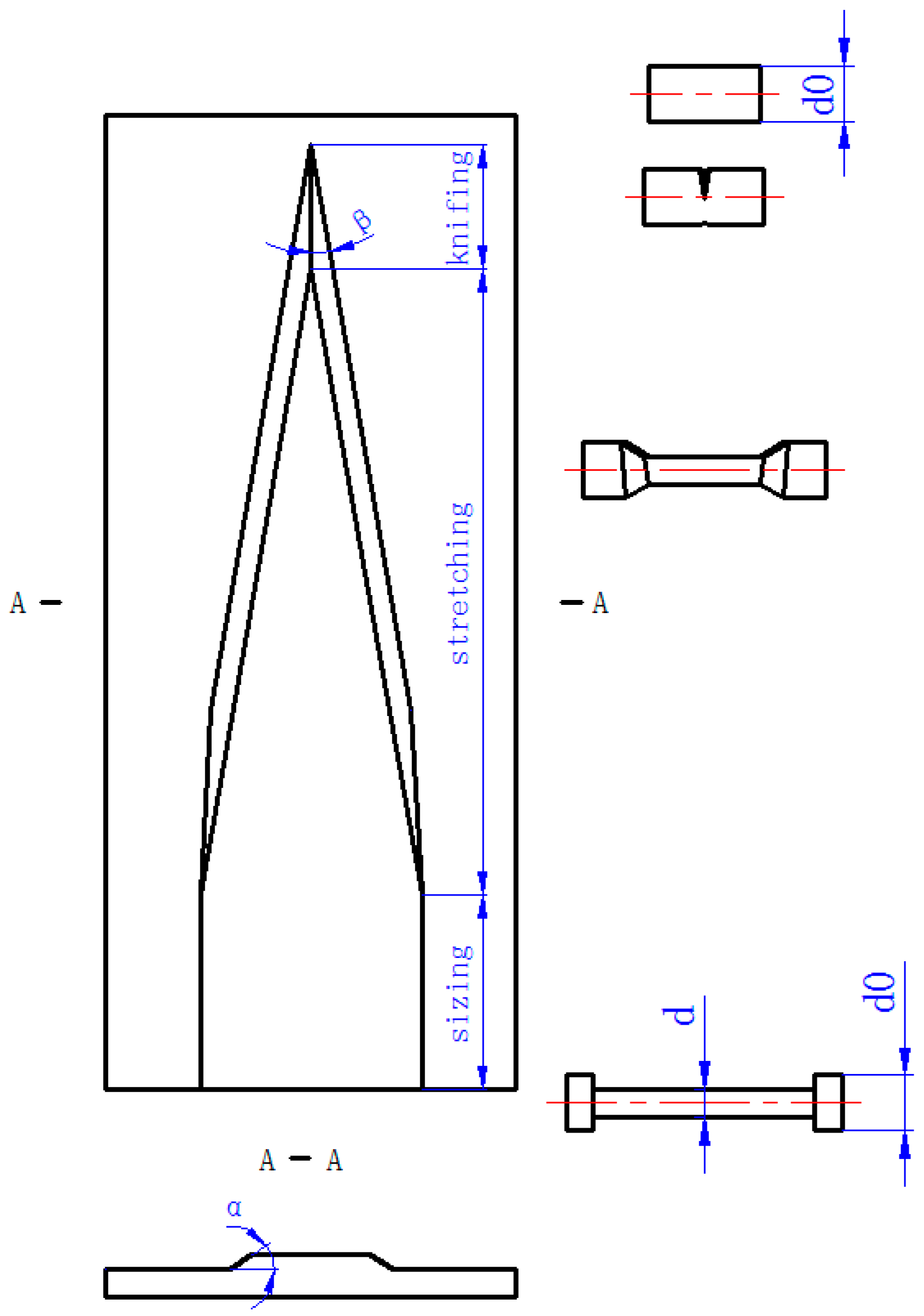
Figure 1. CWR (cross wedge rolling) process.
Metals 09 00039 g001
Figure 2. H500 mill.
Metals 09 00039 g002
Figure 3. Some rolled parts (β = 7°).
Metals 09 00039 g003
Figure 4. Positions of Diameters measured.
Metals 09 00039 g004
Figure 5. Diameters at the measured positions ( α = 25 ° ).
Metals 09 00039 g005
Figure 6. Diameters at the measured positions ( β = 7 ° ).
Metals 09 00039 g006
Figure 7. Central quality at position 5 of different parameters.
Metals 09 00039 g007
Figure 8. Contact area during CWR process.
Metals 09 00039 g008
Table 1. The main technical parameters of H500.
ParameterValue
Motor power (KW)30
Roller diameter (mm)500
Max rolling diameter (mm)40
Max rolling width (mm)400
Max rolling speed (rpm)8.45
Table 2. The chemical composition of 21-4N (weight percentage, %).
CSiMnPSCrNiCuMoW
0.520.148.980.0280.00221.303.670.300.050.03
VTiAlBNbPbSnCoNFe
0.080.010.0030.0010.030.0010.0050.090.43Bal.
Table 3. Tensile Strength of 21-4N.
ItemTemperature (℃)
25500550600650700750800
Tensile Strength, Ultimate (MPa)950650600550500450370300
Tensile Strength, Yield (MPa)580350330300270250230200
Table 4. Rolling results at various roller parameters.
ItemStretching Angle (°)Forming Angle (°)Surface QualityCentral Quality
Max Diameter DifferenceSurface Appearance
13201.46 mm, slight neckingspiralcavity
2251.48 mm, slight neckingspiralcavity
330failed, tension fracture--
435failed, tension fracture--
55200.24 mmslight spiralcavity
6250.44 mmspiralslight cavity
7302.38 mm, slight neckingspiralgood
8355.2 mm, neckingspiralgood
97200.08 mmgoodcavity
10250.1 mmgoodcavity
11300.36 mmspiralgood
12351.02 mm, slight neckingspiralgood