The Effect of Stress Relief on the Mechanical and Fatigue Properties of Additively Manufactured AlSi10Mg Parts
by
 ,
,
Busisiwe J. Mfusi
1,2,*, 
Ntombizodwa R. Mathe
2,*,
Lerato C. Tshabalala
2 and
Patricia AI. Popoola
1 1
Department of Chemical and Metallurgical Engineering, Tshwane University of Technology, Staatsartillerie Rd, Pretoria West, Pretoria 0183, South Africa
2
National Laser Centre, Council for Scientific and Industrial Research, Meiring Naudé Road, Brummeria, Pretoria 0185, South Africa
*
Authors to whom correspondence should be addressed.
Metals 2019, 9(11), 1216; https://doi.org/10.3390/met9111216
Submission received: 25 July 2019
/
Revised: 8 October 2019
/
Accepted: 14 October 2019
/
Published: 12 November 2019
(This article belongs to the Special Issue Additive Manufacturing of Metals)
Abstract
:The heating and cooling profiles experienced during laser additive manufacturing results in residual stresses build up in the component. Therefore, it is necessary to perform post build stress relieving towards the retention and improvement of the mechanical properties. However the thermal treatments for conventional manufacturing do not seem to completely accommodate these rapid heating and cooling cycles of laser processing techniques such as powder bed fusion. Characterizations such as density measurements on the samples were performed employing the Archimedes principle; hardness testing was performed on the Zwick micro/macro (Hv) hardness tester, SEM and Electron backscatter diffraction (EBSD). Fracture toughness and crack growth was conducted on a fatigue crack machine. All characterization was done after stress relieving of Selective Laser Melting (SLM) produced samples at 300 °C for 2 hrs was performed in a furnace. The mechanical properties appear to be rather compromised instead of being enhanced desirably. As-built SLM produced tensile specimens built in different directions exhibited significantly favorable mechanical properties. However, post stress relieve thermal treatment technique deteriorated the strength while increasing the ductility significantly. Nonetheless, fatigue crack growth and fracture toughness illustrated positive outcome in terms of fatigue life on SLM produced AlSi10Mg components in application.
1. Introduction
Additive manufacturing (AM) is a new technology that has made its mark as an innovative and flexible manufacturing technology [1]. Continuously, there is a need for the development of this technique, with the main objective being to reach 100% component density [2,3]. The additive manufacturing of aluminum alloys in particular finds recent applications in the aerospace, rail and automotive industries for structural and non-structural parts, which are usually die casted. In particular, the powder bed fusion processing of aluminum alloys has gained interest in the aerospace, rail and automotive industries due to the versatile nature of the process. The shapes of the components are generally attained from rigidity-focused strategies. Usually low stress requirements are often the objective for these components relative to stressful loading circumstances where finite-life fatigue resistance should be considered as distinctively possible such as circumstances where load or vibrations counteracting on component could be extreme [4]. Fatigue resistance crack propagation relative to the direction of the load is inherently dependent to anisotropy of the process of manufacturing. It is common knowledge that defects that are found on the surface are the most dangerous of them all since crack propagation is most likely to be initiated on the surface. In AM applications, majority of failures observed are those that generally instigated from the surface where there are defects [4].
Silicon based aluminum alloys such as AlSi10Mg, AlSi12, etc. are currently used for laser AM and these are characterized by good castability, low shrinkage and moderately low melting temperature and AlSi10Mg is one of the most common alloys characterized with a hypoeutectic composition [5,6]. Prashanth et al. [7] studied the heat treatment of hypereutectic Al–Si alloys, which are said to have a wide application in the automobile and aerospace sectors due to their high wear and corrosion resistance.
During laser AM processing, the rapid heating and cooling of the laser processing results in the residual stresses build up. These residual stresses affect the properties of the components such as the ultimate tensile strength and the fatigue life [8]. It is said to be common knowledge that AM material has comparatively lower fatigue resistance than traditionally manufactured materials in the as-built condition, the reason being that fatigue life is affected directly by impurities and the inhomogeneity of the microstructure [9]. In this case, post heat treatment is necessary in order to relieve the residual stresses while maintaining the desired mechanical properties.
For instance, Cabrini et al. [10] performed various heat treatment techniques on the AlSi10Mg samples with various direct metal laser sintering (DMLS). These were stress relieving, annealing at high temperature and water quenching. Their results determined that annealing resulted in intensification to the matrix of aluminum phase with precipitation of rounded silicon on the surface also. Fiocchi et al. [11] studied the low temperature annealing of Selective Laser Melting (SLM) produced AlSi10Mg. After stress relieving at 263 °C on the as built samples, minor microstructural differences were observed. However, for heat treatment at 294 °C the silicon network appeared to be disconnected. Other work by Fousova et al. [12], investigated the modifications in the microstructure and mechanical properties of additively manufactured AlSi10Mg alloy after exposure to temperatures of 120–180 °C. The current, heat treatment profiles, mainly die casting used for AM parts, are adapted from conventional profiles, which have been shown to affect the AM parts negatively in some instances [13].
Therefore in order to improve the fatigue performance of AlSi10Mg, T6 heat treatment, processes such as solution treatment at 520 °C, water quenching and artificial ageing at 160 °C, which are also known as peak-hardening have been used [14]. Microstructural coarsening and material softening during annealing of SLM produced AlSi12 were reported and revealed the same results as conventionally cast material [15].
This paper will focus on the effect of stress relieving on the microstructure, porosity, mechanical properties and fatigue life of SLM produced AlSi10Mg samples with a focus on the build direction effect. It is a continuation of the previously published work conducted by the authors investigating the effect of build direction on the as-built SLM samples using AlSi10Mg [16]. This is because although the effect of the build direction of powder bed fusion manufactured Ti6Al4V has been extensively studied, there is little information on the AlSi10Mg alloy.
2. Materials and Methods
2.1. Powder Bed Fusion Processing
AlSi10Mg powder with a spherical morphology and particle size distribution of 30–65 µm was purchased from TLS Technik GmbH, Germany, and it was used as received (see reference [6]). The study was carried out on specimens produced by the SLM Solution M280 GmbH from Lubeck in Germany using a laser power of 150 W, 1000 mm/s scan speed, 50 µm hatch spacing and 50 µm powder layer thickness fixed processing parameters (the image of the samples on the base late is presented in previous work [16]). The samples were built in the XY, 45° and Z orientations. Tensile, fatigue and crack growth samples (three of each) were prepared according to the images in Scheme 1. Post build stress relieving on the specimens was carried out in a rotary furnace using a temperature of 300 °C and hold time of 2 h then furnace cooled to room temperature.
2.2. Characterization Techniques
Density measurements on the samples were performed using the Ohaus densitometer employing the Archimedes principle with ethanol as a liquid medium. For testing the mechanical properties (ASTME8), the 20kN Zwick/Roell Tensile/Compression tester GmbH from Radeberg in Germany was used, while hardness testing was performed on the Zwick micro/macro (Hv) hardness tester GmbH from Radeberg in Germany. The microstructures of the polished samples after etching with Keller’s reagent were viewed on the optical microscope. The samples were also analyzed for phase and grain information using a Zeiss LEO 1530-FESEM fitted with the Oxford Energy Dispersive Spectroscopy (EDS) and Hardware Lab Kit (HKL) Electron Backscatter Diffraction (EBSD) detector GmbH from Radeberg in Germany. The fractured tensile samples also underwent fracture analysis on the JEOL JEM-210 SEM from Peabody in USA. A 1342 Instron 30 kN fatigue crack machine from Norwood in US was used to conduct fracture toughness and fatigue crack growth tests according to ASTM399. The dimensions of the samples were as seen in Scheme 1, with a notch length of 7.37 mm for both fatigue crack growth and fracture toughness samples. The load used on the samples was 156 MPa, cycling at a rate of 2.1 mm/min and frequency of 15 Hz.
3. Results and Discussion
3.1. Density and Porosity Measurements
The density results of the AlSi10Mg as-built samples were investigated and presented by Mfusi et al. [16], where the average density was 2.68 g/cm3, with relative densities above 99% for the samples in different build directions. However, after stress relieving at 300 °C the density values dropped drastically to 2.58–2.61 g/cm3, which were 0.07–0.1 g/cm3 lower than as-built, presented in Table 1. It was also observed that the porosity values were higher at 2.67–3.81%, which was above the accepted levels for applications.
This behavior was also observed by Calignano [17], where they also determined that stress relief led to a decline the density and mechanical properties of the specimen. Ahmed [5] determined that the greatest challenge in producing aluminum alloys parts by SLM technique was to minimize porosity, which is the major effect of the relative density as aluminum alloys are easily subjects to oxidation during processing, stimulating pore formation. Therefore, more research is needed to address the impact of heat treatment temperatures on the properties of the SLM produced samples in order to optimize the properties for intended applications [18].
3.2. Hardness Measurements
The Vickers hardness method was used to measure the hardness of the samples in different orientations after stress relieving and is presented in Table 2.
After stress relief the samples suffered an enormous drop in hardness from 126–128 HV for the as-built samples [16], to 46–49 HV as shown in Table 2. This illustrated the uncertainty of the stress relieving method undertaken towards the improvement of the mechanical properties of SLM produced AlSi10Mg, irrespective of the build direction. However, the largest drop in hardness was observed for batch A that was built in the 0° direction. This decrease in hardness after stress relief in the SLM produced aluminum alloy study was also observed by Fiocchi et al. [11] and Aboulkhair et al. [16,19], where a negative response was seen after heat treating the AlSi10Mg alloy using the T6 treatment and stress relief at 300 °C. In their work, stress relief showed a significant decrease in hardness of up to 66%, compared to the decrease of up to 62% obtained in this investigation. They attributed this behavior to the material softening that was seen to expose the additively manufactured component’s weakness for application that requires high hardness properties. Trevisan et al. investigated the effect of stress relieving on SLM produced AlSi10Mg parts and also reported negative results as well [17], which might not render the temperature profiles viable for the improvement of properties, however the process is sometimes necessary in order to relieve the residual stresses obtained in SLM produced parts.
3.3. Microstructure Analysis
The evolution of the microstructures as a function of heat treatment is an important aspect of metallurgical evaluation as it is related to the mechanical properties of the samples. Therefore, the microstructures of the SLM processed AlSi10Mg samples after stress relieving were taken and these are presented in Figure 1a–c, demonstrating the three build directions at 50× magnifications.
Figure 1a–c illustrates that post stress relieving, the grain boundaries disappeared completely and a different homogeneous “sand like” structure was observed. The microstructural observation acquired a big change in the morphology compared to the as-built micrographs, which had scale-like morphologies [16], as presented by Mfusi et al. From the observation, this structure exhibited a rough surface, which was speculated to be a result of the silicon (depicted by yellow arrow) and aluminum (depicted by white arrow) being uniformly distributed. Brandl et al. [15] also observed the same change in the microstructure after performing peak hardening heat treatment for SLM processed AlSi10Mg. Finer silicon particles were observed in 45° orientation relative to 0° and 90° orientation, which were anticipated to be attributed by the defects contained in the specimen. Built direction played a role as it was observed also that 0° orientation had more courser particles than the rest. Tang determined that there were three stages that silicon undergoes during stress relief heat treatment where silicon and Mg2Si precipitates, spheroidization of precipitates and silicon particles coarsening [20].
Fousova et al. [12], explained the effect as the comparative infringement of the silicon network causing the coarsening of distinct Si particles, which are observed in all the images. Zhang et al. [21] also stated that after stress relieving, there is a diffusion of silicon dendrites into a discontinuous state.
3.4. Electron Backscatter Diffraction (EBSD)
EBSD was performed on the as-built and stress relieved samples to determine the effect that stress relieving has on the phases and grains produced by SLM processing. Table 3 presents the phase fractions of the main elements of AlSi10Mg alloy for the as built samples, as well as for samples after stress relieve heat treatment respectively, for the three build directions.
In Table 3, 0° orientation samples, before stress relief had a minimal amount of the main elements and a high percentage of zero solution. After stress relieving an increase in aluminum and especially silicon was observed on the surface of the sample, this supports the observation made in Figure 1 OM images. The 45° orientation showed a huge fraction of silicon element and a significant amount of aluminum before stress relieve. After stress, a huge rise to zero solution is seen. On the other hand 90° orientation showed to have an insignificant change before and after stress relieve with a drop in the Mg2Si as compared to other orientations. During the SLM process, Mg2Si appeared upon final solidification while appearing beneath solidus temperature below equilibrium circumstances. Mg generally melted into the aluminum matrix considering that it was not present as any intermetallic phases during solidification at equilibrium as stated by Tang et al. [20] then the increase of Mg2Si and silicon after heat treatment was caused by the precipitation onto the surface.
Figure 2 shows the pictures of the electron backscatter diffraction results as-built and after stress relief.
Figure 2a showed cellular and dendritic growth, which was also observed in the optical microstructure. Wu et al. [22] attributed these cellular growths as long cells that are formed as a result of cooling conditions in place of dendrites. The dark region seen in Figure 2b,c was drastically eradicated in Figure 2e,f, where more silicon and aluminum were visible. These dark regions, according to Wu et al. [22] and Mathe et al. [6], are aluminum grains that also contain Al–Si eutectic, which is difficult to distinguish from cell boundaries because of the disappearance of diffraction data. Figure 2d has developed roughness on its surface that looks “pimple” like as compared to Figure 2a before stress relief. The same roughness was observed in the optical microstructures.
Heat treatments at high temperature can encourage the combination of second phases as well as change in distribution of those phases [23]. This was observed in Figure 2c after stress relief. In these samples, the columnar and equiaxed grains were observed before stress relief. These have been proposed to be formed directly by solidification that takes places as cellular dendrites as a consequence of rapid cooling with little information for the mechanism of formation [22,24]. In the optical microstructure, it was stated as silicon segregation to the grain boundaries as a result of rapid cooling [19]. Aboulkhair et al. [25] and Li et al. [23] proposed that these silicon rich boundaries isolated by the aluminum grains and the cellular structure are the fine eutectic composed of aluminum grains with silicon particles. Longer columnar grain sizes after stress relief are seen even though they were covered by the black region. In Figure 2f some Mg2Si precipitation was also observed and the silicon phase that was more visible on the as-built samples, while after stress relief it seemed to fade.
Wu et al. [22] stated that the reason SLM processed AlSi10Mg is optimum in strength is because the larger aluminum regions contains silicon particles, which are surrounded by the thick eutectic boundaries that prevents dislocation movement inside the aluminum grains. In these pictures, it is observed that the dark lines seen before stress relieved are removed. These dark lines were also observed by Mathe et al. [6] for SLM produced AlSi10Mg, which were attributed as shear bands that are caused by the shear strain from the manufacturing process. Grain refinement was also observed on the samples after stress relieving.
3.5. Tensile Strength after Stress Relieving
To determine the effect that build directions have on the mechanical properties of post stress relief tensile specimen tensile measurements were performed. The average values of triplicate measurements are presented in Figure 3 and Figure 4. In the previous study of the as-built AlSi10Mg SLM samples [16], orientation 90° had the highest ultimate tensile strength compared to the other orientations. After stress relieving, the Ultimate Tensile Strength (UTS) values dropped drastically from 420–470 MPa as-built, [16], to 110–160 MPa. The same was observed also for the modulus values in Figure 3b.
In Figure 3a, 0° and 90° orientation exhibited the higher UTS values compared to 45° orientation. This is in contrast with the as-built samples where the 0° orientation had the lowest UTS value and the 90° orientation still had the highest value. The drastic decrease in the mechanical properties of the SLM produced has also been observed by Brandl et al. [15,19], for the same material, which they attributed to the changes in the grain structures and phases of the samples present when heat treatment occurs above the eutectic temperature.
The yield strength results in Figure 4a showed higher values for the 0° and 90° orientation, with the values ranging from 61–96 MPa. The 90° orientation was ductile but could only endure elastic deformation up to just below 88.1 MPa, this might be because of the number of pores suffered by the material for the as-built samples [16]. The yield strength of the 45° orientation was radically dropped by a magnitude of approximately 4.3 times to 108 MPa. Figure 4b showed the elongation results of the samples after stress relieving, where for all the build directions the elongation increased significantly from 6.25–7.25 mm as-built [16] to 12.5–23 mm post stress relief. This means with stress relief the ductility of the material is drastically improved. The effect of post build stress relieving in this case had both a negative and positive impact with the most improvement seen for the elongation.
Represented graphically in Figure 5a are the stress–strain curves of the tensile tests after stress relieving. All the samples after stress relieve experienced Lueder’s bands during tensile testing (see Figure 5b), which was a result of high total elongation before fracture. This phenomenon occurs when a specimen that cannot yield to the given load, yields, which is also known as discontinuous yielding [3,7], the behavior is typically observed in the area where an increase in strain occurs without an increase in stress. It was observed in the comparison of mechanical properties that before stress relieving the samples had more strength and less ductility [16], however, after thermal treatment, in the attempt to acquire ductility, strength was compromised.
Zhang et al. [26] determined that stress relieve reduces the strengths and fatigue properties of the alloy significantly due to reduced solid solubility and the precipitation of the fine silicon as well as the demolition of the fine sub-structures within the aluminum grains. Li et al. [23,27] stated that even though heat treatment is required for quality improvement of a part by microstructural refinement, it has been found to decrease the UTS while increasing the ductility. This is as a result of the silicon trapped in the aluminum matric that precipitates to the grain boundaries, reducing the solid solution strength [12].
Rosenthal et al. [28], also reported a decline in the ductility that is inversely proportional to the strain rate, which suggests the effects of confined strain rate hardening had not taken place, and that the existence of the silicon phase could be predominantly the reason for this conduct. Brandao et al. [29] used stress relief to prevent the residual stress from distorting the components. The effect was the same as in this work, as it led to a drastic decrease in the static yield strength.
3.6. Fractography Analysis
Figure 6 illustrates the SEM morphology of the fractured surfaces from the tensile specimens before and after stress relieving. Figure 6a showed dense and smooth surface for the 0° orientation as-built samples, with fracture defects observed. Fracture observed to begin from the one end of the structure propagating to the other end.
The stress relieved samples, (Figure 6c–f), showed dimples, which illustrated the ductility that was desirable for the manufacturing of industrial parts, but in this case the tensile testing strength was proven to have been compromised. There was also an increase in the number of surface pores observed on the stress relieved samples compared to the as-built samples, which was in support of the Archimedes density and porosity results presented in Table 1.
Various defects were observed for the as-built samples, for instance in Figure 6b, ballus defects were observed and Dheyaa et al. [30] explains these ballus defects, marked with yellow arrows, to be unmolten or partly molten powder. According to Read et al. [13,31], these unmolten powder particles are a result of thick oxides layer existing on the particles, which did not allow full consolidation during processing. Defects such as unmolten powder and pores (marked in red), impacts the fatigue life of a component severely by reducing the effective load bearing area thus causing stress concentrations that consequently form static and dynamic strength reduction [15]. In Figure 6e, post stress relieving for the 45° orientation samples, the unmelted powder disappeared but there seemed to not be an apparent improvement in the mechanical properties. This was observed in the tensile results for orientation B, which had the highest elongation post stress relieve.
Figure 6c (90° orientation) specimen showed a ductile fracture with dimples, which suggests forced fracture. It was determined that there were micro-cavities formed where there were defects visible in Figure 6d–f post stress relieve [15,25,31,32]. These micro-cavities lead to more micro-cavities that join together to cause a fast growing tear in the structure. The tear spreads laterally to the interface between the melt pool core and the boundary, constantly along the fracture sides. This is due to the fact that the melt pool boundary is weaker than the melt pool core, containing a coarser microstructure and minimal content of silicon for the reduced grain boundary, which were also observed on the OM and EBSD microstructures. Overall post processing by stress relieve has shown the microstructure of the fracture surfaces of all three different orientations were similar. Ductility dimples are virtually the same with voids that develop and merge together. Zaretsky et al. [33] believe that the homogeneous spreading of sites is suitable for void nucleation all over the sample and these are the characteristics of SLM processing.
3.7. Fracture Toughness and Fatigue Crack Growth Rate Analysis
The stress relieved samples for the 90° orientation were further analyzed for fracture toughness and crack growth in order to determine the effect that the heat treatment process has on the properties. One orientation was chosen because all samples after stress relieve exhibited more or less the same mechanical properties. The samples were machined to dimensions specified in Scheme 1 and ASTM399, before undergoing the tests. According to Rosenthal [34], as-built AlSi10Mg relative to traditionally produced AlSi10Mg exhibited inferior fracture toughness properties so the samples were stress relieved before testing.
Figure 7 was plotted based on the Paris equation: da/dN = C (ΔK)m and the three states were marked in the graph. The Kq obtained were 29.51, 30.47 and 29.99 MPa.m1/2 for samples 1 to 3 respectively according ASTM399 standard for fracture toughness. Results show correspondence with those of Rosenthal [34], which were 30.4 MPa.m1/2 after stress relieving. These results show that even though the stress relieving profile use in this case resulted in a decline in strength, it increased the fatigue life of the samples as presented in Figure 8. The samples have dimple fractures, which Kobayashi [35] equated to nucleation–growth–coalescence of voids. According to Brandl [15], additively manufactured AlSi10Mg demonstrated an increase in fatigue life after thermal treatment compared to cast AlSi10Mg.
A representative sample was chosen from the three samples and is presented in Figure 8; it shows the propagation until the edge of the sample. The cleavage fracture was observed in these samples as “particle like” brittle phases where there were holes. These are called Griffith-like-microcrack as studied by Ruggieri and Dodds Jr. [36]. This is the microcrack that is nucleated then promptly spreads into the inner grain boundary to cause a fracture when it is not blocked by any obstructions in the grain boundary. It was observed in the gentleness of the steep of the graph in Figure 7 that the fracture was gradual. Therefore these samples failed due to nucleation overpowering various consecutive obstructions in the grains structures [37].
The fatigue crack growths results show that the samples were able to sustain the load for up to 75,000 cycles. The samples exhibited brittle propagation then dimples where it seemed to have tried to endure further before yielding to cracking. Aluminum alloys exhibited ductile fracture that formed dimples even though formation of dimples is dependent on shape, properties, volume fraction and condition of the particle matrix [35].
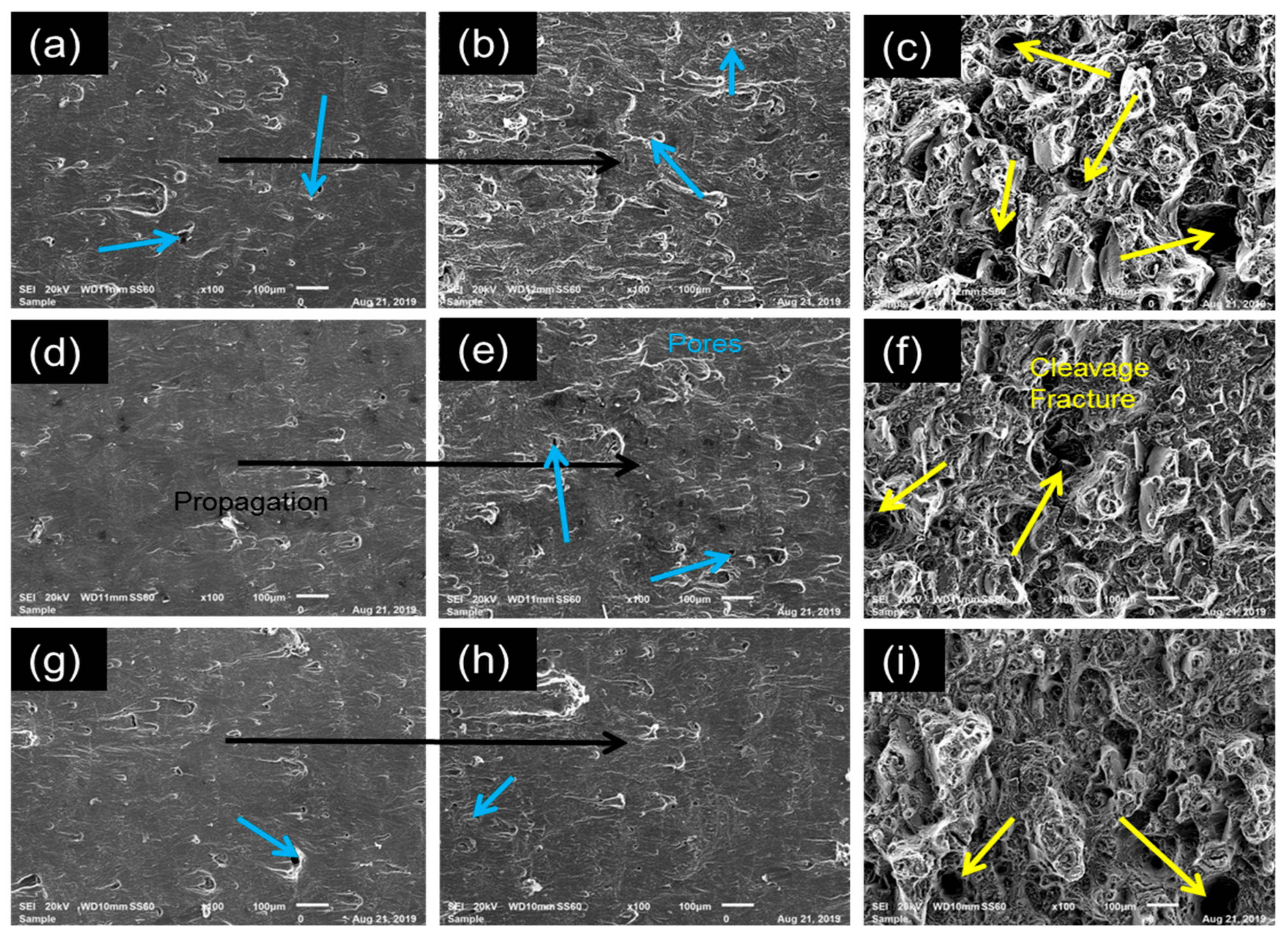
Figure 9 presents fatigue sample 1 (a,b,c), sample 2 (d,e,f) and sample 3 (g,h,i) of the fatigue crack growth sample. It was observed in sample 1 numerous pores that were anticipated to have assisted the crack to grow faster relative to sample 2 and 3.
There seem to have been an increase of propagation possibilities even after a certain number of obstructions in the grain structure that arose from the pores [35,36] resulting to rapid failure. Samples 3 displayed a smoother propagation before fracture relative to the other two samples as also observed in Figure 10. Defects and pores at most were mainly the cause of rapid failure on components since generally cracks were initiated where there were defects of some sort in the structure such as oxides in the case of SLM produced AlSI10Mg [37].
4. Conclusions
The results of this work substantiated the anisotropy, which is the demonstration of different mechanical properties in different axis, in SLM produced tensile samples even post stress relief. There was an increase in the porosity post stress relief due to the softening of the microstructure subsequent to the precipitation of silicon and Mg2Si during the heat treatment process. Stress relief, however, proved to deteriorate all the mechanical properties accomplished by the SLM process except for the improvement in the ductility/elongation and fatigue life. However, fatigue crack growth and fracture toughness showed that these mechanical properties could be suited for certain applications even though there is a need for the development of the stress relief thermal treatment suitable for additively manufactured materials. SLM produced AlSi10Mg showed to have fatigue resistance after stress relief due to its ductility that could endure pressure from the loading. It is suggested that post SLM thermal treatment for AlSi10Mg be further explored, since seemingly most of these thermal treatments as explored by other researchers’ as well demonstrated poor results. Perhaps, looking into developing post SLM rules for heat treatment as compared to using the conventional method rules for SLM produced samples.
Author Contributions
Conceptualization, N.R.M.; writing—original draft preparation, B.J.M.; writing—review and editing, B.J.M. and N.R.M.; supervision, L.C.T. and P.AI.P.
Funding
The project was funded by the South African Council of Scientific and Industrial Research Parliamentary Grant and the National Research Foundation Grant#114675.
Acknowledgments
Council for Scientific and Industrial Research, Tshwane University of Technology, and Metal Heart Additive Manufacturing, are gratefully acknowledged. The authors would also like to thank National Laser Center (NLC) Metallurgical Laboratory and Material Science and Manufacturing Mechanical Testing Laboratory for sample preparation and characterization. The National Research Foundation Grant No. 114675 is acknowledged for funding. Acknowledgement also goes to the following individuals for their support, Thabo Lengopeng, Khoro Malabi, Nana Arthur and Chwayita Madikizela.
Conflicts of Interest
The authors declare no conflict of interest.
References
- NSAI Standards. Additive Manufacturing–General Principles–Terminology; NSAI Standards: Dublin, Ireland, 2015; p. 2. [Google Scholar]
- Manakari, V.; Parande, G.; Gupta, M. Selective laser melting of magnesium and magnesium alloy powders: A review. Metals 2016, 7, 2. [Google Scholar] [CrossRef]
- Danilov, V.; Gorbatenko, V.; Zuev, L.; Orlova, D.; Danilova, L. Luders deformation of low-carbon steel. Steel Trans. 2017, 47, 662–668. [Google Scholar] [CrossRef]
- Romano, S.; Brückner-Foit, A.; Brandão, A.; Gumpinger, J.; Ghidini, T.; Beretta, S. Fatigue properties of AlSi10Mg obtained by additive manufacturing: Defect-based modelling and prediction of fatigue strength. Eng. Fract. Mech. 2018, 187, 165–189. [Google Scholar] [CrossRef]
- Ahmed, A.; Wahab, M.; Raus, A.; Kamarudin, K.; Bakhsh, Q.; Ali, D. Effects of Selective Laser Melting Parameters on Relative Density of AlSi10Mg. Int. J. Eng. Technol. 2016, 8, 2552–2557. [Google Scholar] [CrossRef]
- Mathe, N.R.; Tshabalala, L.C. The validation of the microstructural evolution of selective laser-melted AlSi10Mg on the in-house built machine: Energy density studies. Prog. Addit. Manuf. 2019. [Google Scholar] [CrossRef]
- Ma, P.; Prashanth, K.; Scudino, S.; Jia, Y.; Wang, H.; Zou, C.; Wei, Z.; Eckert, J. Influence of annealing on mechanical properties of Al-20Si processed by selective laser melting. Metals 2014, 4, 28–36. [Google Scholar] [CrossRef]
- Yadollahi, A.; Mahtabi, M.; Khalili, A.; Doude, H.; Newman, J., Jr. Fatigue life prediction of additively manufactured material: Effects of surface roughness, defect size, and shape. Fatigue Fract. Eng. Mater. Struct. 2018, 41, 1602–1614. [Google Scholar] [CrossRef]
- Cabrini, M.; Lorenzi, S.; Pastore, T.; Pellegrini, S.; Ambrosio, E.P.; Calignano, F.; Manfredi, D.; Pavese, M.; Fino, P. Effect of heat treatment on corrosion resistance of DMLS AlSi10Mg alloy. Electrochim. Acta 2016, 206, 346–355. [Google Scholar] [CrossRef]
- Fiocchi, J.; Tuissi, A.; Bassani, P.; Biffi, C. Low temperature annealing dedicated to AlSi10Mg selective laser melting products. J. Alloys Compd. 2017, 695, 3402–3409. [Google Scholar] [CrossRef]
- Fousová, M.; Dvorský, D.; Michalcová, A.; Vojtěch, D. Changes in the microstructure and mechanical properties of additively manufactured AlSi10Mg alloy after exposure to elevated temperatures. Mater. Charact. 2018, 137, 119–126. [Google Scholar] [CrossRef]
- Read, N.; Wang, W.; Essa, K.; Attallah, M.M. Selective laser melting of AlSi10Mg alloy: Process optimisation and mechanical properties development. Mater. Des. 2015, 65, 417–424. [Google Scholar] [CrossRef]
- Brandl, E.; Heckenberger, U.; Holzinger, V.; Buchbinder, D. Additive manufactured AlSi10Mg samples using Selective Laser Melting (SLM): Microstructure, high cycle fatigue, and fracture behavior. Mater. Des. 2012, 34, 159–169. [Google Scholar] [CrossRef]
- Mfusi, B.; Tshabalala, L.C.; Mathe, N.R. The effect of selective laser melting build orientation on the mechanical properties of AlSi10Mg parts. IOP Conf. Ser. Mater. Sci. Eng. 2018, 430, 012028. [Google Scholar] [CrossRef]
- Trevisan, F.; Calignano, F.; Lorusso, M.; Pakkanen, J.; Ambrosio, E.; Lombardi, M.; Pavese, M.; Manfredi, D.; Fino, P. Effects of heat treatments on A357 alloy produced by selective laser melting. In Proceedings of the World Powder Metallurgy Congress 2016, Hamburg, Germany, 9–13 October 2016; pp. 1–6. [Google Scholar]
- Williams, J.C.; Starke, E.A., Jr. Progress in structural materials for aerospace systems. Acta Mater. 2009, 51, 5775–5799. [Google Scholar] [CrossRef]
- Aboulkhair, N.T.; Maskery, I.; Tuck, C.; Ashcroft, I.; Everitt, N.M. Improving the fatigue behaviour of a selectively laser melted aluminium alloy: Influence of heat treatment and surface quality. Mater. Des. 2016, 104, 174–182. [Google Scholar] [CrossRef]
- Tang, M. Inclusions, Porosity, and Fatigue of Alsi 10mg Parts Produced by Selective Laser Melting. Ph.D. Thesis, Carnegie Mellon University, Pittsburgh, PA, USA, 2017. [Google Scholar]
- Zhao, Y.-H.; Liao, X.-Z.; Cheng, S.; Ma, E.; Zhu, Y.T. Simultaneously increasing the ductility and strength of nanostructured alloys. Adv. Mater. 2006, 18, 2280–2283. [Google Scholar] [CrossRef]
- Wu, J.; Wang, X.; Wang, W.; Attallah, M.; Loretto, M. Microstructure and strength of selectively laser melted AlSi10Mg. Acta Mater. 2016, 117, 311–320. [Google Scholar] [CrossRef]
- Li, W.; Li, S.; Liu, J.; Zhang, A.; Zhou, Y.; Wei, Q.; Yan, C.; Shi, Y. Effect of heat treatment on AlSi10Mg alloy fabricated by selective laser melting: Microstructure evolution, mechanical properties and fracture mechanism. Mater. Sci. Eng. A 2016, 663, 116–125. [Google Scholar] [CrossRef]
- Javidani, M.; Arreguin-Zavala, J.; Danovitch, J.; Tian, Y.; Brochu, M. Additive manufacturing of AlSi10Mg alloy using direct energy deposition: Microstructure and hardness characterization. J. Ther. Spray Technol. 2017, 26, 587–597. [Google Scholar] [CrossRef]
- Aboulkhair, N.T.; Maskery, I.; Tuck, C.; Ashcroft, I.; Everitt, N.M. The microstructure and mechanical properties of selectively laser melted AlSi10Mg: The effect of a conventional T6-like heat treatment. Mater. Sci. Eng. A 2016, 667, 139–146. [Google Scholar] [CrossRef]
- Zhang, C.; Zhu, H.; Liao, H.; Cheng, Y.; Hu, Z.; Zeng, X. Effect of heat treatments on fatigue property of selective laser melting AlSi10Mg. Int. J. Fatigue 2018, 116, 513–522. [Google Scholar] [CrossRef]
- Anwar, A.B.; Pham, Q.-C. Selective laser melting of AlSi10Mg: Effects of scan direction, part placement and inert gas flow velocity on tensile strength. J. Mater. Proc. Technol. 2017, 240, 388–396. [Google Scholar] [CrossRef]
- Rosenthal, I.; Tiferet, E.; Ganor, M.; Stern, A. Post-processing of AM-SLM AlSi10Mg specimens: Mechanical properties and fracture behavior. Ann. Dunarea Jos Univ. Galati Fascicle XII Weld. Equip. Technol. 2015, 26, 33–38. [Google Scholar]
- Brandão, A.D.; Gumpinger, J.; Gschweitl, M.; Seyfert, C.; Hofbauer, P.; Ghidini, T. Fatigue properties of additively manufactured AlSi10Mg–surface treatment effect. Procedia Struct. Integr. 2017, 7, 58–66. [Google Scholar] [CrossRef]
- Al-Saedi, D.S.; Masood, S.; Faizan-Ur-Rab, M.; Alomarah, A.; Ponnusamy, P. Mechanical properties and energy absorption capability of functionally graded F2BCC lattice fabricated by SLM. Mater. Des. 2018, 144, 32–44. [Google Scholar] [CrossRef]
- Wang, L.; Jue, J.; Xia, M.; Guo, L.; Yan, B.; Gu, D. Effect of the thermodynamic behavior of selective laser melting on the formation of in situ oxide dispersion-strengthened aluminum-based composites. Metals 2016, 6, 286. [Google Scholar] [CrossRef]
- Kempen, K.; Thijs, L.; Yasa, E.; Badrossamay, M.; Kruth, J.P. Process optimization and microstructural analysis for selective laser melting of AlSi10Mg. In Proceedings of the Solid Free Form Fabrication Symposium, Texas, TX, USA, 8–10 August 2011; pp. 484–495. [Google Scholar]
- Zaretsky, E.; Stern, A.; Frage, N. Dynamic response of AlSi10Mg alloy fabricated by selective laser melting. Mater. Sci. Eng. A 2017, 688, 364–370. [Google Scholar] [CrossRef]
- Rosenthal, I.; Stern, A.; Frage, N. Strain rate sensitivity and fracture mechanism of AlSi10Mg parts produced by selective laser melting. Mater. Sci. Eng. A 2017, 682, 509–517. [Google Scholar] [CrossRef]
- Kobayashi, T. Strength and fracture of aluminum alloys. Mater. Sci. Eng. A 2000, 280, 8–16. [Google Scholar] [CrossRef]
- Ruggieri, C.; Dodds, R.H., Jr. A local approach to cleavage fracture modeling: An overview of progress and challenges for engineering applications. Eng. Fract. Mech. 2018, 187, 381–403. [Google Scholar] [CrossRef]
- Scibetta, M. Application of a new cleavage fracture framework to ferritic steels. Procedia Struct. Integr. 2016, 2, 1610–1618. [Google Scholar] [CrossRef]
- Shlyannikov, V. Creep–fatigue crack growth rate prediction based on fracture damage zone models. Eng. Fract. Mech. 2019, 214, 449–463. [Google Scholar] [CrossRef]
- Tang, M.; Pistorius, P.C. Oxides, porosity and fatigue performance of AlSi10Mg parts produced by selective laser melting. Int. J. Fatigue 2017, 94, 192–201. [Google Scholar] [CrossRef]
Scheme 1.
An illustration of the Selective Laser Melting (SLM )produced AlSi10Mg mechanical samples; (a) tensile, (b) fracture toughness and (c) fatigue crack growth. Note: The length and width of (b) and (c) are the same.
Scheme 1.
An illustration of the Selective Laser Melting (SLM )produced AlSi10Mg mechanical samples; (a) tensile, (b) fracture toughness and (c) fatigue crack growth. Note: The length and width of (b) and (c) are the same.
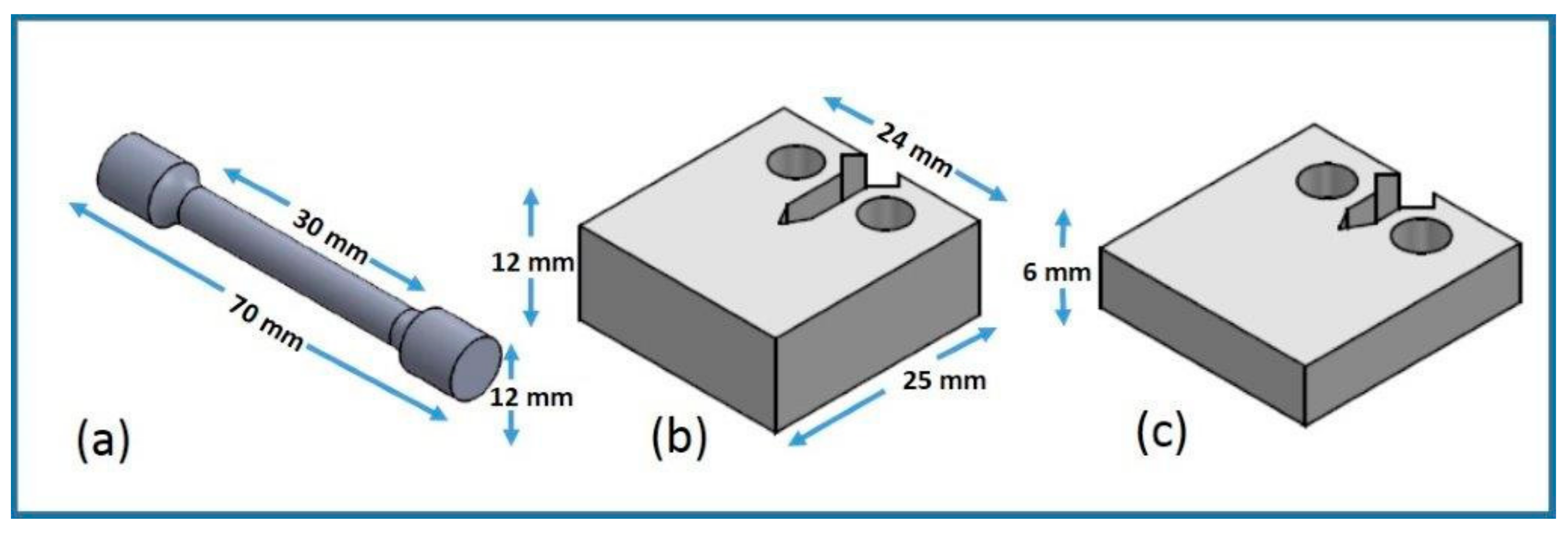
Figure 1.
Optical Microscopy (OM) microstructure of AlSi10Mg (orientation 0°, 45° and 90°) samples: (a–c) at 50× magnification post stress relief.
Figure 1.
Optical Microscopy (OM) microstructure of AlSi10Mg (orientation 0°, 45° and 90°) samples: (a–c) at 50× magnification post stress relief.
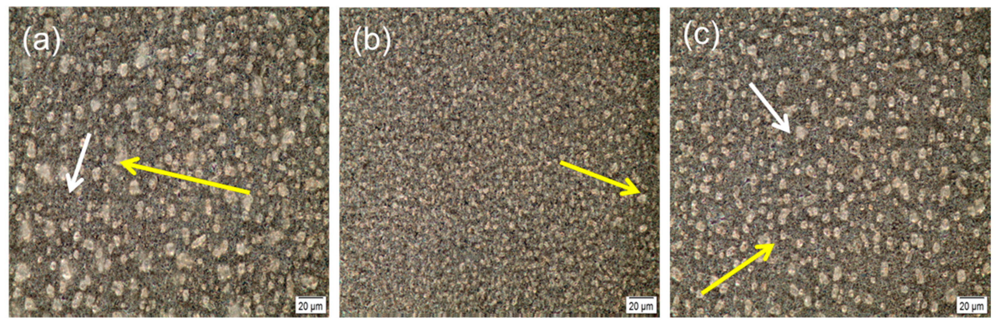
Figure 2.
EBSD of AlSi10Mg samples at the Energy Dispersive Spectroscopy (EDS layer image, orientation A (a) and (d), orientation B (b) and (e) and orientation C (c) and (f), as-built and post stress relief respectively).
Figure 2.
EBSD of AlSi10Mg samples at the Energy Dispersive Spectroscopy (EDS layer image, orientation A (a) and (d), orientation B (b) and (e) and orientation C (c) and (f), as-built and post stress relief respectively).
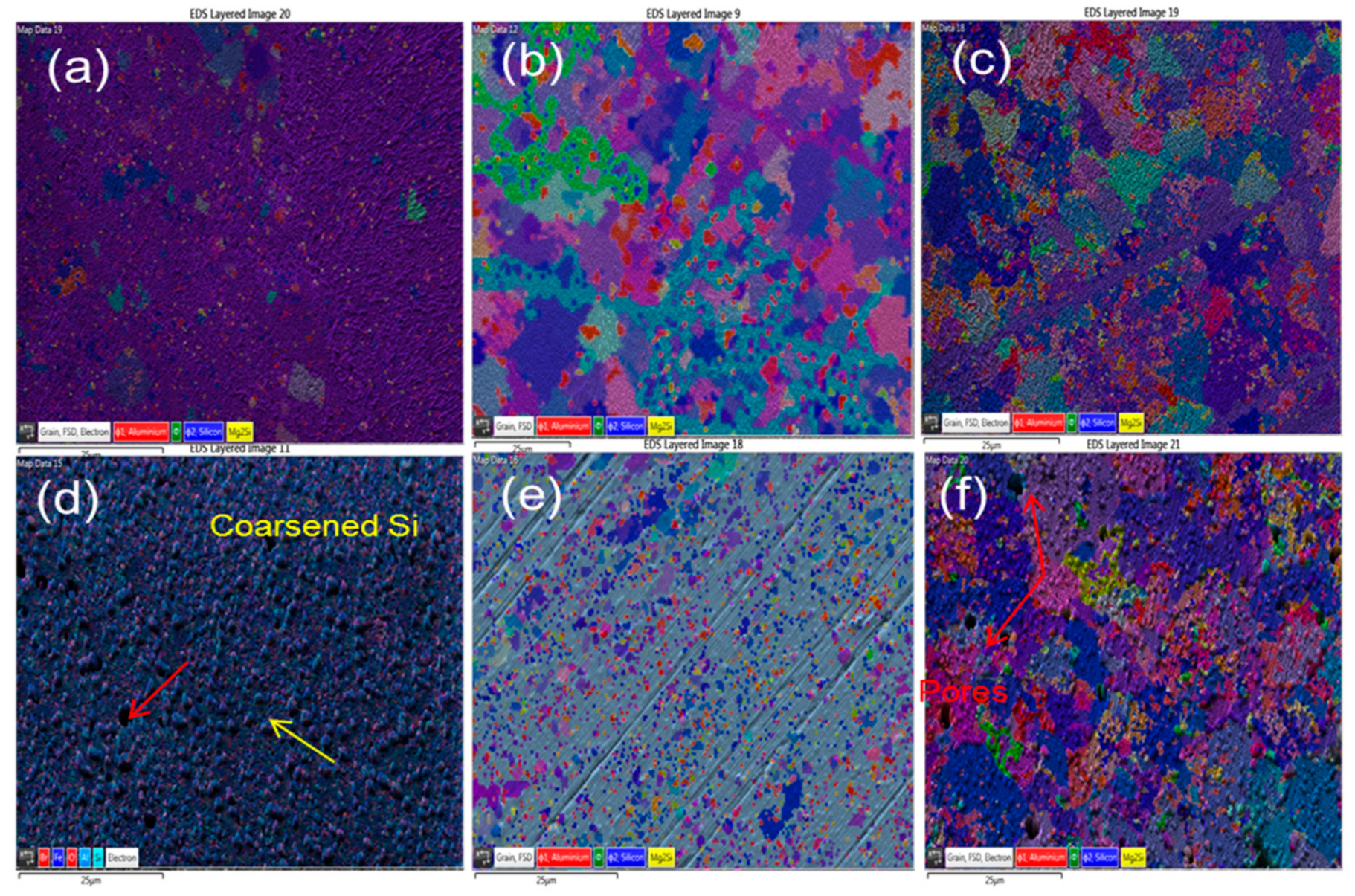
Figure 3.
The illustration of (a) Ultimate Tensile Strength UTS variation and (b) modulus of elasticity for the Selective Laser Melting (SLM) processed AlSi10Mg samples as a function of build direction.
Figure 3.
The illustration of (a) Ultimate Tensile Strength UTS variation and (b) modulus of elasticity for the Selective Laser Melting (SLM) processed AlSi10Mg samples as a function of build direction.

Figure 4.
The illustration of (a) yield strength and (b) elongation for the SLM processed AlSi10Mg samples as a function of build direction.
Figure 4.
The illustration of (a) yield strength and (b) elongation for the SLM processed AlSi10Mg samples as a function of build direction.

Figure 5.
Showing Batch A, B and C (0°; 45° and 90°) samples, (a) tensile strain and (b) extension.
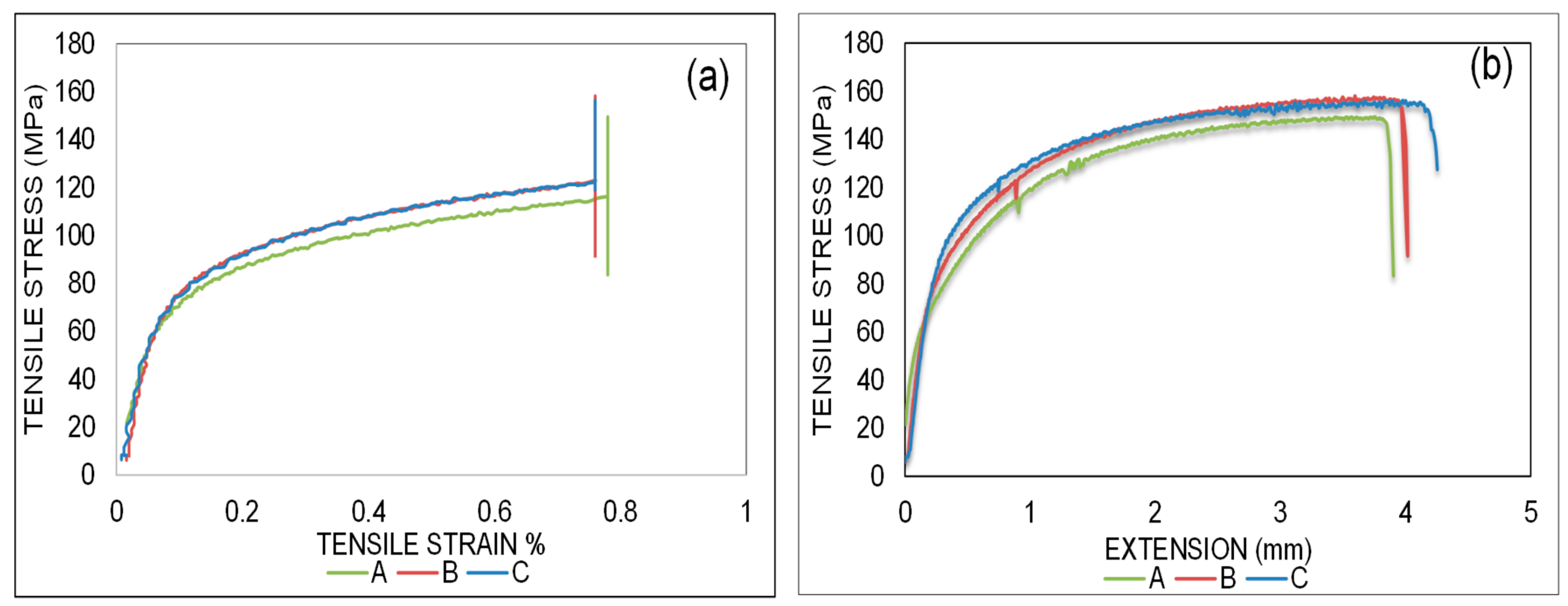
Figure 6.
SEM morphology of SLM produced AlSi10Mg samples, orientation 0° (a) and (d), orientation 45° (b) and (e) and orientation 90° (c) and (f) as-built and post stress relief respectively.
Figure 6.
SEM morphology of SLM produced AlSi10Mg samples, orientation 0° (a) and (d), orientation 45° (b) and (e) and orientation 90° (c) and (f) as-built and post stress relief respectively.

Figure 7.
Fracture toughness results of the SLM produced AlSi10Mg samples.
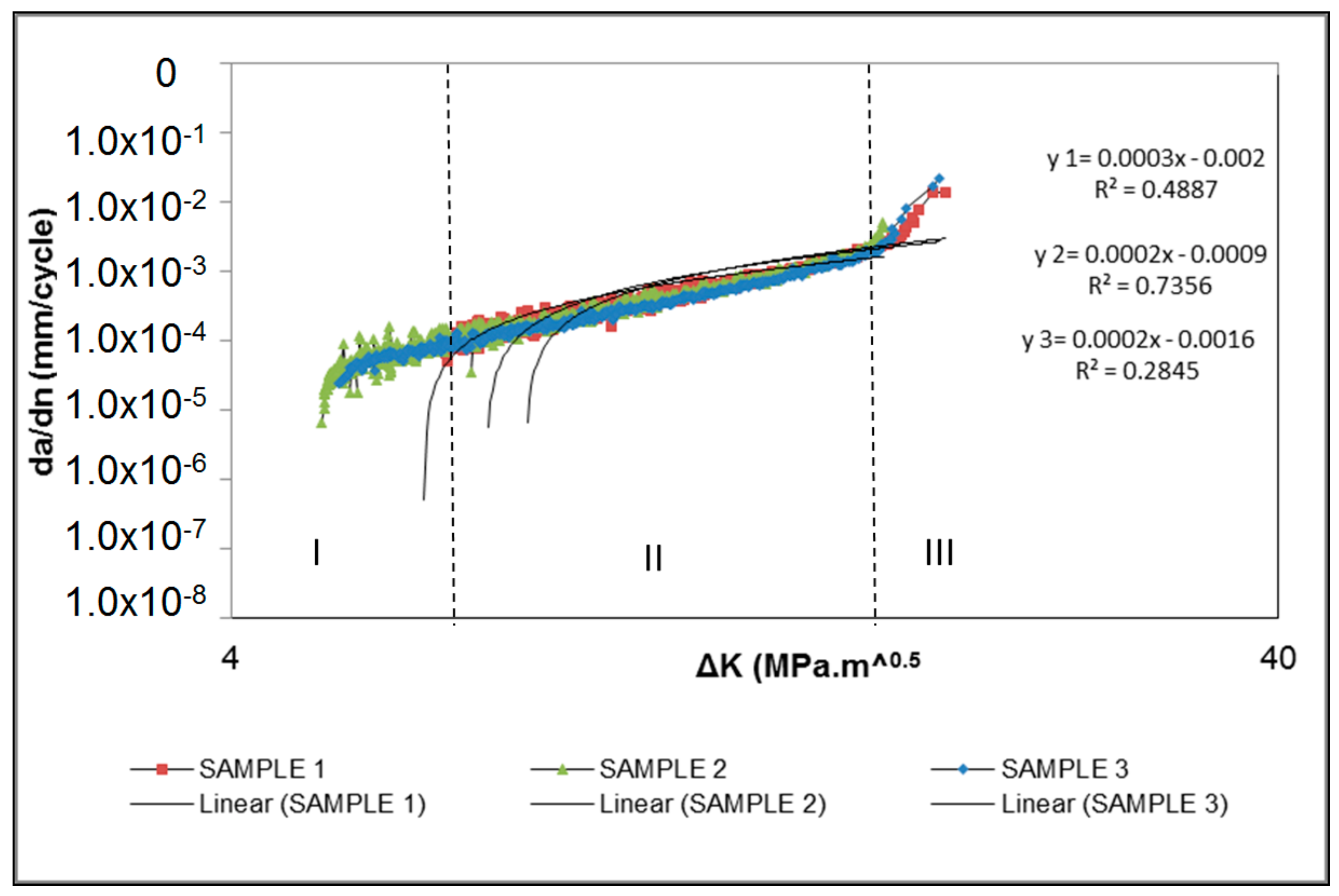
Figure 8.
Illustration of the three fracture toughness samples (a), (b) and (c), SEM images of the SLM produced AlSi10Mg built in 90°.
Figure 8.
Illustration of the three fracture toughness samples (a), (b) and (c), SEM images of the SLM produced AlSi10Mg built in 90°.
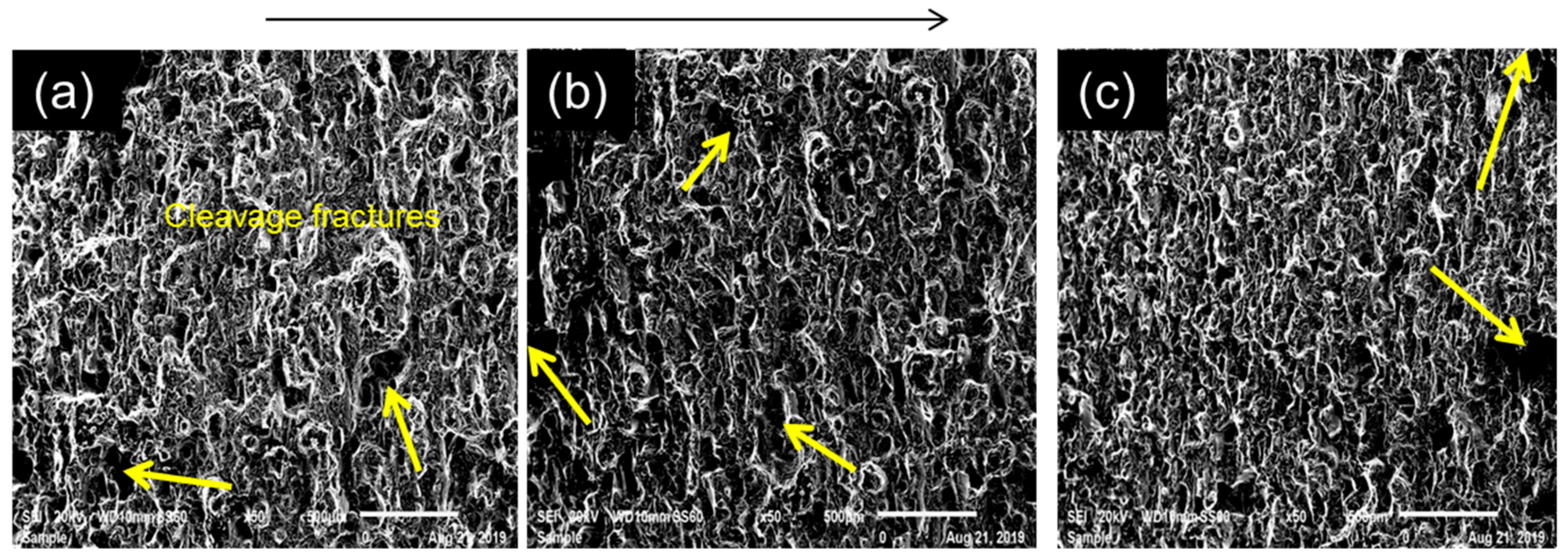
Figure 9.
Crack growth rate results of the SLM produced AlSi10Mg samples.
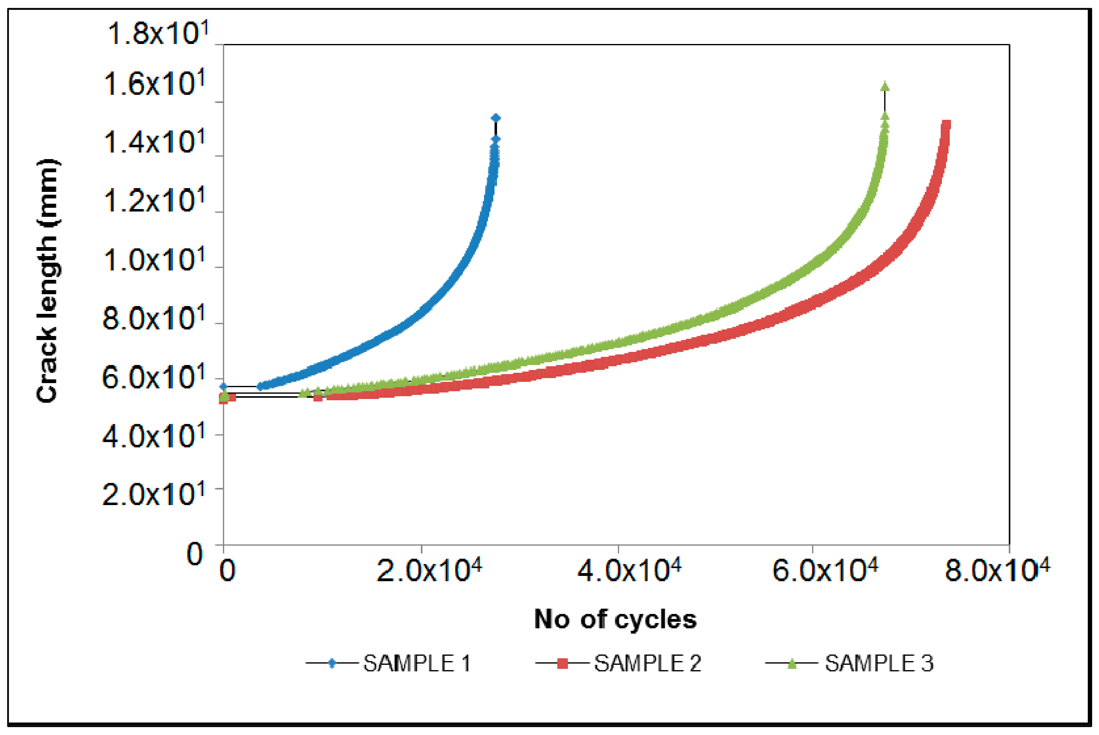
Figure 10.
Crack growth rate SEM results of the SLM produced AlSi10Mg samples where ((a–c) is sample 1, (d–f) is sample 2 and (g–i) is sample 3).
Figure 10.
Crack growth rate SEM results of the SLM produced AlSi10Mg samples where ((a–c) is sample 1, (d–f) is sample 2 and (g–i) is sample 3).

Table 1.
Showing the orientation density and porosity levels after stress relieve.
| Orientation | Density (g/cm3) | Porosity (%) | Relative Density (%) |
|---|---|---|---|
| A (0°) | 2.61 ± 0.025 | 2.67 ± 0.92 | 97.33 ± 0.92 |
| B (45°) | 2.60 ± 0.023 | 3.19 ± 0.86 | 96.81 ± 0.86 |
| C (90°) | 2.58 ± 0.027 | 3.82 ± 1.00 | 96.18 ± 1.00 |
Table 2.
Build orientation hardness results after stress relief.
| Orientation | HV |
|---|---|
| A (0°) | 43.91 ± 2.44 |
| B (45°) | 47.32 ± 3.35 |
| C (90°) | 47.14 ± 4.16 |
Table 3.
Showing as built and stress relieved Electron Backscatter Diffraction (EBSD) phase fraction.
Table 3.
Showing as built and stress relieved Electron Backscatter Diffraction (EBSD) phase fraction.
| AS-BUILT | ||||
|---|---|---|---|---|
| Orientation | EBSD Phase Fraction (%) | |||
| Al | Si | Mg2Si | Zero solution | |
| A (0°) | 2.02 | 8.52 | 1.04 | 88.42 |
| B (45°) | 8.80 | 54.17 | 1.19 | 35.84 |
| C (90°) | 11.48 | 37.23 | 3.47 | 47.82 |
| STRESS RELIEVED | ||||
| Orientation | EBSD Phase Fraction (%) | |||
| Al | Si | Mg2Si | Zero solution | |
| A (0°) | 8.13 | 29.13 | 3.20 | 59.54 |
| B (45°) | 3.09 | 10.15 | 1.67 | 85.09 |
| C (90°) | 11.56 | 37.49 | 2.57 | 48.38 |
© 2019 by the authors. Licensee MDPI, Basel, Switzerland. This article is an open access article distributed under the terms and conditions of the Creative Commons Attribution (CC BY) license (http://creativecommons.org/licenses/by/4.0/).
Share and Cite
MDPI and ACS Style
Mfusi, B.J.; Mathe, N.R.; Tshabalala, L.C.; Popoola, P.A. The Effect of Stress Relief on the Mechanical and Fatigue Properties of Additively Manufactured AlSi10Mg Parts. Metals 2019, 9, 1216. https://doi.org/10.3390/met9111216
AMA Style
Mfusi BJ, Mathe NR, Tshabalala LC, Popoola PA. The Effect of Stress Relief on the Mechanical and Fatigue Properties of Additively Manufactured AlSi10Mg Parts. Metals. 2019; 9(11):1216. https://doi.org/10.3390/met9111216
Chicago/Turabian StyleMfusi, Busisiwe J., Ntombizodwa R. Mathe, Lerato C. Tshabalala, and Patricia AI. Popoola. 2019. "The Effect of Stress Relief on the Mechanical and Fatigue Properties of Additively Manufactured AlSi10Mg Parts" Metals 9, no. 11: 1216. https://doi.org/10.3390/met9111216
Note that from the first issue of 2016, this journal uses article numbers instead of page numbers. See further details here.