Influence of Carbide Morphology on the Deformation and Fracture Mechanisms of Spheroidized 14CrMoR Steel

1
School of Materials Science and Engineering, Beihang University, Beijing 100083, China
2
China Special Equipment Inspection and Research Institute, Beijing 100013, China
*
Author to whom correspondence should be addressed.
Metals 2019, 9(11), 1221; https://doi.org/10.3390/met9111221
Submission received: 10 October 2019
/
Revised: 10 November 2019
/
Accepted: 11 November 2019
/
Published: 13 November 2019
Abstract
:The influence of carbide morphology on the deformation and fracture mechanisms of as-received and complete spheroidization 14Cr1MoR steel was investigated using an in situ scanning electron microscope (SEM) under tension testing. During spheroidization damage, the carbide morphology changed from the original lamellar cementite present in pearlite to granular M23C6 carbide, which was concentrated along the ferrite grain boundaries. The yield strength and tensile strength of 14Cr1MoR steel decreased with the increasing degree of spheroidization damage. In situ SEM observations revealed that the deformation and crack initiation started from the ferrite matrix in both as-received and completely spheroidization-damaged 14Cr1MoR steel samples. However, the extension of slip bands and crack propagation behavior of both samples were different during the in situ tensile process, which could be ascribed to the difference in carbide morphology. In the as-received 14Cr1MoR steel sample, hard and brittle lamellar pearlite resulted in high-strength ferrite/ pearlite boundaries, which inhibited the movement of slip bands. With further deformation, the concentration of stress at the crack tip resulted in the emergence and propagation of cracks along the ferrite/pearlite boundaries. In the case of the completely spheroidized 14Cr1MoR steel sample, slip bands bypassed the grain boundary carbide and continuously expanded into the neighboring ferrite grain. In addition, micro-voids and fractures of grain boundary carbides were observed due to the large stress concentration at the front of crack tip. Then, the micro-voids connected with the main crack to complete the crack propagation behavior. The morphological changes of carbides deteriorated the mechanical properties and altered the fracture behavior of 14Cr1MoR steel. It is worth noting that the fracture surface morphology of 14Cr1MoR steel changed from a combination of lamellar fracture and dimpled morphology to a completely dimples-dominated morphology after spheroidization.
1. Introduction
14Cr1MoR steel is a low-alloy Cr–Mo steel with a ferrite and pearlite microstructure that is widely used in variety of applications, such as thermal power equipment, nuclear power equipment, and large-scale conversion equipment for petrochemicals due to its excellent strength, superior oxidation resistance, and low hydrogen embrittlement at elevated temperatures [1]. Moreover, the demand for 14Cr1MoR steel has surged recently due to the rapid development of the petrochemical industry in China.
However, under prolonged exposure to high-temperature service environments, pearlite colonies disintegrate, and the microstructure transforms from lamellar cementite (Fe3C) to spherical carbide, causing aggregation at ferrite boundaries [2,3,4,5]. The schematic diagram of pearlite spheroidization is presented in Figure 1. With the increase in service time, more spherical carbides are distributed along ferrite boundaries and coarsened, resulting in the degradation of mechanical properties [4,5,6,7,8,9,10,11]. Moreover, pearlite spheroidization damage severely affects the performance of the material during service.
One should note that pearlite spheroidization is an inevitable process that occurs in 14Cr1MoR steel during long-term operation at high temperatures. Therefore, a large number of studies focused on the microstructural evolution and property alterations of pearlite spheroidization damage [2,3,4,5,6,7,8,9,10,11]. However, long-term service operations change the initial ferrite/pearlite microstructure into a ferrite/carbide microstructure, which significantly influences the deformation and fracture mechanisms. Unfortunately, few investigations concerning this have been reported thus far.
Compared with conventional static testing, in situ microstructural observations during mechanical testing provide a better understanding of the mechanical behavior, and present real-time images regarding the inherent deformation and fracture processes. Therefore, in situ scanning electron microscopy has been widely carried out to understand the overall deformation and fracture behaviors of different materials [12,13,14,15,16,17,18,19].
In this study, in situ tensile testing was utilized to demonstrate real-time morphological changes and investigate the influence of carbide morphology on the fracture process and the deformation behavior of 14CrMoR steel after spheroidization damage. The spheroidization-damaged 14Cr1MoR steel samples were obtained by accelerating the spheroidization experiment. SEM and transmission electron microscopy (TEM) were carried out to analyze the morphological evolution of carbides during the spheroidization process.
2. Materials and Experimental Procedures
2.1. Materials and Accelerated Spheroidization Experiment
The specimens were obtained from a 14Cr1MoR plate; the chemical composition is shown in Table 1. The chemical composition was confirmed with an ARL-4460 direct-reading spectrometer (Thermo Fisher, Woburn, MA, USA). The normal working temperature of 14Cr1MoR was below 550 °C. Therefore, a longer time was required to achieve a completely spheroidized microstructure due to the low spheroidization rate in the given temperature range. Lee et al. [20] reported that pearlite spheroidization occurs below AC1 temperature, which corresponded to the initiation of the austenite phase, and the spheroidization rate increased with the increase in temperature. In this study, 14Cr1MoR steel was aged at 680 °C to accelerate the pearlite spheroidization. One should note that the given temperature was lower than the AC1 temperature and higher than the normal working temperature. The maximum aging time was set at 100 h. After thermal aging, the 14Cr1MoR steel samples were water-quenched to avoid phase transformation. After polishing and etching in 4% Nital solution, the microstructure was observed using TESCAN VEGA 3 SEM (Tescan, South Moravia, Czech Republic) and FEI TecnaiGF30 TEM (Thermo Fisher, Woburn, MA, USA). The Instron 8801 testing machine (Instron, Shanghai, China).was used to assess the tensile properties with a test standard of GB/T228.1-2010. The geometry of the sample is shown in Figure 2. The strain rate was set as 1 mm/min. The HRC hardness was tested using an HR5-150 Rockwell hardness tester (Jiu bin, Shanghai, China).
2.2. In Situ Tensile Characterization
The in situ tensile test was performed with a micro-static–dynamic testing machine (Shimadzu, Tokyo, Japan) and a scanning electron microscope, which was dedicated for in situ SEM observations. The maximum load of the testing machine was 1000 N. The geometry and dimensions of the specimens are shown in Figure 3. To observe the crack initiation during the test, a U-shaped notch with a depth of 0.2 mm was designed by wire-cutting one side of each specimen, as shown in Figure 3. Then, the samples were polished and etched in 4% Nital solution for microstructure observations. The deformation rate was set at 0.001 mm/s.
3. Results and Discussion
3.1. The Morphological Evolution of Carbides During Spheroidization
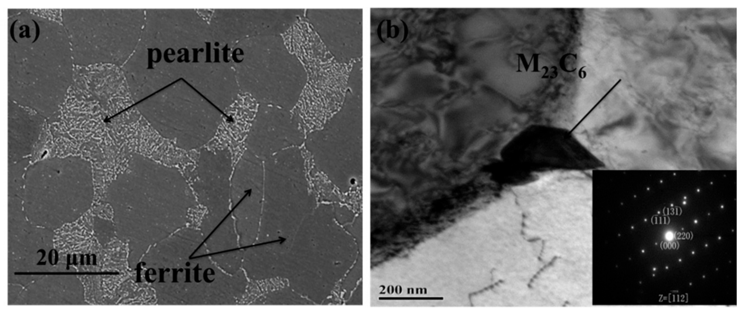
As shown in Figure 4a, the as-received 14Cr1MoR steel mainly consisted of ferrite, pearlite, and a small number of particles which were distributed along the grain boundaries of ferrite. TEM images and a selected area electron diffraction (SAED) pattern of particles that were distributed along grain boundaries are presented in Figure 4b. The SAED pattern confirmed that the distributed particles belonged to the M23C6 phase, which is a stable carbide phase. One should note that a small amount of M23C6 phase can improve the hydrogen corrosion resistance at high temperatures.
Figure 5 shows the SEM images of 14Cr1MoR steel aged at 680 °C for 22, 40, 70, and 100 h. Compared with Figure 4a, the evolution of the pearlite was readily observed during aging. Initially, the lamellar carbides started to disperse in the pearlite. Then, the size and number of carbide particles, which were distributed along the ferrite grain boundaries, increased with increasing aging time. However, the morphology of the pearlite was clearly observed, as shown in Figure 5a,b. With the increase in aging time, the lamellar carbides completely changed to a granular morphology and a higher number of distributed particles was observed along the grain boundaries, as shown in Figure 5c. After aging for 100 h, the pearlite morphology disappeared, and large particles concentrated along the grain boundaries were observed, as seen in Figure 5d. The TEM images and SAED patterns of the precipitated particles are given in Figure 6, confirming that the precipitated particles belonged to the M23C6 carbide phase.
The driving force for pearlite spheroidization is generally believed to be associated with the reduction in curvature between the pearlite and ferrite matrices [21]. Pearlite possesses a complex layered structure, which is alternately overlapped by thin layers of ferrite and cementite. However, an engineered pearlite lamellar structure is never perfect, and various types of defects, such as kinks, striations, holes, fissures, and terminations, always exist in the cementite lamellae, which are enriched with lamellar fault regions of higher curvature. These regions of greater curvature possess a higher amount of chemical potential [22].
According to the Gibbs–Thomson equation, the carbon concentration equilibrium in ferrite with a small curvature radius is higher than in ferrite with a larger curvature radius [18]. During isothermal aging, the carbide atoms diffused from the higher chemical potential and high curvature lamellar fault sites to adjacent ferrite through interfaces, sub-boundaries, and dislocations. Therefore, the initial pearlite regions were gradually dissolved. Due to the fast grain boundary diffusion, the particles located at the grain boundaries and triple junctions possessed a size advantage following the Ostwald ripening process. As a result, the spheroidized carbide particles precipitated along the ferrite grain boundaries and coarsened with increasing aging time [20]. The major mechanism of isothermal spheroidization can be described as the atomic diffusion from high curvature fault sites to neighboring interfaces, as explained by “fault migration theory” [23]. Overall, the microstructure evolution results confirmed that the pearlite spheroidization was not an instantaneous process and gradually occurred with increasing aging time due to the migration of carbide atoms.
3.2. The Evolution of Mechanical Properties and in situ Tensile Characterization
Figure 7 shows the mechanical properties of 14Cr1MoR steel samples after different aging times at 680 °C. Room-temperature tensile characterizations of 14Cr1MoR steel samples were carried out after aging at 680 °C for different lengths of time, as shown in Figure 7a. The results show that the yield strength and tensile strength decreased with an increase in the degree of spheroidization damage (i.e., increased aging time). The HRC hardness of spheroidization-damaged 14Cr1MoR steel samples exhibited a similar trend to the yield strength and tensile strength trends.
Figure 8 presents the SEM images of as-received 14Cr1MoR steel during in situ tensile testing under different loads, where the double-headed arrow indicates the loading direction. Figure 8a shows the microstructure of the as-received 14Cr1MoR steel sample near the U-shape notch, which mainly consisted of ferrite and pearlite. A crack defect was found at the center of the notch, which may have been produced by wire-cutting or after grinding and polishing, as shown in Figure 8a. The microstructure of the as-received 14Cr1MoR steel did not exhibit any obvious change under the tensile load of 500 N, as shown in Figure 8b. However, a crack initiated at the notch when the tensile load was increased to 550 N. The initiated crack was located in the ferrite matrix and occurred at 45° with the loading direction. However, the defect crack did not exhibit any obvious change, as shown in Figure 8c. When the load was further increased to 590 N, the initiated crack was widened and stretched forward, as shown in Figure 8d. In addition, another crack appeared above the defect crack, which was named initial crack 2. Then, both initiated cracks continuously extended with increasing load. In the front of the initiated crack, slip bands were observed in the ferrite grains. The density of slip bands was extremely high, and they stopped at the ferrite/pearlite interface, as shown in Figure 8e–g. In addition to the emergence of slip bands, the deformation of the ferrite matrix also occurred under tensile load, as shown by the microstructural evolution of Ferrite 1 in Figure 8f–h. When the load exceeded the maximum force and then decreased to 720 N, the initial crack became the main crack and propagated rapidly.
Figure 9 presents the microstructural evolution of 14Cr1MoR steel after complete spheroidization damage under different tensile loads. The original microstructure is shown in Figure 9a, where the ferrite grains were approximately equiaxed and the carbides were mainly distributed along the ferrite grain boundaries. When a tensile load of 490 N was applied, a crack source region was observed near the notch, which was also presented in the ferrite matrix (Figure 9b). When the tensile load increased to 600 N, two new crack source regions appeared at the notch. To distinguish these source regions, the three crack source regions were named Source region 1, Source region 2, and Source region 3. In front of crack source regions, the slip bands appeared in several ferrite grains without any distinct morphological transformation. Moreover, the parallel slip bands indicated the activation of only one slip system, as shown in Figure 9c. With greater tensile load, the morphology of the crack source regions, i.e., Source region 2 and Source region 3, exhibited significant changes, such as crack widening and stretching. However, in front of the tip of the crack, the slip bands remained coarser and uninterrupted by ferrite grain boundaries. The slip bands bypassed the grain boundaries of the granular carbides and continued to expand into the neighboring ferrite grains, as shown in Figure 9c–f. When the load exceeded the maximum force and then decreased to 660 N, the crack present in Source region 2 became the main crack and rapidly propagated until failure.
Microstructural evolution comparison revealed that the completely spheroidized 14Cr1MoR steel sample exhibited the same plastic deformation behavior as the as-received 14Cr1MoR steel sample. One should note that the second phase plays a critical role in dual-phase alloy system. The initial plastic deformation always occurs in the softer phase and is usually confined to the local area, depending on volume fraction, shape, and distribution of the harder phase [20]. In the as-received 14Cr1MoR steel sample, the microstructure was composed of ferrite and lamellar pearlite, whereas the shape of the carbides transformed from the original lamellar structure to granular carbides, or even disappeared in the completely spheroidized 14Cr1MoR steel sample. The microstructure of the completely spheroidized 14Cr1MoR steel sample was mainly composed of ferrite and granular carbides, which were distributed along the ferrite grain boundaries. As the ferrite matrix was relatively easier to deform than the pearlite and granular carbides, the deformation and crack initiation originated from the ferrite matrix. One should note that the ferrite phase with a body-centered cubic (BCC) structure possesses sufficient slip systems. Therefore, with the increase in tensile load, the slip became the major deformation mode for the ferrite and straight slip bands originated from the ferrite (softer) phase.
Moreover, the initially observed slip bands were aligned in only one direction, indicating the activation of one dominant slip system. With continued deformation, the fine slip bands became coarser and multiple slip bands were observed in front of the initial crack, indicating the dominance of the cross-slip deformation mechanism. In addition to the appearance of the slip bands within grains, the morphology of the ferrite grains also changed during deformation. Though the ferrite grains were gradually elongated, the pearlite and granular carbides kept their morphology until the stress reached a threshold limit. A large concentration of stress at the softer/harder phase interface caused by deformation in the softer phase may cause coordinating deformation to occur in the harder phase [24,25,26].
However, during the tensile test, the slip bands stopped at the ferrite/pearlite interface of the as-received 14Cr1MoR steel (Figure 8f), whereas the slip bands were not interrupted at the ferrite boundaries in the completely spheroidized 14Cr1MoR steel sample, as shown in Figure 9c. The hard and brittle lamellar pearlite resulted in a high-strength ferrite/pearlite interface, which inhibited the movement of the slip bands. These results were in good agreement with previous reports [27].
Figure 10 presents the crack tip morphology of the as-received 14Cr1MoR steel sample during crack propagation. As mentioned earlier, coordinating deformation may occur in a softer/harder phase interface due to deformation of the softer phase, which may cause a large concentration of stress at the softer/harder phase interface [20,21,22]. Therefore, at the front of crack tip, when the stress concentration exceeded the interfacial bonding strength of the ferrite/pearlite boundary, the cracks were generated at the ferrite/pearlite boundary and converged with the main crack, resulting in crack propagation along the ferrite/pearlite boundary. Figure 11 presents the microstructure of the crack tip during the crack propagation of the aging sample. As shown in Figure 11a,b, several micro-voids were readily observed at the front of crack tip, which could be attributed to the severe slip band coarsening. Moreover, some of the carbides distributed along the grain boundaries in the completely spheroidized 14Cr1MoR steel sample moved with the migration of the grain boundary and contributed to the fracture during the in situ tension test, as illustrated by arrows in Figure 11c,d. It is worth nothing that micro-cracks were formed by micro-voids and boundary carbide fractures, which connected with the main crack and completed the crack propagation.
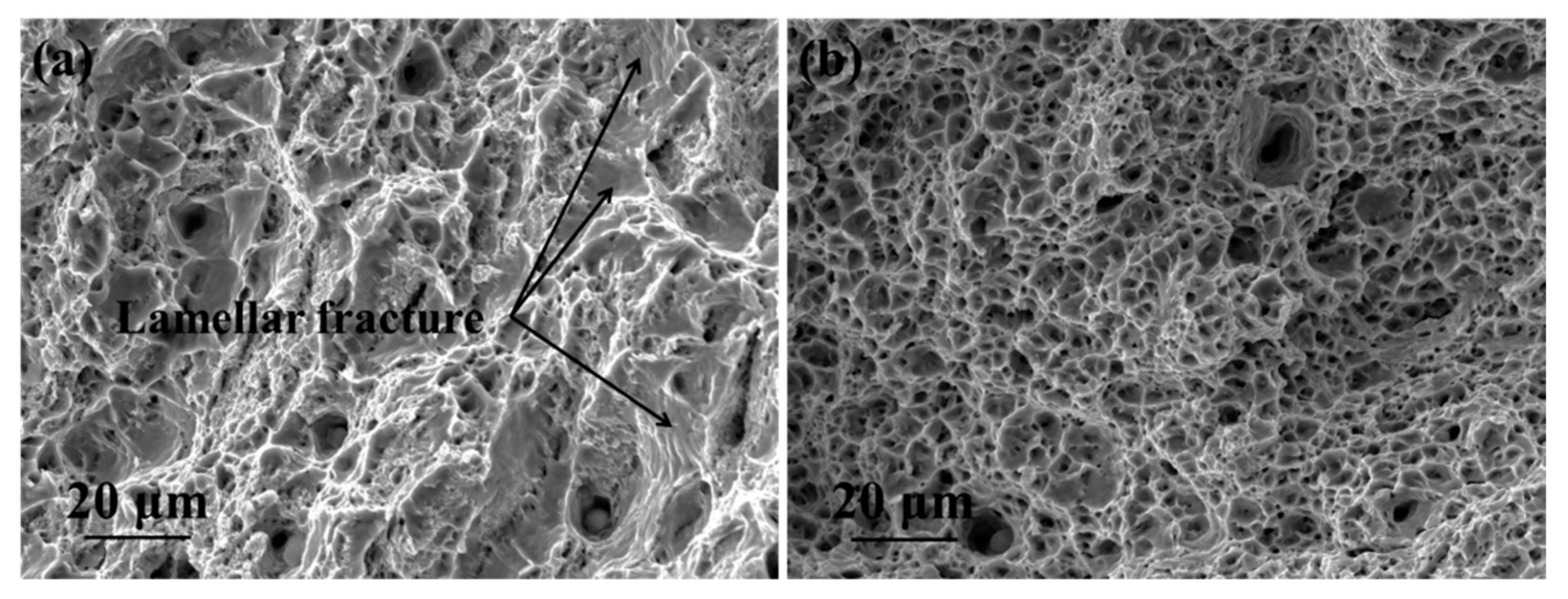
The fractured morphologies of the as-received and completely spheroidized 14Cr1MoR steel samples are presented in Figure 12. The as-received sample exhibited dimples and wavy regions of lamellar fracture, as shown in Figure 12a, where the dimples originated from micro-voids that coalesced in the ferritic regions. The lamellar fracture was exhibited in the pearlite region, which indicated the nucleation and propagation of the crack along the junction of the different pearlite colonies. The lamellar fracture in the pearlite regions was responsible for the higher tensile strength of the as-received 14Cr1MoR steel. As shown in Figure 12b, the fracture surface of the completely spheroidization-damaged 14Cr1MoR steel was occupied by dimples, which could be ascribed to the failure mode involving coalescence of the micro-voids (Figure 11).
In situ microstructural observations of the deformation and fracture behaviors of as-received and completely spheroidized 14Cr1MoR steel samples demonstrated that the carbide morphology controlled the movement of slip bands, crack propagation behavior, and the fracture mode during tensile testing. The hard and brittle lamellar carbide that was present in the pearlite phase changed to a spheroidal structure or even disappeared during spheroidization. The spherical carbide rendered lower resistance to the dislocation movement than lamellar pearlite. Moreover, the severe deformation of the ferrite matrix and the fracture of the spherical carbide introduced micro-voids, which facilitated the crack propagation in the completely spheroidized 14Cr1MoR steel sample. Therefore, the morphological evolution of carbide during the spheroidization damage process deteriorated the mechanical properties and altered the fracture morphology from a lamellar fracture /dimpled morphology as seen in the as-received 14Cr1MoR steel to a dimple-dominant morphology as seen in the completely spheroidization-damaged 14Cr1MoR steel.
4. Conclusions
In summary, we utilized in situ scanning electron microscopy to unveil the microstructural changes during tensile loading and understand the deformation and fracture behaviors of as-received and completely spheroidized 14Cr1MoR steel. The following conclusions can be drawn from the current work:
- (1)
- Under the tensile load, the deformation and crack initiation started in the ferrite matrix in both the as-received and completely spheroidized 14Cr1MoR steel samples.
- (2)
- With the increase in strain, the high-strength ferrite/pearlite interface inhibited the movement of slip bands. The concentration of stress at the crack tip cracked the ferrite/pearlite interface and facilitated crack propagation along the ferrite/pearlite interface.
- (3)
- In the completely spheroidized 14Cr1MoR steel, the slip bands were no longer interrupted by ferrite at the grain boundary, implying that the slip bands bypassed the grain boundary carbides and traversed through the ferrite boundaries. Therefore, the dislocations were more easily produced in ferrite than pearlite. Moreover, micro-cracks were formed by micro-void coalescence and grain boundary carbide fractures, which connected with the main crack and completed the crack propagation.
- (4)
- The carbide morphology of the completely spheroidized 14Cr1MoR steel facilitated the dislocation and propagation of the cracks, which led to inferior mechanical properties. The fracture morphology of the as-received 14Cr1MoR steel changed from a lamellar/dimpled morphology to a dimple-dominant morphology after spheroidization damage.
Author Contributions
Formal analysis, S.W.; funding acquisition, L.C.; writing—original draft, S.W.; writing—review and editing, Z.Z.
Funding
This research was funded by the China Special Equipment Inspection and Research Institute (Grant No. KH54020901) and China Petroleum and Chemical Corporation (Grant No. 315098).
Conflicts of Interest
The authors declare no conflict of interest.
References
- Al-Abbasi, F.M. Micromechanical modeling of ferrite-pearlite steels. Mater. Sci. Eng. A 2010, 527, 6904–6916. [Google Scholar] [CrossRef]
- Bhadeshia, H.K.D.H. Steels for bearings. Prog. Mater. Sci. 2012, 57, 268–435. [Google Scholar] [CrossRef]
- Yasniy, O.; Vuherer, T.; Yasniy, V.; Sobchak, A.; Sorochak, A. Mechanical behaviour of material of thermal power plant steam superheater collector after exploitation. Eng. Fail. Anal. 2013, 27, 262–271. [Google Scholar] [CrossRef]
- Ostash, O.P.; Kondyr, A.I.; Vol’demarov, O.V.; Hladysh, P.V.; Kurechko, M.V. Structural microdamageability of steels of the steam pipelines of thermal power plants. Mater. Sci. 2009, 45, 340–349. [Google Scholar] [CrossRef]
- Dzioba, I. Failure assessment analysis of pipelines for heat and power generating plants according to the SINTAP procedures. Int. J. Press. Vessel. Pip. 2005, 82, 787–796. [Google Scholar] [CrossRef]
- Qu, Z.; Mcmahon, C.J. The Effects of Tempering Reactions on Temper Embrittlement of Alloy Steels. Metall. Trans. A 1983, 14, 1101–1108. [Google Scholar] [CrossRef]
- Xu, H.; Huang, X.K.; Yang, Z.; Pan, J.T. Property changes of 12Cr1MoV with 10CrMo910 main steam piping after long-term high-temperature service. Eng. Fail. Anal. 2003, 10, 245–250. [Google Scholar] [CrossRef]
- Bose, S.C.; Reddy, K.S.; Reddy, G.J.; Singh, K.; Sarma, D.S. Effect of service-simulated aging on the microstructure and properties of casing casting steel (1CrMoV) vis-à-vis, remnant life assessment. Metall. Mater. Trans. A 2003, 34, 1265–1274. [Google Scholar] [CrossRef]
- Romaniv, O.N.; Tkach, A.N.; Dzioba, I.R.; Simin’kovich, V.N.; Islamov, A.A. Effect of long-term thermomechanical treatment on the crack resistance of 12Kh1MF steel. Mater. Sci. 1989, 25, 202–208. [Google Scholar] [CrossRef]
- Berezina, T.G.; Borodina, é.R.; Ashikhmina, L.A. Effect of brief heating on resistance to fracture of steel 12Kh1MF. Met. Sci. Heat Treat. 1975, 3, 188–190. [Google Scholar] [CrossRef]
- Zhao, Q.H.; Jiang, B.; Wang, J.M. Pearlite spheroidization mechanism and lifetime prediction of 12Cr1MoV steel used in power plant. In Proceedings of the 4th Annual International Conference on Material Science and Engineering (ICMSE 2016), Guangzhou, China, 17–19 June 2016; Atlantis Press: Paris, France, 2016; pp. 195–201. [Google Scholar]
- Haque, M.A.; Saif, M.T.A. In-situ tensile testing of nano-scale specimens in SEM and TEM. Exp. Mech. 2002, 42, 123–128. [Google Scholar] [CrossRef]
- Liu, W.; Long, L.; Ma, Y.; Wu, L. Microstructure evolution and mechanical properties of Mg/Al diffusion bonded joints. J. Alloys Compd. 2015, 643, 34–39. [Google Scholar] [CrossRef]
- Chris, R.; Benjamin, B.; Arvin, A. In Situ Mechanical Testing Techniques for Real-Time Materials Deformation Characterization. JOM 2016, 68, 136–142. [Google Scholar]
- Mušálek, R.; Kovářík, O.; Matějíček, J. In-situ observation of crack propagation in thermally sprayed coatings. Surf. Coat. Technol. 2010, 205, 1807–1811. [Google Scholar] [CrossRef]
- Agarwal, H.; Gokhale, A.M.; Graham, S.; Horstemeyer, M.F. Void growth in 6061-aluminum alloy under triaxials stress state. Mater. Sci. Eng. A 2003, 341, 35–42. [Google Scholar] [CrossRef]
- Xu, Z.; Ma, Z.; Yan, J.; Zhang, Y.; Zhang, X. Strain field and fracture behavior of Ti/Al dissimilar alloy joint under in situ tensile test. Acta Metall. Sin. 2016, 52, 1403–1412. [Google Scholar]
- Hémery, S.; Nait-Ali, A.; Villechaise, P. Combination of in-situ SEM tensile test and FFT-based crystal elasticity simulations of Ti-6Al-4V for an improved description of the onset of plastic slip. Mech. Mater. 2017, 109, 1–10. [Google Scholar] [CrossRef]
- Wang, W.; Liu, T.; Cao, X.; Lu, Y.; Shoji, T. In-situ observation on twin boundary evolution and crack initiation behavior during tensile test on 316L austenitic stainless steel. Mater. Charact. 2017, 132, 169–174. [Google Scholar] [CrossRef]
- Lee, Y.W.; Son, Y.I.; Lee, S.J. Microstructure and mechanical properties of spheroidized D6AC steel. Mater. Sci. Eng. A 2013, 585, 94–99. [Google Scholar] [CrossRef]
- Li, L.; Yang, W.; Sun, Z. Microstructure Evolution of a Pearlitic Steel during Hot Deformation of Undercooled Austenite and Subsequent Annealing. Metall. Mater. Trans. A 2008, 39, 624–635. [Google Scholar] [CrossRef]
- Yong, L.T.; Kraft, R.W. Mechanisms of Pearlite Spheroidization. Metall. Trans. A 1987, 18, 1403–1414. [Google Scholar]
- Saha, A.; Mondal, D.K.; Maity, J. Effect of cyclic heat treatment on microstructure and mechanical properties of 0.6 wt% carbon steel. Mater. Sci. Eng. A 2010, 527, 4001–4007. [Google Scholar] [CrossRef]
- Guo, E.Y.; Wang, M.Y.; Jing, T.; Chawla, N. Temperature-dependent mechanical properties of an austenitic–ferritic stainless steel studied by in situ, tensile loading in a scanning electron microscope (SEM). Mater. Sci. Eng. A 2013, 580, 159–168. [Google Scholar] [CrossRef]
- Dobrzański, J.; Hernas, A. Cerrelation between phase composition and life-time of 1Cr0.5Mo steels during long-term service at elevated temperatures. J. Mater. Process. Technol. 1995, 53, 101–108. [Google Scholar] [CrossRef]
- Afrouz, A.; Collins, M.J.; Pilkington, R. Microstructural examination of 1Cr-O-5Mo steel during creep. Met. Technol. 1983, 10, 461–463. [Google Scholar] [CrossRef]
- Fan, L. Analysis on the deformation and fracture behavior of carbon steel by in situ tensile test. Int. Miner. Metall. Mater. 2006, 13, 504–507. [Google Scholar]
Figure 1.
The schematic illustration of pearlite spheroidization.

Figure 2.
The geometry and dimensions (in mm) of the tensile specimen.
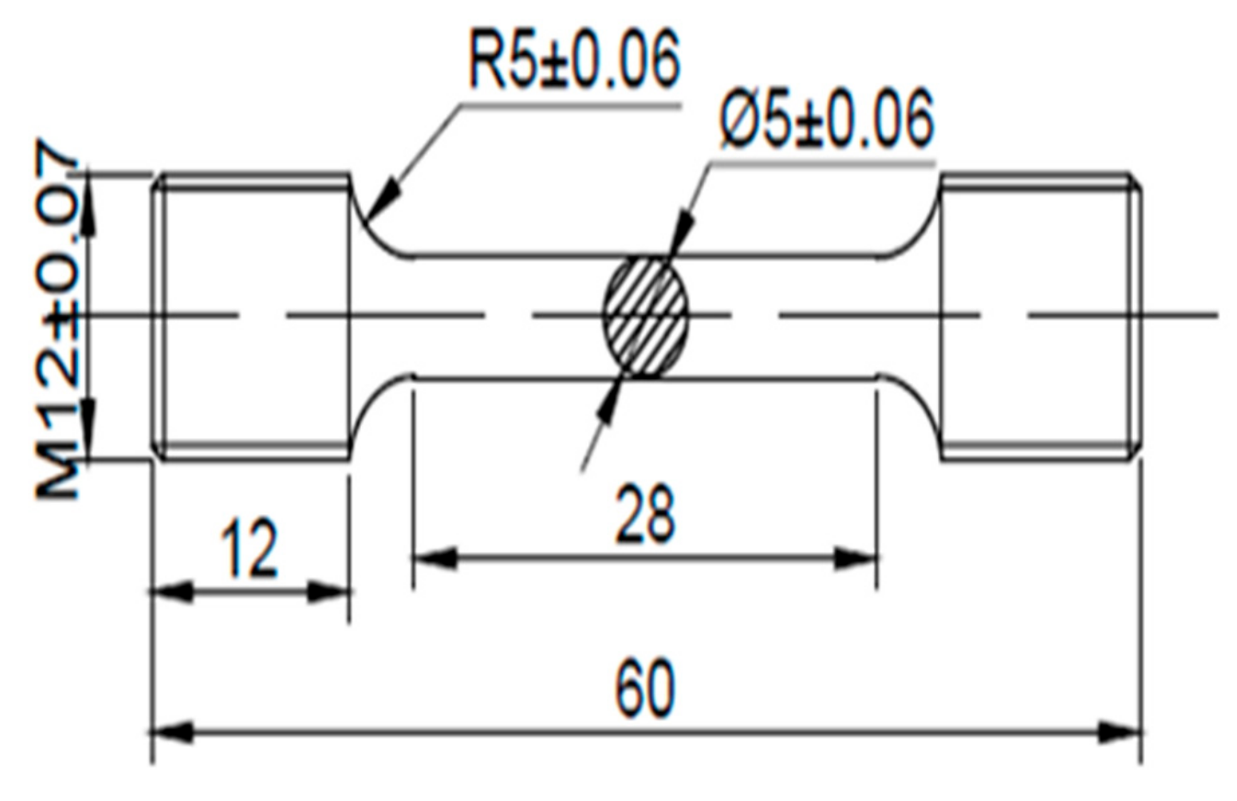
Figure 3.
The geometry and dimensions (in mm) of in situ tensile specimens.
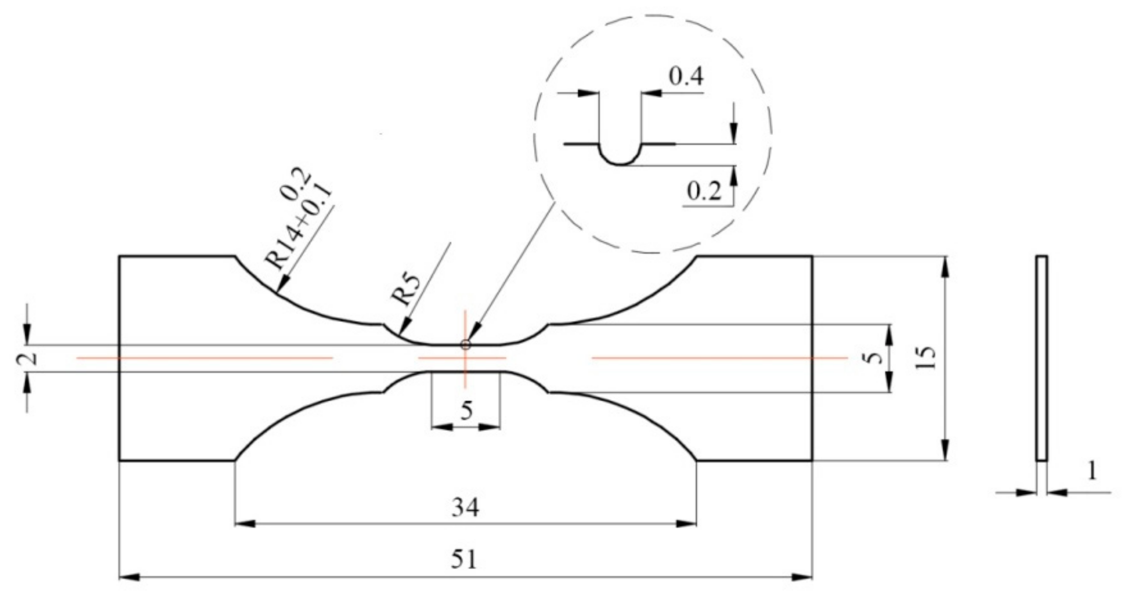
Figure 4.
The microstructure of as-received 14Cr1MoR steel. (a) SEM and (b) TEM images, where the inset in (b) shows the selected area electron diffraction (SAED) pattern of the M23C6 phase.
Figure 4.
The microstructure of as-received 14Cr1MoR steel. (a) SEM and (b) TEM images, where the inset in (b) shows the selected area electron diffraction (SAED) pattern of the M23C6 phase.

Figure 5.
Microstructural evolution of 14Cr1Mo steel aged at 680 °C for (a) 22 h, (b) 40 h, (c) 70 h, and (d) 100 h.
Figure 5.
Microstructural evolution of 14Cr1Mo steel aged at 680 °C for (a) 22 h, (b) 40 h, (c) 70 h, and (d) 100 h.

Figure 6.
TEM images and corresponding SAED patterns of 14Cr1MoR steel aged at 680 °C for 100 h.
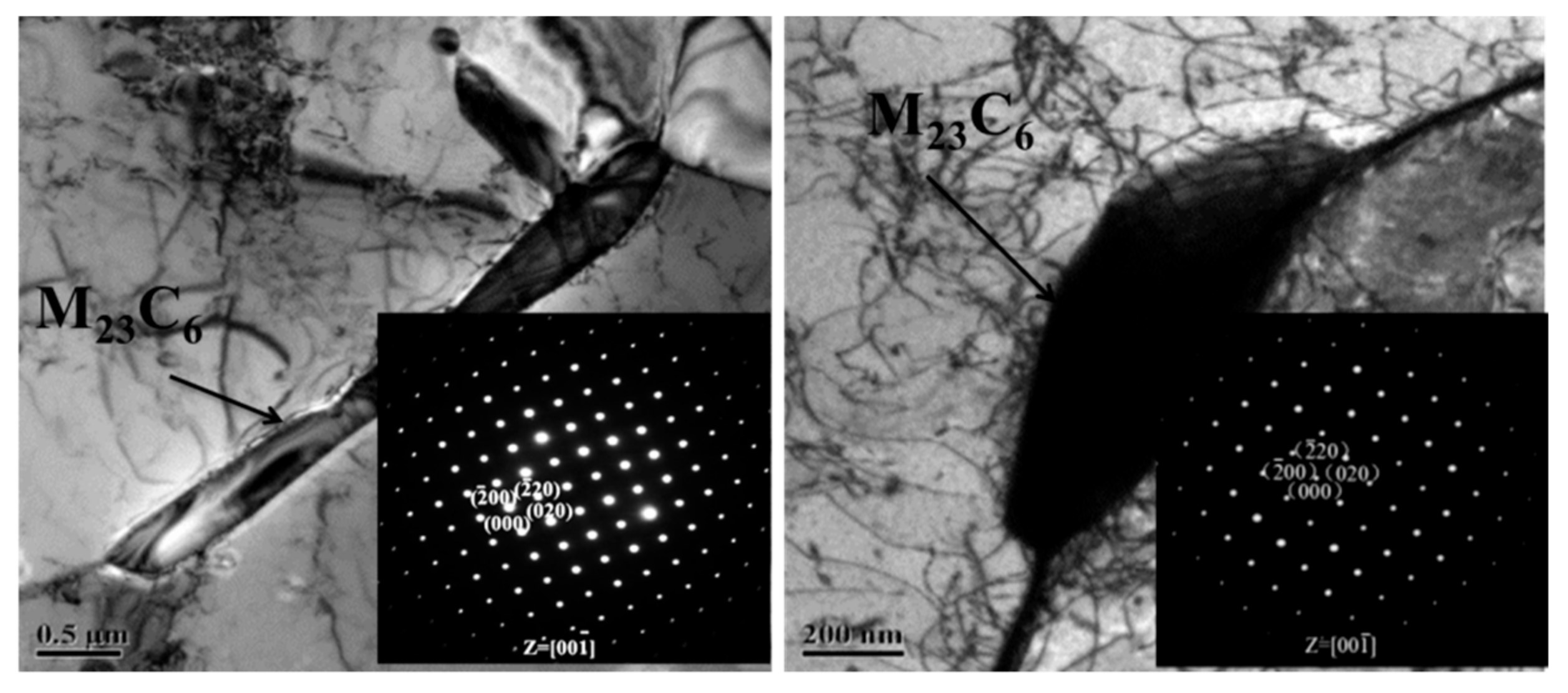
Figure 7.
Mechanical properties of 14Cr1MoR steel samples after different aging times at 680 °C. (a) Load-displacement curves and (b) HRC hardness.
Figure 7.
Mechanical properties of 14Cr1MoR steel samples after different aging times at 680 °C. (a) Load-displacement curves and (b) HRC hardness.
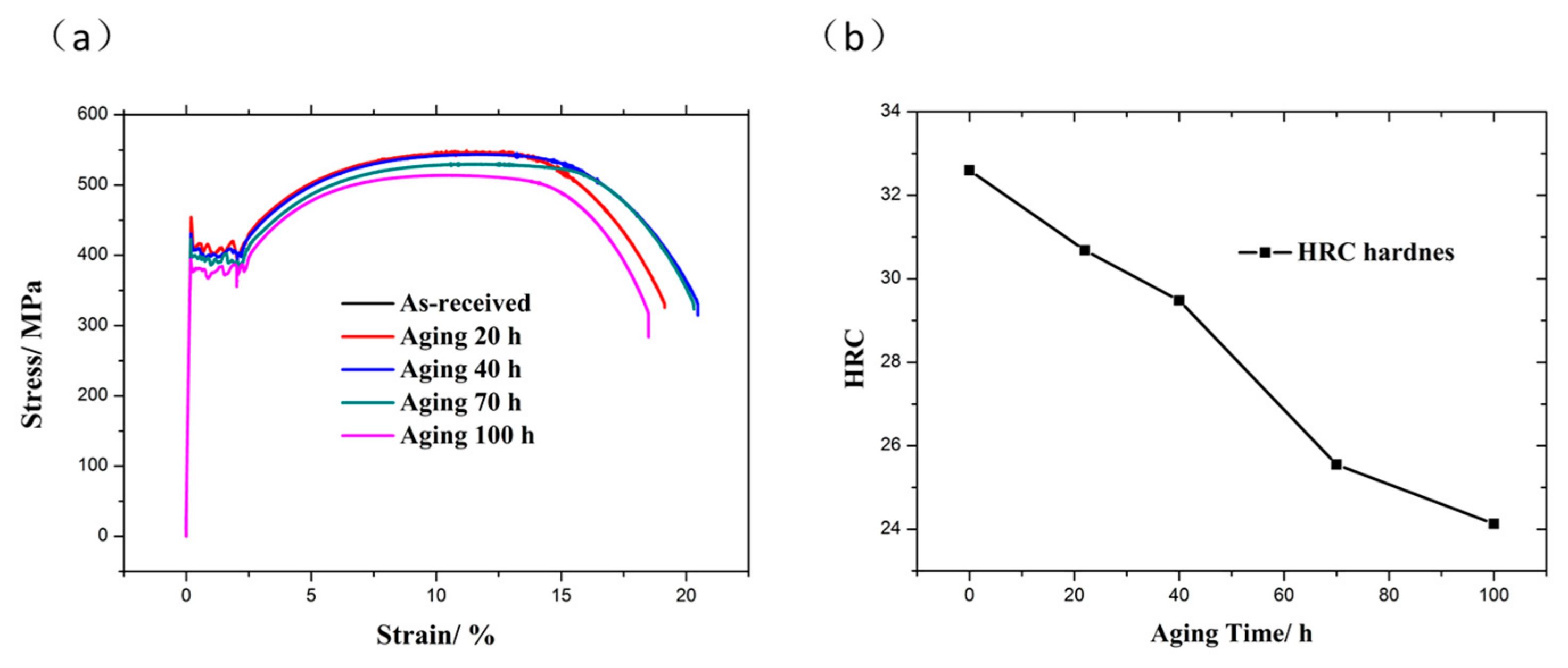
Figure 8.
Microstructural evolution of as-received 14Cr1MoR steel during in situ tensile testing. (a) 0 N, (b) 500 N, (c) 550 N, (d) 590 N, (e) 650 N, (f) 720 N, (g) 730 N, and (h) 720 N.
Figure 8.
Microstructural evolution of as-received 14Cr1MoR steel during in situ tensile testing. (a) 0 N, (b) 500 N, (c) 550 N, (d) 590 N, (e) 650 N, (f) 720 N, (g) 730 N, and (h) 720 N.
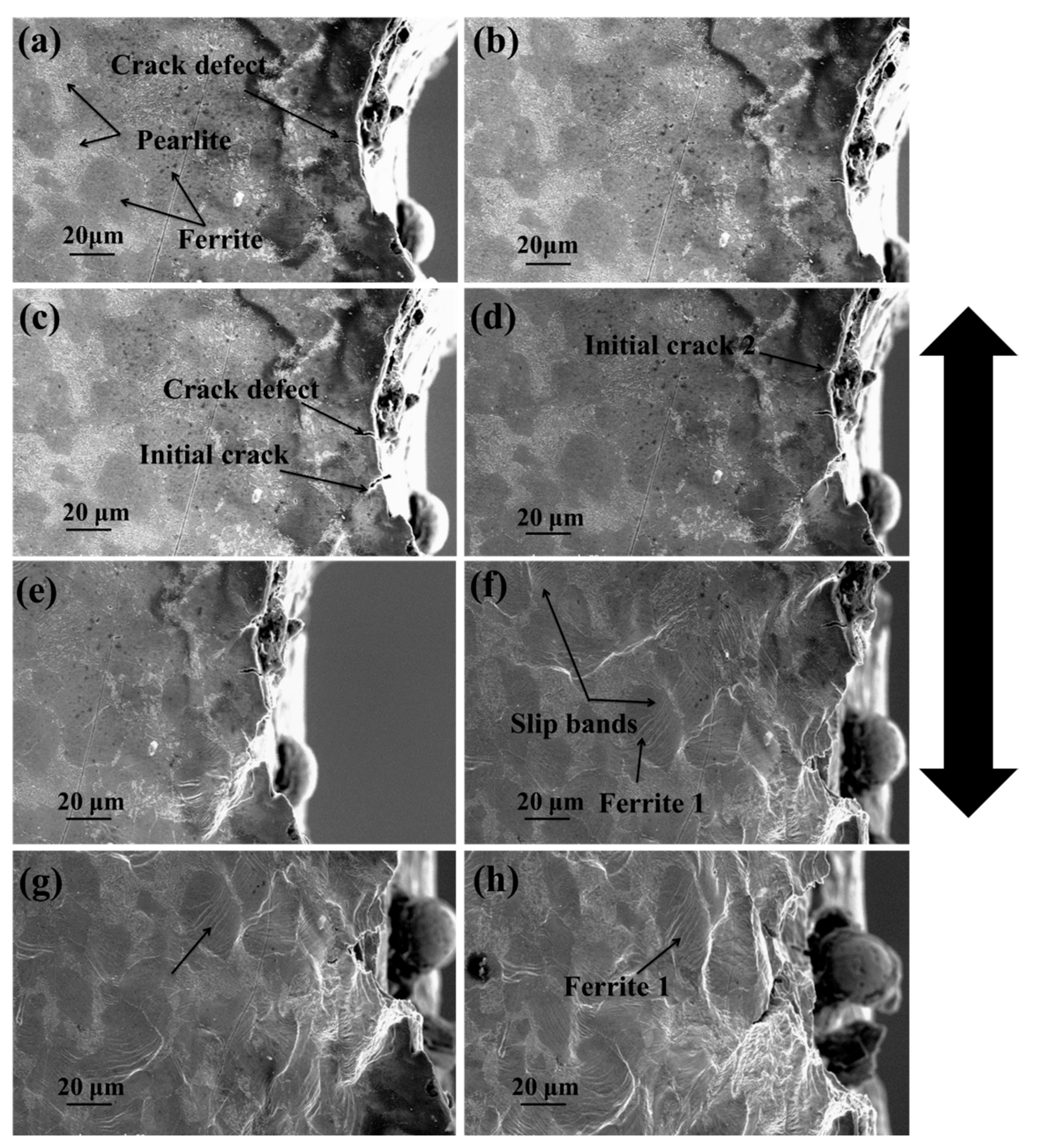
Figure 9.
Microstructural evolution of completely spheroidized 14Cr1MoR steel during in situ tensile testing. (a) 0 N, (b) 490 N, (c) 600 N, (d) 640 N, (e) 680 N, and (f) 660 N.
Figure 9.
Microstructural evolution of completely spheroidized 14Cr1MoR steel during in situ tensile testing. (a) 0 N, (b) 490 N, (c) 600 N, (d) 640 N, (e) 680 N, and (f) 660 N.
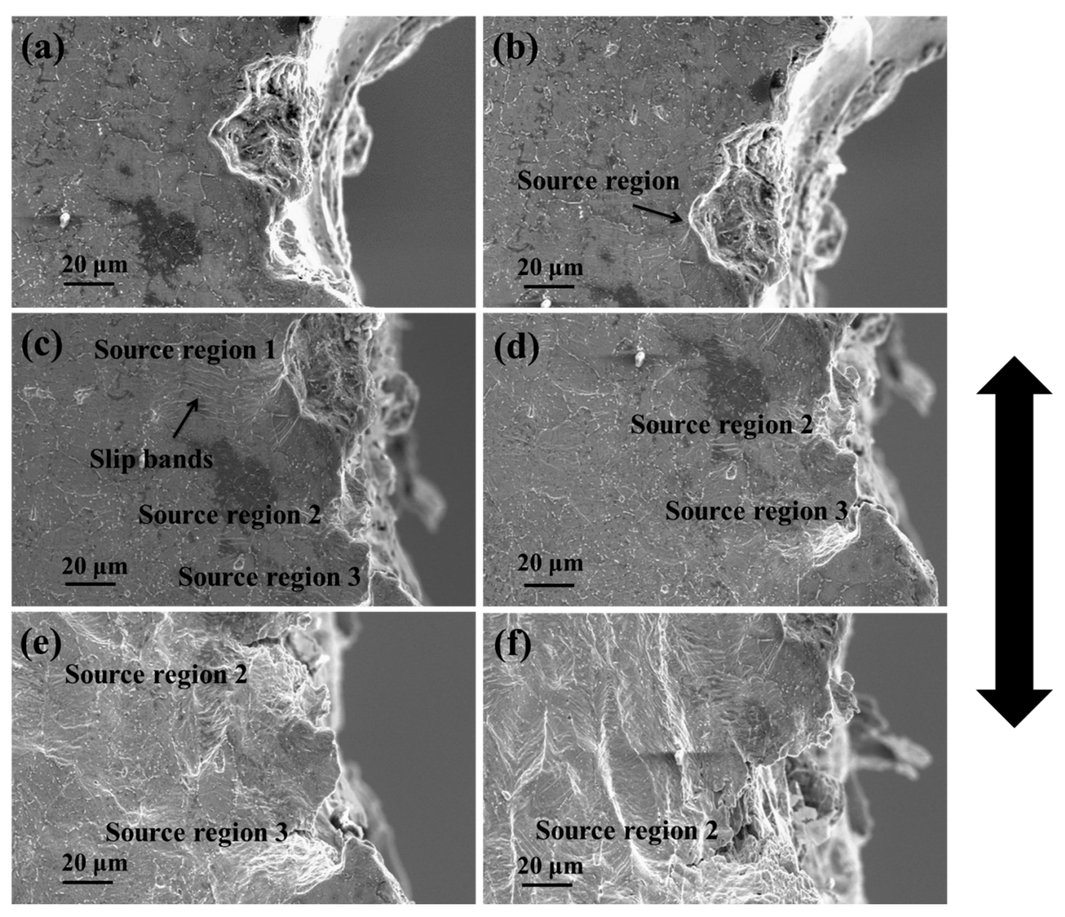
Figure 10.
The morphology of the crack tip in as-received 14Cr1MoR steel during crack propagation.

Figure 11.
The morphology of the crack tip in completely spheroidization-damaged 14Cr1MoR steel during crack propagation. (a) 630 N, (b) 600 N, (c) 580 N, (d) 580 N.
Figure 11.
The morphology of the crack tip in completely spheroidization-damaged 14Cr1MoR steel during crack propagation. (a) 630 N, (b) 600 N, (c) 580 N, (d) 580 N.
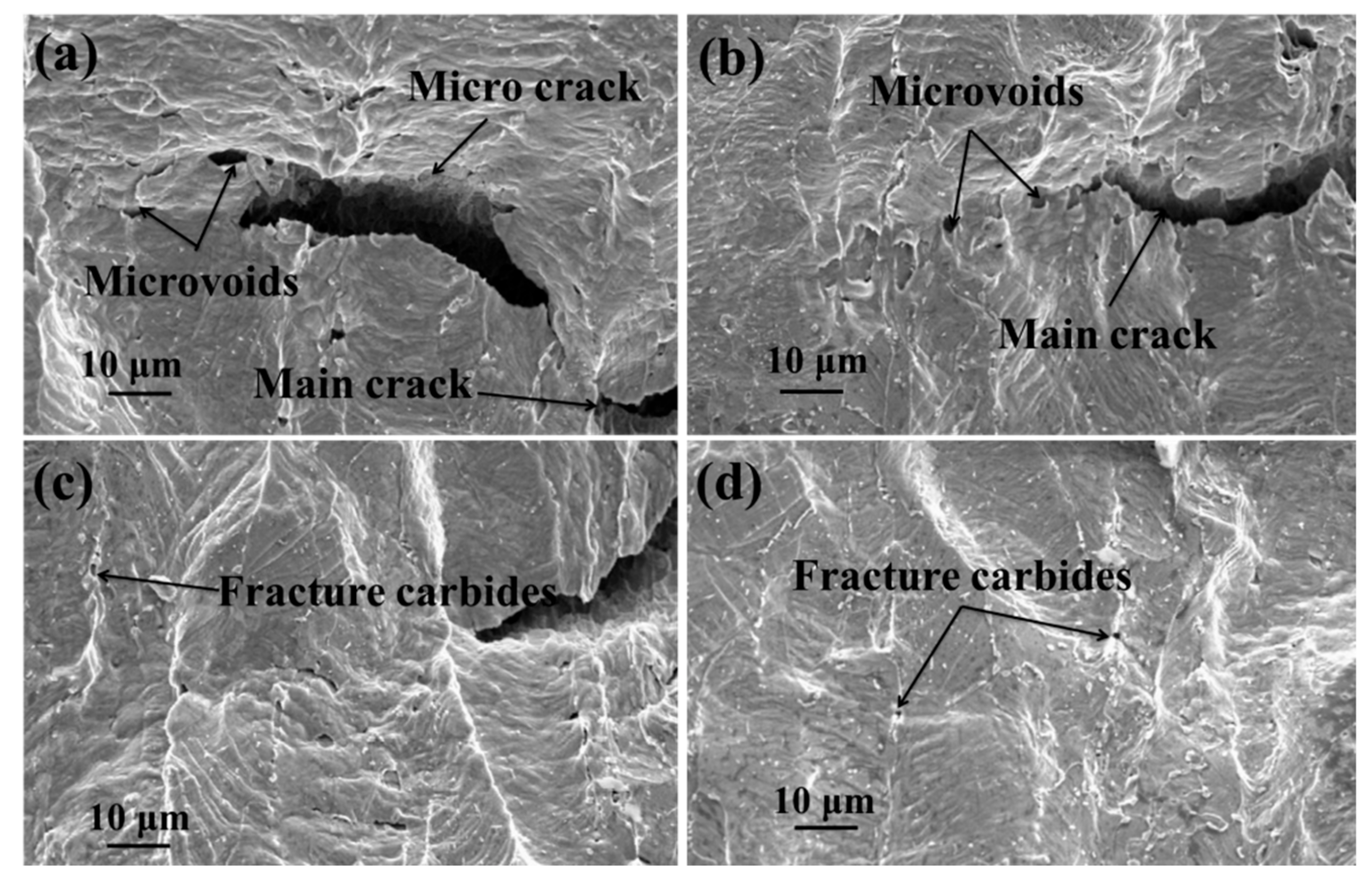
Figure 12.
The fracture morphology of in situ tensile specimens. (a) As-received 14Cr1MoR steel; (b) completely spheroidized 14Cr1MoR steel.
Figure 12.
The fracture morphology of in situ tensile specimens. (a) As-received 14Cr1MoR steel; (b) completely spheroidized 14Cr1MoR steel.


Table 1.
Chemical composition (wt%) of 14Cr1MoR steel.
| Elements | C | Ni | Mn | Cr | Mo | Fe |
|---|---|---|---|---|---|---|
| Composition (wt%) | 0.16 | 0.022 | 0.48 | 1.2 | 0.47 | Bal. |
© 2019 by the authors. Licensee MDPI, Basel, Switzerland. This article is an open access article distributed under the terms and conditions of the Creative Commons Attribution (CC BY) license (http://creativecommons.org/licenses/by/4.0/).
Share and Cite
MDPI and ACS Style
Wang, S.; Cao, L.; Zhang, Z. Influence of Carbide Morphology on the Deformation and Fracture Mechanisms of Spheroidized 14CrMoR Steel. Metals 2019, 9, 1221. https://doi.org/10.3390/met9111221
AMA Style
Wang S, Cao L, Zhang Z. Influence of Carbide Morphology on the Deformation and Fracture Mechanisms of Spheroidized 14CrMoR Steel. Metals. 2019; 9(11):1221. https://doi.org/10.3390/met9111221
Chicago/Turabian StyleWang, Shifu, Luowei Cao, and Zheng Zhang. 2019. "Influence of Carbide Morphology on the Deformation and Fracture Mechanisms of Spheroidized 14CrMoR Steel" Metals 9, no. 11: 1221. https://doi.org/10.3390/met9111221
Note that from the first issue of 2016, this journal uses article numbers instead of page numbers. See further details here.