Effect of Deposition Parameters on Microstructure of the Ti-Mg Immiscible Alloy Thin Film Deposited by Multi-Arc Ion Plating


1
School of Materials Science and Engineering, Tongji University, 4800 Caoan Road, Shanghai 201804, China
2
Shanghai Key Laboratory for R&D and Application of Metallic Functional Materials, Shanghai 201804, China
3
School of Mechanical and Mining Engineering, The University of Queensland, Brisbane, QLD 4072, Australia
4
College of Automotive, Tongji University, Shanghai 201804, China
5
College of Mechatronics and Control Engineering, Shenzhen University, Shenzhen 518060, China
*
Author to whom correspondence should be addressed.
Metals 2019, 9(11), 1229; https://doi.org/10.3390/met9111229
Submission received: 21 October 2019
/
Revised: 8 November 2019
/
Accepted: 14 November 2019
/
Published: 17 November 2019
Abstract
:Ti-Mg immiscible alloy thin films were prepared using a multi-arc ion plating technique with various deposition parameters. The surface and cross-section morphologies, crystal structures, and chemical compositions of the Ti-Mg films were investigated by scanning electron microscopy (SEM), X-ray diffraction (XRD), and transmission electron microscopy (TEM). The influence of the substrate negative bias voltage and Ar gas pressure on the microstructure of the Ti-Mg films was systematically studied. Mg atoms were incorporated into the Ti lattice to form an FCC immiscible supersaturated solid solution phase in the thin film. Microparticles were observed on the film surface, and the number of microparticles could be significantly reduced by decreasing the substrate bias voltage and increasing the Ar gas pressure. The appropriate substrate bias voltage and Ar gas pressure increased the deposition rate. The TEM results indicated that columnar, nanolayer, and equiaxed nanocrystals were present in the thin films. Ti and Mg fluctuations were still evident in the nanoscale structures.
1. Introduction
Compared with traditional metallic biomaterials (such as Co-Cr alloy and 316L stainless steel), Ti-Mg binary alloys have become promising biomedical materials for orthopedic implant applications due to various properties [1]. Ti-Mg alloys exhibit low Young’s modulus compared to traditional Ti-based materials, and the mechanical compatibilities of Ti-Mg alloys help prevent the stress-shielding effect and facilitate the formation of bone-to-implant bonds [2]. Ti and Mg exhibit high biocompatibilities with the human body, and Mg is a metallic element that occurs naturally in bone tissue [3,4]. In addition, the Ti-Mg alloy is also a biodegradable implant material, and the Mg in Ti-Mg alloys is biodegradable in the human body. The degradation process generates numerous pores, which facilitate the growth of cells and improve the bonding between the bones and implant materials [5,6,7,8].
It is well known that Ti-Mg binary alloys are thermodynamically immiscible due to their positive enthalpy of mixing [9]. In the equilibrium phase diagram, the solubility of Ti in Mg is only 0.1 at. % (500 °C), and that of Mg in Ti is 0.3 at. % under the same conditions [10,11]. In addition, the boiling point of Mg (1380 K) is much lower than the melting point of Ti (1941 K). Therefore, Ti-Mg alloys cannot be synthesized by conventional casting methods. Several techniques, including severe plastic deformation [12,13], infiltration [6], and sintering [5,14], have been developed to fabricate Ti-Mg composite materials using blended Ti and Mg powders. However, large Mg particles are always present in these ex-situ Ti-Mg composite materials, which results in extremely high Mg degradation rate in physiological conditions. A large quantity of hydrogen gas is generated during this rapid degradation process, which delays the healing of fractured bone tissue. Previous studies demonstrated that non-equilibrium techniques, such as mechanical alloying [15,16] and physical vapor deposition (PVD) [17], can greatly increase the solid solubility of Mg in Ti, forming metastable Ti-Mg supersaturated solid solutions with face-centered cubic (FCC) or body-centered cubic (BCC) structures [18,19]. High-temperature annealing of the supersaturated solid solution leads to its decomposition, forming equilibrium Ti and Mg phases [15,20]. The crystalline Mg phase in this in situ Ti-Mg composite material is fine and homogenous, which is favorable for the reduction of the Mg degradation rate. Compared with powder materials, Ti-Mg thin film materials are more suitable for large scale applications. Studies on the synthesis of Ti-Mg immiscible alloy thin films by magnetron sputtering deposition [21,22] or plasma immersion ion implantation [23] have been reported. However, few studies on the preparation of Ti-Mg alloy thin films using the multi-arc ion plating (MAIP) process have been reported. MAIP is an advanced ion plating technology for depositing thin-film materials. The metal material is vaporized and ionized from a cathode target source by the arc discharge generated between the target source and anode substrate. MAIP is a widely used PVD technology in the industry for the preparation of thin films of various alloys due to its high efficiency, high density, and good adhesion [24,25].
In the MAIP deposition process, many deposition parameters ultimately determine the microstructures, compositions, and performances of the as-deposited thin films. The substrate negative bias voltage and Ar partial pressure are two important parameters in the MAIP deposition process. In this work, Ti-Mg immiscible alloy thin films were deposited by the MAIP process. A Ti-Mg supersaturated solid solution thin film with an FCC structure was formed. The effects of the deposition parameters, including the substrate negative bias, coating vacuum, on the microstructural evolution of the Ti-Mg immiscible alloy thin films were investigated.
2. Experimental Part
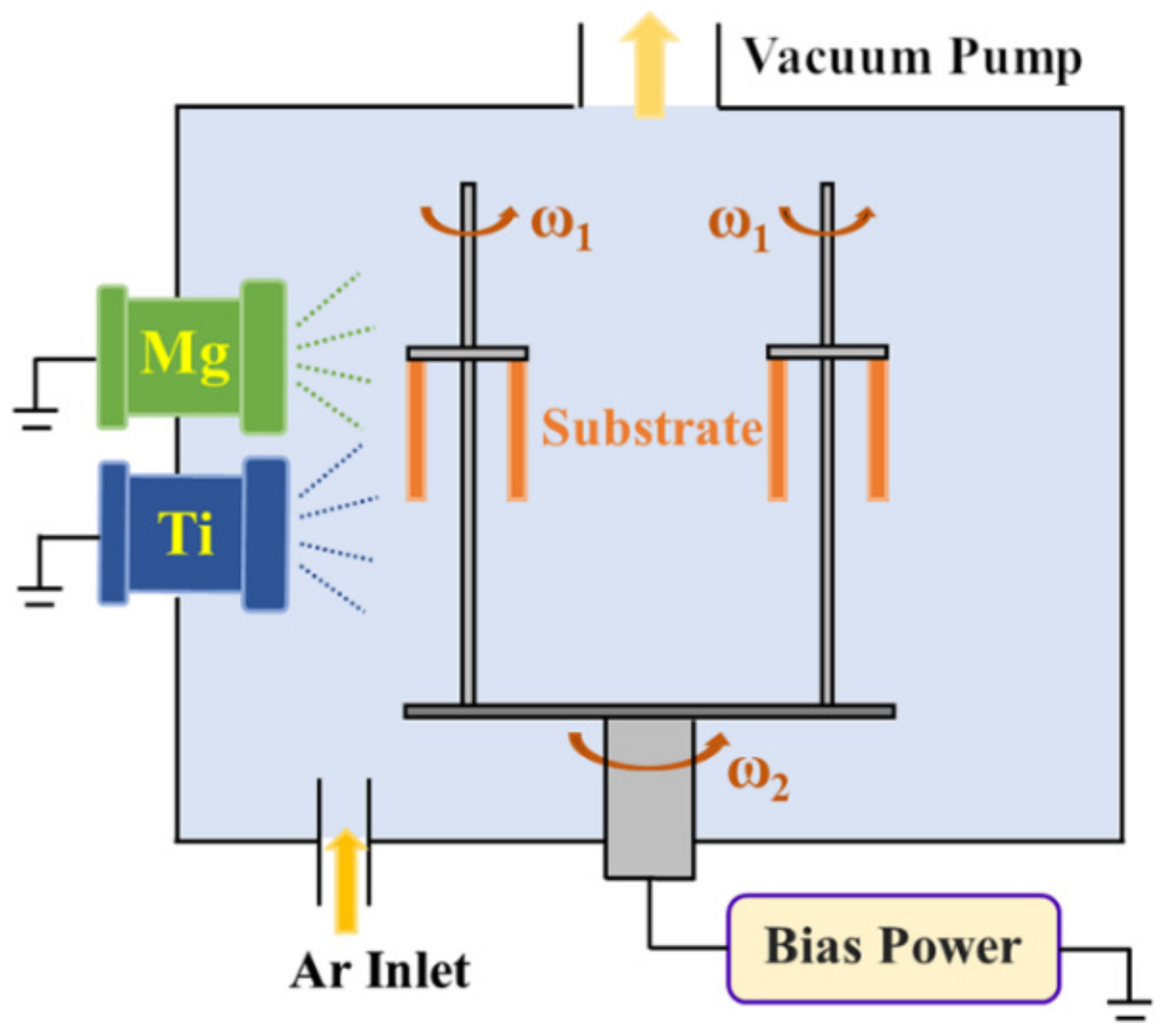
Ti-Mg immiscible alloy thin films were co-sputtered using pure Ti and Mg cathode targets via the multi-arc ion plating technique. The schematic of the multi-arc ion plating system is shown in Figure 1. The pure Ti (99.9% purity) and Mg (99.99% purity) cathode targets had diameters of 100 mm and were cross arranged on a cylindrical vacuum chamber wall. The substrate material was a Si wafer. The Si substrates were mounted on a rotational sample holder. To achieve uniform deposition, the rotation speed of the sample holder was set to 5 rpm. The minimum distance between the target and substrate was approximately 200 mm. Prior to the film deposition process, the chamber was pumped down to a base pressure of less than 4.0 × 10⁻³ Pa, and the chamber was filled with high-purity Ar gas (99.99% purity). The Si substrates were precleaned for 20 min by plasma at an argon pressure of 0.5 Pa under a negative bias voltage of −600 V. Arc cleaning was performed for the Ti and Mg cathode targets for 2 min. The target current, bias voltage, and atmosphere were critical parameters for the arc during the plating. In this study, Ti-Mg alloy thin film deposition was performed without additional substrate heating. The Ti target current was kept at 60 A. The film deposition was conducted under different Mg target currents (45, 50, and 60 A), negative bias voltages (−200, −400, and −600 V), and argon pressures (0.8, 3.2, and 5.5 Pa). The deposition time for each sample was 90 min. The detailed deposition parameters for each sample are listed in Table 1. The microstructures of the as-deposited Ti-Mg immiscible alloy thin films were investigated by X-ray diffraction (Bruker D8 Advance, Germany) with Cu Kα radiation. The cross-sections of the thin films were observed by scanning electron microscopy (SEM, Quanta 250, FEI, Hillsboro, OR, USA), and the compositions of the as-deposited thin films were determined by the energy dispersive spectrometer (EDS) in FEI Quanta 250 SEM. Further nanostructure and crystallographic analysis were conducted by transmission electron microscopy (TEM, FEI Tecnai F20, Hillsboro, OR, USA) operated at 200 kV accelerating voltage. The cross sectional TEM foil was prepared by a focused ion beam (FIB) in a FEI Scios dual beam system.
3. Results and Discussion
Figure 2 shows the surface morphologies of the as-deposited Ti-Mg alloy thin films with different negative substrate bias voltages (−200, −400, and −600 V). The Ar pressure of the vacuum chamber was held at 0.8 Pa. No cracks or pore defects were evident on the surfaces of the thin films. Microparticles of different sizes were present on the coating surface. Microparticles, which are considered to be coating defects, are commonly incorporated in thin films deposited by non-filtered cathodic arc processes. Uneven ablation and high-temperature cathode arc spots are the main reasons for target microparticle (or microdroplet) emission. Metal droplets with diameters on the order of a few microns splashed and deposited on the substrate surfaces, forming granular shapes [26,27]. These microparticles could deteriorate the performances of the thin films. The density and distribution of the microparticles were affected by the deposition parameters. As shown in Figure 2, the microparticle emission rate from the cathode increased with increasing arc current (45–60 A), which was attributed to the increase in the cathode surface temperature [28]. The density of the small size microparticles prominently decreased as the bias voltage decreased from −200 to −600 V. The microparticle filtration in the MAIP induced by applying negative bias voltage was due to the effects of ion bombardment and electrical repulsion. Collisions between the high-energy incident ions and film can result in the elimination of loosely bonded microparticles. The electrical repulsion from the substrate on the negatively charged microparticles can also act as a filter for the microparticles [29]. The decrease in the microdroplet density at a lower bias voltage (−600 V) was due to preferential sputtering of the microdroplets by the high-energy incident ions [30].
Figure 3 shows the cross-section morphologies of the as-deposited Ti-Mg thin films. Dense and compact cross-sectional structures were observed for all of the Ti-Mg thin films, and some microparticles were evident on the top surfaces of the thin films. The compositions and measured thicknesses of the Ti-Mg thin films are shown in Table 1. As shown in Figure 3, the cross-sectional structures of the Ti-Mg films were composed of columnar structures, and distinct through-film-thickness boundaries were observed in sample S8 (Figure 3h) with a Mg concentration of 77.65 at. %. Thin film samples S1–S9 had thicknesses of 1045–1619 nm, and the film deposition rates were determined to be in the range of 11.8–18.0 nm/min. A plot of the deposition rate and negative bias voltage is shown in Figure 4. The negative bias voltage had a significant influence on the film deposition rate. With the decrease in the negative bias voltage from −200 to −600 V, the deposition rate increased initially and then decreased. Under the application of negative bias voltage, the deposition rate variation may be related to the two simultaneous effects, ion acceleration and re-sputtering effects [31]. In the MAIP process, the particles deposited on the substrates were mainly composed of metal ions, neutral atoms, and target droplets. With the decrease of the negative bias voltage from −200 V to −400 V, the kinetic energy of the metal ions increased, the metal ions moved faster toward the substrate surface, the deposition rate was increased due to the ion acceleration effect. However, as the negative bias voltage further decreased to −600 V, the deposition rate decreased. A higher voltage difference between the substrate and target increased the ion bombardment energy, the re-sputtering effect due to the metal ion bombardment dominated the deposition process, resulting in a lower deposition rate. The cross-sectional structure also changed with the variation of the negative bias voltage. For samples S1, S4, and S7, the negative bias voltage was −200 V, and element contrast was evident in the thin film, indicating that Ti- and Mg-rich regions were present. When the negative bias voltage decreased to −600 V, a homogenous structure without element contrast was observed. The results demonstrated that a negative bias voltage in the multi-arc ion plating process could facilitate the mixing of the immiscible Ti and Mg elements. The Mg contents of the thin films were also affected by the negative bias voltage. For the samples with Mg target current of 50 A, as the negative bias voltage decreased from −200 to −400 V, the Mg content increased from 38.92 to 59.33 at. %. However, the Mg content decreased to 49.78 at. % with a further decrease in the negative bias voltage to −600 V. For the Ti and Mg targets, the measured ionization rate of the Mg was higher than that of Ti (approximately 80%) [32], which indicated that the plasma flux contained a high proportion of Mg metal ions, and thus, it was easier for Mg to deposit onto the substrate. With an increase in the substrate negative bias voltage, the deposition process was facilitated by the higher proportion of Mg metal ions, resulting in an increase in the Mg content in the thin film.
Figure 5 shows the XRD patterns of the Ti-Mg thin films deposited at different negative bias voltages. Diffraction peaks appeared at 2θ angles of 34.62°, 35.46°, 36.84°, and 40.40°. The peaks at 35.46° and 40.40° were identified as the hexagonal close-packed (HCP) Ti phase (PDF #44-1294, lattice parameter: a = b = 0.295 nm, c = 0.468 nm), and the diffraction peaks at 35.46° and 36.84° were identified as the HCP Mg phase (PDF#35-0821, lattice parameter: a = b = 0.321 nm, c = 0.521 nm). In addition to the HCP Ti and Mg phases, a Ti-Mg FCC supersaturated solid solution phase with a lattice parameter of a = 0.429 nm was also observed at the diffraction angle of 42.40°. The Ti-Mg FCC phase with the same lattice parameter was also reported in the ball milling process [18,33]. The intensity of the Ti-Mg FCC peaks increased as the negative bias voltage was decreased from −200 to −400 V and decreased as the negative bias voltage was decreased from −400 to −600 V. Thus, a proper negative bias voltage can facilitate the mixing of immiscible elements and the formation of a supersaturated solid solution phase. Applying a negative bias voltage increased the mobility of the vaporized Ti and Mg atoms on the surface of the growing thin film, and the higher atom mobility may have led to the phase separation of the metastable solid solution [34]. The Mg and Ti peaks in the XRD pattern may be derived from the separated Ti and Mg phases in the film or the microparticles on the surface.
To investigate the effects of the Ar gas pressure on the microstructure of the Ti-Mg immiscible alloy thin film, thin films were deposited with the different Ar gas pressures (0.8, 3.2, and 5.5 Pa) and a substrate negative bias voltage of −200 V. The surface morphologies of the as-deposited Ti-Mg thin films are shown in Figure 6. The films were relatively flat and dense, but some microparticles were still present locally. The density and sizes of the microparticles changed significantly with the variation of the Ar gas pressure, and the number and sizes of the microparticles decreased dramatically when the Ar gas pressure increased from 0.8 to 5.5 Pa, which is consistent with previous studies [35,36].
Figure 7 shows the comparison of the cross-sectional microscopic views of the Ti-Mg alloy thin films deposited at various Ar gas pressures. The thin films were well combined, and the interfaces were clear. No pronounced element contrast was observed for the S11 sample, indicating that good mixing between the Ti and Mg occurred. Upon increasing the Ar gas pressure to 5.5 Pa, columnar growth appeared throughout the entire thin-film thickness. The thin films deposited at different Ar pressures had thicknesses of 1214–1821 nm, and the film deposition rate was calculated to be in the range of 13.5–20.2 nm/min. The variation of the deposition rate with the Ar pressure is shown in Figure 8. The Ar gas pressure during the sputtering process significantly affected the film growth and the deposition rate. For the thin films deposited with Mg currents of 45 and 50 A, with the increase in the Ar gas pressure from 0.8 to 3.2 Pa, the density of the Ar ions increased. More collisionless Ti and Mg metal ions were transported to the growing thin film surface when a sufficient number of Ar ions were present, resulting in an increase in the deposition rate. Another reason for the initial increase in the deposition rate was that the density and maximum sizes of the microparticles decreased with the increase in the Ar gas pressure. For the thin films deposited with Mg current of 60 A, with the increase in the Ar gas pressure, the deposition rate first increased rapidly and then decreased. When the Ar pressure increased to 3.2 Pa, more Ti and Mg ions were directed to the growing thin film surface with enough Ar ions and high flux Mg ions, which resulted in an initial increase of deposition rate. With further increase in Ar pressure, the higher operating Ar gas pressure could not only enhance the ion bombardment effect but also increase the metal plasma and background gas interactions. These collisions reduced the ion efficiency during the substrate bombardment, and the number of metal ions reaching the substrate decreased, which resulted in a decrease in the deposition rate [37].
Figure 9 shows the XRD patterns of the Ti-Mg thin films deposited with different Ar pressures. The results showed that all of the patterns for the thin films exhibited FCC Ti-Mg structures. The intensity of the FCC phase peak was dependent on the Ar gas pressure. With the increase in the gas pressure to 3.2 Pa, the intensity of the FCC phase increased. The results indicated that the increase in the Ar gas pressure could facilitate the mixing of the immiscible Ti and Mg and the formation of a supersaturated solid solution phase. With further increase in Ar pressure, the more frequent inflight collisions between Ti and Mg atoms reduced the atom momenta, which tended to phase separation prior to reaching the substrate [34]. Consequently, the intensity of the FCC phase decreased at Ar pressure of 5.5 Pa.
TEM analysis was further employed to clarify the microstructures of the as-deposited Ti-Mg thin films. The SEM results showed that the sample S11 was well mixed without apparently element contrast (Figure 7c), indicating a low content of separated Ti and Mg phases. To further analysis the degree of mixing, the sample S11 was chosen for TEM observation. Figure 10 shows the TEM results of the Ti-Mg thin films deposited at Mg current of 45 A and Ar gas pressure of 5.5 Pa. Figure 10a shows a TEM cross-sectional micrograph of the thin film. Three distinct microstructures were present in the thin film. The columnar grains close to the interface between the Ti-Mg thin film and Si were parallel to the growth direction of the thin film. As the film deposited, nanolayer structures with thicknesses of 5 nm were present in the middle layer, and equiaxed grains with sizes of 10–30 nm appeared in the outer layer of the thin film. The discontinuous diffraction ring in the selected area electron diffraction pattern (Figure 10b) revealed that the structure of the nanocrystalline phase was composed mainly of the FCC Ti-Mg solid solution phase. Figure 10 shows a high-resolution TEM image. The d-spacing measurement and the corresponding FFT pattern also indicated that the FCC Ti-Mg phase was present, which was consistent with the XRD results. Figure 10d shows a HAADF image of the Ti-Mg thin film. The contrast in the HAADF images is associated with the atomic number of the Ti and Mg elements in the film. The white regions in the HAADF image correspond to the heavier element (Ti) in the thin film. The Ti and Mg atoms were relatively uniformly distributed in the thin film, and nano-scale elemental fluctuations were still observed. The elemental fluctuations may have arisen for two possible reasons. The collisions between the high-energy metal and Ar incident ions may have enhanced the metal atom scattering effect, resulting in the insufficient mixing of the Ti and Mg ions before the deposition. Another possible reason is that the localized temperature rise caused by the high-energy ion bombardment on the thin film surface could have triggered the phase separation of the metastable supersaturated solid solution. The phase separation included nanoscale compositional fluctuations, which have also been observed in low-temperature-annealed Cu-Fe [38] and Cu-Ag [39] immiscible alloys.
4. Conclusions
Ti-Mg immiscible alloy thin films were deposited successfully by multi-arc ion plating. The deposited Ti-Mg films were composed of FCC Ti-Mg supersaturated solid solution, HCP Ti, and HCP Mg phases. The structural and morphological properties of the Ti-Mg thin films depended strongly on the negative bias voltage and Ar gas pressure during the deposition process of the MAIP. Upon decreasing the negative bias voltage, the intensity of the FCC phase peak increased, a proper negative bias voltage could promote the mixing of immiscible elements. The sizes and density of the microparticles significantly decreased, and the deposition rate initially increased and then decreased. Upon increasing the Ar gas pressure from 0.8 to 3.2 Pa, the intensity of the FCC phase peak increased; the increase in the Ar gas pressure could facilitate the formation of FCC phase. The density of the microparticles also decreased for the thin films deposited at Mg currents of 45 and 50 A. The deposition rate increased with the increase in the Ar gas pressure for the samples deposited at Mg current of 60 A. The deposition rate first increased to 20.2 and then decreased to 17.4 nm/min. The TEM results revealed that three distinct microstructures were present in the thin films.
Author Contributions
X.W. and Y.D. conceived and designed the experiments; Y.D. and D.Q. performed the experiments; all authors analyzed the data and discussed the results; X.W. and Y.D. wrote the paper.
Funding
This research was funded by National Natural Science Foundation of China, grant number 51601129 and 51775386.
Conflicts of Interest
The authors declare no conflict of interest. The funders had no role in the design of the study; in the collection, analyses, or interpretation of data; in the writing of the manuscript; or in the decision to publish the results.
References
- Ali, M.; Hussein, M.A.; Al-Aqeeli, N. Magnesium-based composites and alloys for medical applications: A review of mechanical and corrosion properties. J. Alloys Compd. 2019, 792, 1162–1190. [Google Scholar] [CrossRef]
- Balog, M.; Ibrahim, A.M.H.; Krizik, P.; Bajana, O.; Klimova, A.; Catic, A.; Schauperl, Z. Bioactive Ti + Mg composites fabricated by powder metallurgy: The relation between the microstructure and mechanical properties. J. Mech. Behav. Biomed. Mater. 2019, 90, 45–53. [Google Scholar] [CrossRef] [PubMed]
- Bommala, V.K.; Krishna, M.G.; Rao, C.T. Magnesium matrix composites for biomedical applications: A review. J. Magnes. Alloy 2019, 7, 72–79. [Google Scholar] [CrossRef]
- Esen, Z.; Dikici, B.; Duygulu, O.; Dericioglu, A.F. Titanium-magnesium based composites: Mechanical properties and in-vitro corrosion response in Ringer’s solution. Mater. Sci. Eng. A 2013, 573, 119–126. [Google Scholar] [CrossRef]
- Liu, Y.; Li, K.; Luo, T.; Song, M.; Wu, H.; Xiao, J.; Tan, Y.N.; Cheng, M.; Chen, B.; Niu, X.R.; et al. Powder metallurgical low-modulus Ti-Mg alloys for biomedical applications. Mater. Sci. Eng. C 2015, 56, 241–250. [Google Scholar] [CrossRef]
- Jiang, S.; Huang, L.J.; An, Q.; Geng, L.; Wang, X.J.; Wang, S. Study on titanium-magnesium composites with bicontinuous structure fabricated by powder metallurgy and ultrasonic infiltration. J. Mech. Behav. Biomed. Mater. 2018, 81, 10–15. [Google Scholar] [CrossRef]
- Jiang, G.; Li, Q.; Wang, C.; Dong, J.; He, G. Fabrication of graded porous titanium–magnesium composite for load-bearing biomedical applications. Mater. Des. 2015, 67, 354–359. [Google Scholar] [CrossRef]
- Ouyang, S.; Huang, Q.; Liu, Y.; Ouyang, Z.X.; Ling, L.X. Powder metallurgical Ti-Mg metal-metal composites facilitate osteoconduction and osseointegration for orthopedic application. Bioact. Mater. 2019, 4, 37–42. [Google Scholar] [CrossRef]
- Ma, E. Alloys created between immiscible elements. Prog. Mater. Sci. 2005, 50, 413–509. [Google Scholar] [CrossRef]
- Gremaud, R.; Baldi, A.; Gonzalez-Silveira, M.; Dam, B.; Griessen, R. Chemical short-range order and lattice deformations in MgyTi1-yHx thin films probed by hydrogenography. Phys. Rev. B 2008, 77, 144204. [Google Scholar] [CrossRef]
- Murray, J.L. The Mg-Ti (Magnesium-Titanium) System. Bull. Alloy Phase Diagrams 1986, 7, 245–248. [Google Scholar] [CrossRef]
- Qi, Y.; Contreras, K.G.; Jung, H.D.; Kim, H.E.; Lapovok, R.; Estrin, Y. Ultrafine-grained porous titanium and porous titanium/magnesium composites fabricated by space holder-enabled severe plastic deformation. Mater. Sci. Eng. C 2016, 59, 754–765. [Google Scholar] [CrossRef] [PubMed]
- Alfreider, M.; Jeong, J.; Esterl, R.; Oh, S.H.; Kiener, D. Synthesis and Mechanical Characterisation of an Ultra-Fine Grained Ti-Mg Composite. Materials (Basel) 2016, 9, 688. [Google Scholar] [CrossRef] [PubMed]
- Imam, M.A.; Bruce, R.W.; Feng, J.; Fliflet, A.W. Consolidation of Blended Titanium/Magnesium Powders by Microwave Processing. Key Eng. Mater. 2013, 551, 73–85. [Google Scholar] [CrossRef]
- Suryanarayana, C.; Froes, F.H. Nanocrystalline Titanium-Magnesium Alloys through Mechanical Alloying. J. Mater. Res. 1990, 5, 1880–1886. [Google Scholar] [CrossRef]
- Liang, G.; Schulz, R. Synthesis of Mg-Ti alloy by mechanical alloying. J. Mater. Sci. 2003, 38, 1179–1184. [Google Scholar] [CrossRef]
- Wardclose, C.M.; Partridge, P.G. The Production of Titanium Magnesium Alloys by Vapor Quenching. Mater. Lett. 1991, 11, 295–300. [Google Scholar] [CrossRef]
- Wei, X.S.; Xu, W.; Xia, K. Metastable orthorhombic phases at ambient pressure in mechanically milled pure Ti and Ti-Mg. Scr. Mater. 2014, 93, 32–35. [Google Scholar] [CrossRef]
- Asano, K.; Enoki, H.; Akiba, E. Synthesis process of Mg-Ti BCC alloys by means of ball milling. J. Alloys Compd. 2009, 486, 115–123. [Google Scholar] [CrossRef]
- Cai, X.C.; Song, J.; Yang, T.T.; Peng, Q.M.; Huang, J.Y.; Shen, T.D. A bulk nanocrystalline Mg-Ti alloy with high thermal stability and strength. Mater. Lett. 2018, 210, 121–123. [Google Scholar] [CrossRef]
- Song, G.-L.; Haddad, D. The topography of magnetron sputter-deposited Mg-Ti alloy thin films. Mater. Chem. Phys. 2011, 125, 548–552. [Google Scholar] [CrossRef]
- Leegwater, H.; Schut, H.; Egger, W.; Baldi, A.; Dam, B. Divacancies and the hydrogenation of Mg-Ti films with short range chemical order. Appl. Phys. Lett. 2010, 96, 121902. [Google Scholar] [CrossRef]
- Hwang, S.; Lim, S.H.; Han, S. Highly adhesive and bioactive Ti-Mg alloy thin film on polyether ether ketone formed by PIII & D technique. Appl. Surf. Sci. 2019, 471, 878–886. [Google Scholar]
- Guan, X.; Wang, Y.; Zhang, G.; Jiang, X.; Wang, L.P.; Xue, Q.J. Microstructures and properties of Zr/CrN multilayer coatings fabricated by multi-arc ion plating. Tribol. Int. 2017, 106, 78–87. [Google Scholar] [CrossRef]
- Bai, X.; Li, J.; Zhu, L. Structure and properties of TiSiN/Cu multilayer coatings deposited on Ti6Al4V prepared by arc ion plating. Surf. Coat. Technol. 2019, 372, 16–25. [Google Scholar] [CrossRef]
- Boxman, R.L.; Goldsmith, S. Macroparticle contamination in cathodic arc coatings: generation, transport and control. Surf. Coat. Technol. 1992, 52, 39–50. [Google Scholar] [CrossRef]
- Yang, Z.; Fan, X.F.; Qiu, C.J.; Yang, X.; Liu, Y.H.; Wang, X.J. High temperature and high pressure flowing water corrosion resistance of multi-arc ion plating Cr/TiAlN and Cr/TiAlSiN coatings. Mater. Res. Express 2019, 6, 086449. [Google Scholar] [CrossRef]
- Harris, S.G.; Doyle, E.D.; Wong, Y.C.; Munroe, P.R.; Cairney, J.M.; Long, J.M. Reducing the macroparticle content of cathodic arc evaporated TiN coatings. Surf. Coat. Technol. 2004, 183, 283–294. [Google Scholar] [CrossRef]
- Cai, F.; Chen, M.H.; Li, M.X.; Zhang, S.H. Influence of negative bias voltage on microstructure and property of Al-Ti-N films deposited by multi-arc ion plating. Ceram. Int. 2017, 43, 3774–3783. [Google Scholar] [CrossRef]
- Sanchette, F.; Ducros, C.; Schmitt, T.; Steyer, P.; Billard, A. Nanostructured hard coatings deposited by cathodic arc deposition: From concepts to applications. Surf. Coat. Technol. 2011, 205, 5444–5453. [Google Scholar] [CrossRef]
- Mei, H.J.; Zhao, S.S.; Chen, W.; Wang, Q.M.; Liang, H.F. Microstructure and residual stress of TiN films deposited at low temperature by arc ion plating. T. Nonferr. Metal Soc. 2018, 28, 1368–1376. [Google Scholar] [CrossRef]
- Kimblin, C.W. Erosion and ionization in the cathode spot regions of vacuum arcs. J. Appl. Phys. 1973, 44, 3074–3081. [Google Scholar] [CrossRef]
- Asano, K.; Enoki, H.; Akiba, E. Synthesis of HCP, FCC and BCC structure alloys in the Mg-Ti binary system by means of ball milling. J. Alloys Compd. 2009, 480, 558–563. [Google Scholar] [CrossRef]
- Gohil, S.; Banerjee, R.; Bose, S.; Ayyub, P. Influence of synthesis conditions on the nanostructure of immiscible copper–silver alloy thin films. Scr. Mater. 2008, 58, 842–845. [Google Scholar] [CrossRef]
- Cai, F.; Zhang, S.H.; Li, J.L.; Chen, Z.; Li, M.X.; Wang, L. Effect of nitrogen partial pressure on Al-Ti-N films deposited by arc ion plating. Appl. Surf. Sci. 2011, 258, 1819–1825. [Google Scholar] [CrossRef]
- Li, L.; Lv, G.H.; Yang, S.Z. Effects of nitrogen partial pressure in Ta-N films grown by the cathodic vacuum arc technique. J. Phys. D: Appl. Phys. 2013, 46, 285202. [Google Scholar] [CrossRef]
- Lu, J.Q.; Yoon, J.H.; Cho, T.Y.; Joo, Y.K.; Lee, C.G. Effects of pressure on metal atom transport and plasma properties during arc ion plating of TiAlN. Met. Mater. Int. 2007, 13, 123–128. [Google Scholar] [CrossRef]
- Fu, B.; Thompson, G.B. In situ growth stresses during the phase separation of immiscible FeCu thin films. Appl. Surf. Sci. 2010, 257, 1500–1505. [Google Scholar] [CrossRef]
- Nag, S.; Mahdak, K.C.; Devaraj, A.; Gohil, S.; Ayyub, P.; Banerjee, R. Phase separation in immiscible silver-copper alloy thin films. J. Mater. Sci. 2009, 44, 3393–3401. [Google Scholar] [CrossRef]
Figure 1.
Schematic of the multi-arc ion plating coating system.

Figure 2.
Surface morphologies of the Ti-Mg thin films deposited with different substrate negative bias voltages of (a), (d) and (g) −200 V; (b), (e) and (h) −400 V; (c), (f) and (i) −600 V.
Figure 2.
Surface morphologies of the Ti-Mg thin films deposited with different substrate negative bias voltages of (a), (d) and (g) −200 V; (b), (e) and (h) −400 V; (c), (f) and (i) −600 V.
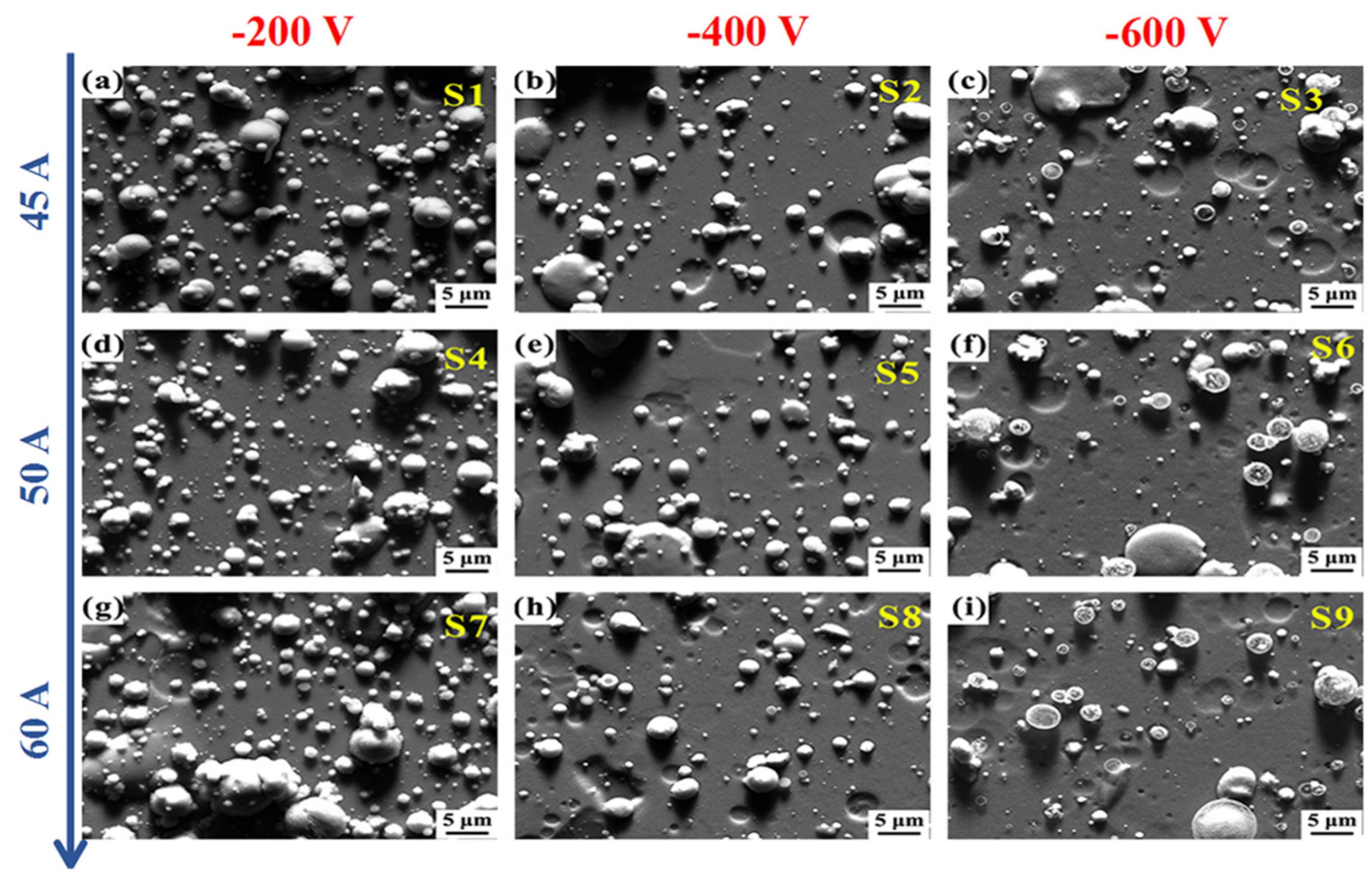
Figure 3.
Cross-sectional back-scattering SEM images of the Ti-Mg films deposited with different substrate negative bias voltages of (a), (d) and (g) −200 V; (b), (e) and (h) −400 V; (c), (f) and (i) −600 V.
Figure 3.
Cross-sectional back-scattering SEM images of the Ti-Mg films deposited with different substrate negative bias voltages of (a), (d) and (g) −200 V; (b), (e) and (h) −400 V; (c), (f) and (i) −600 V.

Figure 4.
Deposition rate of the Ti-Mg thin film as a function of substrate negative bias voltage.

Figure 5.
XRD patterns of the Ti-Mg thin films deposited with different substrate negative bias voltages.
Figure 5.
XRD patterns of the Ti-Mg thin films deposited with different substrate negative bias voltages.
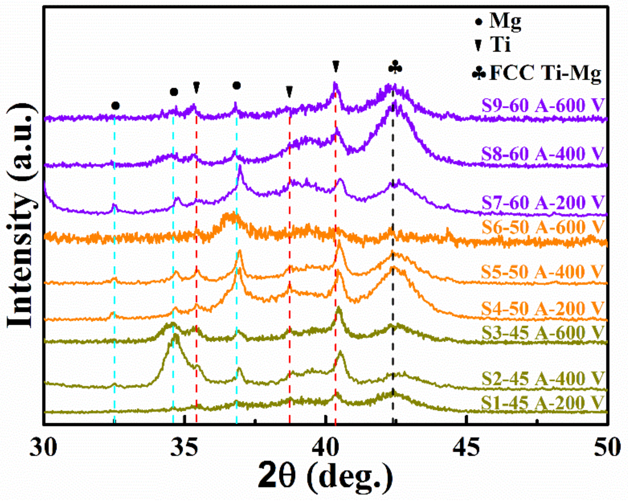
Figure 6.
Surface morphologies of Ti-Mg thin films deposited at different Ar gas pressure of (a), (d) and (g) 0.8 Pa; (b), (e) and (h) 3.2 Pa; (c), (f) and (i) 5.5 Pa.
Figure 6.
Surface morphologies of Ti-Mg thin films deposited at different Ar gas pressure of (a), (d) and (g) 0.8 Pa; (b), (e) and (h) 3.2 Pa; (c), (f) and (i) 5.5 Pa.

Figure 7.
Cross-sectional back-scattering SEM images of the Ti-Mg films deposited at different Ar pressures of (a), (d) and (g) 0.8 Pa; (b), (e) and (h) 3.2 Pa; (c), (f) and (i) 5.5 Pa.
Figure 7.
Cross-sectional back-scattering SEM images of the Ti-Mg films deposited at different Ar pressures of (a), (d) and (g) 0.8 Pa; (b), (e) and (h) 3.2 Pa; (c), (f) and (i) 5.5 Pa.

Figure 8.
Deposition rate of the Ti-Mg thin film as a function of Ar pressure.

Figure 9.
XRD patterns of Ti-Mg thin films deposited at different Ar pressures.

Figure 10.
TEM observation of the microstructure in the Ti-Mg thin films deposited at Mg current of 45 A and Ar gas pressure of 5.5 Pa (sample S11): (a) cross-sectional bright field TEM image; (b) selected area electron diffraction (SAED) pattern (taken from the position marked with a circle in the bright field image); (c) high-resolution TEM image, with the inset showing the corresponding FFT pattern; (d) HAADF image.


Table 1.
Deposition parameters of Ti-Mg thin film by multi-arc ion plating.
| Sample | Mg Target Current (A) | Bias Voltage (V) | Pressure (Pa) | Thickness (nm) | Deposition Rate (nm/min) | Ti (at. %) | Mg (at. %) |
|---|---|---|---|---|---|---|---|
| S1 | 45 | −200 | 0.8 | 1214 | 13.5 | 86.83 ± 0.73 | 13.17 ± 0.72 |
| S2 | 45 | −400 | 0.8 | 1298 | 14.4 | 65.23 ± 0.33 | 34.77 ± 0.31 |
| S3 | 45 | −600 | 0.8 | 1045 | 11.6 | 57.11 ± 0.09 | 42.89 ± 0.11 |
| S4 | 50 | −200 | 0.8 | 1317 | 14.6 | 61.08 ± 0.53 | 38.92 ± 0.53 |
| S5 | 50 | −400 | 0.8 | 1400 | 15.6 | 40.67 ± 0.51 | 59.33 ± 0.52 |
| S6 | 50 | −600 | 0.8 | 1231 | 13.7 | 50.22 ± 0.16 | 49.78 ± 0.19 |
| S7 | 60 | −200 | 0.8 | 1366 | 15.2 | 56.48 ± 0.28 | 43.52 ± 0.25 |
| S8 | 60 | −400 | 0.8 | 1400 | 15.6 | 22.35 ± 0.44 | 77.65 ± 0.45 |
| S9 | 60 | −600 | 0.8 | 1062 | 11.8 | 34.89 ± 0.62 | 65.11 ± 0.65 |
| S10 | 45 | −200 | 3.2 | 1248 | 13.9 | 43.85 ± 0.04 | 56.15 ± 0.09 |
| S11 | 45 | −200 | 5.5 | 1450 | 16.1 | 54.94 ± 0.35 | 45.06 ± 0.33 |
| S12 | 50 | −200 | 3.2 | 1366 | 15.2 | 28.93 ± 0.23 | 71.07 ± 0.24 |
| S13 | 50 | −200 | 5.5 | 1619 | 18.0 | 19.03 ± 0.14 | 80.97 ± 0.14 |
| S14 | 60 | −200 | 3.2 | 1821 | 20.2 | 11.50 ± 0.16 | 88.50 ± 0.19 |
| S15 | 60 | −200 | 5.5 | 1568 | 17.4 | 18.39 ± 0.27 | 81.61 ± 0.24 |
© 2019 by the authors. Licensee MDPI, Basel, Switzerland. This article is an open access article distributed under the terms and conditions of the Creative Commons Attribution (CC BY) license (http://creativecommons.org/licenses/by/4.0/).
Share and Cite
MDPI and ACS Style
Wei, X.; Dong, Y.; Qu, D.; Ma, T.; Shen, J. Effect of Deposition Parameters on Microstructure of the Ti-Mg Immiscible Alloy Thin Film Deposited by Multi-Arc Ion Plating. Metals 2019, 9, 1229. https://doi.org/10.3390/met9111229
AMA Style
Wei X, Dong Y, Qu D, Ma T, Shen J. Effect of Deposition Parameters on Microstructure of the Ti-Mg Immiscible Alloy Thin Film Deposited by Multi-Arc Ion Plating. Metals. 2019; 9(11):1229. https://doi.org/10.3390/met9111229
Chicago/Turabian StyleWei, Xianshun, Yue Dong, Dongdong Qu, Tiancai Ma, and Jun Shen. 2019. "Effect of Deposition Parameters on Microstructure of the Ti-Mg Immiscible Alloy Thin Film Deposited by Multi-Arc Ion Plating" Metals 9, no. 11: 1229. https://doi.org/10.3390/met9111229
Note that from the first issue of 2016, this journal uses article numbers instead of page numbers. See further details here.