Investigation of AlCrN-Coated Inserts on Cryogenic Turning of Ti-6Al-4V Alloy


1
Department of Mechanical Engineering, CEG, Anna University, Chennai 600025, Tamil Nadu, India
2
Department of Mechanical Engineering, SSN College of Engineering, Chennai 603110, Tamil Nadu, India
3
Department of Mechanical Engineering, Vel Tech Rangarajan Dr. Sagunthala R&D Institute of Science Technology, Chennai 600062, Tamil Nadu, India
*
Author to whom correspondence should be addressed.
Metals 2019, 9(12), 1338; https://doi.org/10.3390/met9121338
Submission received: 8 November 2019
/
Revised: 25 November 2019
/
Accepted: 30 November 2019
/
Published: 11 December 2019
Abstract
:Over the past decade, the focus of the metal cutting industry has been on the improvement of tool life for achieving higher productivity and better finish. Researchers are attempting to reduce tool failure in several ways such as modified coating characteristics of a cutting tool, conventional coolant, cryogenic coolant, and cryogenic treated insert. In this study, a single layer coating was made on cutting carbide inserts with newly determined thickness. Coating thickness, presence of coating materials, and coated insert hardness were observed. This investigation also dealt with the effect of machining parameters on the cutting force, surface finish, and tool wear when turning Ti-6Al-4V alloy without coating and Physical Vapor Deposition (PVD)-AlCrN coated carbide cutting inserts under cryogenic conditions. The experimental results showed that AlCrN-based coated tools with cryogenic conditions developed reduced tool wear and surface roughness on the machined surface, and cutting force reductions were observed when a comparison was made with the uncoated carbide insert. The best optimal parameters of a cutting speed (Vc) of 215 m/min, feed rate (f) of 0.102 mm/rev, and depth of cut (doc) of 0.5 mm are recommended for turning titanium alloy using the multi-response TOPSIS technique.
1. Introduction
Titanium alloys find extensive use in the field of engineering, namely, in biomedical, marine, automotive, aerospace, and petroleum refining components due to the fact of their excellent properties. Titanium alloys are noted as being tough to machine at cutting velocities higher than 30–60 m/min using high-speed steel and tungsten carbide(WC) insert tools, as they induce increased tool wear and poor workpiece surface during machining. Titanium alloys show poor machinability due to the fact of their low heat conductivity and low elastic modulus and high reactivity, strength, and hardness at the cutting zone [1]. To address problems of poor machinability, the use of coated cutting tools have been found to be essential. At present, coating represents an important aspect in the development of cutting tool technology. The coated tool can be used in high-speed machining and dry machining. The proper coating can enhance tool life enormously and increase productivity with a reduction in machining cost. Coating with enhanced mechanical properties can be performed using a simple monolayer, gradient or multilayer coatings using PVD or CVD techniques. The various coating materials used for cutting tools are known for improved performance. But the selection of the appropriate coating materials depends on the workpiece materials and cutting conditions [2]. Various coated cutting tools (e.g., TiN, TiAlN, AlTiN, CrN) are available on the market, but machining of Ti alloy still sees problems like the formation of built-up edges on the tools, a rise in wear marks on the cutting edges, and poor quality of machined surfaces. Hence, it is vital to assess the machinability characteristics of Ti alloys in the turning operation using appropriate coatings on cutting tools and advanced techniques of cryogenic lubrication.
Chauhan and Rawal [3] reported on nitride ion-based coatings, such as TiAlN, TiMoN, and TiVN, with different deposition techniques. They implied ternary nitride-based coatings showing a higher improvement in tribological and mechanical properties compared to the binary nitride coatings. Bouzakis et al. [4] discussed the evolution of cutting tool coating elements, related coating deposition techniques, manufacturing methods, recent characterization methods, film dimensional thickness, and recondition of wear on coated cutting tools. Their paper shows that as productivity increases, so does the need for improvement. Biksa et al. [5] analyzed the self-adaptive functional coating on cutting tools while machining nickel and titanium-based alloys. It showed the attainment of a better life for AlTiN/MoN-coated tools when machining Inconel 781 and AlTiN/VN-coated tools for Ti-Al6-V4 alloy. This coating was seen as having a smaller coefficient of friction at specific elevated temperatures. Nordegren et al. [6] investigated the plastic deformation modeling on layered carbide tool edges when machining AISI 4340 steel. The result indicated a determined finite element model for the edge thermal effect of the machining process.
Ghani et al. [7] indicated the failure of carbide tools during machining. This was found to be the result of a sudden fracture. This happened due to the presence of micro cracks, and failure mainly depended on the factors of cutting velocity and cutting depth. Satish et al. [8] dealt with steel of AISI 4340 grade in turning at various scales of hardness with chemical vapor and physical vapor deposition coated tools. They found best results with the use of CVD cutting tools with cutting velocity up to 180 (m/min) and a 200 (m/min) higher limit for PVD. Fernandez-abia et al. [9] examined the behavior of a PVD-coated cutting tool on the turning of austenitic steel materials. The results indicated the best performance from AlTiN compared to coatings of AlCrSiN, AlTiSiN, and TiAlCrN. Rao et al. [10] studied the significant effects of different levels of parameters in the turning operation of surface finish (Ra) and machining forces (F). Functioning of feed and depth was highly relevant to the force attained. The surface finish of a workpiece was observed. Jawahir et al. [11] presented the overall progress of cryogenic manufacturing processes and also the fundamentals of their processing, the quality of the product, and cryogenically produced components. Dhananchezian et al. [12] discussed cryogenic lubricant performance on machining AISI304 steel with a modified tool insert. It showed cryogenic coolant had a lower temperature of cutting by 44–51% compared to wet machining as well as a further improvement in the roughness (Ra) and cutting force. Pramanik [13] reviewed the Ti6Al4V alloy problem in machining and look to the various recent techniques for machining of Ti alloy; however, it was still not to the satisfaction of the industry for reducing the machine cost of Ti-alloy. Hong [14] created two mechanisms for LN2 lubrication in the cutting process. The observed results in disk test show lubrication mainly depended on the workpiece and tool materials. It also showed uncoated cutting tool inserts had less friction force compared to coated inserts under LN2 cooling. Mirghani et al. [15] supplied coolant of LN2 closer to the metal removal zone by redesigning the tool holder and increasing the machinability by lowering the temperature at the cutting zone, reducing cutting forces, the roughness of the machined surface, and increasing the life of the tool by reducing the tool wear. Nursel et al. [16] conducted the experiment without lubricant, turning AISI 316 material with and without a treated WC tool insert cryogenically. The cryo-treated tool showed better performance with the size of the grain increasing 9%, micro hardness increasing 6%, and a 34% and 54% reduction in flank and crater wear, respectively, when estimated by the untreated inserts.
Chetan et al. [17] conducted a wear analysis on deeply treated carbide inserts turning nickel-based alloy. The wear analysis with and without coated inserts with cryo-treatment were compared. The results showed the effectiveness of the deep cryogenic process, with the PVD-TiAlN carbide insert showing a relevant scaling down in the cutting force by 17% compared with the uncoated insert. Safari et al. [18] studied the cryogenic machining of Ti-6Al-4V alloy with an uncoated and coated tool insert. Machining forces (F) and roughness (Ra) were identified to be better in a coated insert compared to that of an uncoated insert. Waseem et al. [19] performed an analysis of the cutting factors and roughness on workpiece surface (Ra) in the machining of super alloy under various coated carbide inserts. The overall surface finish was found to be better, and compressive stress was noticed on the workpiece surface of the coated cemented carbide insert. Ravi and Pradeep [20] studied the D3 tool’s steel performance under cryogenic coolant during machining. It reduced the metal cutting zone temperature by 43–48% compared to non-lubricant cutting condition, but enhanced chip breakability and better surface roughness. Shokrani et al. [21] dealt with a study on the performance of Ti-6Al-4V alloy in cryogenic machining. The LN2 significantly improved in Ra, while the affected machined area was less in the cryogenic compared with flood cooling and without lubricant condition.
Based on the literature, it is noted that titanium alloy is a chemically reactive material which causes higher cutting zone temperature, cutting forces, and roughness. Researchers have used various techniques for machining titanium alloy. Coating of cutting inserts is one of the effective methods for turning titanium alloy and other chemically reactive materials. Previous researchers have used multilayered coated inserts for turning operations. However, a single-layer coating insert was found to be suitable for turning hard materials which have a smaller deterioration effect. Hence, this study aimed at investigating the effect of AlCrN monolayer-coated inserts (with a thickness of 7 µm) on cryogenic (LN2) turning of Ti-6Al-4V alloy. Also, the performance of coated inserts under cryogenic condition was optimized using the multi-response technique.
2. Materials and Methods
The workpiece used in this experiment was a Ti-6Al-4V alloy solid bar with a diameter size of 30 mm and a length of 300 mm. The mechanical properties and chemical composition of Ti-6Al-4V alloy are indicated in Table 1 and Table 2, respectively. The cutting tool inserts used in the turning were an uncoated and an AlCrN-coated tungsten carbide (ISO-CNMG120408-WIDIA) with a PCLNR 2020 M12 tool holder as shown in Figure 1. A new edge cutting insert was used for every machining experiment of the Ti-6Al-4V workpiece with a short length of 15–150 mm.
A mono layer coating of AlCrOxNx was deposited on an ISO gradeCNMG120408 THM tungsten carbide tool insert with a cathodic arc (arc-PVD-Oerlikon blazers). A factor of N2/O2 reactive gas ratio (0.9/0.1) with pressure, bias volt of 2.5 × 10⁻² mbar, and -70V were used in the process of the deposition of the coating. The insert was loaded into the rotating coating chamber after cleaning and degreasing the insert surface. The Al:Cr target used a 70:30 composition primary layer thickness, and then the top layer of AlCrOxNx was deposited on the tool insert for achieving the increased thickness level of 6–7 µm used for the investigation. The AlCrN-coated tool showed a good micro-hardness (1957 HV at 500 gm) compared to the uncoated (1575 HV at 500 gm) tool insert. Figure 2a,b show the SEM images of uncoated and coated surfaces of cutting tool inserts. The tungsten carbide particle with a shape of irregular, cubic morphology on a scale of 0.1–1.5 µm is seen with a small porosity among the particles in the uncoated insert surface. Figure 3a–c shows a cross-sectional image of an insert and a SEM photo image of the AlCrN-coated cutting tool insert with a thickness of 7 µm. The EDX indicates the elemental composition of the cutting tool surface as Al: 41.97%, Cr: 28.04%, W: 29.99% as shown in Figure 3d.
The experiments were conducted on a lathe machine with a tool dynamometer setup and cryogenic liquid nitrogen as a coolant flooded with 3 bar pressure applied to the cutting zone during machining as shown in Figure 4. The cutting force during turning operation was observed using a piezoelectric tool post dynamometer (Kistler) and the force generated was feed force (Fx), thrust force (Fy), and cutting force (Fz). Surface roughness test measurements were taken over the Ti-6Al-4V bar surface using (Gaussian filter method) a touch stylus roughness tester with a 4 mm probe travel distance. Roughness (Ra) readings were taken at two different places on the substrate. The mean value was used for investigation.
The morphological characterization of the worn tool inserts was examined by scanning the surface using electron microscopy (SEM), and the chemical elemental analysis was done using an X-ray detector (EDXS). The main control factors were doc (mm), f (mm/rev), Vc (m/min), and the three various levels as indicated in Table 3. The L27 orthogonal array of the experimental factors was used, and the value of the machining forces (F) and surface roughness (Ra) on the uncoated tool inserts (UCTs) and coated tool inserts (CTs) with cryogenic coolant conditions were seen and recorded.
3. Optimization Procedure Involved in the TOPSIS Method
The Technique for order preference by similarity to an ideal solution (TOPSIS) is a multi-criteria decision-making method for determining the best results from a finite group of alternatives. The basic concept of this method is the requirement of the preferred solution close to the ideal positive solution but far away from the negative one. This method applies to the weightage importance for each output response [22].
The output responses are Fx, Fy, Fz, and Ra.
In this study, the responses were considered as of equal weight–age. The steps given below are required for optimization in the TOPSIS method [22,23].
Step 1:
This method is the best ranking technique that picks the perfect experimental parameters that eliminate the scale of individual output measures considering only the normalized values (xij). The performance matrix of normalized values (rij) is calculated using Equation (1).
where:
- j—Denotes the output responses;
- i—Denotes the experimental runs.
Table 4 demonstrates the rij acquired using the Equation (1).
Step 2:
Determination of the weighted normalized matrix () values as the relation below follows:
where:
- wj —weight criteria;
- Number of output response—4.
Here, all four responses were treated as having equal weights, each response having a 20% weight. So, the value of wj = 20% or 0.2. The computed is listed.
Step 3:
In this stage, optimistic (S+) and pessimistic (S−) ideal solutions were determined for each response.
If the jth measure had a better performance:
But, if the jth measure had the worst performance:
Step 4:
The best determined optimistic value separated from S+ is:
Similarly, the worst determined optimistic separated from the S− is:
where:
Di+ = Distance of the best determined optimistic value from S+; Di− = distance of the worst determined optimistic from S−.
Step 5:
The nearest coefficient (Ci) values of all alternative values were determined by the below relation.
The best value of the alternative selected is the one that provided the highest nearest coefficient (Ci), because the highest Ci value is very close to the absolute ideal solution.
4. Results and Discussion
The experimental investigation was carried out under cryogenic (liquid nitrogen) conditions involving the turning of Ti-6Al-4V with coated carbide and without coated cutting inserts. The experimental responses of Ra, Fz, Fx, and Fy under uncoated inserts with cryogenic coolant were compared with AlCrN-based coated inserts with cryogenic coolant recorded. In all the turning conditions, a decrease in the main machining force (Fz) was seen with each increase in the cutting speed and an increase with an increase in the feed rates. Increasing cutting speed generated a higher cutting temperature at the metal removal zone and, consequently, softened the workpiece and thereby caused a decrease in the shear area and a decrease in the cutting force, while an increase in the feed rate followed an increase in the cutting force. A comparison of the cutting forces with the different feed rates at various cutting velocities under cryo-uncoated and cryo-coated is shown in Figure 5a–c. The cutting force (FZ) was at a feed rate of 0.205 mm/rev and the cutting velocity of 90 m/min was 246 N and 177 N for uncoated and coated inserts with cryogenic lubrication, respectively. A 28% reduction in the main cutting force due to the cryo-coated over the cryo-uncoated machining was observed. This was due to the better lubrication effect at the chip-insert rake face and the newly machined work surface-insert flank face by applying liquid nitrogen to the interacting surfaces.
The coated insert caused a decrease in the cutting force by 1−28% compared to an uncoated insert under cryogenic lubrication. This decrease in the feed force implied the provision of a lower adhesion at the friction surfaces by cryogenic cooling. In the analysis, an increase in the feed rate was seen with an increase in the cutting forces in the uncoated and AlCrN-coated tool insert during machining due to the increase in the cutting load on the tool insert. This caused metal removal on the workpiece material which was higher than the lower feed rate in the same machining. The cutting forces seen on the AlCrN-coated carbide insert were better compared to the uncoated carbide insert due to the coating of materials on the carbide insert under cryogenic cooling condition. After machining, the ideal parameters were determined based on the lower cutting forces, and the surface roughness values obtained were minimum. The parameters were Vc = 215 m/min, f = 0.102 mm/rev, doc = 0.5 mm; Vc = 135 m/min, f = 0.102 mm/rev, doc = 0.5 mm; and Vc = 215 m/min, f = 0.102 mm/rev, doc = 1.5 mm with the machining force obtained and the Ra values for the AlCrN-coated insert machining condition were 72.3 N, 74 N, 149 N and 0.78 µm, 0.89 µm, 0.91 µm. In the uncoated condition, the values were 97.5 N, 77.5 N, 160.4 N and 0.88 µm, 0.92 µm, 0.94 µm, respectively. The best parameter showed an increase in the machining speed with low depth of cut (doc) and low feed rate (f) leading to a reduction in the cutting forces (F) of the tool insert during machining and an increasing depth of cut with an increase in the cutting speed at a low feed rate, showing a minimum surface roughness on the workpiece [24,25,26].
Some imperfection in the form of irregularity is bound to be seen in any machined surface. This irregularity of the turned surface consists of peaks and valleys and is generated by the cutting tool edge. Figure 6a–c shows the changes in surface roughness with a feed rate at various cutting speeds in the turning of Ti-6Al-4V alloy under machining with uncoated and coated inserts using cryogenic lubrication. In general, the surface roughness decreases with increases in the cutting velocity as a result of the smaller build-up of materials in the insert edges and a perfect contact of insert edge with workpiece during machining. This was seen while the increasing feed rate had a negative effect on surface roughness for a related workpiece machined by uncoated inserts and a coated carbide tool insert. This was due to the effect of swelling and a side flow of the tool too fast, resulting in a relative vibration in the tool insert and a deteriorated surface finish.
A decrease in the surface roughness was seen with an increase in the velocity of cutting and an increase with an increase in the feed rate. The surface roughness figures (Ra) were 1.8 µm and 1.3 µm at a cutting velocity of 90 m/min and a feed rate of 0.159 mm/rev and depth of cut of 1.5 mm for uncoated and coated inserts, respectively. This is explained by the lubrication of liquid nitrogen applied on the tool insert–chip interface, insert surface of the flank of the workpiece machined, and in the cutting tool insert which resulted in a reduced cutting temperature, less adhesion between the workpiece surface generated and the tool auxiliary surface of the flank, and less tool wear on the insert edge. The LN2 cooling with a coated cutting tool causes a decrease in the roughness of a workpiece surface (Ra) by 1–27% over an uncoated insert [27,28].
Optimization of Cryogenic Turning Performance Using TOPSIS
In this section, multi-response criteria model was used for finding the optimum cutting parameters, namely, tool type with coolant condition, feed rate, cutting speed, and depth of cut on machining forces and surface finish. Table 4 shows the computed Di+, Di−, and Ci values. The coated tool with cryogenic coolant (CC) showed the highest Ci value at a cutting speed (Vc) of 215 m/min, feed (f) of 0.102 mm/rev, and depth (doc) of 0.5 mm. The output responses under uncoated inserts with cryogenic coolant were compared.
Finding correct input parameters is a significant element in machining for reducing operating cost and improving product quality. Optimization of process parameters is essential, mainly for the turning operation. The TOPSIS method was used for obtaining the optimum output responses and input variable in the investigation. Experiment run 48 had the maximum Ci value in comparison to other Ci values. A higher Ci value was obtained at the cutting speed of 215 m/min, feed rate 0.102 mm/rev, and doc 0.5 mm for coated inserts with cryogenic coolant condition (CC). It provided the perfect multi-response characters among the 54 runs to the ideal solution (+1); the 48th experiment run yielded correct turning parameters for the multi-criteria output responses of the turning of the Ti-6Al-4Valloy. The related outputs of experiment run 48 with the lowest values were Fx 61.6 N, Fy 92.9N, Fz 72.4 N, and Ra 0.78 µm. The formulated Ci values in the individual experiments are shown in Figure 7. The output responses of the turning Ti6Al4V alloy in a cryogenic environment with uncoated and coated insert conditions at Vc 215 m/min, f 0.102 mm/rev, and doc 0.5 mm are shown in Table 5.
Worn carbide tools were investigated during the machining of Ti-6Al-4Valloy with AlCrN-coated and uncoated inserts, including the various types of wear pattern, namely, crater and flank, observed using SEM images. Figure 8 shows the effects of the machining speed on the worn tool inserts after machining with varying cutting speeds of 90, 135, and 215 m/min, depth of cut of 0.5 mm, and feed of 0.102 mm/rev. The impact of feed, depth of cut, and cutting speed on the worn tool inserts revealed the crater and flank wear on the insert, also showing the formation of built-up edges on the various tool inserts at a lower cutting speed. At the same time, a higher cutting speed showed smaller built-up edges on the inserts. The formation of built-up edges on the uncoated carbide tool insert was identified [29,30,31]. The reason behind this was the active adhesion of workpiece elements on the carbide cutting insert edges. The wear observed by metallographic sectioning was attained with abrasion and adhesion as the wear mechanism [32,33,34]. It also showed the AlCrN-coated tool insert having a smaller width of tool wear compared to the uncoated insert by the impact of depth of cut, feed, and cutting speed. Hence, the flank wear, built-up edge, and adhesion were smaller on the AlCrN-coated tool insert under the machining condition of cryogenic cooling [33,34].
Figure 9 shows the SEM image with EDX composition analysis with a 15 kV accelerating voltage and magnification of 1000× on the worn rake face of the carbide tool insert edge after machining with the parameters of cutting speed 215 m/min, feed 0.102 mm/rev, and depth (doc) 0.5 mm. The SEM image confirmed the development of a built-up layer on the tool rake edge faces of the both the UCT and CT inserts. This was the result of a higher contact pressure and heat involved in the turning process. Elements such as Ti, V, Cr, C, Al, and W were also seen. The presence of Ti, Al, and V elements on the cutting insert edge confirmed the occurrence of adhesion between the Ti-6Al-4V alloy and cutting inserts. This result happened due to the softening of the interface zone in the work material. In addition, the presence of W and Cr indicated that the abrasive wear occurred between the chip and cutting insert. The coated insert was seen as having a higher weight percentage of Ti and Al than that of the uncoated insert. This happened due to the higher material removal along with cutting zone temperature. The conclusion from the results was the predominant role played by adhesion in an uncoated insert against the major role played by both adhesion and abrasion in AlCrN-coated inserts.
5. Conclusions
In this paper, an experimental investigation was conducted and an optimization of parameters used on turning Ti-6Al-4Valloy using uncoated and coated inserts under cryogenic performance was discussed. The conclusions from this study are as follows.
- Cryogenic cooling with a coated cutting tool lowered the main cutting force (Fz) by 1–28% compared to the uncoated insert. The cutting force in the AlCrN-coated cutting tool insert showed a decrease due to the hardness in the coated insert surface.
- The uncoated insert produced irregular surface profile peaks which caused a poor surface finish, and the AlCrN-coated insert showed improvement in the roughness value. Cryogenic cooling with a coated cutting insert caused a reduction in the roughness of the workpiece surface (Ra) by 1–27% over an uncoated insert.
- The best optimal parameters were suggested by TOPSIS at a cutting speed of (Vc) = 215 m/min, feed rate (f) = 0.102 mm/rev, and (doc) = 0.5 mm with the responses Fx 61.6 N, Fy 92.9 N, Fz 72.4 N, Ra 0.78 µm.
- The SEM analysis showed the building of material adhesion and abrasion on the rake and flank face of the insert higher on the uncoated tool insert compared to the AlCrN-coated insert. Analysis of the EDX image and composition on the worn tool insert edge showed the built-up edges on the WC tool inserts and an element composition of Ti, V, Si, C, Al, and W of workpiece material on the uncoated insert edge and AlCrN-coated edge.
- This investigation proves the coated cutting insert with lubrication of cryogenic LN2 coolant created a better surface finish on machined Ti-6Al-4V alloy and less tool wear. This was due to the smaller edge chipping which led to smaller mechanical impact results, higher strength of the tool tip, and heat reduction at the machining zone which improved tool life.
Author Contributions
L.S. wrote the manuscript; P.K.M. assisted with correction and revision of the manuscript; D.M. assisted with data interpretation; Y.N. assisted with SEM image analysis.
Funding
This research received no external funding.
Conflicts of Interest
The authors declare no conflicts of interest.
References
- Ezugwu, E.O.; Wang, Z.M. Titanium alloys and their machinability—A review. J. Mater. Process. Technol. 1997, 68, 262–274. [Google Scholar] [CrossRef]
- Yang, X.; Liu, C.R. Machining titanium and its alloys. Int. J. Mach. Sci. Technol. 2007. [Google Scholar] [CrossRef]
- Chauhan, K.V.; Rawal, S.K. A review paper on tribological and mechanical properties of ternary nitride-based coatings. Procedia Technol. 2014, 14, 430–437. [Google Scholar] [CrossRef] [Green Version]
- Bouzakis, K.D.; Michailidis, N.; Skordaris, G.; Bouzakis, E.; Biermann, D.; M’Saoubi, R. Cutting with coated tools: Coating technologies, Characterization methods and performance optimization. CIRP Ann. Manuf. Technol. 2012, 61, 703–723. [Google Scholar] [CrossRef]
- Biksa, A.; Yamamoto, K.; Dosbaeva, G.; Veldhuis, S.C.; Fox-Rabinovich, G.S.; Elfizy, A.; Wagg, T.; Shuster, L.S. Wear behavior of adaptive nano multilayered AlTiN/MexN PVD coatings during machining of aerospace alloys. Tribol. Int. 2010, 43, 1491–1499. [Google Scholar] [CrossRef]
- Anders, N.; Bktash, Z.S.; Richid, M.S. Experimental study and modelling of plastic deformation of cemented carbide tools in turning. Procedia CIRP 2014, 14, 599–604. [Google Scholar]
- Ghani, J.A.; Haron, C.H.C.; Hamdan, S.-H.; Said, A.Y.M.; M Tomadi, S.-H. Failure mode analysis of carbide cutting tools used for machining titanium alloy. Ceram. Int. 2013, 39, 4449–4456. [Google Scholar] [CrossRef]
- Satish, C.; Choudhury, S.K. Investigation on machinability aspects of hardend AISI 4340 steel at different level of hardness busing coated carbide tools. Int. J. Refract. Met. Hard Mater. 2013, 38, 124–133. [Google Scholar]
- Fernandez-abia, A.I.; Barrerio, J.; Fernandez-Larrinoa, J.; Lopez, L.N.; Ferenandez-Valdivieiso, A.; Pereira, O.-M. Behaviour of PVD coatings in the turning of austenitic stainless steels. Procedia Eng. 2014, 63, 133–141. [Google Scholar] [CrossRef] [Green Version]
- Rao, C.J.; Nageswara, R.-D.; Srihari, P. Influence of cutting parameters on cutting force and surface finish in turning operation. Procedia Eng. 2013, 64, 1405–1415. [Google Scholar]
- Jawahir, I.S.; Attia, H.; Biermann, D.; Duflou, J.; Klocke, F.; Meyer, D.; Newman, S.T.; Pusavec, F.; Putz, M.; Rech, J.; et al. Cryogenic manufacturing processes. CIRP Ann. Manuf. Technol. 2016, 65, 713–736. [Google Scholar] [CrossRef]
- Dhananchezian, M.; Pradeepkumar, M.; Sornakumar, T. Cryogenic turning of AISI 304 stainless steel with modified tungsten carbide tool inserts. Mater. Manuf. Process. 2011, 26, 781–785. [Google Scholar] [CrossRef]
- Pramanik, A. Problems and solutions in machining of titanium alloys. Int. J. Adv. Manuf. Technol. 2014. [Google Scholar] [CrossRef]
- Hong, S.-Y. Lubrication mechanism of liquid nitrogen in ecological cryogenic machining. Mach. Sci. Technol. 2007. [Google Scholar] [CrossRef]
- Mirghani, I.A.; Ahmed, F.I.; Abakr, Y.A.; Nurual, A.K.M. Effectiveness of cryogenic machining with modified tool holder. J. Mater. Process. Technol. 2007. [Google Scholar] [CrossRef]
- Nursel, A.O.; Adem, C.; Mahmut, G.; Onur, O. Effect of cutting conditions on wear performance of cryogenically treated tungsten carbide inserts in dry turning of stainless steel. Tribol. Int. 2016, 94, 223–233. [Google Scholar]
- Ghosh, S.; Rao, P.V. Performance evaluation of deep cryogenic processed carbide inserts during dry turning of Nimonic 90 aerospace grade alloy. Tribol. Int. 2017, 115, 392–408. [Google Scholar]
- Safari, H.; Sharif, S.; Izman, S.; Jafari, H.; Kurniawan, D. Cutting Force and Surface Roughness Characterization in Cryogenic High-Speed End Milling of Ti–6Al-4V ELI. Mater. Manuf. Process. 2014, 29, 350–356. [Google Scholar] [CrossRef]
- Waseem, A.; Jianfei, S.; Wuyi, C. Effect of Machining Parameters on Surface Integrity in High Speed Milling of Super Alloy GH4169/Inconel 718. Mater. Manuf. Process. 2016, 31, 620–627. [Google Scholar]
- Ravi, S.; Pradeepkumar, M. Experimental investigations on cryogenic cooling by liquid nitrogen in the end milling of hardened steel. Cryogenics 2011, 51, 509–515. [Google Scholar] [CrossRef]
- Shokrani, A.; Dhokia, V.; Newman, S.T. Investigation of the effects of cryogenic machining on surface integrity in CNC end milling of Ti–6Al–4V titanium alloy. J. Manuf. Process. 2016, 21, 172–179. [Google Scholar] [CrossRef] [Green Version]
- Yuvaraj, N.; Pradeep Kumar, M. Multiresponse Optimization of Abrasive Water Jet cutting process parameters using TOPSIS Approach. Mater. Manuf. Process. 2015, 30, 882–889. [Google Scholar] [CrossRef]
- Jebaraj, M.; Pradeep Kumar, M.; Yuvaraj, N.; Mujibar Rahman, G. Experimental study of the influence of the process parameters in the milling of Al6082-T6 alloy. Mater. Manuf. Process. 2019, 34, 1411–1427. [Google Scholar] [CrossRef]
- Mohanty, A.; Gangopadhyay, S.; Thakur, A. On Applicability of Multilayer Coated Tool in Dry Machining of Aerospace Grade Stainless Steel. Mater. Manuf. Process. 2016, 31, 869–879. [Google Scholar] [CrossRef]
- Emel, K. Nose radius and cutting speed effects during milling of AISI 304 material. Mater. Manuf. Process. 2017, 32, 185–192. [Google Scholar]
- Sivaiah, P.; Chakradhar, D. Influence of cryogenic coolant on turning performance characteristics: A comparison with wet machining. Mater. Manuf. Process. 2017, 32, 1475–1485. [Google Scholar] [CrossRef]
- Zhao, W.; Gong, L.; Ren, F.; Li, L.; Xu, Q.; Khan, M.-A. Experimental study on chip deformation of Ti-6Al-4V titanium alloy in cryogenic cutting. Int. J. Adv. Manuf. Technol. 2018, 96, 4021. [Google Scholar] [CrossRef] [Green Version]
- Salman, P.; Amir, R.; Ibrahim, D.; Nicolescu, M.-C. An experimental investigation on effect of minimum quantity cooling lubrication (MQCL) in machining titanium alloy (Ti6Al4V). Int. J. Adv. Manuf. Technol. 2016, 87, 1371–1386. [Google Scholar] [CrossRef]
- Priarone, P.C.; Klocke, F.; Faga, M.-G.; Lung, D.; Settineri, L. Tool life and surface integrity when turning titanium aluminides with PCD tools under conventional wet cutting and cryogenic cooling. Int. J. Adv. Manuf. Technol. 2016, 85, 807. [Google Scholar] [CrossRef]
- Bai, D.; Sun, J.; Chen, W.; Wang, T. Wear mechanisms of WC/Co tools when machining high-strength titanium alloy TB6 (Ti-10V-2Fe-3Al). Int. J. Adv. Manuf. Technol. 2017, 90, 2863. [Google Scholar] [CrossRef]
- Lin, H.; Wang, C.; Yuan, Y.; Chen, Z.; Wang, Q.; Xiong, W. Tool wear in Ti-6Al-4V alloy turning under oils on water cooling comparing with cryogenic air mixed with minimal quantity lubrication. Int. J. Adv. Manuf. Technol. 2015, 81, 87. [Google Scholar] [CrossRef]
- Rashid, R.R.A.; Palanisamy, S.; Sun, S.; Dargusch, M.-S. Tool wear mechanisms involved in crater formation on uncoated carbide tool when machining Ti6Al4V alloy. Int. J. Adv. Manuf. Technol. 2016, 83, 1457. [Google Scholar] [CrossRef]
- Shi, L. Investigation of tool wear and surface roughness when turning titanium alloy (Ti6Al4V) under different cooling and lubrication conditions. Ferroelectrics 2017. [Google Scholar] [CrossRef]
- Sartori, S.; Taccin, M.; Pavese, G.; Ghiotti, A.; Bruschi, S. Wear mechanisms of uncoated and coated carbide tools when machining Ti6Al4V using LN2 and cooled N2. Int. J. Adv. Manuf. Technol. 2018, 95, 1255. [Google Scholar] [CrossRef]
Figure 1.
Cutting tool inserts and holder.

Figure 2.
SEM image of the cutting insert surface: (a) uncoated insert; (b) AlCrN-coated insert.
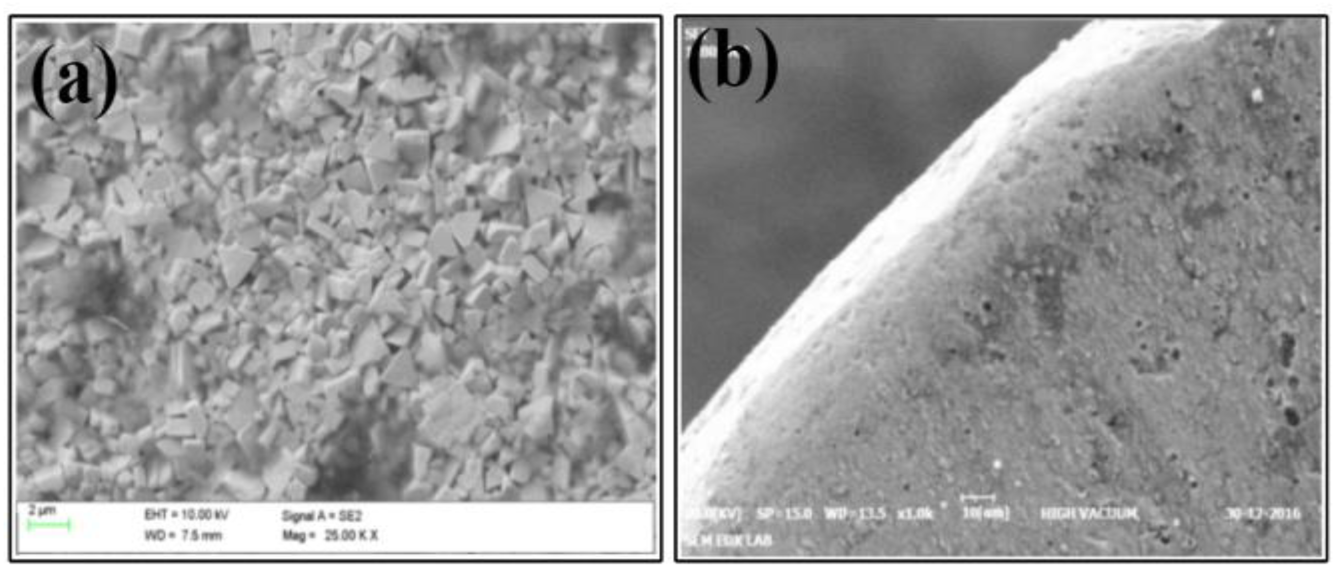
Figure 3.
(a) Cross-section of the insert, (b) Prepared insert specimen for the SEM analysis, (c) SEM image coating thickness of the insert, (d) Elemental composition of the insert surface by EDX.
Figure 3.
(a) Cross-section of the insert, (b) Prepared insert specimen for the SEM analysis, (c) SEM image coating thickness of the insert, (d) Elemental composition of the insert surface by EDX.
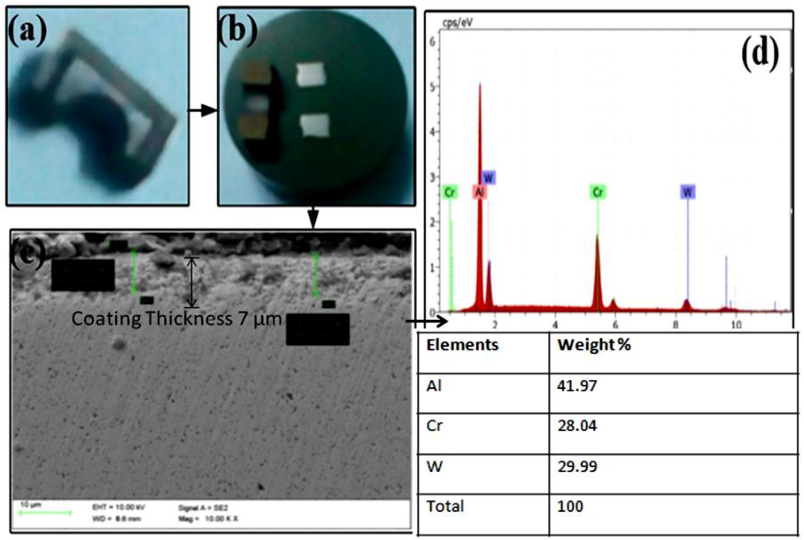
Figure 4.
The experimental setup for cryogenic turning.

Figure 5.
Cutting forces under cryo-uncoated and cryo-coated: (a) doc = 0.5 mm, (b) doc = 1 mm, (c) doc = 1.5 mm.
Figure 5.
Cutting forces under cryo-uncoated and cryo-coated: (a) doc = 0.5 mm, (b) doc = 1 mm, (c) doc = 1.5 mm.
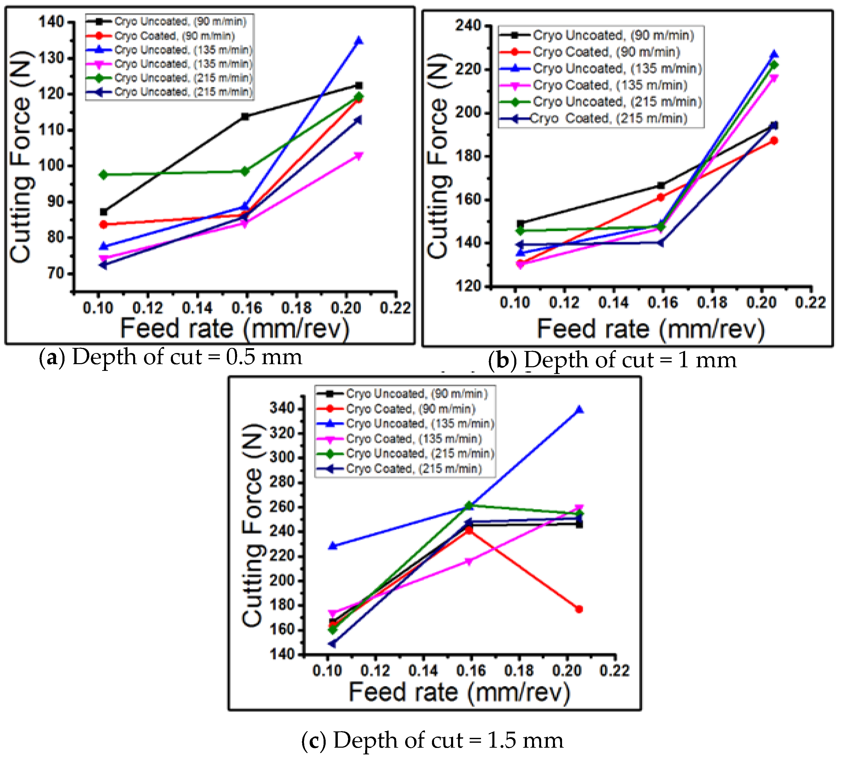
Figure 6.
Surface roughness under cryo-uncoated and cryo-coated: (a) doc = 0.5 mm, (b) doc = 1 mm, (c) doc = 1.5 mm.
Figure 6.
Surface roughness under cryo-uncoated and cryo-coated: (a) doc = 0.5 mm, (b) doc = 1 mm, (c) doc = 1.5 mm.
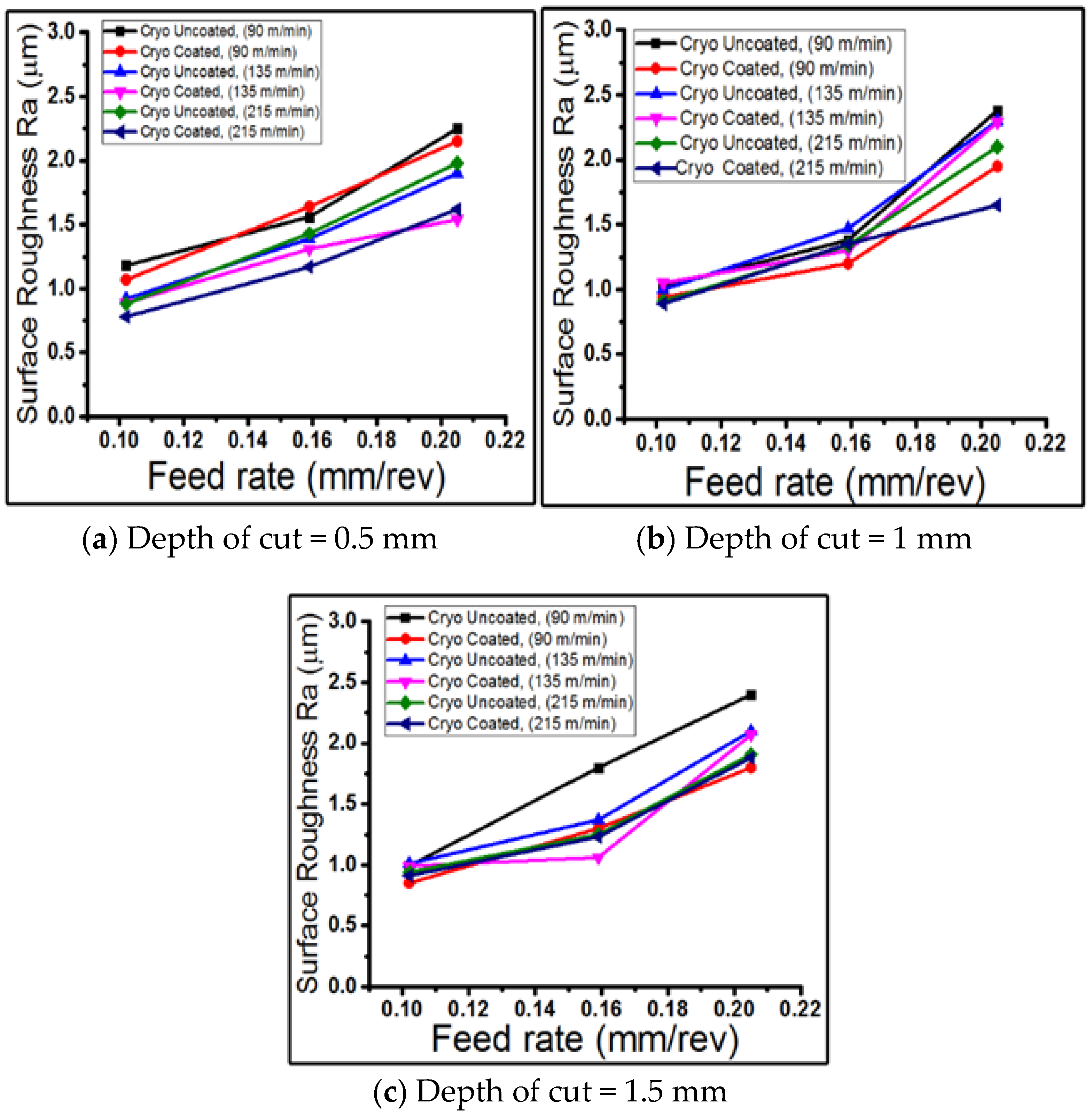
Figure 7.
The different closeness coefficient Ci values for the respective experiment.

Figure 8.
SEM image of tool insert with feed (f) = 0.102 mm/rev, depth of cut (doc) = 0.5 mm with varying speeds of 90, 135, and 215 m/min.
Figure 8.
SEM image of tool insert with feed (f) = 0.102 mm/rev, depth of cut (doc) = 0.5 mm with varying speeds of 90, 135, and 215 m/min.
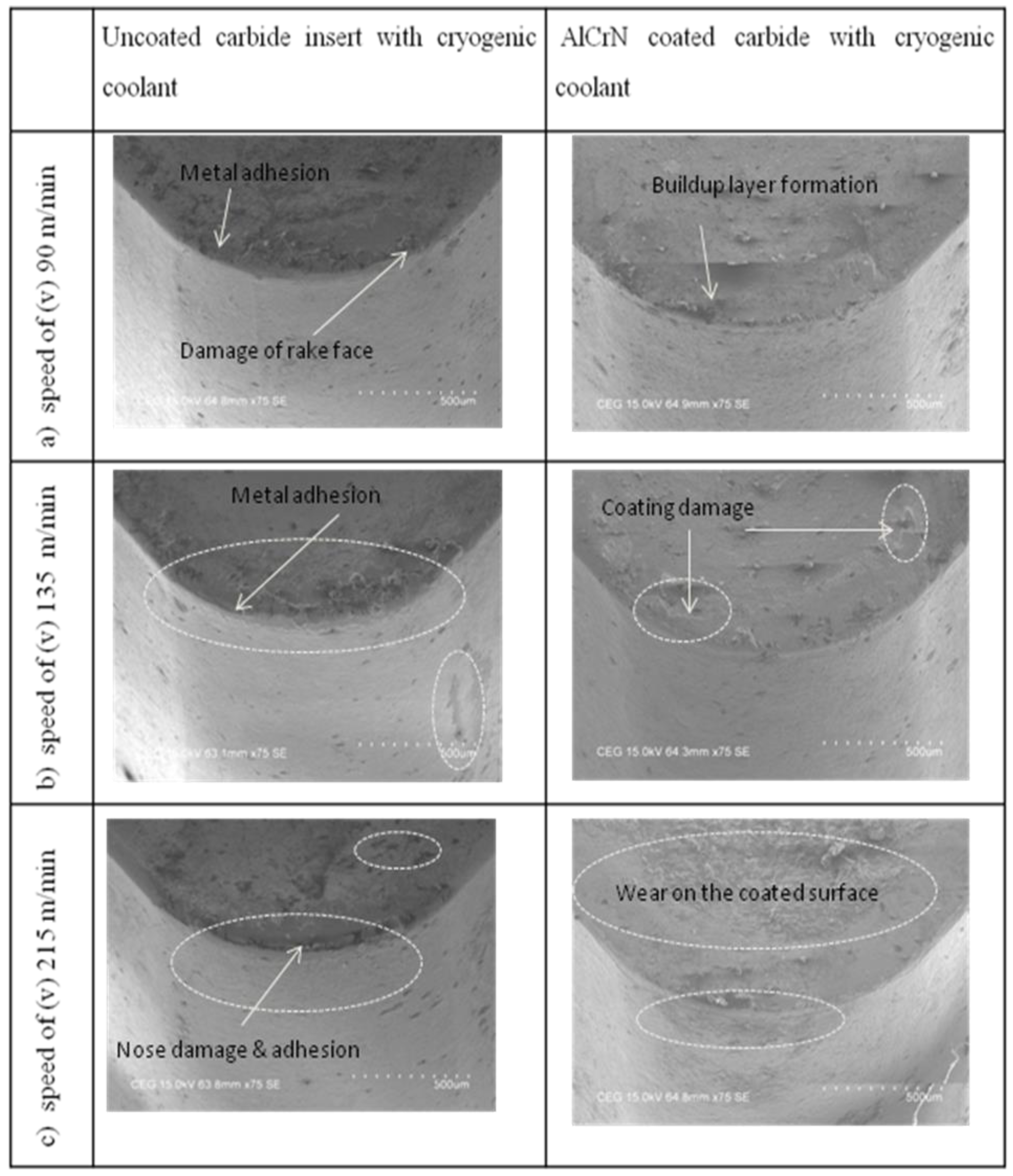
Figure 9.
Chemical composition and EDXS with the parameters of VC = 215 m/min, f = 0.102 mm/rev and doc = 0.5 mm with cryogenic LN2 coolant: (a) uncoated tool and (b) AlCrN-coated tool.
Figure 9.
Chemical composition and EDXS with the parameters of VC = 215 m/min, f = 0.102 mm/rev and doc = 0.5 mm with cryogenic LN2 coolant: (a) uncoated tool and (b) AlCrN-coated tool.


Table 1.
Composition of titanium alloy.
| Elements | Weight (%) |
|---|---|
| Al | 5.5–6.75 |
| V | 3.5–4.5 |
| Fe | <0.25 |
| C | <0.08 |
| Ti | Remaining |
Table 2.
Mechanical properties of titanium alloy.
| Properties | Value |
|---|---|
| Tensile strength | 345 MPa |
| Yield strength | 276 MPa |
| Percent elongation | 22% |
| Hardness | 80 HRB |
Table 3.
Control factors and levels used in the experiments.
| Symbols | Control Factors | Levels | ||
|---|---|---|---|---|
| 1 | 2 | 3 | ||
| T | Tool condition with coolant | UCC | CC | |
| X | Speed (VC)(m/min) | 90 | 135 | 215 |
| Y | Feed (f)(mm/rev) | 0.102 | 0.159 | 0.205 |
| Z | Depth of cut (DOC) (mm) | 0.5 | 1 | 1.5 |
Table 4.
Closeness coefficient (Ci) values and ranking of alternatives by TOPSIS.
| Experiment Order | T | X | Y | Z | Closeness Alternatives Value | Experiment Order | T | X | Y | Z | Closeness Alternatives Value | ||
|---|---|---|---|---|---|---|---|---|---|---|---|---|---|
| Ci | Rank | Ci | Rank | ||||||||||
| 1 | Uncoated insert with cryogenic coolant (UCC) | 215 | 0.205 | 1.5 | 0.2952 | 50 | 28 | Coated insert with cryogenic coolant (CC) | 215 | 0.205 | 1.5 | 0.3161 | 49 |
| 2 | 215 | 0.159 | 1.5 | 0.4384 | 37 | 29 | 215 | 0.159 | 1.5 | 0.4148 | 40 | ||
| 3 | 215 | 0.102 | 1.5 | 0.6862 | 11 | 30 | 215 | 0.102 | 1.5 | 0.5606 | 30 | ||
| 4 | 135 | 0.205 | 1.5 | 0.1781 | 53 | 31 | 135 | 0.205 | 1.5 | 0.2714 | 52 | ||
| 5 | 135 | 0.159 | 1.5 | 0.3355 | 48 | 32 | 135 | 0.159 | 1.5 | 0.3854 | 44 | ||
| 6 | 135 | 0.102 | 1.5 | 0.4063 | 42 | 33 | 135 | 0.102 | 1.5 | 0.2819 | 51 | ||
| 7 | 90 | 0.205 | 1.5 | 0.1156 | 54 | 34 | 90 | 0.205 | 1.5 | 0.4027 | 43 | ||
| 8 | 90 | 0.159 | 1.5 | 0.5750 | 26 | 35 | 90 | 0.159 | 1.5 | 0.3651 | 46 | ||
| 9 | 90 | 0.102 | 1.5 | 0.5631 | 28 | 36 | 90 | 0.102 | 1.5 | 0.5166 | 32 | ||
| 10 | 90 | 0.102 | 1 | 0.6226 | 20 | 37 | 90 | 0.102 | 1 | 0.5992 | 23 | ||
| 11 | 90 | 0.159 | 1 | 0.5482 | 31 | 38 | 90 | 0.159 | 1 | 0.5018 | 34 | ||
| 12 | 90 | 0.205 | 1 | 0.3662 | 45 | 39 | 90 | 0.205 | 1 | 0.4915 | 35 | ||
| 13 | 135 | 0.102 | 1 | 0.5970 | 25 | 40 | 135 | 0.102 | 1 | 0.6177 | 21 | ||
| 14 | 135 | 0.159 | 1 | 0.4371 | 38 | 41 | 135 | 0.159 | 1 | 0.5154 | 33 | ||
| 15 | 135 | 0.205 | 1 | 0.3440 | 47 | 42 | 135 | 0.205 | 1 | 0.4321 | 39 | ||
| 16 | 215 | 0.102 | 1 | 0.5976 | 24 | 43 | 215 | 0.102 | 1 | 0.6774 | 13 | ||
| 17 | 215 | 0.159 | 1 | 0.6139 | 22 | 44 | 215 | 0.159 | 1 | 0.5738 | 27 | ||
| 18 | 215 | 0.205 | 1 | 0.4805 | 36 | 45 | 215 | 0.205 | 1 | 0.4115 | 41 | ||
| 19 | 215 | 0.205 | 0.5 | 0.6592 | 16 | 46 | 215 | 0.205 | 0.5 | 0.7182 | 8 | ||
| 20 | 215 | 0.159 | 0.5 | 0.7415 | 7 | 47 | 215 | 0.159 | 0.5 | 0.7931 | 3 | ||
| 21 | 215 | 0.102 | 0.5 | 0.7157 | 9 | 48 * | 215 | 0.102 | 0.5 | 0.8378 | 1 | ||
| 22 | 135 | 0.205 | 0.5 | 0.5610 | 29 | 49 | 135 | 0.205 | 0.5 | 0.6848 | 12 | ||
| 23 | 135 | 0.159 | 0.5 | 0.6372 | 18 | 50 | 135 | 0.159 | 0.5 | 0.6602 | 15 | ||
| 24 | 135 | 0.102 | 0.5 | 0.7715 | 5 | 51 | 135 | 0.102 | 0.5 | 0.8212 | 2 | ||
| 25 | 90 | 0.205 | 0.5 | 0.6586 | 17 | 52 | 90 | 0.205 | 0.5 | 0.6249 | 19 | ||
| 26 | 90 | 0.159 | 0.5 | 0.7106 | 10 | 53 | 90 | 0.159 | 0.5 | 0.6673 | 14 | ||
| 27 | 90 | 0.102 | 0.5 | 0.7698 | 6 | 54 | 90 | 0.102 | 0.5 | 0.7822 | 4 | ||
Table 5.
Optimal output responses in coated inserts with cryogenic and uncoated with cryogenic.
| Tool Conditions with Cryogenic Coolant | Feed Force (Fx) N | Thrust Force (Fy) N | Cutting Force (Fz) N | Surface Roughness (Ra) µm |
|---|---|---|---|---|
| CC | 61.26 | 92.9 | 72.4 | 0.78 |
| UCC | 95.34 | 138 | 98.6 | 0.88 |
© 2019 by the authors. Licensee MDPI, Basel, Switzerland. This article is an open access article distributed under the terms and conditions of the Creative Commons Attribution (CC BY) license (http://creativecommons.org/licenses/by/4.0/).
Share and Cite
MDPI and ACS Style
Selvam, L.; Murugesan, P.K.; Mani, D.; Natarajan, Y. Investigation of AlCrN-Coated Inserts on Cryogenic Turning of Ti-6Al-4V Alloy. Metals 2019, 9, 1338. https://doi.org/10.3390/met9121338
AMA Style
Selvam L, Murugesan PK, Mani D, Natarajan Y. Investigation of AlCrN-Coated Inserts on Cryogenic Turning of Ti-6Al-4V Alloy. Metals. 2019; 9(12):1338. https://doi.org/10.3390/met9121338
Chicago/Turabian StyleSelvam, Lakshmanan, Pradeep Kumar Murugesan, Dhananchezian Mani, and Yuvaraj Natarajan. 2019. "Investigation of AlCrN-Coated Inserts on Cryogenic Turning of Ti-6Al-4V Alloy" Metals 9, no. 12: 1338. https://doi.org/10.3390/met9121338
Note that from the first issue of 2016, this journal uses article numbers instead of page numbers. See further details here.