A Fatigue Life Prediction Model Based on Modified Resolved Shear Stress for Nickel-Based Single Crystal Superalloys


1
School of Energy and Power Engineering, Beihang University, Beijing 100191, China
2
Collaborative Innovation Center for Advanced Aero-Engine, Beijing 100191, China
*
Author to whom correspondence should be addressed.
Metals 2019, 9(2), 180; https://doi.org/10.3390/met9020180
Submission received: 4 January 2019
/
Revised: 27 January 2019
/
Accepted: 29 January 2019
/
Published: 2 February 2019
(This article belongs to the Special Issue Fatigue and Fracture of Traditional and Advanced Structural Alloys)
Abstract
:In this paper, the viewpoint that maximum resolved shear stress corresponding to the two slip systems in a nickel-based single crystal high-temperature fatigue experiment works together was put forward. A nickel-based single crystal fatigue life prediction model based on modified resolved shear stress amplitude was proposed. For the four groups of fatigue data, eight classical fatigue life prediction models were compared with the model proposed in this paper. Strain parameter is poor in fatigue life prediction as a damage parameter. The life prediction results of the fatigue life prediction model with stress amplitude as the damage parameter, the fatigue life prediction model with maximum resolved shear stress in 30 slip directions as the damage parameter, and the McDiarmid (McD) model, are better. The model proposed in this paper has higher life prediction accuracy.
1. Introduction
Nickel-based single crystal superalloy materials are mainly used in engine turbine blades, and their working environment is very harsh, which is why they are one of the components with the most structural failures. Many authors have conducted a number of experimental and theoretical studies on turbine blades. Some authors have focused on experiments and microscopic observations to investigate the fatigue behavior of nickel-based single crystals with different orientations, and some nickel-based single crystal fatigue life prediction models have been proposed. However, these have mostly been improved models of isotropic material life prediction and are often phenomenological life prediction models. Based on experiments, other scholars have conducted in-depth studies on the deformation behavior of nickel-based single crystals and have established some nickel-based single crystal constitutive models to simulate deformation, finally realizing prediction of fatigue life.
A large amount of literature has described the effect of resolved shear stress on fatigue. Ref. [1] mentions that plastic deformation mainly concentrates on the octahedral slip plane at low and medium temperatures, but both octahedral slip systems and cubic slip systems are activated at high temperatures (>600 °C). According to [2], for directional solidification superalloys, it is found that the crack mainly lies in the primary octahedral slip systems when the temperature is between 500 °C and 600 °C. The fracture surface presents crystallographic features. When the temperature is higher than 700 °C, the Ι type crack is dominant. With temperatures between 600 °C and 700 °C, the fracture surface has the two aforementioned fracture characteristics. Ref. [3] mentions that at lower temperatures, octahedral slip systems will cause crystallographic fracture. At higher temperatures the ’wavy’ slip will cause the fracture to be perpendicular to the loading direction and crack initiation sites will be mostly located on micro-holes near the subsurface. Most crack initiations comprise multiple sources. Ref. [4] considers that at room temperature and at 300 °C the cracks exhibit a non-crystallographic expansion mode and the crack initiation sites are mostly located on the persistent slip band. At 600 °C, cracks tend to expand along the crystallographic slip plane, and cracks propagating along slip lines on surfaces of specimens have been observed. Sliding surfaces and surface slip lines correspond to the primary octahedral slip system, so resolved shear stress plays an important role in crack initiation and propagation.
A large amount of literature describes the activation of nickel-based single crystal slip systems. For the SC16 nickel-based single crystal superalloy, [5] considers that the primary octahedral slip system is activated in the [001] loading direction at a temperature of 950 °C. Plastic deformation was found on the corresponding crystallographic plane. Ref. [6] mentions that inhomogeneous planar dislocations distributed in strip form have been observed from room temperature to 800 °C, and that the dislocation structure became gradually homogeneous as the temperature was further increased. For the nickel-based single crystal superalloys, it is believed that with increases in experimental temperature, the cubic slip system is gradually activated when loaded in the [001] direction [7]. As the temperature increases further, the quantity of the cubic slip also increases further, and the quantity of the octahedral slip gradually decreases. In Ref. [8], for nickel-based single crystal superalloys, it has been noted that inelastic deformation corresponding to the [001] loading direction is dominated by octahedron slip systems and that inelastic deformation corresponding to the [111] loading direction is dominated by cubic slip systems. Secondary octahedral systems have been observed only after a long period of creep deformation. Creep fatigue interaction experiments have been conducted for the SRR99 nickel-based single crystal superalloy at 950 °C, and the phenomenological model of the nickel-based single crystal superalloy has been proposed based on the isotropous constitutive model. It can be seen that with an increase in temperature the primary octahedral slip system and the cubic slip system are both activated, and under the influence of creep, the secondary octahedral slip system is also activated. Therefore, at higher temperatures, there is a certain influence of the three slip systems on the fatigue life of nickel-based single crystals.
Some literature has determined the activated slip system by observing slip lines on the surface of specimens. In Ref. [9], monotonic tensile tests were carried out for PWA1480 notch specimens at room temperature. The primary octahedral slip system was considered active. The maximum resolved shear stress on the specimen surface near the notch was calculated. Slip lines based on maximum resolved shear stress were consistent with experimental observations of the surface. In Ref. [10], a cylindrical indentation experiment using PWA1480 at room temperature was carried out. It was also noted that the primary octahedral slip system was activated. The numerical calculation results of the surface slip lines of the specimens were consistent with experimental observations. For the PWA1480 notch specimens [11], a monotonic tensile experiment was carried out at room temperature, obtaining the same conclusions as those drawn in [9,10]. In Ref. [12], a monotonic tensile experiment of copper single crystal notch specimens at room temperature was conducted. It was noted that the primary octahedral slip system was activated, and it was postulated that single slips, double slips, and multiple slips might be generated with different loading directions, theoretically. However, there are manufacturing deviations and loading direction deviations due to the installation process of the specimens causing there to be only a single slip with a [001] loading direction. Thus, in the beginning, the largest resolved shear stress in primary octahedral slip systems plays a significant role. It can be seen that only the primary octahedral slip system is activated at room temperature and the corresponding maximum resolved shear stress plays a major role.
The theoretical calculation methods regarding resolved shear stress and shear strain of nickel-based single crystals are listed in the theoretical formulae section. Eight kinds of nickel-based single crystal fatigue life prediction models are listed in the next section, and the viewpoint that maximum resolved shear stress corresponding to the two slip systems in a nickel-based single crystal high temperature fatigue experiment work together is proposed. A nickel-based single crystal fatigue life prediction model based on modified resolved shear stress amplitude is proposed. In the third section, for the four groups of fatigue data, eight classical fatigue life prediction models are compared with the model proposed in this paper. The advantages and disadvantages of the current several nickel-based single crystal fatigue life prediction models and the model proposed in this paper are separately described and discussed.
2. Methods
2.1. Elastic Stress and Strain Calculation of Nickel-Based Single Crystal
The coordinate system consisting of the three principal axes is the material coordinate system . Correspondingly the calculation coordinate system is defined by ox’y’z’. The property of each material axis is described by three elastic parameters, respectively; these are the elastic modulus E, Poisson’s ratio υ, and shear modulus G, where . According to the theory of elastic mechanics, in the material coordinate system, the stress-strain relation is or , in which C is the flexibility matrix and D is the elasticity matrix. ε and σ represent the strain and stress vectors, respectively:
Nickel-based single crystal material is one type of the commonly used materials utilized for turbine blades and is an orthotropic cubic symmetric material. In the three major axis directions of the material coordinate system, the elastic parameters of the material are equal, respectively. The elastic parameters in the three directions are: , , and . li, mi, and ni are the cosines of the angles between the material coordinate system and the calculation coordinate system, respectively. The specific correspondence relationship is shown in Table 1.
According to geometry relationships, the transformation matrix A and B of the material coordinate system and the calculation coordinate system can be expressed as
Furthermore, . By using the transformation matrix, stress and strain in the calculation coordinate system can be obtained [13]:
From and , can be obtained; similarly, can be obtained. In actual engineering analysis, the material coordinate system and the calculation coordinate system are often not uniform and between them there is a certain angle. The coordinate transformation matrix A can be used to convert the elasticity matrix D in the material coordinate system to the elasticity matrix in the calculation coordinate system. contains 21 different elements:
When the elastic moduli , , and are known, the three independent material parameters E, υ, and G can be calculated using the coordinate transformation.
2.2. Nickel-Based Single Crystal Resolved Shear Stress and Resolved Shear Strain
In the material coordinate system, the relationship between resolved shear stress and the stress tensor is , in which , is the sliding direction of the α slip system, and is the normal direction of the plane of the α slip system. The solution to the resolved shear stresses of the 12 primary octahedral slip systems is showed in Equation (6). The solution to the resolved shear stresses of the 12 secondary octahedral slip systems is shown in Equation (7). The solution to the resolved shear stresses of the six cubic slip systems is shown in Equation (8). The corresponding resolved shear strains of the different slip systems were calculated by a similar formula to that used for the resolved shear stresses.
The formula can be used to convert the stress tensor in the oxyz coordinate system to the ox’y’z’ coordinate system. The ox’ axis in the new coordinate system ox’y’z’ corresponds to the normal direction of the slip plane and hence the normal stress of the slip plane can be calculated as , in which , , and . The direction cosines between the old and new coordinate systems are shown in Table 2.
2.3. Nickel-Based Single Crystal Fatigue Life Prediction Model
This article lists eight classic nickel-based single crystal fatigue life prediction models (see Table 3); parameters in these models may be calculated using Equations (6)–(8). The damage parameter of model (1) is the maximum resolved shear stress amplitude, which may be obtained by taking the maximum value of the 30 resolved shear stress amplitudes. The damage parameter of model (2) is the maximum value of the 12 resolved shear stress amplitudes corresponding to the primary octahedral slip system. The model (3) damage parameter is the maximum resolved shear strain amplitude, which may be obtained by taking the maximum value of the 30 resolved shear strain amplitudes. The damage parameter of model (4) is the maximum value of the 12 resolved shear strain amplitudes corresponding to the primary octahedral slip system. The model (5) damage parameter is the maximum shear stress range. Model (6) obtains the resolved shear strain range, the maximum resolved shear stress, the normal strain amplitude, and the maximum normal stress respectively corresponding to the 30 slip directions. The left side of model (6) is first obtained, the maximum value of which is taken as the damage parameter. For model (7), the resolved shear stress amplitudes and corresponding maximum normal stresses are obtained respectively considering the 30 slip directions. The left side of model (7) is first obtained, the maximum value of which is taken as the damage parameter. For model (8), the maximum resolved shear stress amplitude and the maximum normal stress in the 30 slip directions are calculated, the combination of which is used as the damage parameter. The difference between model (7) and model (8) is that for the former the resolved shear stress amplitude and the maximum normal stress correspond, while for the latter resolved shear stress amplitude does not necessarily correspond to the maximum normal stress.
2.4. Modified Life Prediction Model
A single crystal fatigue life prediction model based on a modified resolved shear stress amplitude is proposed. M1 and M2 are the maximum and median values of the Schmid factor corresponding to the maximum resolved shear stress in the primary octahedral slip system, the secondary octahedral slip system, and the cubic slip system, respectively, which are obtained from the following two equations:
The nickel-based single crystal fatigue life prediction model can be obtained as follows:
According to fatigue experiment data about different loading directions of nickel-based single crystal materials, compared to other classic nickel-based single crystal fatigue life models, the fatigue life prediction accuracy of the proposed model is higher. Compare the Schmid factor with the modified factor (M1 + M2)/2, as shown in Figure 1. Figure 1a corresponds to the maximum Schmid factor only considering the primary octahedral slip system. Figure 1b corresponds to the maximum Schmid factor only considering the secondary octahedral slip system. Figure 1c corresponds to the maximum Schmid factor considering the cubic slip system. Figure 1d corresponds to the maximum Schmid factor considering all three slip systems. In Figure 1e, compared to Figure 1d, only the primary octahedral slip system and the cubic slip system are activated. Figure 1f corresponds to the model proposed in this paper, namely, the modified factor (M1 + M2)/2. The plane formed by the x-axis and y-axis corresponds to the standard projection plane. Because of the spatial symmetry of the nickel-based single crystal material, all the loading directions can be represented by one point in the black line zone.
When considering only the primary octahedral slip system, the Schmid factor corresponding to the [111] direction is less than that for the [001] and [011] directions. The experiment data shows that the stress level in the [111] direction is greater than that in the [001] and [011] directions in the uniaxial loading with the same fatigue life. However, when the fatigue life prediction method only considering the resolved shear stress of the primary octahedral slip system is adopted, the calculated resolved shear stress in the [111] direction tends to be smaller. According to [14,16], three slip systems for low cyclic fatigue at 648 °C can be activated for PWA1480 material and it has been concluded that the maximum resolved shear stress amplitude model has good prediction effect. For the primary octahedral slip system and the cubic slip system, the maximum Schmid factor for the [111] loading direction is greater than the maximum Schmid factor for the [001] and [011] loading directions. For the three slip systems, the maximum Schmid factor for the [111] loading direction is equal to the maximum Schmid factor for the [001] and [011] loading directions. However, for the monotonic tensile tests, the stress loading in the [111] direction is often greater than that in the [001] and [011] directions with the same fatigue life. Therefore, the nickel-based single crystal fatigue life prediction model which considers the three slip systems or the primary octahedral slip system and the cubic slip system is often inconsistent with its experimental results; this will be discussed further.
3. Results
For the above nine nickel-based single crystal fatigue life prediction models, the high cyclic fatigue data for DD6 material at 700 °C and 800 °C, the low cycle fatigue data for PWA1480 material at 648 °C, and the high cycle fatigue data for PWA1484 material at 593 °C were used to predict uniaxial fatigue life. The plasticity effect was not considered. The basic material properties of the three materials are shown in Table 4.
On the one hand, the fatigue life prediction model was selected by comparing the adjusted coefficient of determination (Adj. R_Square), where the coefficient of determination is and the adjusted coefficient of determination is . ni is the experimental sample freedom and k is the number of explanatory variables in the model (excluding the constants in the model). On the other hand, the fatigue life prediction model was selected by comparing the size of the fatigue life dispersion zone. In view of the fact that the calculation results are based on pure elastic static analysis, the prediction results of the single crystal life prediction models, including the elastic strain, tend to be poor, as shown by Model (3) and Model (4) in Table 3. Fatigue life prediction results of Model (3) and Model (4) are not listed.
3.1. High Cycle Fatigue Life Prediction for DD6 Material
(1) DD6 material at 700 °C
High cyclic fatigue data for DD6 material at 700 °C was selected for analysis [17]. The experiments were carried out according to the loading directions of [001], [011], and [111], with a stress ratio of −1. The results are shown in Figure 2 and Figure 3.
For the high cyclic fatigue experiment using DD6 material at 700 °C with a stress ratio of −1, the fatigue life model with stress amplitude as the damage parameter, the fatigue life model with the maximum resolved shear stress amplitude considering 30 slip systems as the damage parameter, the Fin model, the McD model, and the model proposed in this paper produced relatively higher Adj. R_Square values and better life prediction results. The results of the fatigue life prediction model which only uses the resolved shear strain as the damage parameter were poor. The fatigue life prediction results obtained using the model which only considers the maximum resolved shear stress of the primary octahedral slip system as the damage parameter, and the Chu-Conle-Bonnen (CCB) model, were worse. The fatigue life prediction results of most data points using modified maximum resolved shear stress amplitude as the damage parameter proposed in this paper were within three times of the dispersion band. The fatigue life prediction model proposed in this paper can be used to predict fatigue life with high accuracy for high cyclic fatigue experimental data for DD6 material at 700 °C with a stress ratio of −1.
(2) DD6 material at 800 °C
High cyclic fatigue data for DD6 material at 800 °C was selected for analysis [17]. Experiments were carried out according to the loading directions of [001], [011], and [111], and the stress ratio was −1. The fatigue life prediction results are shown in Figure 4 and Figure 5.
For the high cyclic fatigue experiment for DD6 material at 800 °C with a stress ratio of −1, the fatigue life model with stress amplitude as the damage parameter, the fatigue life model with maximum resolved shear stress amplitude considering the 30 slip systems as the damage parameter, the Fin model, the McD model, and the model proposed model in this paper gave relatively higher Adj. R_Square values and better life prediction results. The comparison results are the same as for DD6 material at 700 °C. The fatigue life prediction results of all the data points using modified maximum resolved shear stress amplitude as the damage parameter proposed in this paper were within three times of the dispersion band. The fatigue life prediction model proposed in this paper can be used to predict fatigue life with high accuracy for high cyclic fatigue experimental data for DD6 material at 800 °C with a stress ratio of −1.
3.2. Low Cycle Fatigue Life Prediction for PWA1480 Material
Analysis was performed for PWA1480 material with 648 °C low cycle fatigue data [14]. In order to facilitate comparison with the literature, experiments were conducted using the [001], [011], [111], and [213] loading directions, respectively, with different strain ratios controlled. The stress tensor and resolved shear stress were obtained by using the elasticity matrix [14]. The fatigue life prediction results are shown in Figure 6 and Figure 7.
For the low cyclic fatigue experiment using PWA1480 material at 648 °C with different strain ratios, the fatigue life model with stress amplitude as the damage parameter, the fatigue life model with maximum resolved shear stress amplitude considering the 30 slip systems as the damage parameter, the CCB model, the McD model, and the model proposed in this paper produced relatively higher Adj. R_Square values and better life prediction results. The fatigue life prediction results of most data points using modified maximum resolved shear stress amplitude as the damage parameter proposed in this paper were within three times of the dispersion band. The fatigue life prediction results of all the data points were within ten times of the dispersion band. The fatigue life prediction model proposed in this paper can be used to predict fatigue life with high accuracy for low cyclic fatigue experimental data for PWA1480 material at 648 °C with different strain ratios.
3.3. Fatigue Life Prediction of PWA1484 Material
Analysis was performed on the PWA1484 material at 593 °C with a stress ratio of 0.1 fatigue data [15]. Experiments were carried out according to the loading directions of [001], [011], and [111], respectively. The experiment loading frequency was 30 Hz. The fatigue life prediction results are shown in Figure 8 and Figure 9.
For the fatigue experiment data for PWA1484 material at 593 °C with a stress ratio of 0.1, due to the large data dispersion, the fatigue life prediction results using the eight models mentioned above and the model proposed in this paper were worse. The life prediction model could not ensure that the prediction effect was located within ten times of dispersion. However, compared with the life prediction results of the other eight kinds of damage parameters, the Adj. R_Square value of the model proposed in this paper was higher and was only inferior to that value for the model with maximum resolved shear stress of the primary octahedral slip system. This was mainly due to the lower experimental temperature which resulted in the primary octahedral slip system playing a dominant role and the role of the secondary octahedral slip system and the cubic slip system not being obvious.
4. Discussion
Based on the prediction results of the four groups of nickel-based single crystal fatigue life data, all the fatigue life prediction models are summarized in Table 5.
Ref. [18] focuses on a fatigue experiment using thin plates with cooling holes at 900 °C for DD6 material, establishing the nickel-based single crystal plastic constitutive model and combining it with the critical distance method to predict its fatigue life. The fatigue life prediction method used in [18] which is based on a nickel-based single crystal fatigue constitutive model is complicated. It takes a long time to calculate the stress and strain of single crystal hollow blades with complex cooling structures. In addition, the program in [18] is unstable and is not easy to apply in engineering. Ref. [19] uses a modified Mücke’s anisotropic model to predict fatigue life. Using a solution of a nonlinear equation to determine the model parameters in [19] is a tedious process. The multiaxial fatigue life prediction of a CMSX-2 nickel-based single crystal material at 900 °C with stress controlled for is performed in [20]. The result of the fatigue life prediction model with stress as the damage parameter is generally better than the fatigue life prediction model with strain as the damage parameter, which is consistent with the conclusion in this paper. Ref. [14,15,20] have adopted the same idea as this paper, selecting appropriate damage parameters and establishing nickel-based single crystal fatigue life prediction methods.
However, the model proposed in this paper does not consider the effect of plastic, which has no effect on predictions of high cycle fatigue life. The fatigue life prediction results are better than other models. For predictions of low cycle fatigue life, the material has often yielded, and the experiments are often strain controlled. The stress tensor and resolved shear stress are obtained by using the elasticity matrix; thus, the stress levels of some data points in Figure 6a will appear larger. In the absence of a stress gradient, the model proposed in this paper still has a good prediction accuracy of low cycle fatigue life. Although the corresponding damage parameters are fictitious, they still have a good one-to-one correspondence with life. Due to the deficiency of data, the effects of average stress and stress gradient are not considered in this paper. Ref. [21,22,23] have established life prediction models for the effects of stress gradient for uniaxial and multiaxial fatigue, respectively. As a next step, the right side of the model proposed in this paper can be modified to introduce the influence of average stress [24], and the stress gradient factor can be introduced into the model based on the nickel-based single crystal notch experiment [21].
In Ref. [25], monotonic tensile tests of a MD2 nickel-based single crystal superalloy at room temperature were conducted and it was observed that the cracks often initiated near the inclusions or holes. The initiation position was often located on the surface or near the surface of the specimen. In Ref. [5], monotonic tensile tests for SC16 at 950 °C were conducted, and it was concluded that micro-cracks on the surface and the casting holes of the specimens were often potential crack initiation sites. In Ref. [26], notch ultra-high cycle fatigue experiments for CMSX-4 and CM186LC at 850 °C were conducted, and crack initiation was often related to the interaction of the persistent slip band (PSB) with casting holes or carbides. At the same time, the life of crack initiation accounts for most of the total life. The actual life of the specimen often depends on the state of the material at the crack initiation position. Casting holes and inclusions often produce large stress concentrations, especially near the surface. Therefore, it is appropriate to predict the high cycle fatigue life of the material with crack initiation near the casting hole or the inclusion with stress as the damage parameter. To facilitate applications within engineering, it is still applicable to extend this method to low cycle fatigue life prediction.
5. Conclusions
- For the high cyclic fatigue experiments for DD6 material at 700 °C and 800 °C with a stress ratio of −1 and the low cyclic fatigue experiments for PWA1480 material at different strain ratios at 648 °C, several classical nickel-based single crystal fatigue life prediction models were compared. The fatigue life prediction model with stress amplitude as the damage parameter, the fatigue life prediction model considering maximum resolved shear stress of the 30 slip directions as the damage parameter, the McD model, and the modified maximum resolved shear stress amplitude fatigue life prediction proposed in this paper were observed to have higher accuracy.
- For fatigue data obtained for PWA1484 material at 593 °C with a stress ratio of −1, the fatigue life prediction model proposed in this paper and the model considering maximum resolved shear stress of the primary octahedral slip system as the damage parameter had better prediction results. At lower temperatures, the model considering maximum resolved shear stress of the primary octahedral slip system as the damage parameter has greater engineering application prospects.
- Fatigue life prediction models with strain as the damage parameter have poor prediction accuracy.
- By comparing the aforementioned nickel-based single crystal fatigue life prediction models, for nickel-based single crystals at higher temperature, the proposed method and the fatigue life model with stress amplitude directly as the damage parameter have higher prediction accuracy and hence greater engineering application value.
Author Contributions
Methodology, J.W., D.W. and Y.W.; Formal analysis, X.J.; Data curation, X.J.; Writing—original draft preparation, J.W.; Writing—review and editing, D.W. and Y.W.
Funding
This research was funded by the National Natural Science Foundation of China (grant No. 51475024).
Conflicts of Interest
The authors declare no conflict of interest. The funders had no role in the design of the study; in the collection, analyses, or interpretation of data; in the writing of the manuscript, or in the decision to publish the results.
Nomenclature
| a | Fatigue strength coefficient |
| b | Fatigue strength exponent |
| A, B | Transformation matrix |
| C | Flexibility matrix |
| D | Elasticity matrix |
| E | Young’s modulus |
| G | Shear modulus |
| li, mi, ni | Cosines of the angle between the material coordinate system and the calculation coordinate system |
| lj | Firection cosines between the old and new coordinate systems |
| m(a) | Sliding direction of the αth slip system |
| n(a) | Normal direction of the plane of the αth slip system |
| M1 | Maximum value of the Schmid factor |
| M2 | Median value of the Schmid factor |
| Nf | Number of cycles to failure |
| ε | Strain tensor |
| Δεs,oct_prim | Maximum resolved shear strain range (the primary octahedral slip system) |
| Δεn | Normal strain corresponding to the resolved shear strain |
| Δεs | Maximum resolved shear strain range |
| υ | Poisson’s ratio |
| σ | Stress tensor |
| σmax | Maximum normal stress |
| τmax | Maximum shear stress |
| Δτmax | Maximum shear stress range |
| Δτ | Maximum resolved shear stress range |
| τ(a) | Resolved shear stress of the αth slip system |
| Δτs,oct_prim | Maximum resolved shear stress range (the primary octahedral slip system) |
| Δτoct_sec | Maximum resolved shear stress range (the secondary octahedral slip system) |
| Δτcub | Maximum resolved shear stress range (the cubic octahedral slip system) |
References
- Palmert, F.; Moverare, J.; Gustafsson, D.; Busse, C. Fatigue crack growth behaviour of an alternative single crystal nickel base superalloy. Int. J. Fatigue 2018, 109, 166–181. [Google Scholar] [CrossRef]
- He, Z.W.; Zhang, Y.Y.; Qiu, W.H.; Shi, H.-J.; Gu, J. Temperature effect on the low cycle fatigue behavior of a directionally solidified nickel-base superalloy. Mater. Sci. Eng. A 2016, 676, 246–252. [Google Scholar] [CrossRef]
- Ma, X.F.; Shi, H.J.; Gu, J.L.; Wang, Z.; Harders, H.; Malow, T. Temperature effect on low-cycle fatigue behavior of nickel-based single crystalline superalloy. Acta Mech. Solida Sin. 2008, 21, 289–297. [Google Scholar] [CrossRef]
- Zhang, Y.Y.; Shi, H.J.; Gu, J.L.; Li, C.; Kadau, K.; Luesebrink, O. Crystallographic analysis for fatigue small crack growth behaviors of a nickel-based single crystal by in situ SEM observation. Theor. Appl. Fract. Mech. 2014, 69, 80–89. [Google Scholar] [CrossRef]
- Wahi, R.P.; Auerswald, J.; Mukherji, D.; Dudka, A.; Fecht, H.-J.; Chen, W. Damage mechanisms of single and polycrystalline nickel base superalloys SC16 and IN738LC under high temperature LCF loading. Int. J. Fatigue 1997, 19, 89–94. [Google Scholar] [CrossRef]
- Li, P.; Li, Q.Q.; Jin, T.; Zhou, Y.Z.; Li, J.G.; Sun, X.F.; Zhang, Z.F. Comparison of low-cycle fatigue behaviors between two nickel-based single-crystal superalloys. Int. J. Fatigue 2014, 63, 137–144. [Google Scholar] [CrossRef]
- Wang, J.J.; Guo, W.G.; Su, Y.; Zhou, P.; Yuan, K. Anomalous Behaviors of a single-crystal nickel-base superalloy over a wide range of temperatures and strain rates. Mech. Mater. 2016, 94, 79–90. [Google Scholar] [CrossRef]
- Li, S.X.; Smith, D.J. Development of an anisotropic constitutive model for single-crystal superalloy for combined fatigue and creep loading. Int. J. Mech. Sci. 1998, 40, 937–948. [Google Scholar] [CrossRef]
- Sabnis, P.A.; Mazière, M.; Forest, S.; Arakere, N.K.; Ebrahimi, F. Effect of secondary orientation on notch-tip plasticity in superalloy single crystals. Int. J. Plasticity 2012, 28, 102–123. [Google Scholar] [CrossRef]
- Sabnis, P.A.; Fores, S.; Arakere, N.K.; Yastrebova, V.A. Crystal plasticity analysis of cylindrical indentation on a Ni-base single crystal superalloy. Int. J. Plasticity 2013, 51, 200–217. [Google Scholar] [CrossRef]
- Arakere, N.K.; Siddiqui, S.; Magnan, S.; Ferroro, L. Investigation of three-dimensional stress fields and slip systems for FCC single crystal superalloy notched specimens. J. Eng. Gas Turbines Power 2005, 127, 629–637. [Google Scholar] [CrossRef]
- Gong, B.; Wang, Z.R.; Wang, Z.G. Cyclic Deformation behavior and dislocation structures of [001] copper single crystals—I Cyclic stress-strain response and surface feature. Acta Mater. 1997, 45, 1365–1377. [Google Scholar] [CrossRef]
- Lekhnitskii, S.G. Theory of Elasticity of an Anisotropic Elastic Body; Society for Industrial and Applied Mathematics: Philadelphia, PA, USA, 1967; pp. 1–8. [Google Scholar]
- Arakere, N.K.; Swanson, G. Effect of crystal orientation on fatigue failure of single crystal nickel base turbine blade superalloys. J. Eng. Gas Turbines Power 2002, 124, 161–176. [Google Scholar] [CrossRef]
- Naik, R.A.; DeLuca, D.P.; Shah, D.M. Critical plane fatigue modeling and characterization of single crystal nickel superalloys. J. Eng. Gas Turbines Power 2004, 126, 391–400. [Google Scholar] [CrossRef]
- Arakere, N.K. High-temperature fatigue properties of single crystal superalloys in air and hydrogen. J. Eng. Gas Turbines Power 2004, 126, 590–603. [Google Scholar] [CrossRef]
- Editorial Board of Material Data Sheet of Aircraft Engine Design. Material Manual for Aero Engine Design, 4th ed.; Aviation Industry Press: Beijing, China, 2010; pp. 250–322. [Google Scholar]
- Wen, Z.X.; Pei, H.Q.; Yang, H.; Wu, Y.; Yue, Z. A Combined CP theory and TCD for predicting fatigue lifetime in single-crystal superalloy plates with film cooling holes. Int. J. Fatigue 2018, 111, 243–255. [Google Scholar] [CrossRef]
- Dong, C.L.; Yu, H.C.; Li, Y.; Yang, X.; Shi, D. Life modeling of anisotropic fatigue behavior for a single crystal nickel-base superalloy. Int. J. Fatigue 2014, 61, 21–27. [Google Scholar] [CrossRef]
- Kanda, M.; Sakane, M.; Ohnami, M.; Hasebe, T. High temperature multiaxial low cycle fatigue of CMSX-2 Ni-base single crystal superalloy. J. Eng. Mater. Technol. 1997, 119, 153–160. [Google Scholar] [CrossRef]
- Wei, D.S.; Wang, J.L.; Wang, Y.R.; Zhong, B. Experimental and numerical investigation of the creep behaviour of Ni-based superalloy GH4169 under varying loading. Fatigue Fract. Eng. Mater. Struct. 2018, 41, 1146–1158. [Google Scholar] [CrossRef]
- Zhong, B.; Wang, Y.R.; Wei, D.S.; Wang, J. A New life prediction model for multiaxial fatigue under proportional and non-proportional loading paths based on the Pi-plane projection. Int. J. Fatigue 2017, 102, 241–251. [Google Scholar] [CrossRef]
- Zhong, B.; Wang, Y.R.; Wei, D.S.; Zhang, K.; Wang, J. Multiaxial fatigue life prediction for powder metallurgy superalloy FGH96 based on stress gradient effect. Int. J. Fatigue 2018, 109, 26–36. [Google Scholar] [CrossRef]
- Dowling, N.E.; Calhoun, C.A.; Arcari, A. Mean stress effects in stress-life fatigue and the walker equation. Fatigue Fract. Eng. Mater. Struct. 2009, 32, 163–179. [Google Scholar] [CrossRef]
- Jiang, R.; Bull, D.; Evangelou, A.; Harte, A.; Pierron, F.; Sinclair, L.; Preuss, M.; Hu, X.T.; Reed, P.A.S. Strain accumulation and fatigue crack initiation at pores and carbides in a SX superalloy at room temperature: X-ray computed tomography, tabulated data and modelling datasets. Int. J. Fatigue 2018, 114, 22–33. [Google Scholar] [CrossRef]
- Lukáš, P.; Kunz, L.; Svoboda, M. High-temperature ultra-high cycle fatigue damage of notched single crystal superalloys at high mean stresses. Int. J. Fatigue 2005, 27, 1535–1540. [Google Scholar] [CrossRef]
Figure 1.
Schmid factors and modified factor: (a) primary octahedral slip system; (b) secondary octahedral slip system; (c) cubic slip system; (d) all three slip systems; (e) primary octahedral slip system and cubic system; and (f) modified factor.
Figure 1.
Schmid factors and modified factor: (a) primary octahedral slip system; (b) secondary octahedral slip system; (c) cubic slip system; (d) all three slip systems; (e) primary octahedral slip system and cubic system; and (f) modified factor.


Figure 2.
Fatigue life predictions for DD6 material at 700 °C: (a) stress amplitude; (b) maximum resolved shear stress amplitude; (c) maximum resolved shear stress amplitude (primary octahedral slip system); (d) McD model; (e) Fin model; (f) CCB model.
Figure 2.
Fatigue life predictions for DD6 material at 700 °C: (a) stress amplitude; (b) maximum resolved shear stress amplitude; (c) maximum resolved shear stress amplitude (primary octahedral slip system); (d) McD model; (e) Fin model; (f) CCB model.

Figure 3.
Fatigue life prediction for DD6 material at 700 °C using the proposed model.
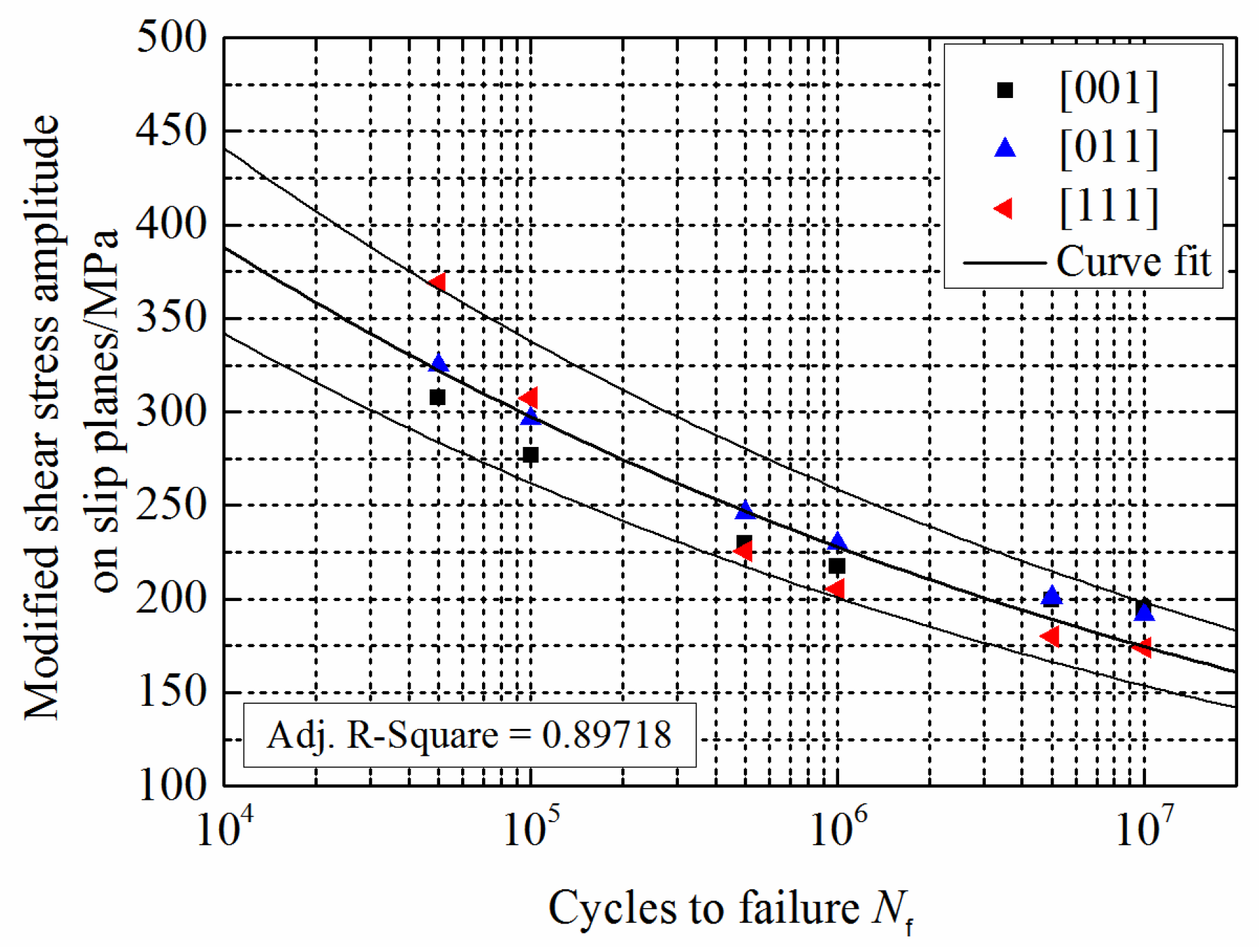
Figure 4.
Fatigue life predictions for DD6 material at 800 °C: (a) stress amplitude; (b) maximum resolved shear stress amplitude; (c) maximum resolved shear stress amplitude (primary octahedral slip system); (d) McD model; (e) Fin model; (f) CCB model.
Figure 4.
Fatigue life predictions for DD6 material at 800 °C: (a) stress amplitude; (b) maximum resolved shear stress amplitude; (c) maximum resolved shear stress amplitude (primary octahedral slip system); (d) McD model; (e) Fin model; (f) CCB model.


Figure 5.
Fatigue life prediction for DD6 material at 800 °C by the proposed model.

Figure 6.
Fatigue life predictions for PWA1480 material at 648 °C: (a) stress amplitude; (b) maximum resolved shear stress amplitude; (c) maximum resolved shear stress amplitude (primary octahedral slip system); (d) McD model; (e) Fin model; (f) CCB model.
Figure 6.
Fatigue life predictions for PWA1480 material at 648 °C: (a) stress amplitude; (b) maximum resolved shear stress amplitude; (c) maximum resolved shear stress amplitude (primary octahedral slip system); (d) McD model; (e) Fin model; (f) CCB model.
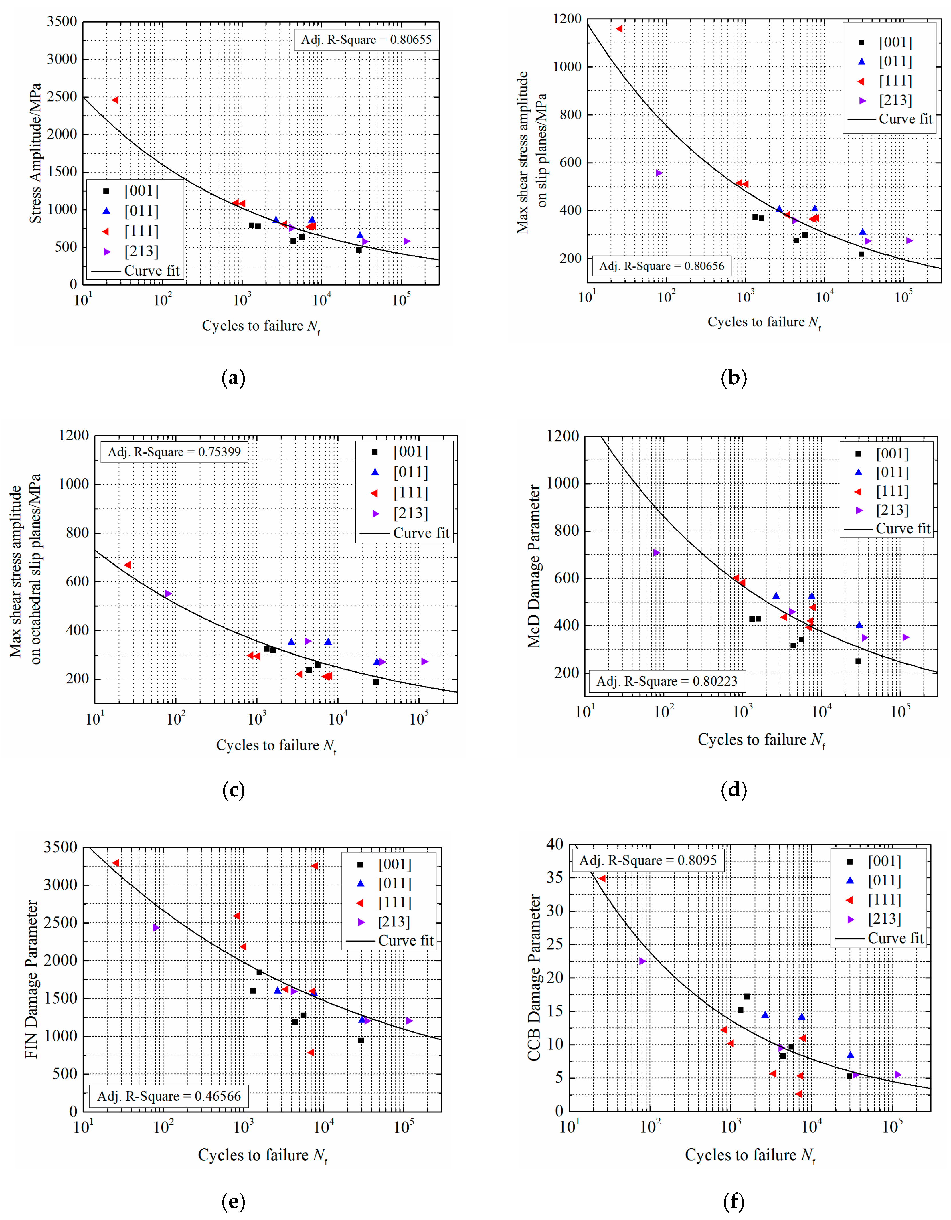
Figure 7.
Fatigue life prediction for PWA1480 material at 648 °C using the proposed model.

Figure 8.
Fatigue life predictions for PWA1484 material at 593 °C: (a) stress amplitude; (b) maximum resolved shear stress amplitude; (c) maximum resolved shear stress amplitude (primary octahedral slip system); (d) McD model; (e) Fin model; (f) CCB model.
Figure 8.
Fatigue life predictions for PWA1484 material at 593 °C: (a) stress amplitude; (b) maximum resolved shear stress amplitude; (c) maximum resolved shear stress amplitude (primary octahedral slip system); (d) McD model; (e) Fin model; (f) CCB model.

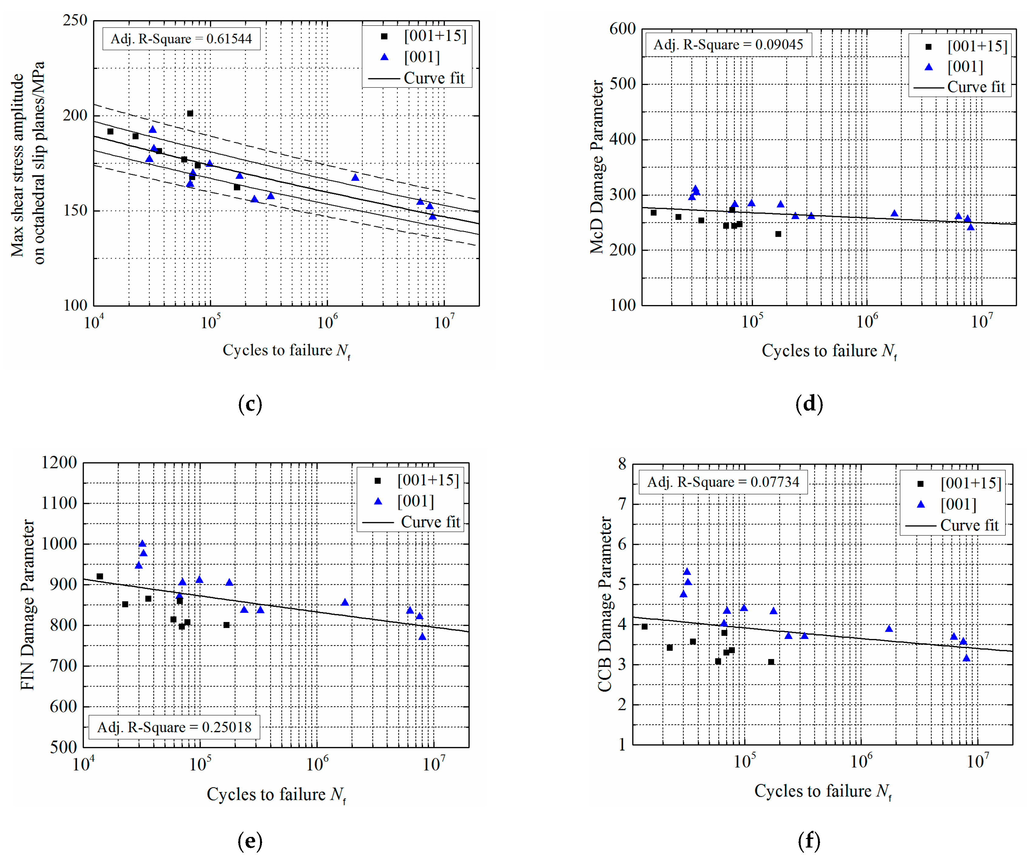
Figure 9.
Fatigue life prediction for PWA1484 material at 593 °C using the proposed model.


Table 1.
Direction cosines between coordinate axes in the different coordinate systems.
| Direction Cosines | Material CSYS | ||
|---|---|---|---|
| x | y | z | |
| x’ | l1 | m1 | n1 |
| y’ | l2 | m2 | n2 |
| z’ | l3 | m3 | n3 |
Table 2.
Direction cosines between the two coordinate systems.
| Direction Cosines | x | y | z |
|---|---|---|---|
| x’ | l11 | l12 | l13 |
| y’ | l21 | l22 | l23 |
| z’ | l31 | l32 | l33 |
| (1) Maximum resolved shear stress amplitude | |
| (2) Maximum resolved shear stress amplitude (primary octahedral slip system) | |
| (3) Maximum resolved shear strain amplitude | |
| (4) Maximum resolved shear strain amplitude (primary octahedral slip system) | |
| (5) Maximum shear stress range | |
| (6) Chu-Conle-Bonnen (CCB) model | |
| (7) Findley (Fin) model | |
| (8) McDiarmid (McD) model |
Table 4.
Material properties.
| Material Properties | DD6 (700 °C) | DD6 (800 °C) | PWA1480 (648 °C) | PWA1484 (593 °C) |
|---|---|---|---|---|
| E/GPa | 107.0 | 102.2 | 106.2 | 108.2 |
| G/GPa | 100.2 | 85.3 | 108.3 | 109.8 |
| ν | 0.3740 | 0.3797 | 0.4009 | 0.3995 |
Table 5.
Nickel-based single crystal fatigue life prediction models.
| (1) | With maximum resolved shear stress amplitude of the 30 slip systems as the damage parameter, all of the fatigue life prediction results are good. |
| (2) | With maximum resolved shear stress amplitude of the primary octahedral slip system as the damage parameter, all of the fatigue life prediction results are worse. |
| (3) , (4) | Models with resolved shear strain amplitude as the damage parameter generally have poor prediction results for nickel-based single crystal materials. |
| (5) | The fatigue life prediction model with stress amplitude or maximum shear stress as the damage parameter has a higher life prediction accuracy. |
| (6) CCB | Life prediction results obtained by using the CCB model for PWA1480 low cycle fatigue data are better, while the life prediction results of the CCB model for DD6 high cycle fatigue data are worse. |
| (7) Fin | Life prediction results for DD6 high cycle fatigue data obtained using the Fin model are better, while those for PWA1480 low cycle fatigue data obtained using the Fin model are worse. |
| (8) McD | The McD model has a higher life prediction accuracy. |
| (9) | The nickel-based single crystal fatigue life prediction model based on modified resolved shear stress amplitude, which has been proposed in this paper, has higher life prediction accuracy. |
© 2019 by the authors. Licensee MDPI, Basel, Switzerland. This article is an open access article distributed under the terms and conditions of the Creative Commons Attribution (CC BY) license (http://creativecommons.org/licenses/by/4.0/).
Share and Cite
MDPI and ACS Style
Wang, J.; Wei, D.; Wang, Y.; Jiang, X. A Fatigue Life Prediction Model Based on Modified Resolved Shear Stress for Nickel-Based Single Crystal Superalloys. Metals 2019, 9, 180. https://doi.org/10.3390/met9020180
AMA Style
Wang J, Wei D, Wang Y, Jiang X. A Fatigue Life Prediction Model Based on Modified Resolved Shear Stress for Nickel-Based Single Crystal Superalloys. Metals. 2019; 9(2):180. https://doi.org/10.3390/met9020180
Chicago/Turabian StyleWang, Jialiang, Dasheng Wei, Yanrong Wang, and Xianghua Jiang. 2019. "A Fatigue Life Prediction Model Based on Modified Resolved Shear Stress for Nickel-Based Single Crystal Superalloys" Metals 9, no. 2: 180. https://doi.org/10.3390/met9020180
Note that from the first issue of 2016, this journal uses article numbers instead of page numbers. See further details here.