Analysis of the Influence of Segmented Rollers on Slab Bulge Deformation


School of Mechanical Engineering, University of Science and Technology Beijing, Beijing 100083, China
*
Author to whom correspondence should be addressed.
Metals 2019, 9(2), 231; https://doi.org/10.3390/met9020231
Submission received: 26 December 2018
/
Revised: 10 February 2019
/
Accepted: 12 February 2019
/
Published: 14 February 2019
(This article belongs to the Special Issue Continuous Casting)
Abstract
:The bulge deformation of the continuous casting slab must be controlled in order to improve the slab quality. In this study, a coupled three-dimensional thermomechanical model is suggested based on dynamic contact between the slab and the rollers, so as to investigate the influence of the rollers in reducing slab bulge deformation. Moreover, the rigid casting rollers in this model are replaced by elastic casting rollers in order to improve the calculation accuracy. Further, the influence of two-segment and three-segment rollers on the slab bulge deformation is systematically studied. The results indicate that the bulge deformation of the slab increased by 74.3% when elastic casting rollers were adopted instead of rigid casting rollers. This deformation was reduced by 29.7% when three-segment rollers were used instead of two-segment rollers. Moreover, the influence of the roller spacing and the roller diameter of the segmented roller on the deformation was studied in detail. In order to achieve the purpose of controlling the bulge deformation, improved segmented roller spacing and diameter were proposed, leading to a 75.4% reduction in the bulge deformation.
1. Introduction
It is important to effectively control bulge deformation to improve the quality of continuous casting slabs. Thermal creep is one of the main factors that can cause bulge deformation in slabs, as the temperature distribution of the slab on both the wide and narrow sides affects bulge deformation. It is necessary to obtain the temperature field of a continuous casting slab during the solidification process. Some scholars have developed a two-dimensional solidification model to obtain the temperature field distribution of the slab during continuous casting [1,2]. However, they neglected the temperature field distribution of the wide sides. The two-dimensional solidification model was replaced by a three-dimensional solidification model to analyze the slab temperature field because the temperature distribution of the slab on both the wide and narrow sides could be considered in the three-dimensional model [3,4], which could better match the actual solidification process in continuous casting. This deformation calculation is very complicated. Some scholars used the theoretical analysis method [5,6,7,8] and two-dimensional thermomechanical coupling models to calculate bulge deformation [9,10]. However, the calculation accuracy of the theoretical analysis method could not be guaranteed because the bulge deformation and temperature fluctuations on the wide side of the slab in the two-dimensional model were neglected. Therefore, three-dimensional models of slab bulge deformation were developed to improve the calculation accuracy. A three-dimensional elastic–plastic and creep model was developed to calculate the slab bulge deformation on the wide side [11,12,13]. This model considered static contact between the continuous casting slab and the rollers. However, this model neglected the movement of the slab under the casting rollers.
In order to consider the dynamic contact between the slab and the rollers, Qin et al. suggested a 3D thermomechanical coupling model based on this dynamic contact between the slab and the rollers to compare with the 2D bulge deformation model to calculate bulge deformation [14]. Thus, Liu et al. proposed a 3D finite element viscoelastic creep model to study slab bulge deformation and the influence of temperature field distribution on this deformation [15]. However, this model neglected the slab bulge deformation on the narrow side. The slab bulge deformation on the wide side and that on the narrow side are actually mutually influential, and bulge deformation on the wide and narrow sides has been observed by some scholars [16,17,18]. Thus, 3D thermomechanical coupling models that included the dynamic contacts between the slab and the rollers were established to study the slab bulge deformation of the narrow side [19,20]. The 3D finite element models mentioned above mainly focused on the deformation mechanism of bulge deformation and the influence of process and structural parameters on this deformation. However, control measures of bulge deformation were hardly used in these models.
Qin et al. built a three-dimensional thermomechanical coupling model to study the temperature and bulge deformation distributions of a slab during the casting process, and the bulge deformation of this model was compared with that of the 2D bulging model [13,18]. The simulation results in the 3D bulging models were further compared with measured data from the actual production process to explore the accuracy of the simulation results in the three-dimensional bulge deformation models [17,20]. This comparison made it possible to use the finite element method to explore a method for controlling slab bulge deformation, and the fixed-gap and variable-diameter methods were suggested to reduce bulge deformation [21,22,23,24].
In the above-mentioned models, all casting rollers were assumed to be rigid, in order to save computing time, and the influence of casting roller deformation on slab bulge deformation was neglected. In fact, these casting rollers also deform during continuous casting. Therefore, this simplification would lead to an inaccurate reduction of bulge deformation values for a continuous casting slab. Moreover, segmented rollers have been widely adopted in the actual production process to control for slab bulge deformation [25,26,27]. The reason for this is that the stiffness of segmented rollers is much greater than that of solid rollers [28,29]. However, the structural parameters of segmented rollers have not been systematically studied for controlling slab bulge deformation.
This paper aims to discover the influence of segmented rollers on reducing slab bulge deformation and investigate the relationship between the stiffness of the segmented rollers and slab bulge deformation. A 3D thermomechanical coupling model based on the dynamic contact between the slab and the elastic casting rollers was suggested, and the structural parameters of the segmented rollers are investigated for controlling bulge deformation.
2. 3D Solidification Model Description
The temperature distribution is the foundation of this bulging analysis because the thickness of the solidified slab and the material property parameters depend on the temperature field in the slab. Therefore, the first step was to obtain the temperature field by using a solidification model.
2.1. 3D Solidification Finite Element Model
The cooling process of the continuous casting slab was a three-dimensional transient heat transfer process with heat conduction, thermal convection, and thermal radiation accompanied by phase transition. The heat transfer differential equation can be expressed as [30]:
The axial position along the liquid level of crystallizer is related to casting speed and time . The relation function is . The relation function is substituted into Equation (1) and Equation (2) is shown as follows:
where
- is the density (),
- is the specific heat capacity under constant pressure (),
- is the temperature (),
- is time (),
- is the internal heat source (),
- is the thermal conductivity (), and
- is the casting speed, ().
There is a solid phase zone, a liquid phase zone, and a two-phase zone in the continuous casting process, and Equation (1) can be treated as follows:
(1) The solid phase and liquid phase can be calculated as:
The heat transfer differential equation of the slab in the solid phase zone and the liquid phase zone is exactly the same Equation (3). The corresponding thermal conductivity can be obtained in the solid phase zone and the liquid phase zone separately.
For the thermal conductivity of the liquid phase zone, the forced convection heat transfer was caused due to the flow of the molten steel, which accelerated the elimination of the degree of superheat. In 1967, Mizikar [31] introduced the effective thermal conductivity for the first time to take the effects of convective heat transfer into account. The method was to treat the liquid phase zone of the slab into a "quasi-solid" and convert the convective thermal conductivity of the molten steel into an effective thermal conductivity, which was equivalent to times compared with the thermal conductivity of the static molten steel. The value of was generally from 2 to 7. Therefore, this method was used to calculate the thermal conductivity of the liquid phase zone in the paper and the value of was 5. The relationship between the thermal conductivity of the solid phase zone and the thermal conductivity of the liquid phase zone was as follows:
where
- is the thermal conductivity of the solid phase zone (), and
- is the thermal conductivity of the liquid phase zone ().
(2) Since the two-phase zone has the latent heat of solidification, the internal heat source in Equation (1) must be taken into consideration. In this study, the equivalent specific heat method was used to solve the latent heat of solidification and is calculated as:
where
- is latent heat of solidification under the action of various metals (),
- is the liquidus temperature (K), and
- is the solidus temperature (K).
Equation (5) was introduced in the solidification heat transfer differential equation of the two-phase zone and Equation (1) was rearranged as:
where is the equivalent heat capacity () and is calculated as:
is the thermal conductivity of the two-phase zone (), and is calculated as:
is the density of the two-phase zone ().
A half three-dimensional solidification finite element model was established due to the symmetry of the slab, and had dimensions of 1200 mm × 2000 mm × 250 mm. DC3D8 is an eight-node linear heat transfer hexahedral element in the ABAQUS software (6.14, Dassault Systèmes Simulia Corp., Providence, RI, USA) and was used to mesh the solidification model to perform thermal simulation analysis. The size of the element was 25 mm (length) × 25 mm (width) × 10 mm (height), and 46,080 heat transfer elements and 51,597 nodes were included in the model. The bulge deformation at the end of the foot roller section was investigated because the bulge deformation of the slab is serious when the slab leaves the foot roller section. Therefore, segmented rollers have been widely adopted to control this deformation. Then, the temperature field at the end of the foot roller section was studied for the analysis. The location of the segmented rollers and the final solidification point are listed in Figure 1.
2.2. Physical Property Parameters
The material of the slab analyzed in this paper was Q235, and the material that was measured in Xiangtan Iron & Steel Co., Ltd. of Hunan Valin was AH36. The compositions of Q235 and AH36 are shown in Table 1 and Table 2, respectively.
According to the actual production process of an arc continuous casting machine, the slab geometry of the model and physical property parameters were quoted from the references [31,32,33,34] and they are listed in Table 3 and shown in Figure 2. For this study, the cooling water heat transfer, the slab surface radiation, and the heat transfer between the rollers and the slab were defined as the equivalent convection coefficient; the convection heat transfer of molten steel was expressed by effective thermal conductivity; and the latent heat of solidification was calculated by using the equivalent specific heat method.
2.3. Boundary Conditions
(1) The comprehensive heat transfer coefficient was utilized to express the heat transfer process of the model, and the calculation expressions are as follows:
(a) The heat flux in the crystallizer was defined as follows:
where
- is determined by the actual heat balance calculation,
- is the crystallizer length (m), and
- is the casting speed ().
(b) The heat flux in the secondary cooling zone was determined as follows, and the secondary cooling zone was from the end of the crystallizer to the final solidification point:
where
- is the heat flux (),
- is the heat transfer coefficient (),
- is the slab surface temperature (), and
- is the cooling water temperature ().
(2) The initial temperature of the slab was uniformed as the inlet temperature of 1808 K.
2.4. Results and Discussion
The temperature and thickness distributions of the slab on the wide and narrow sides are shown in Figure 3. In this study, the simulation results were validated based on the actual slab temperature measurement results of the AH36 steel continuous casting process. The comparison of the measured and simulated temperatures in the center of the narrow face are exhibited in Figure 3b. As can be seen from this figure, the simulation temperature was close to the test temperature, and the maximum relative error was less than 5%. Thus, the simulation result that agreed well with the measured data could be used as the basis temperature field for bulge deformation analysis.
The temperature distributions on the wide and narrow sides are shown in Figure 3c,d. At the end of the foot roller section of the continuous slab caster, the highest temperature of the slab was 1276 K and the lowest temperature was 940 K on the wide side. The difference in temperature was 336 K, thus dropping by 26.3%. The highest temperature of the slab was 1400 K and the lowest temperature was 940 K on the narrow side. The difference in temperature was 460 K, a decrease of 32.9%. The thickness of the solidified slab at this segment was about 42.5 mm on the wide side, and the thickness of the narrow side was about 41 mm. Due to the uneven heat transfer, the temperature field of the slab was unevenly distributed overall. The lowest temperature of the slab appeared in the corner area owing to the bidirectional heat transfer characteristic.
3. The Establishment of the Bulge Deformation Model
The three-dimensional thermoelastic–plastic and creep coupling models were proposed to investigate slab bulge deformation after temperature distribution and the thickness of the solidified shell had been acquired. The relationship between the solidification heat transfer model and the slab bulge deformation model is illustrated in Figure 4. Q235 steel served as the analytical material of the casting slab. The casting roller material was 40CrMo.
3.1. Physical Property Parameters
In the high-temperature continuous casting process, the bulge deformation of the slab is not only determined by the thermal process, as the high-temperature mechanical properties of the material also have an important influence on the deformation behavior of the slab. In order to accurately analyze the deformation of the casting slab, it was necessary to clarify the high-temperature mechanical properties of Q235 steel. Physical property parameters of the slab were quoted from the references [35,36] and are shown in Figure 5. According to the investigation, the material parameters of 40CrMo at the temperature of 523 K were suitable for the bulge deformation model analysis. The elastic modulus was 189.46 MPa, the Poisson ratio was 0.28, and the density was 7850 kg∙m−3.
3.2. Geometric Model with Various Segmented Casting Rollers
The geometric parameters of the slab and casting rollers used in the model are listed in Table 4. The three-dimensional geometric models of the interaction between the slab and the various casting rollers are shown in Figure 6, including rigid solid rollers, elastic solid rollers, elastic two-segment rollers, and elastic three-segment rollers. C3D8R was the eight-node linear three-dimensional stress hexahedron reduction integral element which was used to build the models. The casting slab was composed of 20,400 elements (C3D8R) and 40,581 nodes. In the continuous casting process, it was assumed that the casting rollers were linearly distributed, ignoring the casting blank curvature. The liquid core of the slab was removed and simplified as a cavity, and the static pressure of the molten steel in the slab was transformed into a uniform pressure on the inner surface of the slab. During the analysis, the thickness of the casting slab and the distribution of the temperature field did not change with the operation of the slab.
3.3. Boundary Conditions and Contact Definition
(1) The uniform pressure was 369,634 Pa, which was to be the static pressure of the molten steel in the slab.
(2) The symmetrical displacement constraint was loaded on the slab because of the symmetry of the structure.
(3) When the longitudinal length of the slab was chosen as 2000 mm, the influence of the slab boundary on the internal structure could be neglected according to Saint-Venant’s principle, and the calculation accuracy and efficiency could be guaranteed.
3.4. Creep Model
It was found that the time-hardening model could describe the creep behavior of the metal with a carbon content of 0.18% and a secondary cooling temperature range of 1173 K~Ts [37]. This could satisfy the requirements of this paper. Therefore, the time-hardening model was used as the creep model of the casting slab material. The constitutive equation of the time-hardening model is shown as Equation (7):
where
- ,
- ,
- ,
- ,
- is the creep strain rate (),
- is the influence parameter of carbon content (),
- is the stress (MPa),
- is the deformation energy constant (),
- is the temperature (),
- is the time (),
- is the temperature-dependent time influence index, and
- is the temperature-dependent comprehensive stress influence index.
3.5. Predefined Temperature Field
The slab temperature distribution at the end of the foot roller section was introduced into the bulging analysis as a predefined field and kept invariable in the calculation process of bulge deformation.
4. Comparisons of Slab Bulge Deformations with Different Segment Rollers
The bulge deformation of the slab was obtained by establishing the three-dimensional finite element model of the coupling interaction between the various segmented rollers and the slab. The results calculated by ABAQUS were used to analyze the influence of the segmented rollers on slab bulge deformation.
4.1. Bulge Deformation on the Wide Side
The simulation results of slab bulge deformation along the wide side are shown in Figure 7. The influence of the segmented rollers was numerically analyzed by a comparison between the average values of the bulge deformation. As can be seen in Figure 7, the following conclusions can be drawn:
(1) In the bulge deformation model with the three-segment rollers, the deformation rapidly increased to 0.90 mm from the edge to the distance of 270 mm in the direction of the wide surface. The deformation of the slab formed into a bulging platform from the distance of 270 mm to the slab center (600 mm) in the wide direction. The value of the bulging platform was 0.90 mm. The reason for this was that the edge of the solidified slab had formed a thick shell of great stiffness, and the deformation was small. The thickness of the shell decreased with the increasing distance, resulting in the decrease of slab stiffness. The bulge deformation of the slab rapidly increased under the hydrostatic pressure. Then, the platform appeared with the uniform thickness and uniform static pressure of the slab. The deformation of the slab at the contact position with the roller sectional area was greater than the average value of the platform. This was because the fixed area of the slab intermittently passed through the sectional area of the segmented rollers, and the positive creep was more effective than the reverse creep in the fixed area. In the continuous casting process, the positive creep makes the solidified shell convex outwards, and the reverse creep makes the solidified shell recess.
(2) The minimum bulge deformation was 0.82 mm in the model with rigid solid rollers. The maximum bulge deformation of 1.43 mm appeared in the model with elastic solid rollers. The difference between the deformation of the two models was about 0.61 mm, and the increase remained around 74.3%. The results showed that the stiffness of the casting rollers had a great influence on slab bulge deformation. However, the casting rollers cannot be absolutely rigid rollers in the actual production process. Thus, the elastic rollers were more suitable than the rigid rollers to simulate the bulge deformation of the casting slab in the actual production process, as a more accurate result could be obtained.
(3) The two-segment and three-segment rollers were defined by using elasticity. The bulge deformation of the casting slab in the two-segment roller model was reduced to 1.28 mm in comparison with the elastic solid rollers model. The difference in bulge deformation was 0.15 mm, meaning there was a decrease of 10.5% between the two models, while the bulge deformation of the slab with the three-segment rollers reached 0.90 mm. The bulge deformation difference was 0.53 mm, dropping by 37.1%. The result indicated that the bulge deformation with the three-segment rollers was closer to that of the rigid solid rollers. This means that the bulge deformation of the casting slab could be effectively controlled by using segmented rollers, and the influence of the three-segment rollers was more effective than that of the two-segment rollers.
4.2. Bulge Deformation on the Narrow Side
The simulation result of the slab bulge deformation along the narrow side is displayed in Figure 8.
The horizontal bulge deformation of the slab’s narrow side was uneven, and the bulge deformation of the narrow side with the three-segment rollers was relatively close to that of the rigid rollers. The bulge deformation on the narrow side with the three-segment rollers reduced from 0.38 to 0.23 mm, a decrease of 39.5%. The bulge deformation on the narrow side with the two-segment rollers reduced from 0.39 to −0.008 mm, which was down by 102%. The bulge deformation on the narrow side with the rigid solid rollers reduced from 0.39 to 0.25 mm, dropping by 35.9%. The bulge deformation on the narrow side with the elastic solid rollers reduced from 0.37 to −0.08 mm, a decrease of 121.6%.
4.3. Analysis of Segmented Roller’s Stiffness
The stiffness of the casting roller was an important factor affecting slab bulge deformation. In the bulging models, the vertical displacement of the elastic casting roller had occurred, which was selected to measure the stiffness of the casting roller. The results are shown in Figure 9. The vertical displacement of the elastic solid roller was a reverse parabola distribution. The maximum value of 0.14 mm appeared in the center of the solid roller. The rigid roller was not deformed, so the vertical displacement was 0 mm. The vertical displacement of the two-segment roller was evenly distributed around 0.004 mm. The displacement of the three-segment roller in the vertical direction was generally distributed around 0.0015 mm. The average vertical displacement of the roller was selected for comparison to intuitively analyze the stiffness of the casting rollers. The average vertical displacement of the elastic solid roller was 0.07 mm, the average vertical displacement of the two-segment roller was 0.004 mm, and that of the three-segment roller was 0.0015 mm. The stiffness of the two-segment roller was 17.5 times greater than that of the solid roller, and the stiffness of the three-segment roller was 46.7 times greater than that of the solid roller. As the number of sections increased, the deflection of the segment roller during the continuous casting process was smaller. This indicated that the stiffness of the segmented roller was effectively improved. Combined with the previous analysis of casting slab deformation, the conclusion could be drawn that the stiffness of the segmented roller could be better improved than that of the solid casting roller, and the bulge deformation of the slab could also be excellently reduced.
5. Influences of Roller Spacing and Roller Diameter on Slab Bulge Deformation
5.1. Establishment of Deformation Model with Different Roller Spacings and Diameters
In the continuous casting process, bulge deformation must be controlled to ensure the quality of the slab. There are many factors involved in slab bulge deformation in continuous casting production, among which the main parameters include casting speed, static pressure of molten steel, shell thickness, roller spacing, roller diameter, and surface temperature of the slab. The main purpose of this section is to explore and analyze the influence of the segmented roller structure parameters on bulge deformation. Under a constant casting speed condition (1.5 m∙min−1), the bulge deformation was calculated and analyzed for the casting slab. The specific simulation structural parameters are shown in Table 5. The influence of the casting process parameters was numerically analyzed by a comparison between the average values of the bulge deformation.
5.2. Results and Conclusions
5.2.1. Influences of Roller Spacing on Bulge Deformation
Roller spacing was adjusted by changing the gap between the rollers. Under the condition of constant casting speed (1.5 m∙min−1), the bulge deformation was calculated with 350 and 400 mm as the roller spacings. The average values of the bulge deformation were compared with that of a 300-mm roller spacing. The diameter of the roller was 230 mm. The results of slab bulge deformation on the wide side, shown in Figure 10 and Table 6, were established by the simulation model with different roller spacings. It could be concluded that the approximate distribution of the slab bulge deformation on the wide side would not change with a 50 mm increase of the roller spacing, and the improvement of the three-segment roller for bulge deformation was most obvious. However, the bulge deformation of the slab under the same continuous casting segmented roller increased greatly with the increase of the roller spacing. The maximum increment of bulging deformation was 67.1% under the rigid roller with the roller spacing changing from 300 to 350 mm. The maximum increment of bulge deformation under the elastic roller was 47.4%, with the roller spacing changing from 350 to 400 mm. The maximum increment of bulge deformation under the two-segment roller was 37.5%, with the roller spacing changing from 300 to 350 mm. The maximum increment of bulge deformation under the three-segment roller was 60.0%, with the roller spacing changing from 300 to 350 mm. The bulging increase was about the same for the rigid roller and the three-segment roller. This also proved that the effect of the three-segment roller was closest to that of the rigid roller on slab bulge deformation. The minimum increment was 32.9% under the elastic solid roller with the roller spacing changing from 300 to 350 mm.
An analysis of variance (Table 6) showed that the value of variance ratio was 158.45 under different roller spacings, which was larger than the critical value of variance ratio (the critical value was 5.14). The value of variance ratio was 35.38 under different segmented rollers, which was larger than the critical value of variance ratio (the critical value was 4.76). This indicated that different roller spacings and segmented rollers all have a significant effect on slab bulge deformation. Generally, the slab bulge deformation on the wide and narrow sides increased with the increasing roller spacing. This was because the area of the slab between the two rollers increased with the increasing roller spacing. The effect of static pressure increased in the solidified shell, which indirectly reduced its stiffness. As a result, the value of slab bulge deformation became larger as the roller spacing increased. This indicated that roller spacing also played an important role in bulge deformation of the casting slab.
5.2.2. Influences of Roller Diameter on Bulge Deformation
The influence of roller diameter was observed by using the deformation models under various roller diameters and a constant roller spacing. The roller spacing was defined as 300 mm. The roller diameters of the bulging model are shown in Table 5. The results of bulge deformation on the wide side under different roller diameters are listed in Table 7. It was found that the slab bulge deformation under the rigid rollers was almost unchanged with different roller diameters. This was because the rigid roller was established by a rigid body that did not reform in the continuous casting process, and the changing roller diameters had no influence on slab bulge deformation. The average deformation of the slab on the wide side decreased by about 0.08 mm when the elastic solid roller diameter increased by 20 mm. The influence of changing roller diameters on bulging deformation was relatively small due to the low stiffness of the elastic solid roller. However, the slab bulge deformation was effectively influenced by changing the segmented roller diameter by 20 mm, including the two-segment and three-segment rollers. The maximum reduction of bulging deformation was 0.24 mm, with the two-segment roller diameter changing from 250 to 270 mm, and the decrease remained around 21.8%. The minimum reduction was 0.1 mm with the three-segment roller diameter changing from 230 to 250 mm, and the decrease remained around 11.1%. This was because the elastic roller was deformed in the model, which resulted in a larger contact area between the slab and the roller as the roller diameter increased. In other words, the rigidity of the solidified shell was indirectly increased. The bulge deformation of the continuous casting slab was effectively controlled with the improved stiffness of the solidified shell and the casting roller. An analysis of variance (Table 7) showed that the value of variance ratio was 6.30 under different roller diameters, which was larger than the critical value of variance ratio (the critical value was 5.14). The roller diameter had a significant effect on slab bulging deformation.
In general, the slab bulge deformation increased with the increased roller spacing and decreased with the increased roller diameter. The comparisons of average values of bulge deformation along the wide side are shown in Figure 11. When the roller spacing was 400 mm and the roller diameter was 230 mm, the maximum average value of bulge deformation along the wide side was 2.80 mm with the elastic solid rollers. When the roller spacing was 300 mm and the roller diameter was 270 mm, the minimum average value of bulge deformation along the wide side was 0.69 mm with the three-segment rollers; the difference was of 2.11 mm in comparison with the previous one. The bulge deformation was reduced by 75.4%. The optimized structural parameters could effectively control slab bulge deformation.
6. Discussion
Slab bulge deformation is an important factor that affects the quality of the slab. Most researchers have focused on the deformation mechanism of the slab and rarely explored an effective way to control slab bulge deformation. Also, rigid casting rollers were most commonly used in the slab bulging models in order to simplify the calculations of slab bulge deformation. Although this simplification could greatly reduce the model’s calculation time, the influence of roller deformation on slab deformation was neglected. In this paper, the influence of segmented rollers on slab bulge deformation was explored, and the structural parameters of segmented rollers were optimized to effectively control the bulge deformation of the casting slab. Also, elastic casting rollers were introduced to replace the traditional rigid casting rollers in the bulging model for simulation analysis to obtain more ideal results. The results showed that elastic casting rollers were more suitable for analyzing slab bulge deformation than rigid casting rollers. Then, by comparing the slab bulge deformation under the segmented and solid rollers separately, it was found that the stiffness of the segmented rollers was greater than that of the solid rollers, so that the bulge deformation of the slab could be effectively controlled. Finally, the roller spacing and diameter of the segmented rollers were further studied. It was found that reducing the segmented roller spacing and increasing the roller diameter could effectively control the bulge deformation of the slab. The research results in this paper could provide an effective theoretical basis for controlling slab bulge deformation in actual production.
7. Conclusions
A 3D finite element thermomechanical coupling model between segmented rollers and a casting slab was established to investigate the influence of the segmented rollers on slab bulge deformation. The traditional rigid continuous casting rollers were replaced by elastic continuous casting rollers in these models, which is an advantage that this model has over traditional models. The main conclusions are as follows:
(1) The slab bulge deformation under the elastic rollers increased by around 74.3% compared with that of traditional rigid rollers. The results indicated that the stiffness of the casting rollers would have a great influence on slab bulge deformation and the elastic rollers were more suitable for the slab bulge deformation analysis.
(2) The slab bulge deformation was 1.43 mm under the elastic solid rollers and was reduced by 10.5% under the two-segment rollers compared with elastic solid rollers, while the slab bulge deformation dropped by 37.1% under the three-segment rollers.
(3) The results showed that the bulge deformation could be controlled by reducing the roller spacing or increasing the roller diameter. The slab bulge deformation on the wide side increased when the roller spacing increased by 50 mm, with the maximum increase of 67.1% and the minimum increase of 32.9%. The average value of the slab bulge deformation was reduced by about 15% when the roller diameter was increased by 20 mm.
(4) The bulge deformation on the wide side was reduced by 75.4% when the roller diameter and spacing of the segmented rollers were optimized. This result indicates that the optimized structural parameters of casting segmented rollers could effectively control slab bulge deformation.
Author Contributions
Conceptualization, Q.Q.; methodology, Q.Q.; formal analysis, Q.Q.; investigation, M.L. and J.H.; writing—original draft preparation, M.L.; writing—review and editing, Q.Q.; visualization, M.L.; supervision, Q.Q.; funding acquisition, Q.Q.
Funding
This research was funded by the National Natural Science Foundation of China, grant number: 51375041.
Conflicts of Interest
The authors declare no conflict of interest.
References
- Janik, M.; Dyja, H.; Berski, S.; Banaszek, G. Two-dimensional thermomechanical analysis of continuous casting process. J. Mater. Process. Technol. 2004, 153, 578–582. [Google Scholar] [CrossRef]
- Ji, C.; Luo, S.; Zhu, M.; Sahai, Y. Uneven solidification during wide-thick slab continuous casting process and its influence on soft reduction zone. ISIJ Int. 2014, 54, 103–111. [Google Scholar] [CrossRef]
- Dong, Q.; Zhang, J.; Yin, Y.; Wang, B. Three-dimensional numerical modeling of macrosegregation in continuously cast billets. Metals 2017, 7, 209. [Google Scholar] [CrossRef]
- Long, M.; Chen, H.; Chen, D.; Yu, S.; Liang, B.; Duan, H. A combined hybrid 3-D/2-D model for flow and solidification prediction during slab continuous casting. Metals 2018, 8, 182. [Google Scholar] [CrossRef]
- Yoshii, A.; Kihara, S. Analysis of bulging in continuously cast slabs by bending theory of continuous beam. Trans. Iron Steel Inst. Jpn. 1986, 26, 891–894. [Google Scholar] [CrossRef]
- Liu, W.; Dai, Y. Study on the deformation of the liquid core continuous casting shell. Heavy Mach. 1994, 10–16. [Google Scholar] [CrossRef]
- Sun, J.; Sheng, Y.; Zhang, X. Analysis of bulging deformation and stress in continuous cast slabs. J. Iron Steel Res. 1996, 11–15. [Google Scholar] [CrossRef]
- Xu, R. Behavior analysis of bulging deformation in slab casting process. Heavy Mach. 2012, 17–21. [Google Scholar] [CrossRef]
- Toishi, K.; Miki, Y. Generation mechanism of unsteady bulging in continuous casting-2-fem simulation for generation mechanism of unsteady bulging. ISIJ Int. 2016, 56, 1764–1769. [Google Scholar] [CrossRef]
- Ha, J.; Cho, J.; Lee, B.; Ha, M. Numerical analysis of secondary cooling and bulging in the continuous casting of slabs. J. Mater. Process. Technol. 2001, 113, 257–261. [Google Scholar] [CrossRef]
- Zhang, Y. Analysis of solidification heat transfer and bulging in the cast slab. Master’s Thesis, Yanshan University, Hebei, China, 2011. [Google Scholar]
- Okamura, K.; Kawashima, H. Three-dimensional elasto-plastic and creep analysis of bulging in continuously cast slabs. Tetsu-to-Hagane 1989, 75, 1905–1912. [Google Scholar] [CrossRef]
- Ning, Z.; Wu, D.; Qin, Q.; Zang, Y. Three-dimensional emulation research on the bulging deformation during continuously casting slab. Metall. Equip. 2007, 2. [Google Scholar]
- Qin, Q.; Shang, S.; Wu, D.; Zang, Y. Comparative analysis of bulge deformation between 2D and 3D finite element models. Adv. Mech. Eng. 2014, 6, 942719. [Google Scholar] [CrossRef]
- Liu, H.; Zhang, X.; Qian, L. 3D Finite element calculation of creep bulging system development and application. Contin. Cast. 2015, 40, 54–58. [Google Scholar]
- Camporredondo, J.E.; Acosta, F.A.; Castillejos, A.H.; Gutierrez, E.P.; De la Gonzalez, R. Analysis of thin-slab casting by the compact-strip process: Part II. Effect of operating and design parameters on solidification and bulging. Metall. Mater. Trans. B 2004, 35, 561–573. [Google Scholar] [CrossRef]
- Zhang, J.; Shen, H.F.; Huang, T.Y. Finite element thermal-mechanical coupled analysis of strand bulging deformation in continuous casting. Adv. Mater. Res. 2011, 154–155, 1456–1461. [Google Scholar] [CrossRef]
- Qin, Q.; Yang, Z. Finite element simulation of bulge deformation for slab continuous casting. Int. J. Adv. Manuf. Technol. 2017, 93, 4357–4370. [Google Scholar] [CrossRef]
- Triolet, N.; Bobadilla, M.; Bellet, M.; Avedian, L.; Mabelly, P. A thermomechanical modelling of continuous casting to master steel slabs internal soundness and surface quality. Rev. De Métallurgie–Int. J. Metall. 2005, 102, 343–353. [Google Scholar] [CrossRef]
- Fu, J.-X.; Hwang, W.-S. Numerical simulation of slab broadening in continuous casting of steel. In Numerical Simulation-From Theory to Industry; InTech: Rijeka, Croatia, 2012. [Google Scholar]
- Li, B. Study about the High-temperature creep property of q460e steel and its bulging in continuous casting process. Master’s Thesis, Yan Shan University, Hebei, China, 2015. [Google Scholar]
- Han, P.; Ren, T.; Jin, X. Influence of roll misalignment on bulging of continuous casting slab. Iron Steel 2016, 51, 53–58. [Google Scholar]
- Ohno, H.; Miki, Y.; Nishizawa, Y. Generation mechanism of unsteady bulging in continuous casting-1-development of method for measurement of unsteady bulging in continuous casting. ISIJ Int. 2016, 56, 1758–1763. [Google Scholar] [CrossRef]
- Verma, R.; Girase, N. Comparison of different caster designs based on bulging, bending and misalignment strains in solidifying strand. Ironmak. Steelmak. 2006, 33, 471–476. [Google Scholar] [CrossRef]
- Yu, Y.; Duan, L.; Cui, X. Brief introduction of slab caster segment rollers. Metall. Equip. 2016, 45–48. [Google Scholar] [CrossRef]
- Li, S.; Shen, B. Roller type selection of sector of WISCO three steelmaking continuous casting machine. Metall. Equip. 1992, 14, 51–52. [Google Scholar]
- Shi, J. The advantages and theoretical argument of caster segment sub-section roller. In Proceedings of the 8th (2011) China Steel Annual Meeting, Beijing, China, 26 October 2011; p. 6. [Google Scholar]
- Liu, W.; Wang, W. Analysis on the stiffness of segmented baeking guide roll of slab continuous caster. Bao Steel Technol. 1994, 12, 58–63. [Google Scholar]
- Liu, W.; Wang, W. The influence of structure and classified number of backup guide rolls in CCM on the deformation of slab bulge. Shanghai Metals 1995, 17, 25–30. [Google Scholar]
- Qin, Q.; Wu, D. Thermal and Mechanical Behavior of Continuous Casting Equipment; Metallurgical Industry Press: Beijing, China, 2013. [Google Scholar]
- Mizikar, E.A. Mathematical heat transfer model for solidification of continuously cast steel slabs. Trans. Metall. Soc. AIME 1967, 239, 1747–1753. [Google Scholar]
- Cheng, J. Continuous Casting Steel Manual; Metallurgical Industry Press: Beijing, China, 1991. [Google Scholar]
- Feng, K.; Chen, D.; Xu, C.; Wen, L.; Dong, L. Effect of main thermo-physical parameters of steel Q 235 on accuracy of concasting transport model. Special Steel 2004, 25, 28–31. [Google Scholar]
- Mills, K.C.; Su, Y.; Li, Z.; Brooks, R.F. Equations for the calculation of the thermo-physical properties of stainless steel. ISIJ Int. 2004, 44, 1661–1668. [Google Scholar] [CrossRef]
- Fu, J.; Li, J.; Wang, C.; Zhu, J. Research of Young’s modulus of elasticity of steel Q235. Mater. Rev. 2009, 23, 68–70. [Google Scholar]
- Uehara, M. Mathematical modelling of the unbending of continuously cast steel slabs. Master’s Thesis, University of British Columbia, Vancouver, BC, Canada, 1983. [Google Scholar]
- Kozlowski, P.F.; Thomas, B.G.; Azzi, J.A.; Wang, H. Simple constitutive equations for steel at high temperature. Metall. Trans. A 1992, 23, 903. [Google Scholar] [CrossRef]
Figure 1.
Slab caster roller map.

Figure 2.
(a) Thermal conductivity of Q235 steel; (b) the specific heat of Q235 steel.
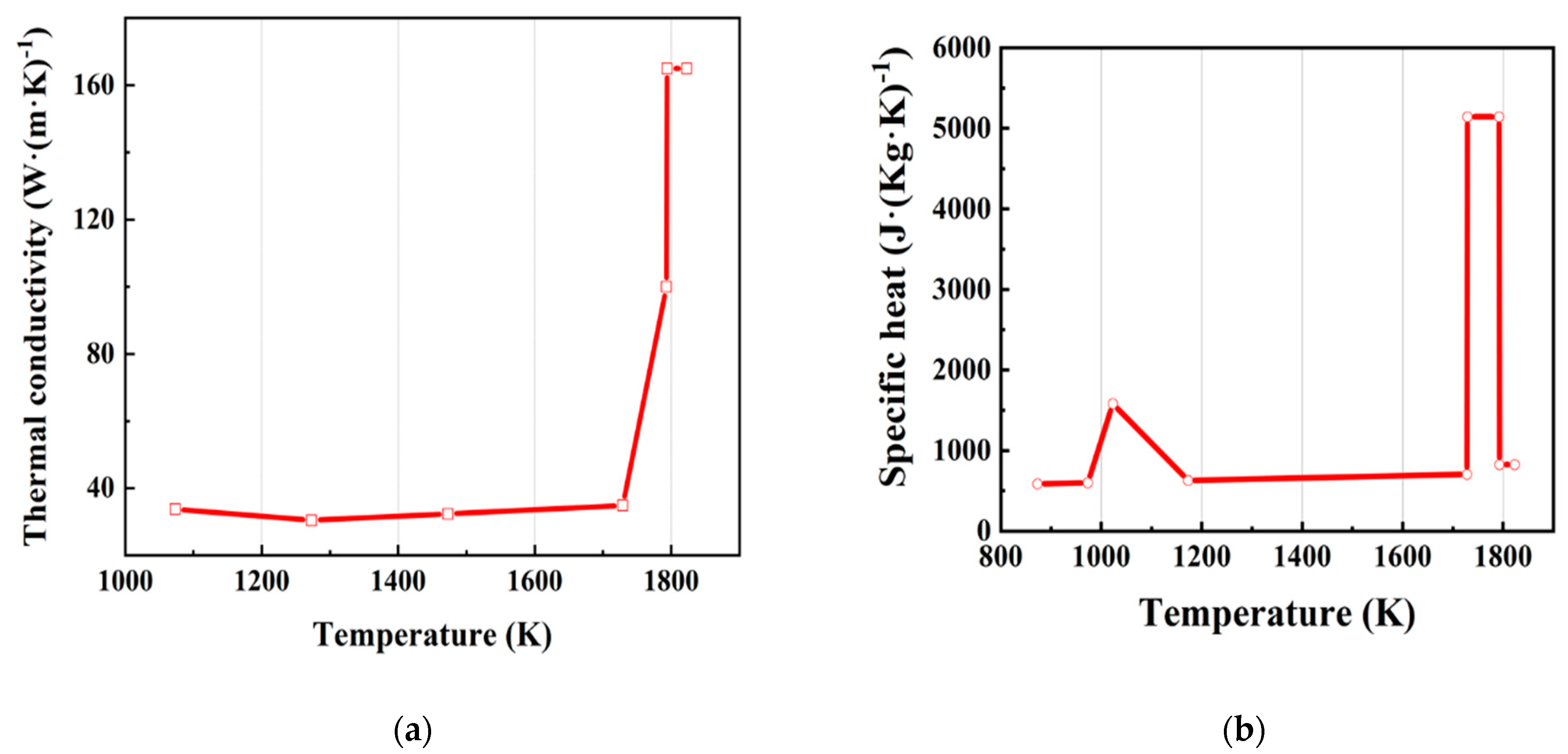
Figure 3.
(a) Temperature field of the model. (b) The comparison of the measured and simulated temperature in the center of the narrow face. (c) Temperature on the wide side. (d) Temperature on the narrow side.
Figure 3.
(a) Temperature field of the model. (b) The comparison of the measured and simulated temperature in the center of the narrow face. (c) Temperature on the wide side. (d) Temperature on the narrow side.

Figure 4.
The relationship between the solidification model and the slab deformation model.
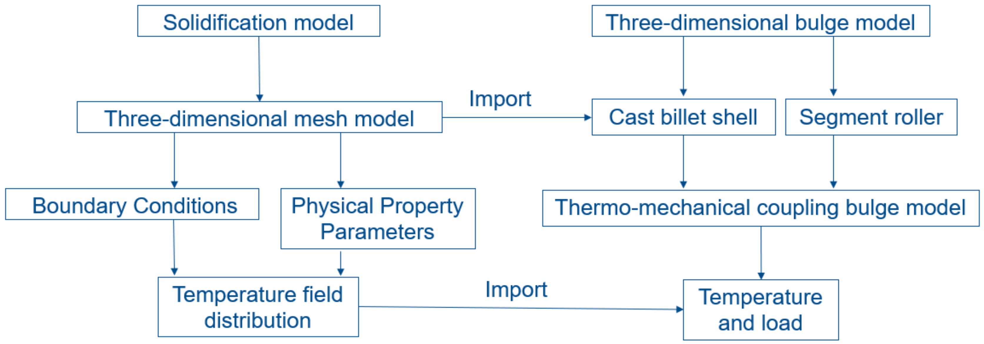
Figure 5.
(a) Elastic modulus of Q235 steel; (b) Poisson ratio of Q235 steel.
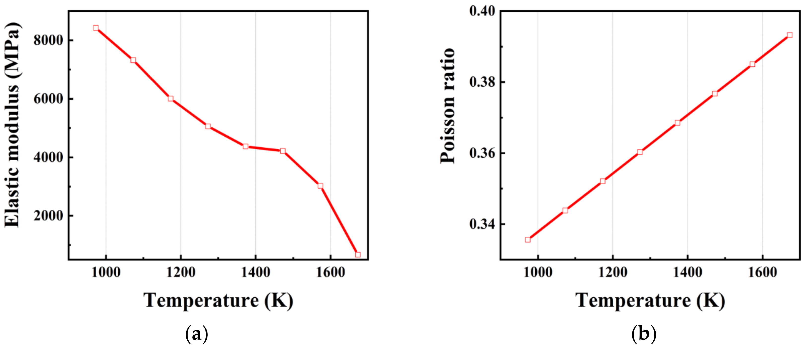
Figure 6.
(a) Bulging model with rigid solid rollers. (b) Bulging model with elastic solid rollers. (c) Bulging model with two-segment rollers. (d) Bulging model with three-segment rollers.
Figure 6.
(a) Bulging model with rigid solid rollers. (b) Bulging model with elastic solid rollers. (c) Bulging model with two-segment rollers. (d) Bulging model with three-segment rollers.

Figure 7.
Bulge deformation of the slab on the wide side with different casting rollers.

Figure 8.
Bulge deformation of the slab on the narrow side with different casting rollers.

Figure 9.
The vertical displacement of different casting rollers.

Figure 10.
The bulge deformation on the wide side with different roller spacings.

Figure 11.
Comparisons of slab bulge deformation with different segment roller structure parameters.
Figure 11.
Comparisons of slab bulge deformation with different segment roller structure parameters.


Table 1.
Chemical composition and content of Q235.
| Chemical Element | C | Si | Mn | P | S |
|---|---|---|---|---|---|
| Content (%) | 0.18 | 0.20 | 0.40 | ≤0.025 | ≤0.022 |
Table 2.
Chemical composition and content of AH36.
| Chemical Element | C | Si | Mn | P | S | Al | Cr | Cu | Ni |
|---|---|---|---|---|---|---|---|---|---|
| Content (%) | 0.157 | 0.2489 | 1.4143 | 0.0162 | 0.0044 | 0.0289 | 0.0375 | 0.0284 | 0.0177 |
Table 3.
Simulation constants for solidification analysis.
| Parameters | Values |
|---|---|
| Mold width | 1200 mm |
| Half slab thickness | 125 mm |
| Mold length | 2000 mm |
| Casting speed | 1.5 m∙min−1 |
| Water temperature | 303 K |
| Inlet temperature | 1808 K |
| Liquidus temperature | 1793 K |
| Solidus temperature | 1732 K |
| Specific heat capacity of the solid phase zone () | 706 |
| Specific heat capacity of the liquid phase zone () | 825 |
| Thermal conductivity of the solid phase zone () | 34.83 |
| Thermal conductivity of the liquid phase zone () | 165 |
| Latent heat of solidification under various metals () | 284 |
| Density | 7400 kg∙m−3 |
Table 4.
Simulation constants for bulge deformations.
| Parameters | Values |
|---|---|
| Thickness of the solidified slab on the wide side | 42.5 mm |
| Thickness of the solidified slab on the narrow side | 41 mm |
| Number of rollers | 15 |
| Roller spacing | 300 mm |
| Radius of roller | 115 mm |
| Length of roller | 1240 mm |
| Casting speed | 1.5 m∙min−1 |
Table 5.
Simulation parameters of bulging models.
| Roller Spacing | Rigid Roller | Elastic Roller | Two-Segment Roller | Three-Segment Roller |
|---|---|---|---|---|
| Roller Diameter | ||||
| 300 mm | 230 mm | 230 mm | 230 mm | 230 mm |
| 250 mm | 250 mm | 250 mm | 250 mm | |
| 270 mm | 270 mm | 270 mm | 270 mm | |
| 350 mm | 230 mm | 230 mm | 230 mm | 230 mm |
| 400 mm | 230 mm | 230 mm | 230 mm | 230 mm |
Table 6.
Bulge deformation on the wide side with different roller spacings.
| Roller Spacing | Rigid Roller | Elastic Roller | Two-Segment Roller | Three-Segment Roller |
|---|---|---|---|---|
| 300 mm | 0.82 mm | 1.43 mm | 1.28 mm | 0.90 mm |
| 350 mm | 1.37 mm | 1.90 mm | 1.76 mm | 1.44 mm |
| 400 mm | 1.93 mm | 2.80 mm | 2.38 mm | 1.96 mm |
Table 7.
Bulge deformation on the wide side with different roller diameters.
| Roller Diameter | Rigid Solid Roller | Elastic Solid Roller | Elastic Two-Segment Roller | Elastic Three-Segment Roller |
|---|---|---|---|---|
| 230 mm | 0.82 mm | 1.43 mm | 1.28 mm | 0.90 mm |
| 250 mm | 0.80 mm | 1.37 mm | 1.10 mm | 0.80 mm |
| 270 mm | 0.80 mm | 1.25 mm | 0.86 mm | 0.69 mm |
© 2019 by the authors. Licensee MDPI, Basel, Switzerland. This article is an open access article distributed under the terms and conditions of the Creative Commons Attribution (CC BY) license (http://creativecommons.org/licenses/by/4.0/).
Share and Cite
MDPI and ACS Style
Qin, Q.; Li, M.; Huang, J. Analysis of the Influence of Segmented Rollers on Slab Bulge Deformation. Metals 2019, 9, 231. https://doi.org/10.3390/met9020231
AMA Style
Qin Q, Li M, Huang J. Analysis of the Influence of Segmented Rollers on Slab Bulge Deformation. Metals. 2019; 9(2):231. https://doi.org/10.3390/met9020231
Chicago/Turabian StyleQin, Qin, Ming Li, and Jianlin Huang. 2019. "Analysis of the Influence of Segmented Rollers on Slab Bulge Deformation" Metals 9, no. 2: 231. https://doi.org/10.3390/met9020231
Note that from the first issue of 2016, this journal uses article numbers instead of page numbers. See further details here.