Evaluation of the Formability and Dimensional Accuracy Improvement of Ti6Al4V in Warm SPIF Processes
by
 ,
,
Jesús Andrés Naranjo
1,2, 
Valentín Miguel
1,2,*,
Alberto Martínez
2,
Juana Coello
1,2 and
María Carmen Manjabacas
1,2 1
Industrial Engineering School of Albacete, University of Castilla-La Mancha, 02071 Albacete, Spain
2
Regional Development Institute, Materials Science and Engineering, University of Castilla La Mancha, 02071 Albacete, Spain
*
Author to whom correspondence should be addressed.
Metals 2019, 9(3), 272; https://doi.org/10.3390/met9030272
Submission received: 1 February 2019
/
Revised: 20 February 2019
/
Accepted: 21 February 2019
/
Published: 26 February 2019
Abstract
:Single Point Incremental Forming (SPIF) has great potential as it can be easily implemented and the forming process does not require the use of dies. However, its application to high performance alloys such as Ti6Al4V has not been resolved due to its characteristic low formability. In the literature, studies on the warm SPIF process applied to this alloy report improved formability. However, in some of these studies the procedures used are complex and in others the surface finishes obtained are unsatisfactory. The present study proposes a methodology consisting of a simple heating device which permits working at moderate temperatures and quantifies the benefit of the temperature on the alloy formability, the forces acting during the process, and finally the dimensional precision of the parts produced. Working temperatures in the range of 300–400 °C significantly reduce forces, increase formability of the alloy, and substantially reduce springback. However, the springback values suggest the need for dimensional compensation at the design stage of products.

1. Introduction
Single Point Incremental Forming of sheet metal, SPIF, has great potential for use due to the enhanced formability it provides and the fact it can be performed using general purpose numerical control machines without the need to use dies [1]. The procedure was first developed in the 1960s by Leszak [2]. Since then, much research has been conducted on the process, especially with high formability materials such as aluminum and low carbon content steels. A number of variants have been proposed and reviews of this technological development have been published by Emmens et al. [3] and Behera et al. [4]. Nonetheless, the application of the process has certain limitations due to the low formability of certain alloys, higher execution time compared to conventional stamping processes and room for improvement in dimensional accuracy and surface finish. These drawbacks are under research to enable the application of this technology at an industrial level. Ambrogio et al. [5] studied the high-speed execution of the process. Hussain et al. [6] investigated improving the surface finish by applying lubricants and sheet coatings before executing the process.
SPIF enables the production of small batches, development of prototypes, and the economically competitive production of customized elements such as biomedical implants [7]. The literature has addressed the general biomedical applications of SPIF [8,9] and also a number of specific applications such as maxillofacial implants [10], clavicle implants [11], denture plates [12], and ankle supports [13]. It is precisely in this field that titanium alloys are of special interest due to their biocompatible characteristics. These types of alloys also have great potential in aeronautical applications. However, they have limited formability at room temperature [14], which prevents their use in conventional stamping and roll-forming processes and greatly limits their capacity for processing by means of SPIF. Several systems have been studied for executing heat-assisted SPIF processes in order to improve the formability of these alloys. Duflou et al. [15,16] and Götmann et al. [17,18] proposed a laser-assisted heating system located in the zone immediately before the zone of contact with the tool, which showed good results. However, this system is complex, which hinders its general industrial application. For the SPIF of mild steel, Fan et al. [19] proposed a Joule effect heating system by running an electric current from the tool to the blank holder through the sheet metal, which entails having to insulate the rest of the machinery. This system has been applied to Ti6Al4V [20,21], but controlling the temperature during the process is complex and the surface finishes obtained are unsatisfactory. Ambrogio et al. [22] optimized the possibilities of this process from the perspective of formability and surface finish. Amini and Ghaei [23] proposed a low-voltage variant of this system using an alternating current, making the system safer for the operator and reducing equipment costs, but with inadequate surface finishes. Another system used by some authors [24] to heat the sheet metal in the SPIF of AZ31 magnesium alloy consists of using band heaters mounted on the external surface of the fixture; this indirect heating system is energetically inefficient and might complicate the monitoring of the process in experimental applications. Ambrogio et al. [25] recently developed a system of localized heating by induction integrated with the movement of the tool, combined with a cryogenic cooling system, which is also technologically complex to perform. Other authors, such as Durante [26], generated heat by friction between the sheet metal and the tool, which rotates at a high speed, while the process was executed. Palumbo [27] combined the effect of tool rotation with an external heating system using electric bands. Broadly speaking, it can be said that systems using friction for heating generate low-quality surface finishes and deteriorate the parts and tools used in the process.
On the other hand, great advances in the Finite Element Method, FEM, simulation field have been related in literature to predict the influence of parameters and variables involved in SPIF on the evolution of the process. Most authors [28,29] use explicit type solvers due to their minor computing time, although some of them recommend employing implicit type solvers as they lead to obtaining more accurate results [30]. In this context, some research is being carried out with the aim of reducing the computing time in implicit procedures. Thus, other authors have used the Lagamine software based on a Lagrangian method developed expressly for this purpose [31,32,33,34]. In previous works [35], the authors of the present paper have demonstrated the viability of using FEM software of general purpose, as ANSYS Workbench® with an implicit solver, to simulate complete parts made by SPIF.
For analyzing the process by FEM, it is necessary to know the plastic behavior of the material when this is subjected to great deformations. For that, the prolongation of the tensile data further than the Ultimate Tensile Strength (UTS) by using typical equations as Hollomon´s, Swit´s or Vocé´s [36] has usually been considered. Other functions are also used, for example, Johnson-Cook´s [37], that is similar to those but that introduces some terms that consider the test velocity and temperature. Some authors are developing specific methods for determining the material behavior model further than the UTS point, as photographic techniques to determine the real section of the tensile test specimen [38] or reverse engineering methodologies [39,40]. In previous works [41,42], the authors of the present paper have proven that the Swift model is adequate to explain the plastic behavior of the Ti6Al4V alloy for the SPIF process and they have also evaluated the forces needed to that.
In the present work, the authors propose to study the SPIF of Ti6Al4V titanium alloy at moderate temperatures. To this end, a direct heating system was employed, using heat bands located in the internal cavity of an experimental blankholder, which could be easily implemented at an industrial level. The study evaluates the influence of the temperature on the capacity of the process, the forces acting in it, and the dimensional accuracy of the formed parts, contrasting the results with those obtained by FEM simulation.
2. Materials and Methods
2.1. Characterisation of the Material
A 0.8-mm thick Ti6Al4V alloy sheet was used. A mechanical characterization was conducted by means of tensile tests at room temperature, 150 °C, 300 °C, and 450 °C. For each temperature, the tests were performed at 0°, 45° and 90° in relation to the sheet rolling direction. The uniformity and stability of the temperature in each test sample were guaranteed as set out by ISO standards [43,44]. The anisotropy was determined for different rolling directions. Table 1 shows the results obtained for the mechanical properties and the anisotropy indices. The results for the different rolling directions were averaged according to the plasticity theory. Coefficients K and n correspond to the Swift´s behavior equation [36], which is considered suitable for the alloy under study [41].
2.2. SPIF Assays
The experimental tests were run in a Deckel Maho machining center, model DMC 835V with three different semi-spherical tools—a 10 mm-diameter wolframium carbide tool, a 12 mm-diameter wolframium carbide tool, and a 12 mm-diameter hardened steel X40CrMoV5-1 tool with a hardness of 60 HRc. A hollow frame was built to fasten the sheet and it was supported on sliding linear guides with load cells acting as stops at their ends to prevent displacements on the X- and Y-axes. Load cells allowed us to record the forces Fx and Fy on the horizontal axes. Finally, the complete structure described was supported on a load cell to register the vertical Fz forces. All the load cells were monitored by a data acquisition system that recorded the resultant forces every 0.2 s. An electric, suitably isolated mini-oven was specifically designed and fitted inside the support, see Figure 1A. The temperature was registered by means of two thermocouples, one situated in the center of the upper sheet face and the other situated in working area of the form to be executed, see Figure 1B.
Assays were conducted using the three tools described above at room temperature, 200 °C, 300 °C, and 400 °C, without lubrication, taking care to screw or fasten the sheet metal to the fixture once the sheet had reached a uniform temperature, thus avoiding thermal stress and/or deformation on the material during the heating process. The temperature was controlled by using an on-off controller. The range of temperatures was lower than +/−10 °C. For that purpose, the thermocouple located in the working area transmits the temperature to the controller continuously. In the time interval indicated the temperature was remained into the set point +/−10 °C. Moreover, all the screws were located in their nuts from the beginning, although the tightening of each one was carried out after, just before the test. Definitely, temperature was kept constant before and during the test.
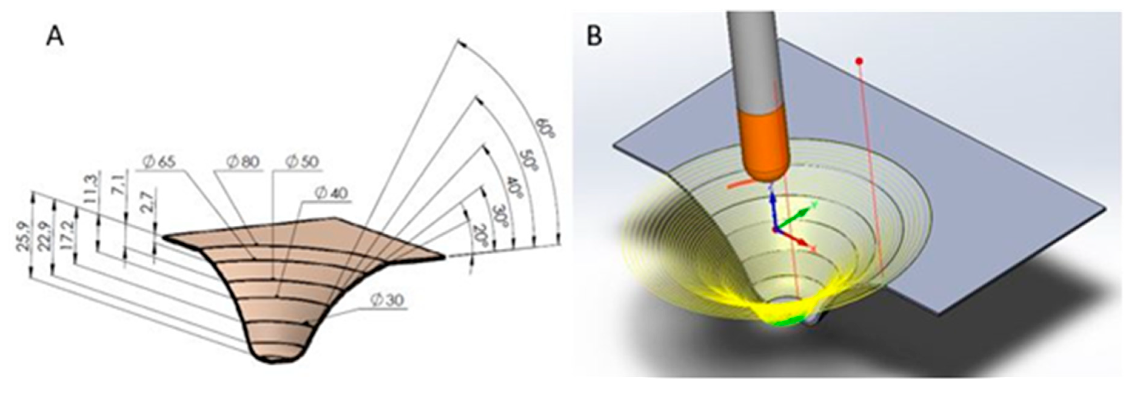
The forms executed were truncated cones with an outer diameter of 80 mm and either a constant or a variable wall angle, see Figure 2A. Table 2 shows the tests performed.
The forming strategy adopted was a helical path with a pitch of 0.5 mm per revolution and a feed rate of 600 mm/min, see Figure 2B. To minimize any friction between the tool and sheet, a counter-rotation speed of the tool was set at 30 rpm. Each test was repeated twice with the results showing good repeatability.
To evaluate the variation in the thickness of the sheet after the forming process, sectional cuts were made in different tested samples in the rolling direction by means of Electro Discharge Machining, EDM. Then they were evaluated dimensionally using a profile projector with a 1 µm resolution.
To measure the deformations in the main plane of the sheet, a 2 mm-mesh was generated on its surface using an inverted printing technique.
To evaluate the springback of the parts formed, the resultant geometry from the different assays was measured using a structured white light scanner (Smarttech, Warsow, Poland) with a 10 Mpixel-resolution, a 200 mm × 150 mm field of view, and 10 µm dimensional resolution. The results thus obtained were processed adequately to generate the sections at 0°, 45° and 90°, which, using a graphic design software, could then be compared to the theoretical or programmed shape of the part.
The forces on the tool on the X- and Y-axes were recorded, generating a maximum value for each rotation, which represents the radial force in the SPIF process, see Figure 3. The force values were the same on both axes, but lagged by 45° for obvious reasons.
2.3. FEM Simulation
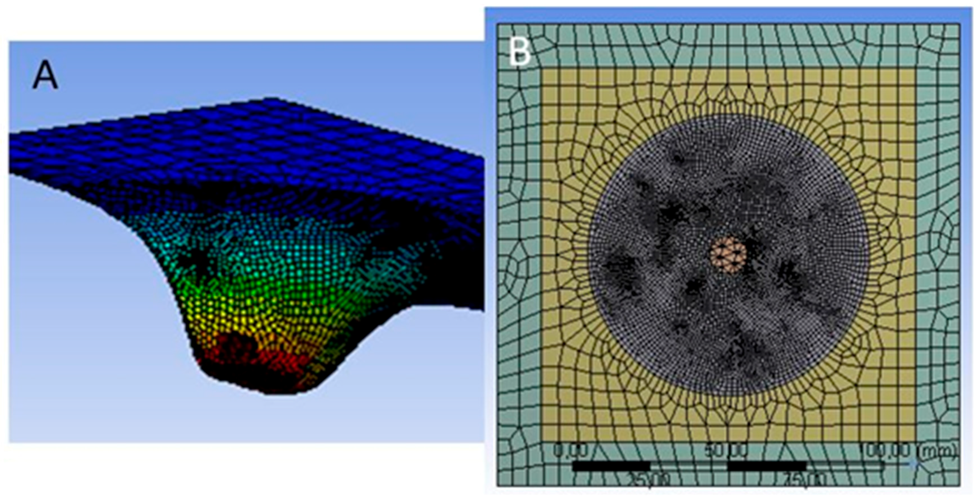
Test FEM simulations were carried out by ANSYS Workbench®, that is, a general purpose software package. According to the previous experience of some authors with respect to this simulation software [35,45] and with the ANSYS manual specifications [46], the option “transient structural” was selected. In this way, an implicit solver was used for solving the equations generated by FEM preprocess. A fixed support of the contact sheet-blankholder was defined for being modelled and the tool motion was introduced by the coordinates X, Y, and Z as a function of time. Two different mesh sizes were established: One of 6 mm length for non-critical zones that were not to be deformed; a 1 mm length mesh was defined for dividing the forming area in SPIF process, see Figure 4. The selected shape of the finite elements was “sweep”, as it generates hexahedral elements with 20 nodes each. The average total number of nodes and elements were 46705 and 6815, respectively, and the integration scheme was set up by default; ANSYS uses the implicit Newmark time integration method to solve the equations at discrete timepoints; this scheme converges at all steps. No symmetry treatment was done, as the tool path was helicoidal and the tool moves around the sheet. Due to the above described, CPU times were large and an average time of one week employing an I-7 µ-processor was necessary for each simulation. The contact tool-sheet was established with the sliding possibility of those elements between them. Coefficients of friction values of 0.35, 0.45, and 0.55 were adopted for the different temperatures of the SPIF process according to previous results of friction tests under similar conditions [47].
SPIF simulation was carried out solving the problem for a small displacement of the tool and taking the new state as the starting point of the next displacement. For achieving a balance between the results convergence and the computation time, an increment of time of 0.02 to 0.05 s from one to the next state was selected.
To define the plastic behavior of the material during the simulation, a specific Swift model for every temperature was input considering the specific parameters that corresponded to those, see Figure 5.
3. Results
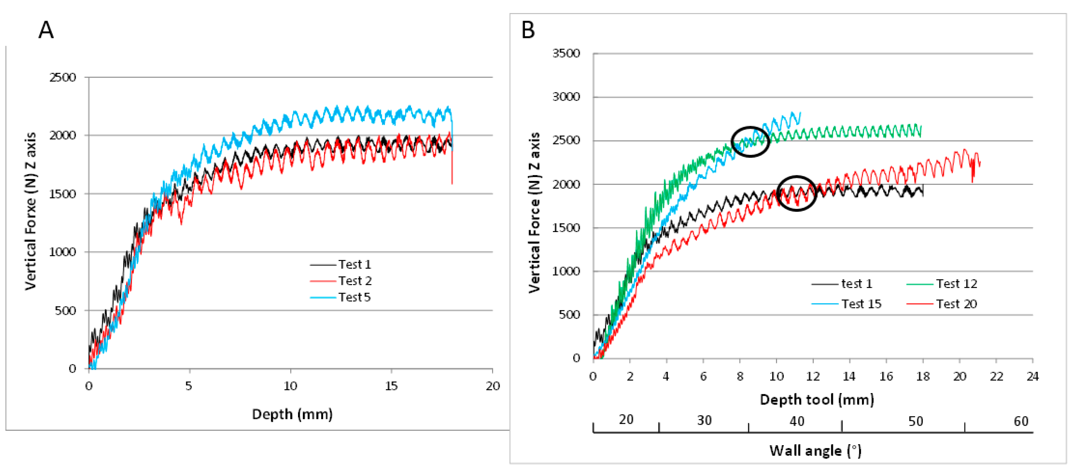
Table 2 shows the SPIF assays conducted on cones with constant and variable wall angles, indicating the conditions of each test, the results for the vertical forces required on the punch and the maximum depth achieved. For the cones with a constant wall angle, the force values correspond to the maximum stable force once the material reaches the plastic condition.
After every test, the measurement of the mesh mapped on the parts confirmed there was no dimensional variation in the circumferential direction, see Figure 6. This confirms the existence of plane deformation, as suggested by various authors [33].
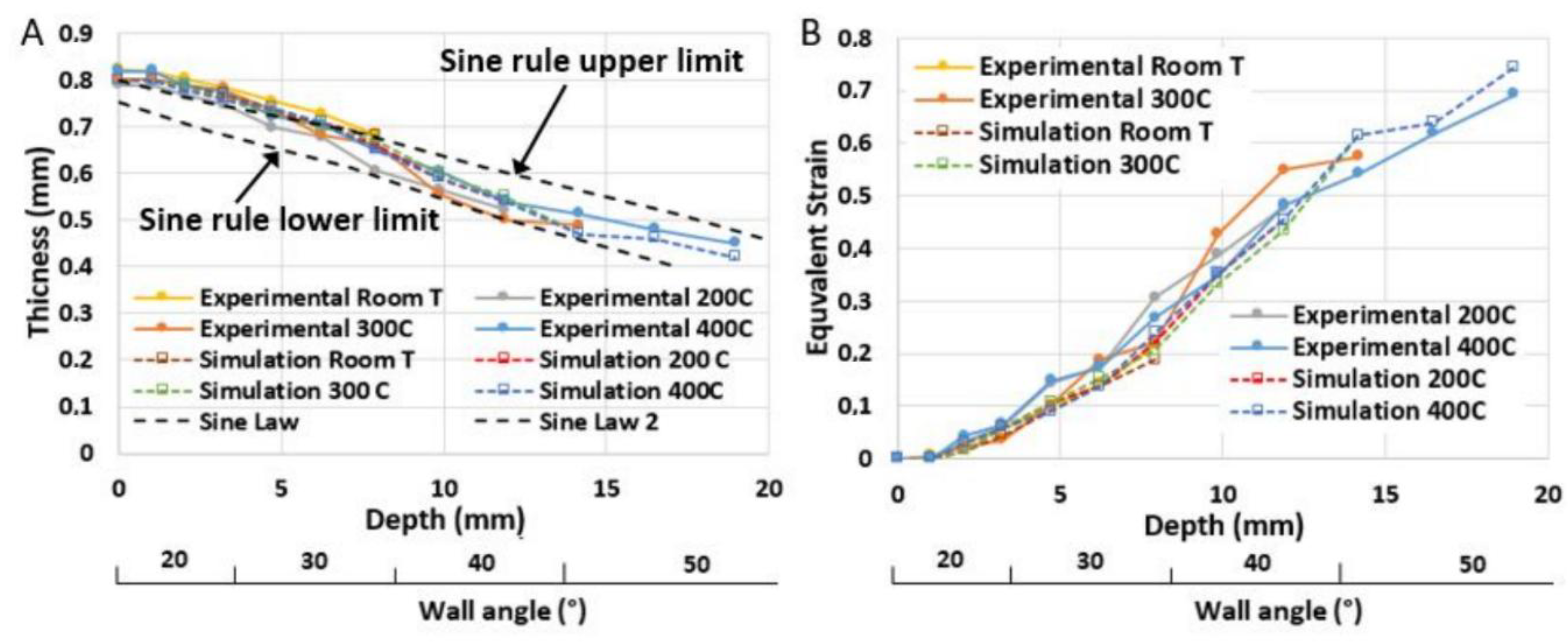
Although the thickness values could be deduced in light of the above, they were established using direct measurement as previously mentioned. Figure 7A shows the results obtained for different samples. The von Mises equivalent deformation, εeq, could also be calculated according to the evolution of the SPIF process, see Figure 7B. Thicknesses and equivalent strains were also obtained by FEM and the thrown values agreed in great rate with those achieved experimentally for all temperatures considered.
Figure 8 depicts the values of thickness worked out by FEM, and the experimental results obtained in different sections of the shape are indicated by means of the numbers included in the corresponding figures.
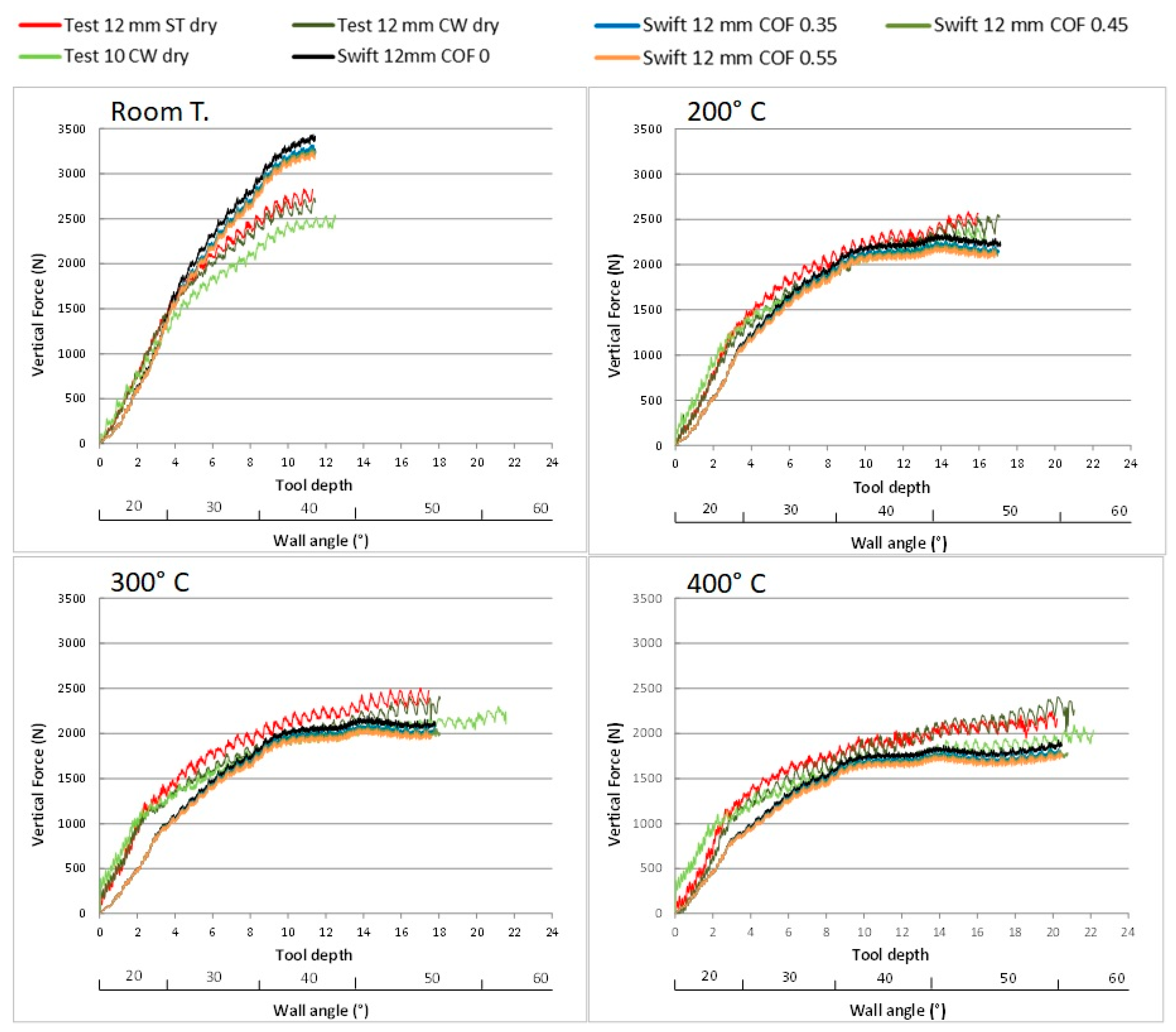
In Figure 9, the typical registers of the vertical forces that were measured in the SPIF tests it can be observed. Figure 10 shows the results corresponding to the forces recorded on the Z-axis for each tool at different temperatures in the variable wall angle assays. Figure 11 shows the force values observed in the direction of the main plane of the sheet, Fr, according to the assay depth using 12-mm steel and Wolframium Carbide WC tools. FEM simulation results have also been included in Figure 10 and Figure 11, taking into account different values for the coefficient of friction, COF.
The springback of the shapes formed by means of SPIF was evaluated taking as reference the depth that the part reached in each test. The elastic deformation was eliminated in FEM simulation as the force had ceased when the part is experimentally measured. The path programmed during the assay was compared with the results for the sections derived using a surface mesh obtained from the scanning of the parts, see Figure 12. To evaluate the springback, two parameters were defined to relate the phenomenon in radial direction, x, and in the depth of the part produced, ѱ. These parameters are defined in Equations (1) and (2) where h0 is the maximum depth reached by the tool in the assay, h1 is the depth measured after the assay, and d is the maximum distance between the programmed wall and that finally obtained in the part formed. The predicted shape by ANSYS is also depicted in Figure 12 for each SPIF test up to the break of the sheet. The experimental measurements were carried out once the sheet was released from the SPIF frame. The shapes predicted by ANSYS have also been included in Figure 12, but it should be emphasized that the hypothesis established in FEM analysis is that the part is fixed and logically the elastic recovery is not possible in the edge area of the sheet.
A theoretical analysis of stresses was carried out and Figure 13 depicts the stresses in the material at the end of the SPIF process considering that the shape was still fixed on the blankholder. Different temperatures were taken into account in the stress analysis.
4. Discussion
According to forces measured in the SPIF tests, Figure 14A shows a more detailed analysis of the influence of temperature in the process. Fz is represented depending on the SPIF wall angle and the temperature, taking the 12-mm WC tool as reference. In the analysis, Fz values were adjusted to a potential function, yielding high correlation indices, with the exception of the last section in each case. This is because the experimental results for the onset of fracture show little significance, mainly due to the short testing period for the wall angle corresponding to the angle in which a crack is incipient. Accordingly, it is observed that low heat, 200 °C for example, is significant in reducing hardening until plasticity, confirming the beneficial action of warm-SPIF compared to cold forming in the case of the Ti6Al4V alloy. Furthermore, as the temperature is increased, this effect is greater, although at temperatures above 300 °C the decrease in the slope is relatively limited, thus establishing this temperature as optimal. Moreover, the forming process is less complex to execute in these conditions than at higher temperatures. In Figure 14B the force is divided by the sheet thickness corresponding to the section processed, which, in comparative terms, corroborates the effect of the temperature on the forming force.
In relative terms, it is possible to calculate the decrease in force needed in the forming process as temperature increases. This is shown in Figure 15, in percentages with respect to the Fz values at room temperature. It can be observed that the decrease in forces is significant. Thus, the force required for a 40° wall angle is reduced by 20 to 30% depending on the temperature considered, from 200 °C to 400 °C.
Related to radial forces and Figure 11, the values obtained are around half of those of the vertical forces and directly correlate with the forming depth regardless of the wall angle (Figure 16 left). Figure 16 right shows the effect of the temperature on the forces on the main plane of the sheet.
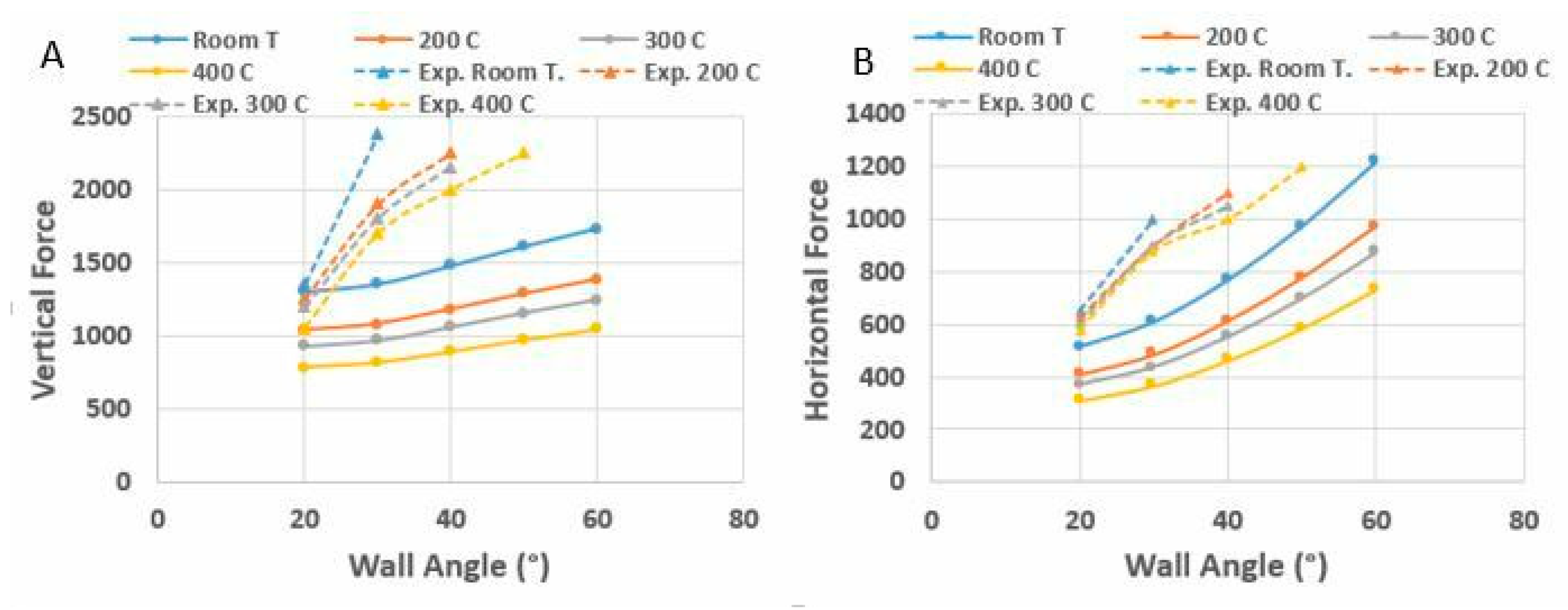
The relation between the experimentally obtained Fr and Fz values responds well to the analytical model initially proposed by Silva et al. [33] and subsequently developed by Lu et al. [48]. This was established by means of Equations (3) to (5), where t is the sheet thickness, rt is the tool radius, µ is the friction coefficient, Φ and θ are the components of the tool-sheet contact angle in the radial and circumferential direction respectively, Sc is the contact surface, Figure 17, and σeq is the equivalent material yield stress. However, the absolute experimental results do not fit the model. They are significantly higher than those which would be obtained analytically using the programmed geometry for the parts under study and considering a coefficient of friction in the range of 0.30–0.45 [47]. This may be explained if we take into account that the analytical equations are dependent on the tool-sheet contact, the formed wall angle, the friction coefficient, and the modelling used for the material behavior. The experimental contact surface is greater than the theoretical one due to the springback as the new deformation progresses, in both vertical and radial directions. Furthermore, the previously mentioned analytical models [33,48] establish a rigid-perfect plastic model as the hypothesis of material behavior, without hardening of the material. They also postulate the non-existence of mechanical effects related to bending or stress distribution as simplifying hypotheses, despite it having been demonstrated that in similar relations between forming tool radius and sheet thickness these effects are not insubstantial [40]. To enlighten these differences, the vertical and radial forces obtained by both procedures, experimentally and by the model above indicated, have been reported, see Figure 18.
Regarding springback (Figure 11), the phenomenon decreases notably in accordance with the forming temperature. Lower temperatures substantially enhance the springback response of the part. Finally, if we compare the results for the forming with constant and variable walls (Figure 12E,F) the springback values are similar for comparable angles. In any event, this type of analysis allows predictive criteria to be established for the progressive correction in the programming of parts in order to achieve the shapes required.
With respect the shape predicted by FEM, the great agreement found between the parts produced and the simulation results can be pointed out. Nevertheless, the SPIF process does not use internal supports and this leads to an initial elastic deformation of the shape in the free area between the fixed area and initial contact point of the tool. Moreover, the FEM method predicts the local deformations accurately, but small displacements of the cone are produced along the SPIF process, especially for the largest wall angles. Thus, the values of the diameters along the cone present some differences if simulation and experimental results are compared. Moreover, the elastic recovery that the part suffers once it has been released and before being scanned, influences the results. To consider the importance of this last effect in the final result, an analysis of the stresses evaluated once the punch force has ceased can be carried out (Figure 13). As can be appreciated, the stress values are smaller as the forming temperature is higher, which justifies the reduced elastic recovery with temperature and thus, the better agreement found of the theoretical and experimental results.
5. Conclusions
This work presents a methodology to analyze the SPIF process for the Ti6Al4V alloy under moderate heating conditions of up to 400 °C. To this end, we utilized an experimental device of a different design to that used by other authors, which facilitates monitoring the temperature and the forces acting in the process.
The analysis of the results makes it possible to quantify the beneficial effect of temperature on the SPIF forces, the deformations achieved and the maximum wall angle reached, with respect to the values obtained at room temperature. The evaluation was conducted using quantitative analysis of the experimental results, substantially enhancing the knowledge of the effects of the Ti6Al4V alloy on SPIF forming at moderate temperatures.
The validity of the assay procedure used for variable wall parts, which is the usual industrial application, was demonstrated by comparison with the effects observed in constant wall parts.
Finally, a springback analysis was conducted, confirming the clearly favorable effect of the temperature used. Nonetheless, the springback values are high, which suggest the need for predictive actions when designing parts in order to compensate for this phenomenon.
The experimental force values are well predicted by FEM, that is, the experimental and simulated results keep a good agreement. Nevertheless, the final shape of the formed part is not well reproduced by FEM, especially for lowest forming temperatures.
Author Contributions
This paper is part of the doctoral thesis that Jesús Naranjo is carrying out under the supervision of V. Miguel and A. Martínez and is also a result of a research line developed thanks to the project MAT2013-46386-P, sponsored by the Spanish government. In that project V. Miguel is the main researcher and the rest of the authors of the manuscript are active members of the research team involved in it. J. Naranjo has carried out the simulation work, the SPIF tests, has contributed to the results analysis and to the design and construction of the instrumented device used herein. Finally, he has participated in the redaction of the paper. J. Coello has participated in the redaction of the paper and in the results analysis and discussion. She has helped to do the mechanical tensile tests for the material characterizing and some friction tests. M.C. Manjabacas has contributed to the establishment of the measuring procedures to obtain the necessary values in the specimens to evaluate strains, has participated in the redaction of the paper, and in the analysis and discussion of the results. A. Martínez has contributed with the mechanical tests, has participated in the SPIF tests and in the construction of the instrumented device. He has monitored this element. V. Miguel has directed and planned the research, has contributed to the redaction of the paper, the results analysis and discussion and has done a deep final review of the manuscript.
Conceptualization, V.M.; methodology V.M., A.M.; software J.A.N.; validation, V.M., A.M., J.C., M.C.M., and J.A.N.; formal analysis, M.C.M. and J.A.N.; investigation, V.M. A.M., J.A.N., J.C., M.C.M. resources, V.M.; data curation, J.A.N.; writing—original draft preparation, V.M. A.M., J.A.N., J.C., M.C.M.; writing—review and editing, V.M. and J.A.N.; visualization, J.A.N.; supervision, V.M.; project administration, V.M.; funding acquisition, V.M.
Funding
This work was funded by a grant from the National Research (Project MAT-2013 46386-P).
Acknowledgments
The authors would like to thank the Albacete Science and Technology Park for the use of their resources and installations as and when required for conducting the tests. They are also grateful to SMARTTECH (Warsaw, Poland) for their collaboration in scanning the SPIF.
Conflicts of Interest
The authors declare no conflict of interest.
References
- Kopac, J.Z.; Kampus, Z. Incremental sheet metal forming on CNC milling machine-tool. J. Mater. Process. Technol. 2005, 162–163, 622–628. [Google Scholar] [CrossRef]
- Leszak, E. Apparatus and process for incremental dieless forming. U.S. Patent 3342051A, 19 September 1967. [Google Scholar]
- Emmens, W.C.; Sebastiani, G.; Van de Boogard, A.H. The tecnology of Incremental Sheet Forming. A brief rewiew of the history. J. Mater. Process. Technol. 2010, 210, 981–997. [Google Scholar] [CrossRef]
- Behera, A.K.; De Sousa, R.A.; Ingarao, G.; Oleksik, V. Single point incremental forming: An assessment of the progress and technology trends from 2005 to 2015. J. Manuf. Process. 2017, 27, 37–62. [Google Scholar] [CrossRef] [Green Version]
- Ambrogio, G.; Gagliardi, F.; Bruschi, S.; Filice, L. On the high-speed Single Point Incremental Forming of titanium alloys. Man. Tech. 2013, 62, 243–246. [Google Scholar] [CrossRef]
- Hussain, G.; Gao, L.; Hayat, N.; Cui, Z.; Pang, Y.C.; Dar, N.U. Tool and lubrication for negative incremental forming of a commercially pure titanium alloy sheet. J. Mater. Process. Technol. 2008, 203, 193–201. [Google Scholar] [CrossRef]
- Allwood, J.; King, G.P.F.; Duflou, J. A structured search for applications of the incremental sheet-forming process by product segmentation. Proc. Inst. Mech. Eng. Part B-J. Eng. Manuf. 2004, 219, 239–244. [Google Scholar] [CrossRef]
- Schaeffer, L.; Castelan, J.; Gruber, V.; Daleffe, A.; Marcelino, R. Development of customized products through the use of incremental sheet forming for medical orthopaedic applications. In Proceedings of the 3rd International Conference on Integrity, Realiability and Failure, Porto, Portugal, 20–24 July 2009. [Google Scholar]
- Eksteen, P.D.; Van der Merwe, A.F. Incremental sheet forming (ISF) in the manufacturing of titanium based plate implants in the bio-medical sector. In Proceedings of the CIE42 Proceedings, Cape Town, South Africa, 16–18 July 2012. [Google Scholar]
- Araújo, P.; Teixeira, L.; Montanari, A.; Reis, A.; Silva, M.B.; Martins, P.A.F. Single point incremental forming of a facial implant. Prosthet Orthot Int. 2014, 38, 369–378. [Google Scholar] [CrossRef] [PubMed]
- Vanhove, H.; Carette, Y.; Vancleef, S.; Duflou, J.R. Production of thin shell clavicle implants through single point incremental forming. Procedia Eng. 2017, 183, 174–179. [Google Scholar] [CrossRef]
- Tanaka, S.; Nakamura, T.; Hayakawa, K.; Nakamura, H.; Motomura, K. Incremental Sheet Metal Forming Process for Pure Titanium Denture Plate. In Proceedings of the 8th ICTP, Advanced Technology of Plasticity Proceedings, Verona, Italy, 9–13 October 2005; pp. 135–136. [Google Scholar]
- Ambrogio, G.; De Napoli, L.; Filice, L.; Gagliardi, F.; Muzzupappa, M. Application of incremental forming process for high customized medical product manufacturing. J. Mater. Process. Technol. 2005, 162–163, 156–162. [Google Scholar] [CrossRef]
- Badr, O.M.; Rolfe, B.; Hodgson, P.M.; Weiss, M. Forming of high strength titanium sheet at room temperature. Mater. Des. 2015, 66, 618–626. [Google Scholar] [CrossRef]
- Duflou, J.R.; Callebaut, B.; Verbert, J.; De Baerdemaeker, H. Laser assisted incremental forming: Formability and accuracy improvement. Ann. CIRP 2007, 56, 273–276. [Google Scholar] [CrossRef]
- Duflou, J.R.; Callebaut, B.; Verbert, J.; De Baerdemaeker, H. Improved SPIF performance through dynamic local heating. Int. J. Mach. Tools Manuf. 2008, 48, 543–549. [Google Scholar] [CrossRef] [Green Version]
- Götmann, A.; Bailly, D.; Bergweiler, G.; Bambach, M.; Stollenwerk, J.; Hirt, G.; Loosen, P. A novel approach for temperature control in ISF supported by laser and resistance and resistance heating. Int. J. Adv. Manuf. Technol. 2013, 67, 2195–2205. [Google Scholar] [CrossRef]
- Götmann, A.; Diettrich, J.; Bergweiler, G.; Bambach, M.; Hirt, G.; Loosen, P.R.; Poprawe, R. Laser-assisted asymmetric incremental sheet forming of titanium sheet metal parts. Prod. Eng. 2011, 5, 263–271. [Google Scholar] [CrossRef]
- Fan, G.; Gao, L.; Hussain, G.; Zhaoli, W. Electric hot incremental forming: A novel technique. Int. J. Mach. Tools Manuf. 2008, 48, 1688–1692. [Google Scholar] [CrossRef]
- Fan, G.; Sun, F.; Meng, X.; Gao, L.; Tong, G. Electric hot incremental forming of Ti6Al4V titanium sheet. Int. J. Adv. Manuf. Technol. 2010, 49, 941–947. [Google Scholar] [CrossRef]
- Honarpisheh, M.; Abdolhoseini, M.J.; Amini, S. Experimental and numerical investigation of the hot incremental forming of Ti6Al4V using electrical current. Int. J. Adv. Manuf. Technol. 2016, 83, 2027–2037. [Google Scholar] [CrossRef]
- Ambrogio, G.; Filice, L.; Gagliardi, F. Formability of lightweight alloys by hot incremental sheet forming. Mater. Des. 2012, 34, 501–508. [Google Scholar] [CrossRef]
- Amini, S.; Ghaei, A. An experimental study on dimensional accuracy, surface quality, and hardness of Ti6Al4V titanium alloy sheet in hot incremental forming. Int. J. Adv. Manuf. Technol. 2016, 87, 3579–3588. [Google Scholar]
- Ambrogio, G.; Filice, L.; Manco, G.L. Warm incremental forming of magnesium alloy AZ31. CIRP Ann. Manuf. Technol. 2008, 57, 257–260. [Google Scholar] [CrossRef]
- Ambrogio, G.; Gagliardi, F.; Chamanfar, A.; Misiolek, W.; Filice, L. Induction heating and cryogenic cooling in single point incremental forming of Ti6Al4V: process setup and evolution of microstructure and mechanical properties. Int. J. Adv. Manuf. Technol. 2017, 91, 803–812. [Google Scholar] [CrossRef]
- Durante, M.; Formisano, A.; Langella, A.; Memola Capece Minutolo, F. The influence of tool rotation on an incremental forming process. J. Mat. Process. Technol. 2009, 209, 4621–4626. [Google Scholar] [CrossRef]
- Palumbo, G.; Brandizz, M. Experimental investigations on the single point incremental forming of a titanium alloy component combining static heating with high tool rotation speed. Mater. Des. 2012, 40, 43–51. [Google Scholar] [CrossRef]
- Ambrogio, G.; Filice, L.; Gagliardi, F. Improving industrial suitability of incremental sheet forming process. Int. J. Adv. Manuf. Technol. 2012, 58, 941–947. [Google Scholar] [CrossRef]
- Al-Ghamdi, K.; Hussain, G. The pillowing tendency of materials in single point incremental forming: Experimental and finite element analyses. Proc. Inst. Mech. Eng. B J. Eng. 2015, 229, 744–753. [Google Scholar] [CrossRef]
- Silva, M.B.; Skjoedt, M.; Atkins, A.G.; Bay, N.; Martins, P.A.F. Single-point incremental forming and formability-failure diagrams. J. Strain. Anal. Eng. 2008, 43, 15–35. [Google Scholar] [CrossRef]
- Henrard, C.; Bouffioux, C.; Eyckens, P.; Sol, H.; Duflou, J.R.; Van Houtte, P.; Van Bael, A.; Duchêne, L.; Habraken, A.M. Forming forces in single-point incremental forming: prediction by finite element simulations, validation and sensitivity. Comput. Mech. 2011, 47, 573–590. [Google Scholar] [CrossRef]
- He, S.; Van Bael, A.; Van Houtte, P.; Szekeres, A.; Duflou, J.R.; Henrard, C.; Habraken, A.M. Finite Element Modeling of Incremental Forming of Aluminum Sheets. Adv. Mater. Res. 2005, 6, 525–532. [Google Scholar] [CrossRef]
- Sena, J.I.V.; Lequesne, C.; Duchene, L.; Habraken, A.M.; Valente, R.A.F.; Alves de Sousa, R.J. Single point incremental forming simulation with adaptive remeshing technique using solid-shell elements. Eng. Comput. 2016, 33, 1388–1421. [Google Scholar] [CrossRef] [Green Version]
- Sena, J.I.V.; Guzmán, C.F.; Duchêne, L.; Habraken, A.M.; Behera, A.K.; Duflou, J.; Valente, R.A.F.; Alves de Sousa, R.J. Simulation of a two-slope pyramid made by SPIF using an adaptive remeshing method with solid-shell finite element. Int. J. Mater. Form. 2016, 9, 383–394. [Google Scholar] [CrossRef]
- Naranjo, J.; Miguel, V.; Martínez-Martínez, A.; Gómez-López, L.M.; Manjabacas, M.C.M.; Coello, J. Analysis and simulation of Hot Single-Point Incremental Forming by ANSYS®. Procedia Eng. 2015, 132, 1104–1111. [Google Scholar] [CrossRef]
- Hosford, W.F.; Caddell, R.M. Metal forming, Mechanics and metallurgy, 3rd ed.; Oxford University Press: New York, NY, USA, 2007. [Google Scholar]
- Johnson, G.R.; Cook, W.H. A constitutive model for metals subjected to large strins, high strain rates and high temperatures. In Proceedings of the Seventh International Symposium on Ballistics, Hague, The Netherlands, 19–21 April 1983; Volume 54, pp. 1–7. [Google Scholar]
- Coppieters, S.; Cooreman, S.; Sol, H.; Van Houtte, P.; Debruyne, D. Identification of the post-necking hardening behaviour of sheet metal by comparision of the internal and external work in the necking zone. J. Mater. Process. Technol. 2011, 211, 545–552. [Google Scholar] [CrossRef]
- Zhao, K.; Wang, L.; Chang, Y.; Yan, J. Identification of post-necking stress-strain curve for sheet metals by inverse method. Mech. Mater. 2016, 92, 107–118. [Google Scholar] [CrossRef]
- Martínez, A.; Miguel, V.; Coello, J. A new approach to evaluate bending forces for Deep-drawing operations of a TRIP700 +EBT Steel Sheet. Int. J. Mater. Form. 2017, 11, 619–641. [Google Scholar] [CrossRef]
- Naranjo, J.; Miguel, V.; Martínez, A.; Coello, J.; Manjabacas, M.C. Analysis of Material Behavior Models for the Ti6Al4V alloy to simulate the Single Point Incremental Forming Process. Procedia Manuf. 2017, 13, 307–314. [Google Scholar] [CrossRef]
- Naranjo, J.; Miguel, V.; Martínez, A.; Coello, J.; Manjabacas, M.C.; Valera, J. Influence of temperature on alloy Ti6Al4V formability during the warm SPIF process. Procedia Eng. 2017, 207, 866–871. [Google Scholar] [CrossRef]
- ISO 6892-1:2016 Standard. Metallic materials. Tensile testing. Part 1: Method of test at room temperature. ISO, 2016. [Google Scholar]
- ISO 6892-2:2011 Standard. Metallic materials. Tensile testing. Part 2: Method of test at elevated temperature. ISO, 2011. [Google Scholar]
- Torkaman, H. Modeling and analysis of the shot peening process. Master´s Thesis, Mechanical Engineering, Linnaeus Unversity, Kalmar, Sweden, 30 August 2018. [Google Scholar]
- ANSYS Analysis User’s Manual; Version 11; ANSYS Inc.: Canonsburg, PA, USA, 2011.
- Medina, N.; Miguel, V.; Martínez, A.; Coello, J.; Manjabacas, M.C. Methodology to evaluate the tribologic pairs coated WC based tools and Ti6Al4V alloy. Procedia Manuf. 2017, 13, 631–638. [Google Scholar] [CrossRef]
- Lu, B.; Fang, Y.; Xu, D.K.; Chen, J.; Ou, H.; Moser, N.H.; Cao, J. Mechanism investigation of friction-related effects in single point incremental forming using a developed oblique roller-ball tool. Int. J. Mach. Tool Manuf. 2014, 85, 14–29. [Google Scholar] [CrossRef] [Green Version]
Figure 1.
(A) Heated holding fixture for the Single Point Incremental Forming SPIF process. (B) Location of the load cells and thermocouples.
Figure 1.
(A) Heated holding fixture for the Single Point Incremental Forming SPIF process. (B) Location of the load cells and thermocouples.

Figure 2.
(A) Geometry of the cone used in the variable wall angle assays. (B) Helical path definition.
Figure 2.
(A) Geometry of the cone used in the variable wall angle assays. (B) Helical path definition.

Figure 3.
Representation of horizontal (radial) forces recorded during the assays.

Figure 4.
(A) General view of the Finite Element Method, FEM mesh. (B) Detail of the mesh.

Figure 5.
Swift models corresponding to tensile behavior of Ti6Al4V alloy at different temperatures.
Figure 5.
Swift models corresponding to tensile behavior of Ti6Al4V alloy at different temperatures.
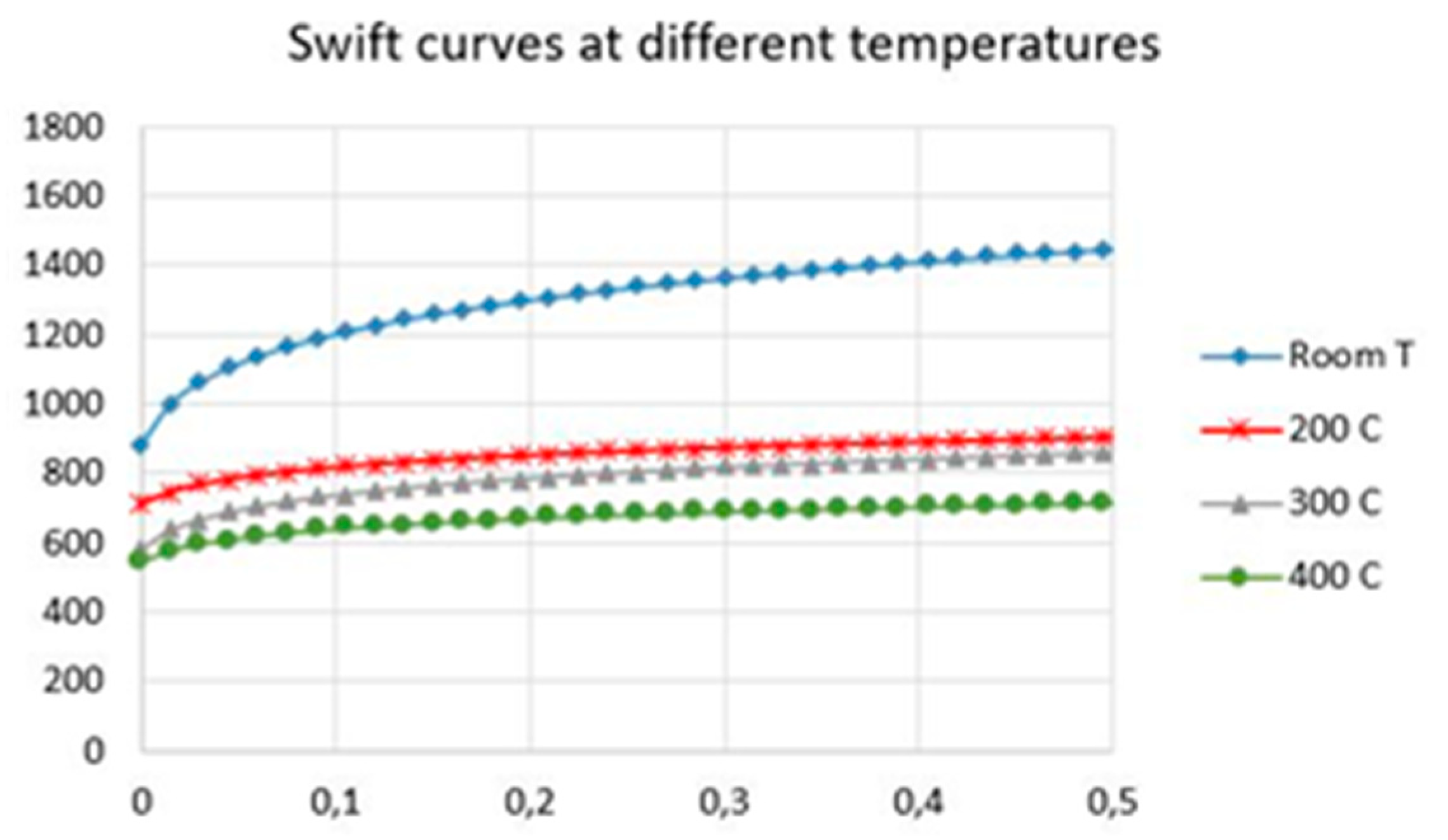
Figure 6.
Checking the plane deformation mechanism experimented during SPIF tests.

Figure 7.
(A) Experimentally measured thicknesses. (B) Equivalent deformations.

Figure 8.
Thickness obtained by FEM and experimentally. (A) Room temperature. (B) 200 °C. (C) 300 °C. (D) 400 °C.
Figure 8.
Thickness obtained by FEM and experimentally. (A) Room temperature. (B) 200 °C. (C) 300 °C. (D) 400 °C.
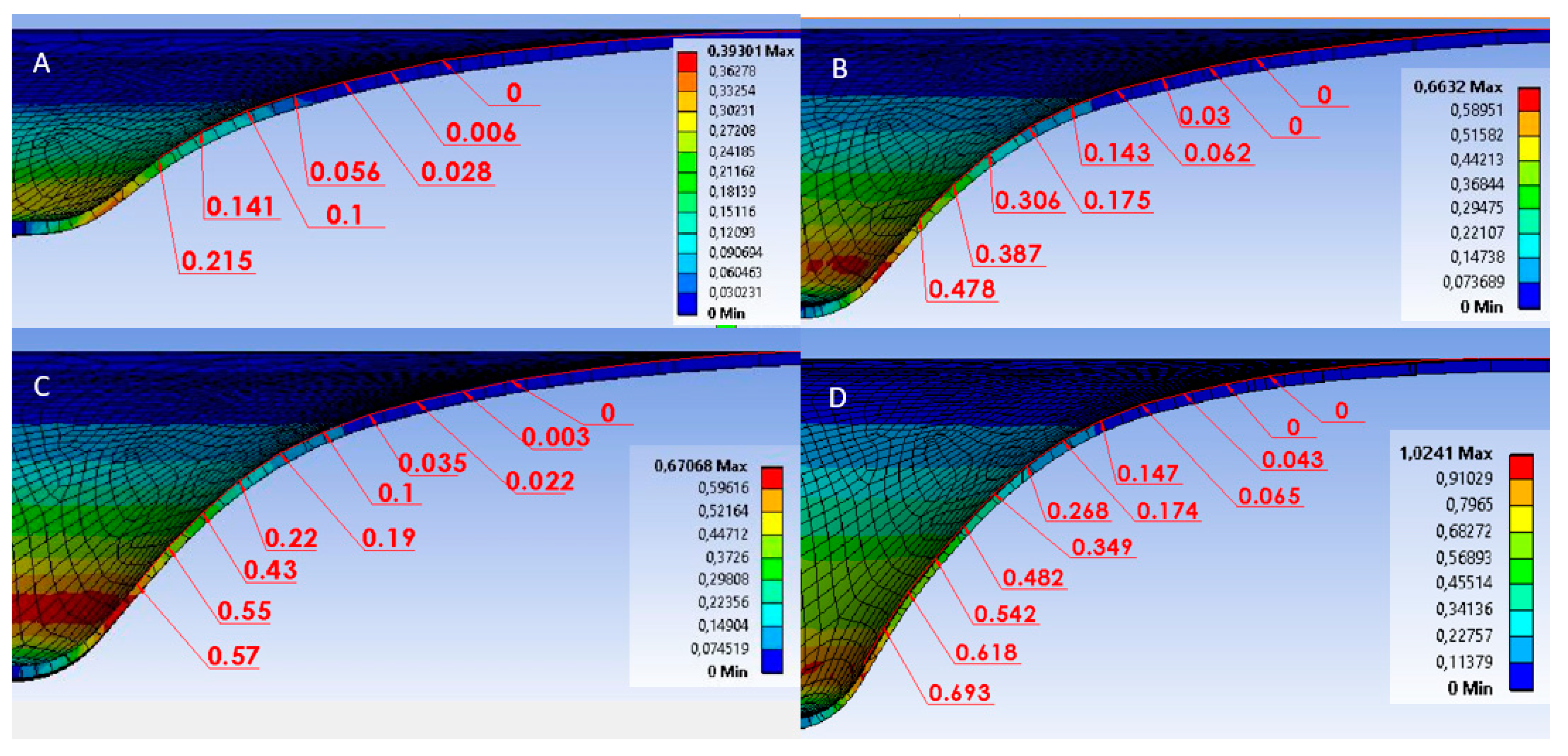
Figure 9.
(A) Tool forces on the Z-axis for different SPIF assays on constant wall angle cones. (B) Comparison of forces for truncated cones with variable and constant slopes.
Figure 9.
(A) Tool forces on the Z-axis for different SPIF assays on constant wall angle cones. (B) Comparison of forces for truncated cones with variable and constant slopes.

Figure 10.
Experimental and simulated forces on the Z-axis for assays at different temperatures.

Figure 11.
Summary of the radial forces recorded at different temperatures.

Figure 12.
Springback (A). Room temperature. (B) 200 °C. (C) 300 °C. (D) 400 °C. (E) 400 °C (constant wall angle). (F) x and ѱ springback parameters for cases (A) to (D).
Figure 12.
Springback (A). Room temperature. (B) 200 °C. (C) 300 °C. (D) 400 °C. (E) 400 °C (constant wall angle). (F) x and ѱ springback parameters for cases (A) to (D).

Figure 13.
Stress distribution obtained by FEM. (A) Room temperature. (B) 200 °C. (C) 300 °C. (D) 400 °C.
Figure 13.
Stress distribution obtained by FEM. (A) Room temperature. (B) 200 °C. (C) 300 °C. (D) 400 °C.

Figure 14.
(A) Influence of temperature on the vertical force necessary for the process. (B) Forces per unit of thickness.
Figure 14.
(A) Influence of temperature on the vertical force necessary for the process. (B) Forces per unit of thickness.

Figure 15.
Reduction of vertical force for each temperature with respect to room temperature.
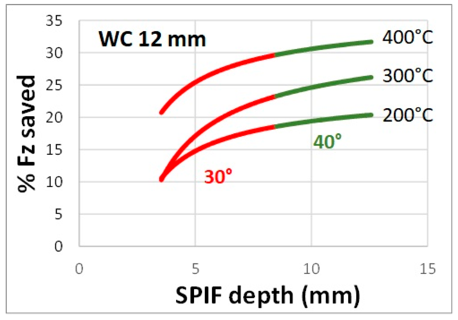
Figure 16.
Relation between radial forces and test temperature.

Figure 17.
Analytical parameters for the model of the tool-formed part contact.

Figure 18.
Forces involved in SPIF process; (A) vertical forces, Fz; (B) radial forces, Fr.

Table 1.
Mechanical properties of Ti6Al4V alloy.
| Property | Room Temp. | 150 °C | 300 °C | 450 °C |
|---|---|---|---|---|
| Modulus of elasticity (MPa) | 108,158 | |||
| UTS (MPa) | 1190 | 829 | 694 | 583 |
| Yield stress (MPa) | 970 | 774 | 580 | 522 |
| True deformation for yield stress | 0.018 | 0.0163 | 0.010 | 0.012 |
| Hardening coefficient | 0.112 | 0.051 | 0.100 | 0.055 |
| Coefficient K | 1571 | 955 | 917 | 667 |
| Mean anisotropy | 1.31 | 1.72 | 1.31 | 1.05 |
| Anisotropy at direction 0° | 0.95 | 0.93 | 0.76 | 0.65 |
| Anisotropy at direction 45° | 2 | 2.2 | 1.73 | 1.38 |
| Anisotropy direction 90° | 1.03 | 1.56 | 1.01 | 0.8 |
Table 2.
Single Point Incremental Forming tests of truncated cones with constant and variable wall angles. The angle in brackets establishes the maximum value angle with no breaking during the test in variable wall angle tests.
Table 2.
Single Point Incremental Forming tests of truncated cones with constant and variable wall angles. The angle in brackets establishes the maximum value angle with no breaking during the test in variable wall angle tests.
| Test | Temp. (°C) | Angle (°) | Max Fz (N) | Max. depth (mm) | Pitch (mm) | Tool (Diameter_(mm)/Material) | Finished | Lubricated |
|---|---|---|---|---|---|---|---|---|
| 1 | 400 | 40 | 1920 | 18 | 0.5 | 12/WC | Yes | No |
| 2 | 400 | 45 | 1900 | 18 | 0.5 | 12/WC | Yes | No |
| 3 | 400 | 50 | 1950 | 12 | 0.5 | 12/WC | No | No |
| 4 | 400 | 60 | 1950 | 9.5 | 0.5 | 12/Steel | No | No |
| 5 | 300 | 40 | 2200 | 18 | 0.5 | 12/Steel | Yes | No |
| 6 | 300 | 40 | 2300 | 18 | 0.5 | 12/Steel | Yes | No |
| 7 | 300 | 50 | 2200 | 11 | 0.5 | 12/Steel | No | No |
| 8 | 300 | 50 | 2200 | 12.5 | 0.5 | 12/Steel | No | No |
| 9 | 300 | 50 | 1850 | 9.7 | 0.25 | 12/Steel | No | No |
| 10 | 300 | 50 | 1850 | 11 | 0.25 | 12/Steel | No | No |
| 11 | 300 | 60 | 2150 | 9 | 0.5 | 12/Steel | No | No |
| 12 | Room | 30 | 2600 | 25 | 0.5 | 12/Steel | Yes | Yes |
| 13 | Room | Var (30°) | 2750 | 11.3 | 0.5 | 12/Steel | No | No |
| 14 | Room | Var (30°) | 2650 | 11.4 | 0.5 | 12/WC | No | No |
| 15 | 200 | Var (40°) | 2400 | 15.6 | 0.5 | 12/Steel | No | No |
| 16 | 200 | Var (40°) | 2300 | 17.1 | 0.5 | 12/WC | No | No |
| 17 | 300 | Var (40°) | 2500 | 17.5 | 0.5 | 12/Steel | No | No |
| 18 | 300 | Var (40°) | 2400 | 18.1 | 0.5 | 12/WC | No | No |
| 19 | 400 | Var (50°) | 2100 | 20.2 | 0.5 | 12/Steel | No | No |
| 20 | 400 | Var (50°) | 2250 | 21.1 | 0.5 | 12/WC | No | No |
| 21 | Room | Var (30°) | 2400 | 12.5 | 0.5 | 10/WC | No | No |
| 22 | 200 | Var (40°) | 2300 | 16.3 | 0.5 | 10/WC | No | No |
| 23 | 300 | Var (50°) | 2200 | 21.5 | 0.5 | 10/WC | No | No |
| 24 | 400 | Var (50°) | 1900 | 22.1 | 0.5 | 10/WC | No | No |
© 2019 by the authors. Licensee MDPI, Basel, Switzerland. This article is an open access article distributed under the terms and conditions of the Creative Commons Attribution (CC BY) license (http://creativecommons.org/licenses/by/4.0/).
Share and Cite
MDPI and ACS Style
Naranjo, J.A.; Miguel, V.; Martínez, A.; Coello, J.; Manjabacas, M.C. Evaluation of the Formability and Dimensional Accuracy Improvement of Ti6Al4V in Warm SPIF Processes. Metals 2019, 9, 272. https://doi.org/10.3390/met9030272
AMA Style
Naranjo JA, Miguel V, Martínez A, Coello J, Manjabacas MC. Evaluation of the Formability and Dimensional Accuracy Improvement of Ti6Al4V in Warm SPIF Processes. Metals. 2019; 9(3):272. https://doi.org/10.3390/met9030272
Chicago/Turabian StyleNaranjo, Jesús Andrés, Valentín Miguel, Alberto Martínez, Juana Coello, and María Carmen Manjabacas. 2019. "Evaluation of the Formability and Dimensional Accuracy Improvement of Ti6Al4V in Warm SPIF Processes" Metals 9, no. 3: 272. https://doi.org/10.3390/met9030272
Note that from the first issue of 2016, this journal uses article numbers instead of page numbers. See further details here.