Characterization and Feasibility Studies on Complete Recovery of Rare Earths from Glass Polishing Waste
by
 , , ,
, , ,
Chenna Rao Borra
1,* ,
,
Thijs J. H. Vlugt
2,
Jeroen Spooren
3,
Peter Nielsen
3,
Yongxiang Yang
1 and
S. Erik Offerman
1 1
Department of Materials Science and Engineering, Delft University of Technology, Mekelweg 2, 2628 CD Delft, The Netherlands
2
Process & Energy Department, Delft University of Technology, Leeghwaterstraat 39, 2628CB Delft, The Netherlands
3
VITO–Vlaamse Instelling voor Technologisch Onderzoek (Flemish Institute for Technological Research), Boeretang 200, B-2400 Mol, Belgium
*
Author to whom correspondence should be addressed.
Metals 2019, 9(3), 278; https://doi.org/10.3390/met9030278
Submission received: 14 January 2019
/
Revised: 20 February 2019
/
Accepted: 21 February 2019
/
Published: 28 February 2019
(This article belongs to the Special Issue Sustainable Utilization of Metals - Processing, Recovery and Recycling)
Abstract
:One of the main applications of ceria (CeO2) is its use in glass polishing. About 16,000 tonnes of rare earth oxides, which is about 10% of total rare earth production, are used for polishing applications. The waste generated in glass polishing contains rare earths, along with other impurities. In this study, two different glass polishing waste samples were characterized and two different processes were proposed for the complete recovery of rare earths from polishing waste, i.e., an acid-based process and an alkali-based process. The polishing waste samples were characterized with inductively coupled plasma optical emission spectrometry (ICP-OES), X-ray fluorescence spectroscopy (XRF), X-ray diffraction (XRD), scanning electron microscopy (SEM), thermo-gravimetric analysis (TGA) and particle size analysis. Chemical analysis showed that sample A (CeO2-rich waste from plate glass polishing) contained a high amount of impurities compared to sample B (CeO2-rich waste from mirror polishing). XRD analysis showed that sample B contained CeO2, LaO0.65F1.7 and LaPO4 compounds, whereas sample A contained CaCO3 in addition to rare earth compounds. SEM-EDX analysis showed the presence of alumino-silicates in sample A. Leaching experiments were carried out at 75 °C at different acid concentrations for the recovery of rare earths from polishing waste samples. The leaching results showed that it is difficult to dissolve rare earths completely in acid solutions due to the presence of fluorides and phosphates. Hence, undissolved rare earths in the leach residue were further recovered by an alkali treatment with NaOH. In another approach, polishing waste samples were directly treated with NaOH at 500 °C. After alkali treatment followed by water leaching, rare earths can be completely dissolved during acid leaching. Rare earths from polishing waste can be recovered completely by both the acid-based process and the alkali-based process.
1. Introduction
Cerium is the most abundant rare earth element (REE) [1]. The total estimated global reserves of cerium minerals are about 30 million tonnes [2]. The current production of ceria (CeO2) is about 54,400 tonnes, which is about 32% of rare earth oxide (REO) production [3]. Cerium is mainly used in catalysts, glass additives, polishing, ceramics, phosphors and LEDs, etc. [1]. The consumption of ceria in glass polishing is about 16,000 tonnes, which is about 10% of total RE oxide production [4].
Ceria is the primary compound in glass polishing powder as it removes the silica from the glass surface efficiently, not only by abrasion but also with chemical action [5]. The material removal rate is relatively higher and the surface is smoother when ceria based polishing powders are used compared to other commercial polishing powders. These ceria based polishing powders generally contain La together with Ce as there is a cost involved with separating La from Ce. Furthermore, La compounds do not affect the polishing quality. Ce-based polishing powders are also used for polishing silicon wafers, gems, and ceramics, etc. [4,6].
The polishing powder is used in the form of a slurry during polishing [7]. With prolonged use of the polishing powder, the particle size distribution (PSD) changes and impurities get accumulated in the powder during polishing and during the powder settling process from the slurry [6]. Hence, the powder can no longer be used in the polishing process due to the decrease in material removal rates and eventually it ends up in landfill [8]. This leads to the wastage of natural resources and causes environmental problems [9]. Therefore, the recovery of REEs is essential for the sustainable usage of glass polishing materials.
REEs can be recovered from polishing waste by physical, physico-chemical and chemical methods [10]. However, it is difficult to remove all the impurities by physical separation due to their fine particle sizes. Silica and alumina can be removed from polishing waste by alkali treatment [11,12,13,14]. However, if the waste contains other impurities or the PSD changes, it can no longer be used for polishing purposes even after alkali leaching. Therefore, acid leaching or other chemical treatments are required to recover REEs or remove impurities. Leaching of REEs from polishing waste has been reported by several authors [15,16,17,18,19,20,21,22]. However, there has been a lack of comprehensive characterisation of polishing waste and the residues or intermediate products generated during the recovery process. Furthermore, there has been no study made available on complete recovery of REEs from polishing waste and/or its acid leach residue. In this study, two different polishing waste materials generated from the glass polishing industry were characterised and the feasibility for the complete recovery of REEs from polishing waste was proposed and demonstrated using two different processes. REEs can be recovered completely from polishing waste by both acid-based and alkali-based processes.
2. Materials and Methods
Two different polishing waste samples were obtained from a mirror production industry and a plate glass producer. The sample from glass polishing was denoted sample A and the sample from mirror polishing was denoted sample B. These samples were dried at 105 °C until they reached a constant mass. Next, the material was passed through a 90 µm size mesh to remove any foreign matter before it was used for characterization and recovery studies. Analytical reagent grade HCl (37%) (Sigma-Aldrich, Zwijndrecht, The Netherlands), NaOH (Sigma-Aldrich, Zwijndrecht, The Netherlands), Na2CO3 (Sigma-Aldrich, Zwijndrecht, The Netherlands) and sodium tetraborate decahydrate (Sigma-Aldrich, Zwijndrecht, The Netherlands) were used in the present study. Chemical analysis of polishing waste was performed using two methods: (1) wavelength dispersive X-ray fluorescence spectroscopy (WDXRF, Panalytical PW2400, Almelo, The Netherlands) and (2) alkali fusion followed by acid digestion in a 1:1 (v/v) HCl solution, followed by inductively coupled plasma optical emission spectrometry (ICP-OES, Spectro Arcos-OEP, Kleve, Germany) analysis. The alkali fusion was carried out with a mixture of 0.5 g of polishing waste, 1.5 g of sodium carbonate and 1.5 g of sodium tetraborate decahydrate in a platinum crucible at 1000 °C for 60 min. The crystalline phase analysis of the samples was carried out by X-ray diffraction technique (XRD, Bruker D8 Discover, Bruker AXS GmbH, Karlsruhe, Germany). Scanning electron microscopy (SEM, Joel 6500F, Tokyo, Japan) was used for studying the powder morphology. The particle size distribution (PSD) of the samples was measured by laser particle size analysis (Microtrac S3500, Pennsylvania, USA). The leaching experiments were carried out at 75 °C for 4 h and with a liquid to solid ratio of 10:1 in a vibratory shaker (VWR Thermoshake, Zwijndrecht, The Netherlands) at 600 rpm. The acid concentration was varied from 2 to 5 M of HCl. One gram of solid sample was leached with 10 ml of HCl solution. The leach liquor was filtered using a syringe filter (pore size 0.45 µm) and diluted with distilled water for ICP-OES analysis. For alkali roasting studies, the sample was thoroughly mixed with NaOH powder by pestle and mortar. The roasting experiments were carried out at 500 °C for 4 h in a nickel crucible. After roasting, samples were leached with water at 60 °C for 1 h for the removal of sodium fluoride, sodium phosphate, and excess NaOH.
3. Results
3.1. Characterisation
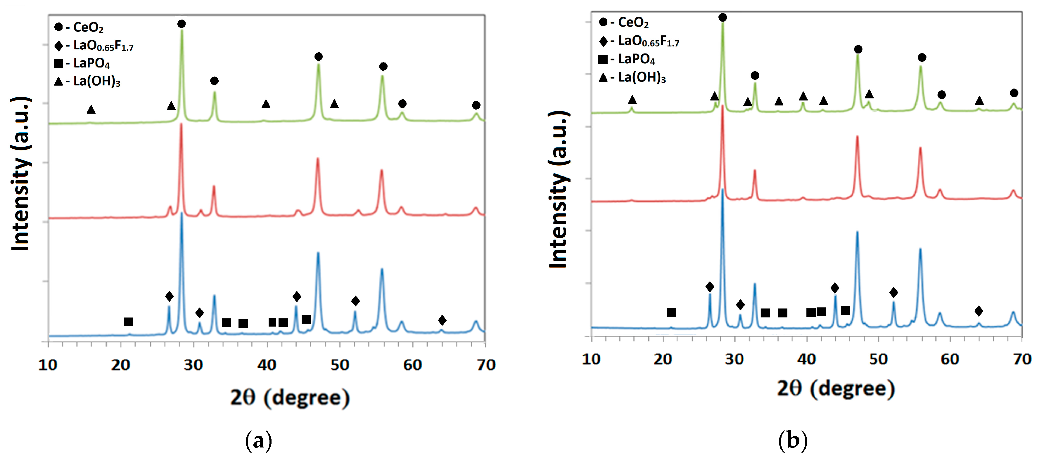
Two different samples were chosen as one sample contained only a small amount of impurities other than RE compounds and the other sample contained a very high amount of impurities. It is difficult to measure the exact composition of La and Ce in a sample using XRF due to the overlapping peaks of Ce and La. Hence, chemical analysis of ICP-OES is more accurate in finding the elemental composition of La and Ce. Chemical analysis based on XRF and ICP-OES is reported in Table 1. The table shows that sample A (from plate glass polishing) contained a high amount of impurities like Ca, Si, Al, F and P. In sharp contrast, sample B (from mirror polishing) contained mainly F and P as the main impurities. Fluoride and phosphate are used for neutralizing the basic La oxide during polishing powder manufacturing [10]. Figure 1 shows the XRD patterns of two polishing waste samples. It shows that REEs come in the form of oxides, oxyfluorides, and phosphates. Sample A contains calcite (CaCO3) together with the Ce and La compounds. However, compounds consisting of Si and Al were not observed in the XRD pattern. Nevertheless, these compounds were found in the SEM-EDX analysis of sample A and they were observed in both fine and coarse sizes. This may be due to their presence as amorphous compounds. The XRD peaks of the RE compounds showed peak shifts with respect to compounds that contained one REE (Ce or La). This is due to the presence of Ce and La together in a compound, which changes the lattice parameter (d-spacing) due to the small difference in ionic radii. For example, the CeO2 peak was shifted from 3.136 to 3.159 Å. From this peak shift, the concentration of La in CeO2 can be estimated [23]. It was found from the analysis that about 15–20% of La is present in the CeO2 phase. Similarly, La-oxyfluoride and La-phosphate phases have also shifted from their original d-spacing. La preferentially forms fluoride and phosphate over Ce as La trioxide is more basic than ceria.
Figure 2 shows the SEM micrographs of the two waste samples. RE particles are finer in sample B compared to sample A. Particle size analysis of the two samples is shown in Figure 3. The particle size analysis (Figure 2) shows that sample B is a fine material (<10 µm) compared to sample A (<100 µm). Both the samples show a multimodal particle size distribution. Impurity particles in sample A are mainly larger than 10 microns. However, these impurities were also found in the fine particle sizes together with RE particles. The high amount of submicron particles was observed in sample B and the particle size was decreased compared to the original polishing powder. As discussed earlier, the change in particle size distribution may be a reason to discard sample B, though the impurity concentration is very low in this sample. An increase in the impurity concentration is a reason to discard sample A. The particles larger than 10 µm in sample A were mainly calcite and alumino-silicates, as shown by SEM-EDX analysis. These compounds were also observed in the finer particle sizes (<10 µm).
The results of the thermogravimetric analyses of sample A and B are given in Figure 4. The high amount of weight loss in sample A is due to the presence of CaCO3, which decomposes within the temperature range 650–850 °C. Two different slopes were observed above 600 °C, which represent two different temperatures of decomposition of CaCO3. This is due to the different sizes of calcite present in the sample as observed from SEM and PSD analyses. The weight loss between 300 and 500 °C was due to organic material present in the sample. This organic material was mainly found in particle sizes above 100 µm.
3.2. Ca Removal
Ca is the major impurity in sample A. It forms insoluble oxalates during selective precipitation of RE oxalates from the leach solution and contaminates the product [24]. Hence, it needs to be removed before the leaching of REEs from the polishing waste. Although SEM analysis shows that some of the calcite particles are liberated from other particles, physical beneficiation is difficult due to the small particle size of the material. Hence, CaCO3 was removed from polishing waste by HCl leaching. Leaching was carried out with the slow addition of HCl to the slurry (Liquid to solid (L/S) ratio = 5:1) until the pH reached about 6. After leaching the residue was thoroughly washed with DI water. The dried residue after calcium removal and the leach solution were analysed. Chemical analysis of the residue showed that more than 98% of calcium was removed from the polishing waste without any removal of La and Ce from the sample. This residue was used for further studies for recovering REEs.
3.3. Alkali Leaching for Al and Si Removal
Sample A contained alumina and silica as main impurities after calcium removal. If these impurities can be removed from the waste and the material removal rate is similar to the pure polishing powder then the polishing waste can be reused. Hence, alkali leaching was carried out with 2.5 M NaOH aqueous solution and an L/S ratio of 10: 1 at 60 °C for 1 h to dissolve the Al and Si. These conditions were applied based on the literature data [11]. However, there was little to no dissolution of Si and Al in the solution. This was due to the presence of alumina and silica in compound form (confirmed from the SEM), which are difficult to dissolve in alkali solution under ambient conditions.
3.4. Acid-Based Process
High acid concentrations and high temperatures or costly reductants are required to dissolve CeO2 in nitric and sulfuric acid solutions [25]. Furthermore, sulfuric acid leaching requires additional cold-water leaching treatment to dissolve RE sulphates. HCl was chosen as it can reduce the tetravalent Ce to trivalent Ce (Reaction 1), which is easily soluble in the leach solution. Hence, hydrochloric acid was used in the current study to dissolve REEs from the polishing powder, although it does generate chlorine gas.
CeO2 + 4HCl = CeCl3 + 2H2O + ½ Cl2(g)
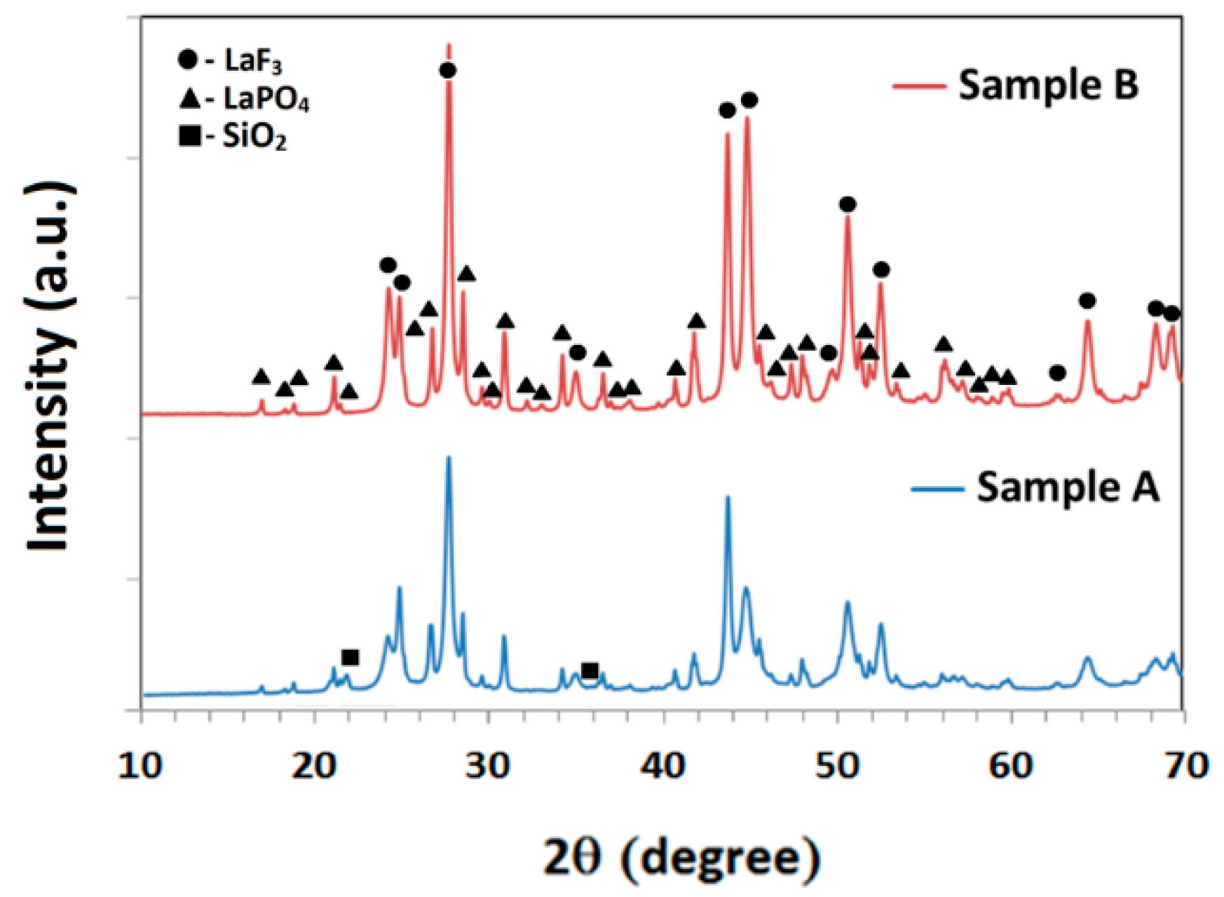
Figure 5 shows the effect of acid concentration (2–5 M) on the recovery of REEs from two different waste samples by HCl acid leaching. The temperature (75 °C) and time (4 h) were chosen for the experiments based on literature data [10] and some preliminary experiments. The recovery of Ce and La increased with the increase in HCl concentration. There was no significant increase in the recovery of Ce and La above 4 M HCl. The recovery of La and Ce were lower in sample A compared to sample B at 2 M acid concentration. This may be due to the presence of finer particles in sample B compared to sample A. However, the highest recovery for Ce was achieved at 3 M for sample A. Due to the fact that the Ce content was low in sample A compared to sample B, less acid was required for its complete dissolution. The maximum recoveries of La and Ce for both samples were between 70 to 80%. La and Ce were not completely leached due to the presence of stable compounds, i.e., fluorides and phosphates of La and Ce. As discussed earlier, polishing waste contains REEs in the form of oxides, oxyfluorides and phosphates. RE oxides readily dissolve during HCl leaching but RE fluoride and phosphates are not dissolved and report to the residue. The XRD patterns of the residues (Figure 6) show the presence of phosphate and fluoride compounds of La and Ce. Thus, according to the following reaction, oxyfluorides reacted to form RE fluorides and partially dissolve REEs.
3REOF + 6H+ = 2RE3+ + REF3 + 3H2O
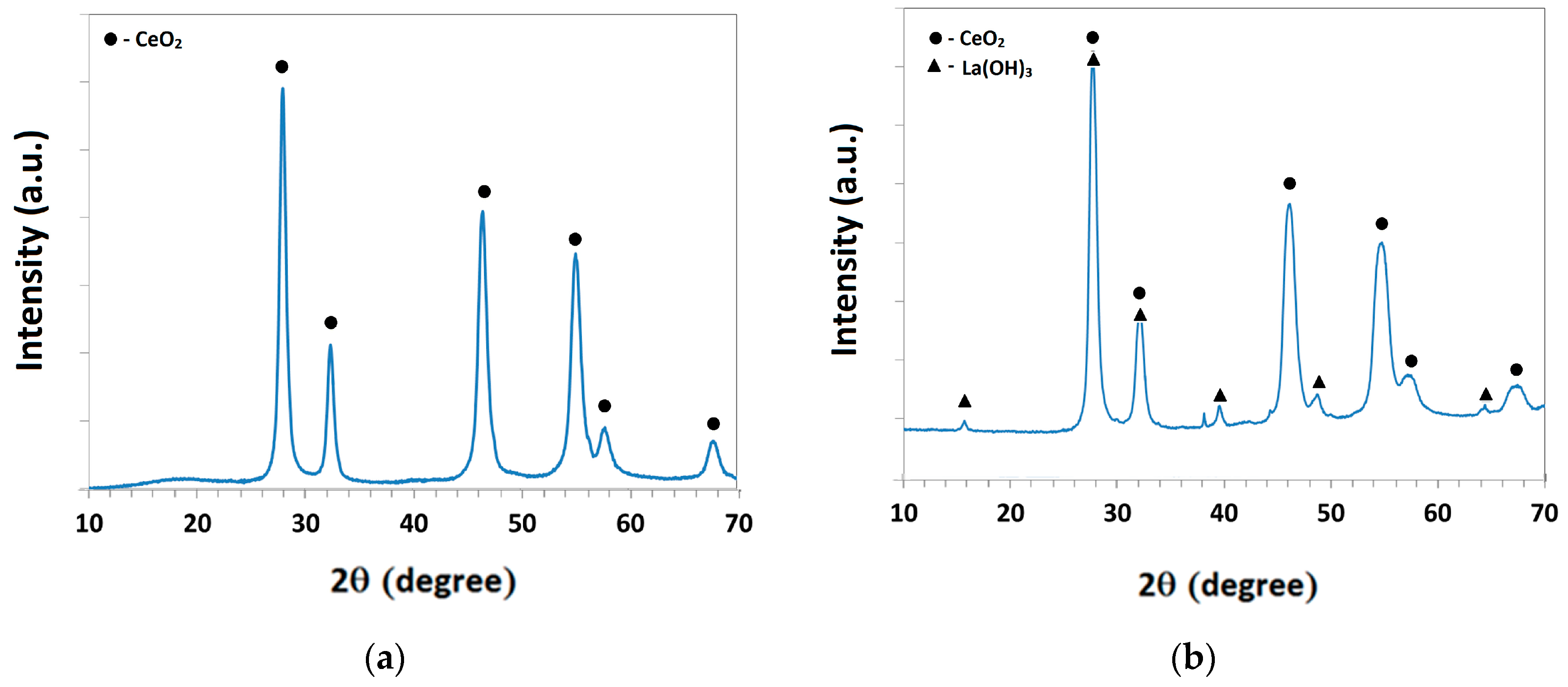
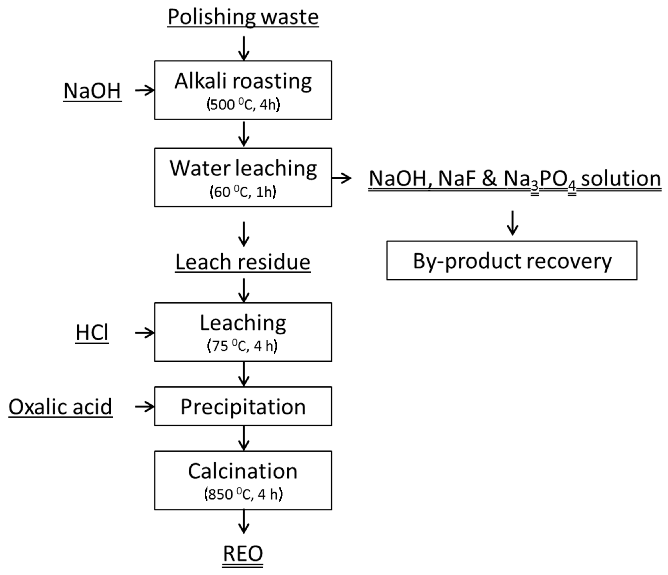
REE phosphates remained unchanged during leaching. RE phosphate and fluoride can be treated at high temperatures with sodium hydroxide to be converted to RE oxide/hydroxide. as bastnaesite (fluoride) ores are generally treated with alkali to convert stable fluorides to oxides [1]. These RE oxide/hydroxide phases are acid soluble and hence they can be selectively recovered. Hence, alkali treatment was carried out at 500 °C for 4 h with an alkali to residue ratio of 1:2. Figure 7 shows the XRD patterns of alkali treated and water leach residue samples of A and B after water leaching at 60 °C for 1 h. This figure shows that most of the fluoride and phosphate phases disappeared and converted to oxide/hydroxide phases. These samples were subsequently leached at 75 °C with 4 M HCl and an L/S ratio of 5 for 1 h, and more than 95% of the REEs were dissolved into the leach solution. REEs can be selectively recovered from the leach solution by oxalic acid precipitation. The precipitated RE oxalates can be converted to RE oxides by calcination. If the product purity is not sufficient then the REEs can be selectively separated by solvent extraction before the oxalic acid precipitation [1]. The acid regenerated after oxalic acid precipitation can be reused in leaching after adding make up acid. The flowsheet for complete recovery of REEs from polishing waste by acid leaching followed by alkali treatment is shown in Figure 8.
3.5. Alkali-Based Process
As explained earlier, it is difficult to completely recover REEs from polishing waste only by acid leaching. Therefore, in an alternative approach, alkali treatment of the polishing waste was carried out to convert acid insoluble compounds to acid-soluble compounds. Figure 9 shows the flowsheet for an alkali-based process for complete recovery of REEs from glass polishing waste. Alkali treatment of polishing waste converts oxyfluorides and phosphates to oxide/hydroxides of REEs according to the following reactions:
REOF + NaOH = NaF + RE2O3/REO2/RE(OH)3 + H2O
REPO4 + NaOH = Na3PO4 + RE2O3/REO2/RE(OH)3 + H2O
The waste samples were roasted with two different ratios of NaOH at 500 °C for 4 h. After alkali treatment, the roasted samples were washed with water at 60 °C for 1 h to dissolve NaF, Na3PO4 and other water-soluble compounds. NaOH, NaF and Na3PO4 can be recovered from the solution by evaporation/crystallization [1]. The recovered NaOH can be reused in the roasting process. Figure 10 shows the XRD analysis of two samples after alkali treatment followed by water washing. Fluoride was not completely removed from the samples at a NaOH to sample ratio of 0.3. Most of the F and P was removed from the samples at a NaOH to sample ratio of 0.6. The sample after alkali treatment and water washing was dissolved in 6 M acid solution for the recovery of REEs at 75 °C for 4 h. The recovery of La and Ce exceeded 95%. After filtration, the pH of the solution was raised to 5 to remove impurities. Next, the REEs were precipitated from the solution with oxalic acid at a ratio of REEs to oxalic acid of 1:2.
The recovered REO could be used again as a polishing agent or in other direct applications, or, alternatively, the REO could be reduced to metallic Ce or Misch metal and form a new alloy with other metals such as Al through molten slat electrolysis. The further processing of REO for alloy preparation is under way and will be published in the near future.
4. Conclusions
In this study, two different polishing waste materials (A and B) were analysed using XRF, XRD, SEM, ICP-OES, PSD and TGA analyses. Sample A (plate glass polishing) contained large amounts of impurities like Ca, Al, Si, F and P, whereas sample B (mirror polishing) contained mainly F and P. Sample B was a finer material compared to sample A. REEs were found in the form of CeO2, LaO0.65F1.7 and LaPO4. Direct acid leaching of the samples with HCl at 75 °C for 4 h with a L/S ratio of 10 dissolved only a maximum of 80% of the REEs. However, an additional alkali treatment at 500 °C for 4 h was able to convert undissolved RE fluoride and phosphates to hydroxides or oxides. These hydroxides or oxides were further purified by acid leaching followed by selective precipitation or solvent extraction, followed by REE precipitation. REEs were also to be recovered by direct alkali treatment of polishing waste at 500 °C for 4 h followed by water leaching at 60 °C for 1 h and subsequent acid leaching at 75 °C for 4 h, which yielded a REE leachability of >95%. This study shows that REEs can be completely recovered from polishing waste via both acid-based and alkali-based processes. However, a detailed study is required to optimise the process conditions and to study the process economics.
Author Contributions
Funding acquisition, T.J.H.V., Y.Y. and S.E.O.; investigation, C.R.B.; methodology, C.R.B., T.J.H.V., Y.Y. and S.E.O.; resources, T.J.H.V., J.S., P.N., Y.Y. and S.E.O.; supervision, T.J.H.V., Y.Y. and S.E.O.; writing—original draft, C.R.B.; writing—review & editing, C.R.B., T.J.H.V., J.S., P.N., Y.Y. and S.E.O.
Acknowledgments
T.J.H.V. acknowledges Nederlandse Organisatie voor Wetenschappelijk Onderzoek-Chemische Wetenschappen (NWO-CW) for a VICI grant. C.R.B. acknowledges TU Delft for funding the 3mE Cohesion project: “Sustainable Rare-earth Cycle”. The authors acknowledge Michel van den Brink of TU Delft for ICP-OES and PSD analyses and Ruud Hendrikx of TU Delft for XRD and XRF analyses.
Conflicts of Interest
The authors declare no conflict of interest.
References
- Krishnamurthy, N.; Gupta, C.K. Extractive Metallurgy of Rare Earths; CRC Press: Boca Raton, FL, USA, 2015; ISBN 1466576383. [Google Scholar]
- Argus Media Analysing the Changing Global Rare Earths Supply and Demand Outlook. Available online: http://www.argusmedia.jp/~/media/files/pdfs/regional-specific/jp/downloads/argus-metal-pages-forum082016-rareearths.pdf/?la=en (accessed on 16 February 2017).
- Gambogi, J. USGS 2014 Minerals Yearbook: Rare Earths; USGS: Reston, VA, USA, 2016.
- Tercero Espinoza, L.; Hummen, T.; Brunot, A.; Hovestad, A.; Peña Garay, I.; Velte, D.; Smuk, L.; Todorovic, J.; Van Der Eijk, C.; Joce, C. Critical Raw Materials Substitution Profiles; Fraunhofer Institute for Systems and Innovation Research: Karlsruhe, Germany, 2015. [Google Scholar]
- Lucas, J.; Lucas, P.; Le Mercier, T.; Rollat, A.; Davenport, W. Chapter 12—Polishing with Rare Earth Oxides Mainly Cerium Oxide CeO2. In Rare Earths; Elsevier: Amsterdam, The Netherlands, 2015; pp. 191–212. ISBN 978-0-444-62735-3. [Google Scholar]
- Binnemans, K.; Jones, P.T.; Blanpain, B.; Van Gerven, T.; Yang, Y.; Walton, A.; Buchert, M. Recycling of rare earths: A critical review. J. Clean. Prod. 2013, 51, 1–22. [Google Scholar] [CrossRef]
- Kasai, T.; Bhushan, B. Physics and tribology of chemical mechanical planarization. J. Phys. Condens. Matter 2008, 20, 225011–225023. [Google Scholar] [CrossRef]
- Um, N.; Hirato, T. A hydrometallurgical method of energy saving type for separation of rare earth elements from rare earth polishing powder wastes with middle fraction of ceria. J. Rare Earths 2016, 34, 536–542. [Google Scholar] [CrossRef]
- Mishima, F.; Terada, T.; Akiyama, Y.; Nishijima, S. High Gradient Superconducting Magnetic Separation for Iron Removal from the Glass Polishing Waste. IEEE Trans. Appl. Supercond. 2011, 21, 2059–2062. [Google Scholar] [CrossRef]
- Borra, C.R.; Vlugt, T.J.H.; Yang, Y.; Offerman, S.E. Recovery of Cerium from Glass Polishing Waste: A Critical Review. Metals 2018, 8, 801. [Google Scholar] [CrossRef]
- Kato, K.; Yoshioka, T.; Okuwaki, A. Study for recycling of ceria-based glass polishing powder. Ind. Eng. Chem. Res. 2000, 39, 943–947. [Google Scholar] [CrossRef]
- Kato, K.; Yoshioka, T.; Okuwaki, A. Recyle of Ceria-Based Glass Polishing Powder Using NaOH Solution. Nippon Kagaku Kaishi 2000, 10, 725–732. [Google Scholar] [CrossRef]
- Moon, W.; Na, S.; Oh, H. Method for Recycling Cerium Oxide Abrasive. U.S. Patent 20110219704A1, 15 September 2011. [Google Scholar]
- Matsui, H.; Harada, D.; Takeuchi, M. Method for Recovery of Cerium Oxide. U.S. Patent 20130152483A1, 20 June 2013. [Google Scholar]
- Janoš, P.; Kuráň, P.; Ederer, J.; Šastný, M.; Vrtoch, L.; Pšenička, M.; Henych, J.; Mazanec, K.; Skoumal, M. Recovery of Cerium Dioxide from Spent Glass-Polishing Slurry and Its Utilization as a Reactive Sorbent for Fast Degradation of Toxic Organophosphates. Adv. Mater. Sci. Eng. 2015, 8. [Google Scholar] [CrossRef]
- Poscher, A.; Luidold, S.; Schnideritsch, H.; Antrekowitsch, H. Extraction of Lanthanides from Spent Polishing Agent. In Rare Earths Industry: Technological, Economic, and Environmental Implications; Elsevier Inc.: Amsterdam, The Netherlands, 2015; pp. 209–222. ISBN 9780128023280. [Google Scholar]
- Poscher, A.; Luidold, S.; Antrekowitsch, H. Extraction of cerium and lanthanum from spent glass polishing agent. In Materials Science & Technology 2013; London, I.M., Goode, J.R., Moldoveanu, G., Rayat, M.S., Eds.; Canadian Institute of Mining, Metallurgy and Petroleum: Montréal, QC, Canada, 2013; pp. 543–552. [Google Scholar]
- Henry, P.; Lamotte, S.; Bier, J. Recycling of rare earth materials at Hydrometal (Belgium). In 52nd Conference of Metallurgists (COM), Hosting by Materials Science Technology Conference (MS&T); London, I.M., Goode, J.R., Moldoveanu, G., Rayat, M.S., Eds.; Canadian Institute of Mining, Metallurgy and Petroleum: Montréal, QC, Canada, 2013; pp. 537–542. [Google Scholar]
- Byeon, M.S.; Kim, J.Y.; Hwang, K.T.; Kim, U.; Cho, W.S.; Kang, W.K. Recovery and purification of cerium from glass polishing slurry. In Proceedings of the 18th International Conference on Composite Materials, Jeju, Korea, 21–26 August 2011. [Google Scholar]
- Kim, J.Y.; Kim, U.S.; Byeon, M.S.; Kang, W.K.; Hwang, K.T.; Cho, W.S. Recovery of cerium from glass polishing slurry. J. Rare Earths 2011, 29, 1075–1078. [Google Scholar] [CrossRef]
- Janoš, P.; Novak, J.; Broul, M. A Procedure for Obtaining Salts of Rare Earth Elements. U.S. Patent 21,039,151, 31 October 1988. [Google Scholar]
- Terziev, A.L.; Minkova, N.L.; Todorovsky, D.S. Regeneration of waste rare earth oxides based polishing materials. Bulg. Chem. Commun. 1996, 29, 274–284. [Google Scholar]
- Ryan, K.M.; McGrath, J.P.; Farrell, R.A.; O Neill, W.M.; Barnes, C.J.; Morris, M.A. Measurements of the lattice constant of ceria when doped with lanthana and praseodymia—The possibility of local defect ordering and the observation of extensive phase separation. J. Phys. Condens. Matter 2003, 15, L49–L58. [Google Scholar] [CrossRef]
- Chi, R.; Zhang, X.; Zhu, G.; Zhou, Z.A.; Wu, Y.; Wang, C.; Yu, F. Recovery of rare earth from bastnasite by ammonium chloride roasting with fluorine deactivation. Miner. Eng. 2004, 17, 1037–1043. [Google Scholar] [CrossRef]
- Um, N.; Hirato, T. Dissolution Behavior of La2O3, Pr2O3, Nd2O3, CaO and Al2O3 in Sulfuric Acid Solutions and Study of Cerium Recovery from Rare Earth Polishing Powder Waste via Two-Stage Sulfuric. Acid Leach. Mater. Trans. 2013, 54, 713–719. [Google Scholar] [CrossRef]
Figure 1.
X-ray diffraction (XRD) patterns of polishing waste samples. Sample A is from plate glass polishing and sample B is from mirror polishing.
Figure 1.
X-ray diffraction (XRD) patterns of polishing waste samples. Sample A is from plate glass polishing and sample B is from mirror polishing.

Figure 2.
Scanning electron microscopy (SEM) images of the polishing waste samples: (a) sample A shows the coarser particles and (b) sample B shows the finer particles. Sample A is from plate glass polishing and sample B is from mirror polishing.
Figure 2.
Scanning electron microscopy (SEM) images of the polishing waste samples: (a) sample A shows the coarser particles and (b) sample B shows the finer particles. Sample A is from plate glass polishing and sample B is from mirror polishing.

Figure 3.
Particle size distribution of polishing waste samples. Sample B shows finer particles, whereas sample A shows coarser particles. Sample A is from plate glass polishing and sample B is from mirror polishing.
Figure 3.
Particle size distribution of polishing waste samples. Sample B shows finer particles, whereas sample A shows coarser particles. Sample A is from plate glass polishing and sample B is from mirror polishing.

Figure 4.
Thermo-gravimetric analysis (TGA) analysis of the two polishing waste samples shows high amount of weight loss in sample A compared to sample B upon heating. Sample A is from plate glass polishing and sample B is from mirror polishing.
Figure 4.
Thermo-gravimetric analysis (TGA) analysis of the two polishing waste samples shows high amount of weight loss in sample A compared to sample B upon heating. Sample A is from plate glass polishing and sample B is from mirror polishing.

Figure 5.
Effect of HCl concentration on leaching of rare earth elements (REEs) from polishing waste samples (T: 75 °C, t: 4 h, L/S: 10). The recovery of La and Ce was lower in (a) sample A compared to (b) sample B at low acid concentrations. However, the maximum recoveries of La and Ce were similar for both samples at high acid concentrations, which were about 70%. Sample A is from plate glass polishing and sample B is from mirror polishing.
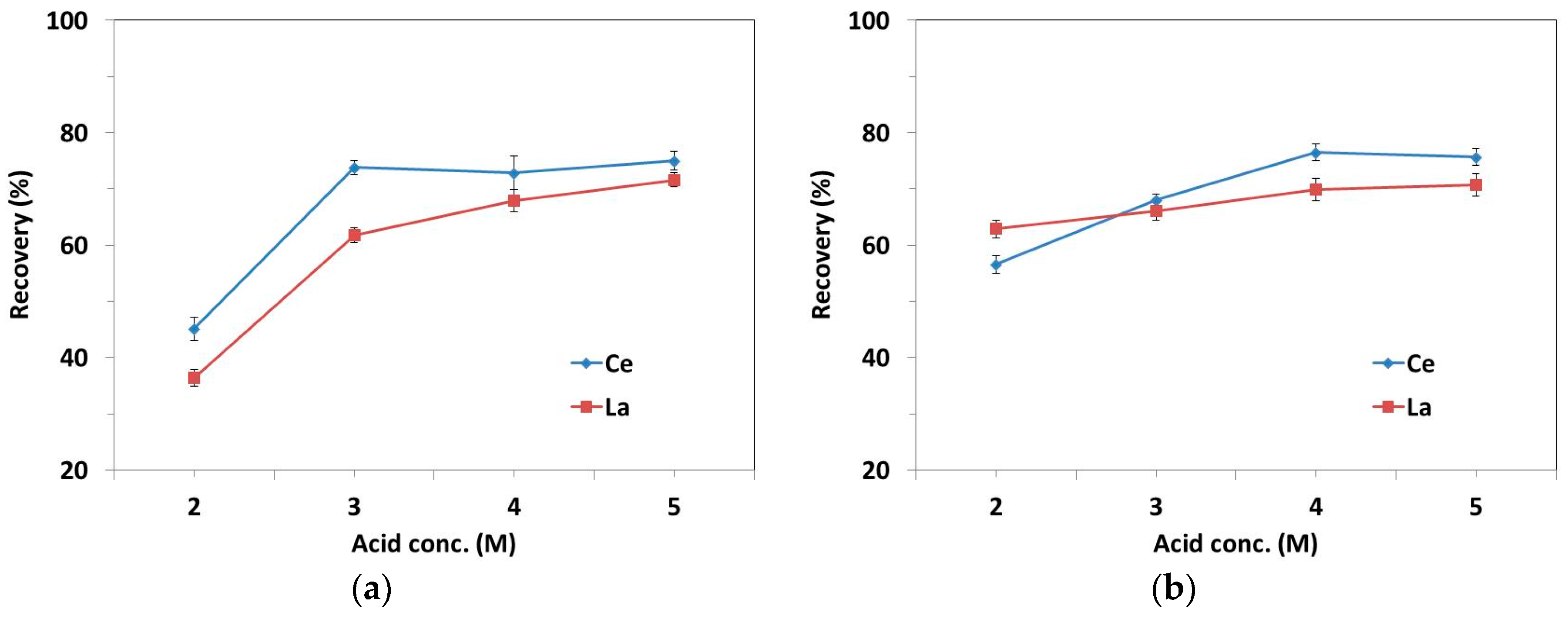
Figure 6.
XRD patterns of acid leach residue show mainly the peaks of rare earth (RE) fluorides and phosphates. Sample A is from plate glass polishing and sample B is from mirror polishing.
Figure 6.
XRD patterns of acid leach residue show mainly the peaks of rare earth (RE) fluorides and phosphates. Sample A is from plate glass polishing and sample B is from mirror polishing.

Figure 7.
XRD patterns of acid leach residue samples after alkali treatment and water leaching. (a) Sample A is from plate glass polishing and (b) sample B is from mirror polishing.
Figure 7.
XRD patterns of acid leach residue samples after alkali treatment and water leaching. (a) Sample A is from plate glass polishing and (b) sample B is from mirror polishing.

Figure 8.
Flowsheet for complete recovery of REEs from polishing waste by acid-based process. This flowsheet shows that polishing waste was treated by acid leaching followed by alkali treatment.
Figure 8.
Flowsheet for complete recovery of REEs from polishing waste by acid-based process. This flowsheet shows that polishing waste was treated by acid leaching followed by alkali treatment.

Figure 9.
Flowsheet for complete recovery of REEs from polishing waste via an alkali-based process. This flowsheet shows that polishing waste was treated by alkali roasting, followed by acid leaching.
Figure 9.
Flowsheet for complete recovery of REEs from polishing waste via an alkali-based process. This flowsheet shows that polishing waste was treated by alkali roasting, followed by acid leaching.

Figure 10.
XRD patterns of alkali treated and water leached samples at different alkali to polishing waste samples (blue line: original sample; red line: alkali to sample ratio—0.3; green line: alkali to sample ratio—0.6). Sample A (a) is from plate glass polishing and sample B (b) is from mirror polishing.


Table 1.
Chemical analysis of polishing waste samples. Sample A (from plate glass polishing) contains a high amount of impurities whereas sample B (from mirror polishing) contains a small amount of impurities. Legend: ICP-OES, inductively coupled plasma optical emission spectrometry; WD-XRF: wavelength dispersive X-ray fluorescence spectroscopy.
| Elements | Sample A (wt.%) | Sample B (wt.%) | Analysis |
|---|---|---|---|
| Ce | 23.3 ± 0.7 | 52.2 ± 1.5 | ICP-OES |
| La | 9.1 ± 0.3 | 18.7 ± 0.6 | |
| F | 2.3 | 5.9 | WD-XRF |
| Si | 2.6 | 0.4 | |
| Al | 2.2 | - | |
| Ca | 20.8 | 0.2 | |
| Fe | 0.4 | 0. 6 | |
| P | 0.4 | 0.9 | |
| Ba | 0.2 | 0.4 | |
| Na | 0.2 | - | |
| Mg | 0.1 | - | |
| Ti | 0.1 | - | |
| Sn | 0.1 | 0.4 | |
| Ag | - | 0.2 |
© 2019 by the authors. Licensee MDPI, Basel, Switzerland. This article is an open access article distributed under the terms and conditions of the Creative Commons Attribution (CC BY) license (http://creativecommons.org/licenses/by/4.0/).
Share and Cite
MDPI and ACS Style
Borra, C.R.; Vlugt, T.J.H.; Spooren, J.; Nielsen, P.; Yang, Y.; Offerman, S.E. Characterization and Feasibility Studies on Complete Recovery of Rare Earths from Glass Polishing Waste. Metals 2019, 9, 278. https://doi.org/10.3390/met9030278
AMA Style
Borra CR, Vlugt TJH, Spooren J, Nielsen P, Yang Y, Offerman SE. Characterization and Feasibility Studies on Complete Recovery of Rare Earths from Glass Polishing Waste. Metals. 2019; 9(3):278. https://doi.org/10.3390/met9030278
Chicago/Turabian StyleBorra, Chenna Rao, Thijs J. H. Vlugt, Jeroen Spooren, Peter Nielsen, Yongxiang Yang, and S. Erik Offerman. 2019. "Characterization and Feasibility Studies on Complete Recovery of Rare Earths from Glass Polishing Waste" Metals 9, no. 3: 278. https://doi.org/10.3390/met9030278
Note that from the first issue of 2016, this journal uses article numbers instead of page numbers. See further details here.