Performance of Plunge Depth Control Methods During Friction Stir Welding


1
Joining Research Group, Korea Institute of Industrial Technology, Incheon 21999, Korea
2
School of Mechanical Engineering, Hanyang University, Seoul 04763, Korea
3
Department of Mechanical and Materials Engineering, Portland State University, Portland, OR 97201, USA
*
Author to whom correspondence should be addressed.
Metals 2019, 9(3), 283; https://doi.org/10.3390/met9030283
Submission received: 13 February 2019
/
Revised: 26 February 2019
/
Accepted: 27 February 2019
/
Published: 2 March 2019
(This article belongs to the Special Issue Friction Stir Welding and Processing in Alloy Manufacturing)
Abstract
:Friction stir welding is a preferred solid state welding process for Al/Fe joints, and in friction stir lap welding, the plunge depth is the most critical parameter for joint strength. We compared three plunge depth control methods, namely conventional position control, offset position control, and deflection compensation control in the friction stir lap welding of 3 mm-thick Al 5083-O alloy over 1.2 mm-thick DP 590 steel. The desired plunge depth was 0.2 mm into the steel sheet. However, the pin did not reach the steel surface under conventional position control due to deflection of the vertical axis of the welding system. In offset position control, an additional offset of 0.35 mm could achieve the desired plunge depth with considerable accuracy. Nevertheless, a gradual increase of the plunge depth along the longitudinal direction was unavoidable, due to an in-situ decrease of the material yield strengths. In deflection compensation control, the deflection is estimated by the coaxially measured plunging force and the force-deflection relationship, and then corrected by feedback control. Thus, the plunge depth is stabilized along the longitudinal direction and is precisely controlled with a 3.3-μm standard deviation of error during the tool traverse phase. There is also a consistent bias of 32 μm caused by the resolution of the measuring system, and it can be easily calibrated in the feedback control system.
1. Introduction
In the automotive industry, there is rapidly increasing use of high-strength steels and aluminum to reduce the weight of vehicles. To improve the performance and price competitiveness of automobiles, the development of a multi-materials car body, which adopts various materials simultaneously into the parts, is an important issue. Thus, there is growing research interest in the joining technology of different materials [1,2]. Steel together with Al alloy is considered the most important dissimilar material combination, for which various approaches have been investigated [3]. During the fusion welding of steel and Al alloy, a low heat input process is preferred because the joining strength is reduced by the formation of an intermetallic compound (IMC). Galvanic corrosion is another critical issue for the Al/Fe combination as it hinders the durability of the joint [4,5,6]. Currently, the preferred industrial methods are adhesive bonding and mechanical joining techniques, such as riveting and clinching, because of no IMC formation and high galvanic corrosion [3,7]. However, there is a continuous demand for more economical welding techniques. Solid state welding can drastically reduce IMC formation and ensure high bonding strength compared to fusion welding. The Honda Motor Company successfully applied friction stir welding (FSW) for dissimilar metals of Al/Fe in the commercial mass production of Accord 2013 model cars [8]. They applied robotic FSW on Al/Fe overlap joints to weld the latter by forming a thin IMC layer of Fe4Al13. In this case, the pin on the FSW tool plunged through the upper Al part and slightly penetrated the top of the lower steel part.
Various FSW techniques for Al/Fe joints and the resultant joint properties were extensively reviewed by Hussein et al. [9]. Those authors classified the techniques into three types: Diffusion, plunging, and annealing; and described the characteristics of various processes. The entire FSW sequence can also be divided into three phases in time: The plunge and dwell, tool traverse, and retract phases [10]. In terms of the joining strength, the position of the pin during the plunge and traverse phases, called the plunge depth, is the most important parameter. Kimapong et al. first implemented FSW on Al/Fe butt joints, and the highest joining strength (about 86% of that of the Al base material) was achieved when the pin was mostly on the Al side with 0.2 mm inserted into the steel side [11]. In the friction stir lap welding (FSLW) of Al/Fe joints, Al is usually placed on top of the steel, and the pin penetrates the lower steel plate by 0.1 to 0.2 mm [12,13,14]. The change of the plunge depth influences the joining strength by either changing the shape of the “hook” formed at the interface [15] or inducing excessive IMC growth by heat generation [16]. Excessive plunge depths can also cause tool wear and reduce the tool life. Therefore, it is very important to maintain a small penetration depth into the lower steel sheet in the FSLW of the Al/Fe overlap joint.
The FSW system can be implemented by conventional machine tools, dedicated FSW machines, or industrial robots [17]. In all these systems, the tool position is basically controlled by pure position control. In the FSLW of the Al/Fe joint, when the pin tip penetrates the steel, there is a higher axial load and subsequent deflection of the system. This system deflection is not compensated for by the position control, and so both the plunge depth and joining strength are reduced. Smith [18] and Cook et al. [19] reported that deflection in the FSLW system could be reduced and the welding quality enhanced by the constant plunging force control. In their subsequent research, Cook and coworkers [20] evaluated the plunge depth, traverse speed, and rotation speed as control parameters to maintain a constant plunging force. Although the plunging force control can considerably compensate for system deflection compared to conventional position control, it has two drawbacks. First, because the plunging force is affected by not only the plunge depth, but also other process parameters (such as the traverse speed and rotation speed), the plunging force required to reach a certain plunge depth varies with the process parameters [17,19,20]. Second, even if a constant plunging force can be maintained, the actual plunge depth may be inappropriate when the yield strength of the base materials changes with temperature. Thus, Smith and coworkers [21] implemented simultaneous temperature control with the plunging force control in order to improve the joint quality.
The offset position control is carried out by adding a certain offset to the reference position. Being simpler than the constant plunging force control, it is often applied to compensate for the system deflection. However, characteristics of this control process have not been reported so far. Very recently, our group reported a force-deflection model to compensate for the position error in friction stir spot welding (hereafter called the deflection compensation control) [22]. The axial load, i.e., the plunging force was coaxially measured using a load cell, and the deflection estimated by the force-deflection model was compensated for. Importantly, the relationship between the axial load and the system deflection depends only on the stiffness of the welding system rather than the base materials or process parameters. By using the proposed model, the plunge depth could be controlled with an error of less than 50 µm for various process parameter sets. In this paper, we further compare the deflection compensation control to the conventional position control and the offset position control methods in terms of effectively controlling the plunge depth and joint properties.
2. Experimental Setup
The base materials were Al 5083-O alloy with a thickness of 3.0 mm and dual phase (DP) 590 steel with a thickness of 1.2 mm. Their chemical compositions are given in Table 1. The welding tool was made of tungsten carbide with 12% Co; and the pin length, pin diameter, and shoulder diameter were 2.7, 3.0, and 12 mm, respectively. Details of the tool shape were given in the previous paper [22]. As shown in Figure 1, the Al alloy sheet is overlaid on the steel sheet for the FSLW, and the welding tool is tilted by 3° against the welding direction. The desired plunge depth is set at 3.2 mm, where the pin of the welding tool penetrates the bottom sheet by 0.2 mm. An insufficient plunging leads to a reduced interface area, and excessive plunging causes excess IMC formation [14,16,23,24].
The conventional position control and offset position control were implemented by a computer numerical control (CNC) machine controller in the 3-axis cartesian FSW system. The deflection compensation control was implemented using co-axial load measurement and feedback control (Figure 2). In the feedback control, the axial deflection of the FSW system is estimated and compensated for by using a linear load-deflection relationship. Details of the measurement system, control system, and the control algorithm can be found in the previous paper [22].
In the position control and the deflection compensation control, the tool rotation speed and welding speed are selected as process parameters while the plunging speed and dwell time are fixed at 20 mm/min and 7 s, respectively. The tool rotation speed has 3 levels (500, 700, and 900 rpm) and the welding speed also has 3 levels (100, 150, and 200 mm/min) in the experiments. The actual plunge depth was recorded by a linear variable differential transformer (LVDT) sensor, and the force and torque were recorded by a coaxial sensor. For the offset position control, the tool rotation speed and welding speed were fixed at 700 rpm and 150 mm/min, respectively, while only the offset value to compensate for the axial deflection was varied from 0.20 to 0.55 mm.
Five tensile shear specimens were prepared for each condition according to ISO 6892, with a gage length of 60 mm, a gage width of 12.5 mm, and an overlap length of 50 mm. The load upon fracture was measured under a test speed of 5 mm/min.
3. Results and Discussion
3.1. Conventional Position Control
When using the conventional position control, none of the nine parameters sets could allow the pin to penetrate the lower steel sheet at all, while a penetration depth of 0.2 mm is desired (Figure 3). This insufficient penetration is caused by deflection of the system, which is intrinsically not compensated for in this case.
Nevertheless, the plunge depth slightly decreases with the advance per revolution (APR), which is defined by the ratio of the welding speed to the tool rotation speed (Figure 4) [10]. The concept of APR is similar to the reciprocal of the heat input per unit length in convention fusion welding. The lower the APR, the higher the temperature and the lower the yield strength of the base materials. In these experiments, the plunge depth varies within only a small range of 55 µm, because the entire welding pin remains within the upper Al sheet.
3.2. Offset Position Control
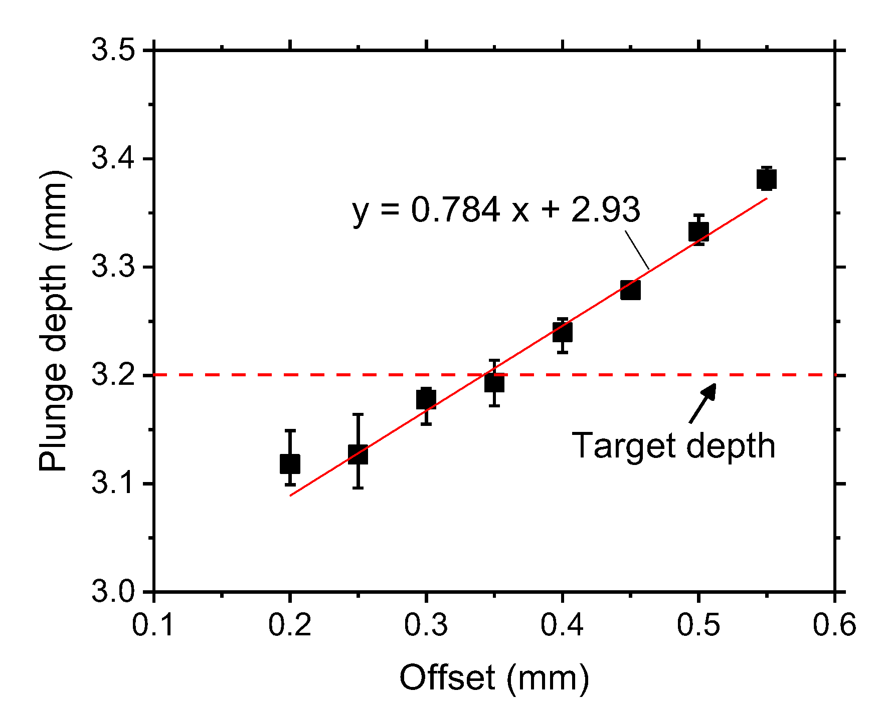
When an additional offset of 0.20–0.55 mm is assigned in the position control to compensate for the vertical deflection of the system, the measured plunge depth linearly increases from 3.11 to 3.38 mm (Figure 5), while the desired plunge depth is 3.2 mm. The slope and intercept of the linear fitting line are 0.784 and 2.93 mm, respectively. Note that the slope is not in unity and can vary with the process parameters. For this reason, the adequate offset for a given plunge depth is hard to estimate, and it used to be determined by experimental trial and error.
When the plunge depth is set to 3.55 mm in the position control system, i.e., an offset of 0.35 mm, the actual plunge depth is nearest to the desired value of 3.2 mm (Figure 5). However, even for this case, the measured plunge depth fluctuates with time, and the variation range is 42 µm (Figure 6) during the tool traverse phase. At the same time, the axial force continuously decreases from 7.4 to 6.1 kN assuming the linear fit. Because the temperature of the specimen increases with time, a lower force and a higher plunge depth were observed. The deflection can be calculated from the measured force by using the force-deflection model developed in the previous study [22]. When calculated with the given change of the axial force, the difference in the system deflections before and after the tool traverse phase is estimated as 45 µm, which agrees very well with the measured difference in the plunge depth (42 µm).
Tensile shear test was conducted for specimens taken at every 20 mm along the weld bead (Figure 7). The maximum fracture load is 4.2 kN, and the range of the load is 0.9 kN. The gradual decrease of the fracture load can originate from the increasing plunge depth and temperature, which promote growth of IMC during the joining of Al/Fe metals [16,25]. The difference in the fracture load at different positions is more than 20%, which can cause an overdesign of welds and a decease in the productivity and quality of the process.
3.3. Deflection Compensation Control
When the deflection compensation control is applied, both the plunge depth and axial force are stabilized during the entire tool traverse phase (Figure 8). The average value and range of the plunge depth are 3.23 mm and 14 µm, respectively, while the desired depth is 3.2 mm. A bias of around 30 µm was observed and attributed to the resolution of the load measuring system, similar to the previous study [22]. The plunge depth is well controlled under various welding speeds and tool rotation speeds (Figure 9); for the nine parameter sets used in this experiment, the average standard deviation is only 3.3 µm with the error defined as the difference between the measured and desired plunge depths. The plunge depth is biased in a positive direction as shown in Figure 8, and the average bias for all cases is 32 μm. Because this bias is nearly constant regardless of the process parameters, it can be easily removed using proper calibration in the feedback system.
The plunge depth under deflection compensation control is plotted with respect to the APR in Figure 10. Unlike the conventional position control in Figure 3, the plunge depth is unaffected by the APR and is maintained for all welding conditions. In the tensile shear test, the averaged fracture load is 6.3 kN with a range of 0.5 kN (Figure 11). In comparison, the fracture load in the offset position control decreases from 4.2 kN to 3.3 kN (by 0.9 kN) along the sectioning position (Figure 7). Therefore, the average fracture load increases by 68% and its range decreases by more than 44% by using the deflection compensation control.
Both the axial force and the torque increase linearly with the APR for almost the same plunge depth (Figure 12). A lower APR means more heat input into the base materials to increase their temperature. Consequently, the yield strength of the base materials decreases, and a lower axial force is required to achieve a fixed plunge depth. On the other hand, if a constant axial force or torque is applied, the plunge depth decreases with the APR. Therefore, the proper reference force or torque should be selected for a given APR, just like the selection of a proper offset for the process parameters in the offset position control.
Even more, the in-situ increase of temperature during the welding process can change the plunge depth along the longitudinal direction when the constant force or torque control method is applied. For example, as shown in Figure 8, the axial force decreases from 10.6 to 9.8 kN during the tool traverse phase under almost the same plunge depth (with a range of only 14 µm). This means that a constant force or torque control method cannot guarantee longitudinal consistency in the plunge depth, because the yield strength of the base materials decreases along the weld during the tool traverse phase owing to continuous heating.
4. Conclusions
In this study, three plunge depth control methods (conventional position control, offset position control, and deflection compensation control) were examined in the friction stir lap welding of dissimilar Al alloy and steel sheets. A 3 mm-thick Al 5083-O alloy was used on the top and 1.2 mm-thick DP 590 steel was on the bottom. The performance of each control method in maintaining the desired pin plunge depth (3.2 mm penetration in the steel) and the joining strength was compared. The following conclusions were derived.
- (1)
- When using the conventional position control, the actual plunge depth was below 3.0 mm. The pin could not reach the upper surface of the steel sheet due to system deflection, and proper welds were not established.
- (2)
- In the offset position control experiments, the desired plunge depth was most accurately achieved by applying an addition offset of 0.35 mm, when the welding speed and tool rotation speeds were at 150 mm/min and 700 rpm, respectively. However, the plunge depth continuously increased by 42 μm during the tool traverse phase, and the corresponding fracture load in the tensile test decreased from 4.2 to 3.3 kN due to increased heat input during the welding.
- (3)
- When the deflection compensation control was applied, precise control of the plunge depth was accomplished with a 3.3-µm standard deviation of error during the tool traverse phase. A bias of 32 μm into the DP steel was observed due to the resolution of the load sensor. This bias did not vary with the process parameters and could be easily removed to improve the control accuracy.
- (4)
- Temperature changes in the base materials causes in-situ variation of the system deflection during the tool traverse phase. The deflection compensation control method can adequately compensate for this variation, which is not compensated for by the offset position control, force control, or torque control.
Author Contributions
Investigation, J.Y. and C.K.; Methodology, J.Y. and C.K.; Supervision, C.K. and S.R.; Writing—original draft, J.Y.; Writing—review & editing, C.K.
Funding
This research was supported by the Ministry of Trade, Industry and Energy, Republic of Korea.
Acknowledgments
The authors would like to thank Dr. Young-Pyo Kim and staffs of Hwacheon Machinary for their kind assistance with tailoring the friction stir welding system.
Conflicts of Interest
The authors declare no conflict of interest
References
- Meschut, G.; Janzen, V.; Olfermann, T. Innovative and highly productive joining technologies for multi-material lightweight car body structures. J. Mater. Eng. Perform. 2014, 23, 1515–1523. [Google Scholar] [CrossRef]
- Martinsen, K.; Hu, S.J.; Carlson, B.E. Joining of dissimilar materials. Cirp Ann. 2015, 64, 679–699. [Google Scholar] [CrossRef] [Green Version]
- Sakayama, T.; Naito, Y.; Miyazakki, Y.; Nose, T.; Murayma, G.; Saita, K.; Oikawa, H. Dissimilar metal joining technologies for steel sheet and aluminum alloy sheet in auto body. Nippon Steel Tech. Rep. 2013, 103, 91–98. [Google Scholar]
- Kang, M.J.; Kim, C.H. Cold-Metal-Transfer Arc Joining of Al 6K32 Alloy to Steel Sheets. In Defect and Diffusion Forum; Trans Tech Publications: Zurich, Switzerland, 2013; pp. 247–251. [Google Scholar]
- Kang, M.; Kim, C.; Kim, J.; Kim, D.; Kim, J.H. Corrosion assessment of Al/Fe dissimilar metal joint. J. Weld. Join. 2014, 32, 55–62. [Google Scholar] [CrossRef]
- Kang, M.; Kim, C. Joining Al 5052 alloy to aluminized steel sheet using cold metal transfer process. Mater. Des. 2015, 81, 95–103. [Google Scholar] [CrossRef]
- Groche, P.; Wohletz, S.; Brenneis, M.; Pabst, C.; Resch, F. Joining by forming—A review on joint mechanisms, applications and future trends. J. Mater. Process. Technol. 2014, 214, 1972–1994. [Google Scholar] [CrossRef]
- Kusuda, Y. Honda develops robotized FSW technology to weld steel and aluminum and applied it to a mass-production vehicle. Ind. Robot Int. J. 2013, 40, 208–212. [Google Scholar] [CrossRef]
- Hussein, S.A.; Tahir, A.S.M.; Hadzley, A. Characteristics of aluminum-to-steel joint made by friction stir welding: A review. Mater. Today Commun. 2015, 5, 32–49. [Google Scholar] [CrossRef]
- Mishra, R.S.; De, P.S.; Kumar, N. Friction Stir Welding and Processing: Science and Engineering; Springer International Publishing: Cham, Switzerland, 2014. [Google Scholar]
- Kimapong, K.; Watanabe, T. Friction stir welding of aluminum alloy to steel. Weld J. 2004, 83, 277s–282s. [Google Scholar]
- Elrefaey, A.; Gouda, M.; Takahashi, M.; Ikeuchi, K. Characterization of aluminum/steel lap joint by friction stir welding. J. Mater. Eng. Perform. 2005, 14, 10–17. [Google Scholar] [CrossRef]
- Coelho, R.S.; Kostka, A.; Sheikhi, S.; Dos Santos, J.; Pyzalla, A.R. Microstructure and Mechanical Properties of an AA6181-T4 Aluminium Alloy to HC340LA High Strength Steel Friction Stir Overlap Weld. Adv. Eng. Mater. 2008, 10, 961–972. [Google Scholar] [CrossRef]
- Wei, Y.; Li, J.; Xiong, J.; Zhang, F. Effect of tool pin insertion depth on friction stir lap welding of aluminum to stainless steel. J. Mater. Eng. Perform. 2013, 22, 3005–3013. [Google Scholar] [CrossRef]
- Badarinarayan, H.; Shi, Y.; Li, X.; Okamoto, K. Effect of tool geometry on hook formation and static strength of friction stir spot welded aluminum 5754-O sheets. Int. J. Mach. Tools Manuf. 2009, 49, 814–823. [Google Scholar] [CrossRef]
- Bozzi, S.; Helbert-Etter, A.L.; Baudin, T.; Criqui, B.; Kerbiguet, J.G. Intermetallic compounds in Al 6016/IF-steel friction stir spot welds. Mater. Sci. Eng. A 2010, 527, 4505–4509. [Google Scholar] [CrossRef]
- Mendes, N.; Neto, P.; Loureiro, A.; Moreira, A.P. Machines and control systems for friction stir welding: A review. Mater. Des. 2016, 90, 256–265. [Google Scholar] [CrossRef]
- Smith, C.B. Robotic friction stir welding using a standard industrial robot. In Proceedings of the Second Friction Stir Welding International Symposium, Gothenburg, Sweden, 27–29 June 2000. [Google Scholar]
- Cook, G.E.; Crawford, R.; Clark, D.E.; Strauss, A.M. Robotic friction stir welding. Ind. Robot Int. J. 2004, 31, 55–63. [Google Scholar] [CrossRef] [Green Version]
- Longhurst, W.R.; Strauss, A.M.; Cook, G.E.; Cox, C.D.; Hendricks, C.E.; Gibson, B.T.; Dawant, Y.S. Investigation of force-controlled friction stir welding for manufacturing and automation. Proc. Inst. Mech. Eng. Pt. B J. Eng. Manuf. 2009, 224, 937–949. [Google Scholar] [CrossRef] [Green Version]
- Fehrenbacher, A.; Smith, C.B.; Duffie, N.A.; Ferrier, N.J.; Pfefferkorn, F.E.; Zinn, M.R. Combined Temperature and Force Control for Robotic Friction Stir Welding. J. Manuf. Sci. Eng. 2014, 136. [Google Scholar] [CrossRef]
- Yoon, J.; Kim, C.; Rhee, S. Compensation of Vertical Position Error Using a Force–Deflection Model in Friction Stir Spot Welding. Metals 2018, 8, 1049. [Google Scholar] [CrossRef]
- Movahedi, M.; Kokabi, A.H.; Seyed Reihani, S.M.; Cheng, W.J.; Wang, C.J. Effect of annealing treatment on joint strength of aluminum/steel friction stir lap weld. Mater. Des. 2013, 44, 487–492. [Google Scholar] [CrossRef]
- Chen, Z.; Yazdanian, S. Friction Stir Lap Welding: Material flow, joint structure and strength. J. Achiev. Mater. Manuf. Eng. 2012, 55, 629–637. [Google Scholar]
- Das, A.; Shome, M.; Das, C.R.; Goecke, S.-F.; De, A. Joining of galvannealed steel and aluminium alloy using controlled short circuiting gas metal arc welding process. Sci. Technol. Weld. Join. 2015, 20, 402–408. [Google Scholar] [CrossRef]
Figure 1.
Specimen and welding tool configuration.

Figure 2.
Schematic diagram of the deflection compensation control system.
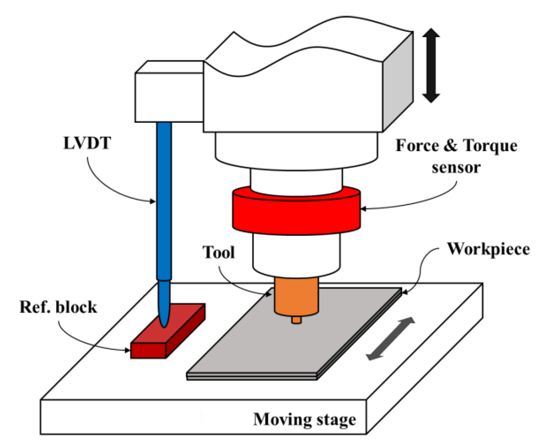
Figure 3.
Measured plunge depth under the conventional position control.

Figure 4.
Plunge depth according to advance per revolution under the conventional position control.

Figure 5.
Plunge depth according to the additional offset under the offset position control (welding speed: 150 mm/min, rotation speed: 700 rpm).
Figure 5.
Plunge depth according to the additional offset under the offset position control (welding speed: 150 mm/min, rotation speed: 700 rpm).

Figure 6.
Measured profiles of the plunge depth and axial force under the offset position control (welding speed: 150 mm/min, rotation speed: 700 rpm, offset: 0.35 mm).
Figure 6.
Measured profiles of the plunge depth and axial force under the offset position control (welding speed: 150 mm/min, rotation speed: 700 rpm, offset: 0.35 mm).
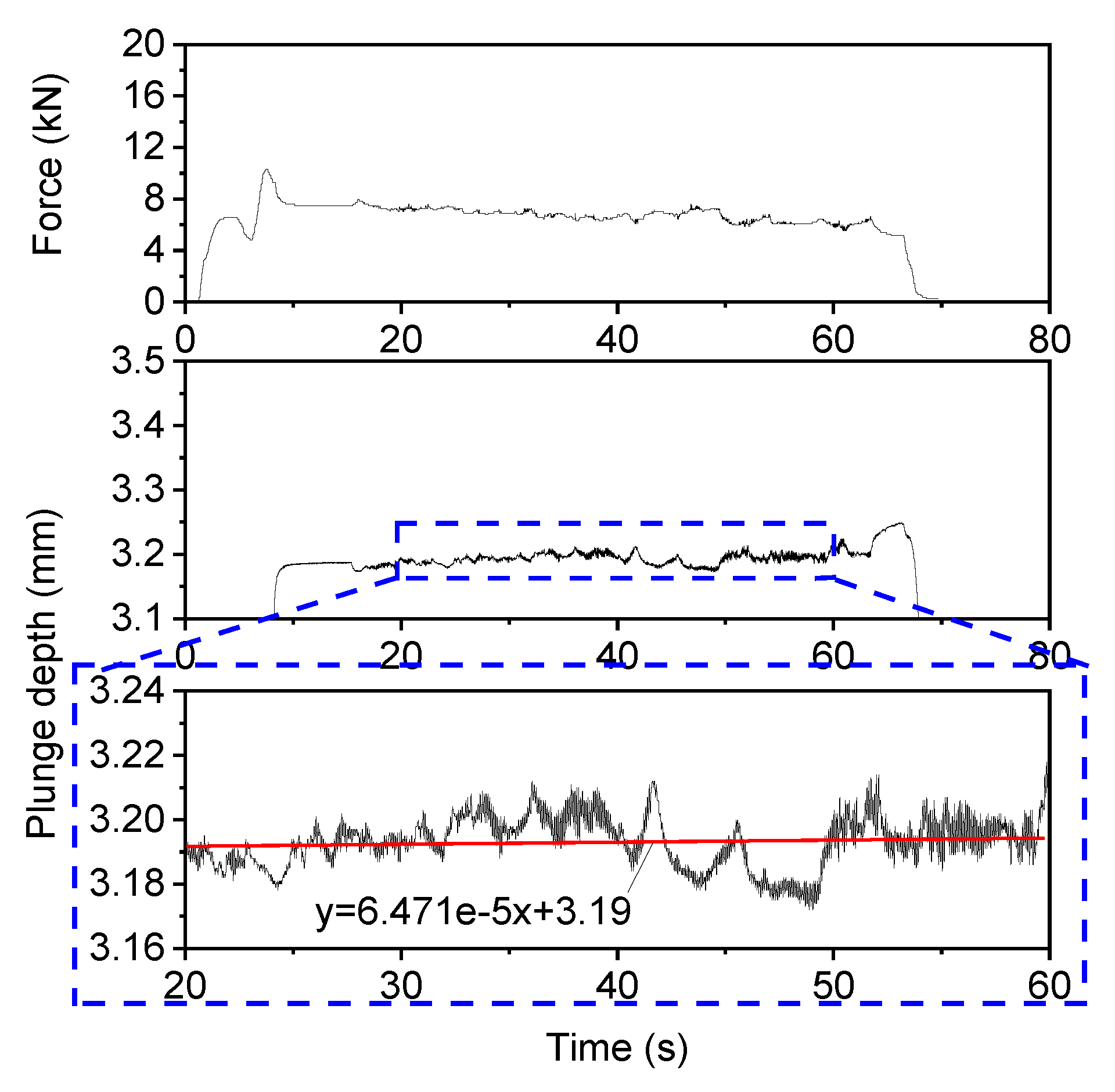
Figure 7.
Tensile shear test results according to the location of specimens under the offset position control; (a) fracture load; (b) specimen preparation (welding speed: 150 mm/min, rotation speed: 700 rpm, offset: 0.35 mm).
Figure 7.
Tensile shear test results according to the location of specimens under the offset position control; (a) fracture load; (b) specimen preparation (welding speed: 150 mm/min, rotation speed: 700 rpm, offset: 0.35 mm).

Figure 8.
Measured profiles of the plunge depth and axial force under the deflection compensation control (welding speed: 150 mm/min, rotation speed: 700 rpm, offset: 0.35 mm).
Figure 8.
Measured profiles of the plunge depth and axial force under the deflection compensation control (welding speed: 150 mm/min, rotation speed: 700 rpm, offset: 0.35 mm).

Figure 9.
Measured plunge depth under the deflection compensation control.

Figure 10.
Plunge depth according to advance per revolution under the deflection compensation control.
Figure 10.
Plunge depth according to advance per revolution under the deflection compensation control.

Figure 11.
Tensile shear test results under the deflection compensation control according to the location of specimens (welding speed: 150 mm/min, rotation speed: 700 rpm, offset: 0.35 mm).
Figure 11.
Tensile shear test results under the deflection compensation control according to the location of specimens (welding speed: 150 mm/min, rotation speed: 700 rpm, offset: 0.35 mm).
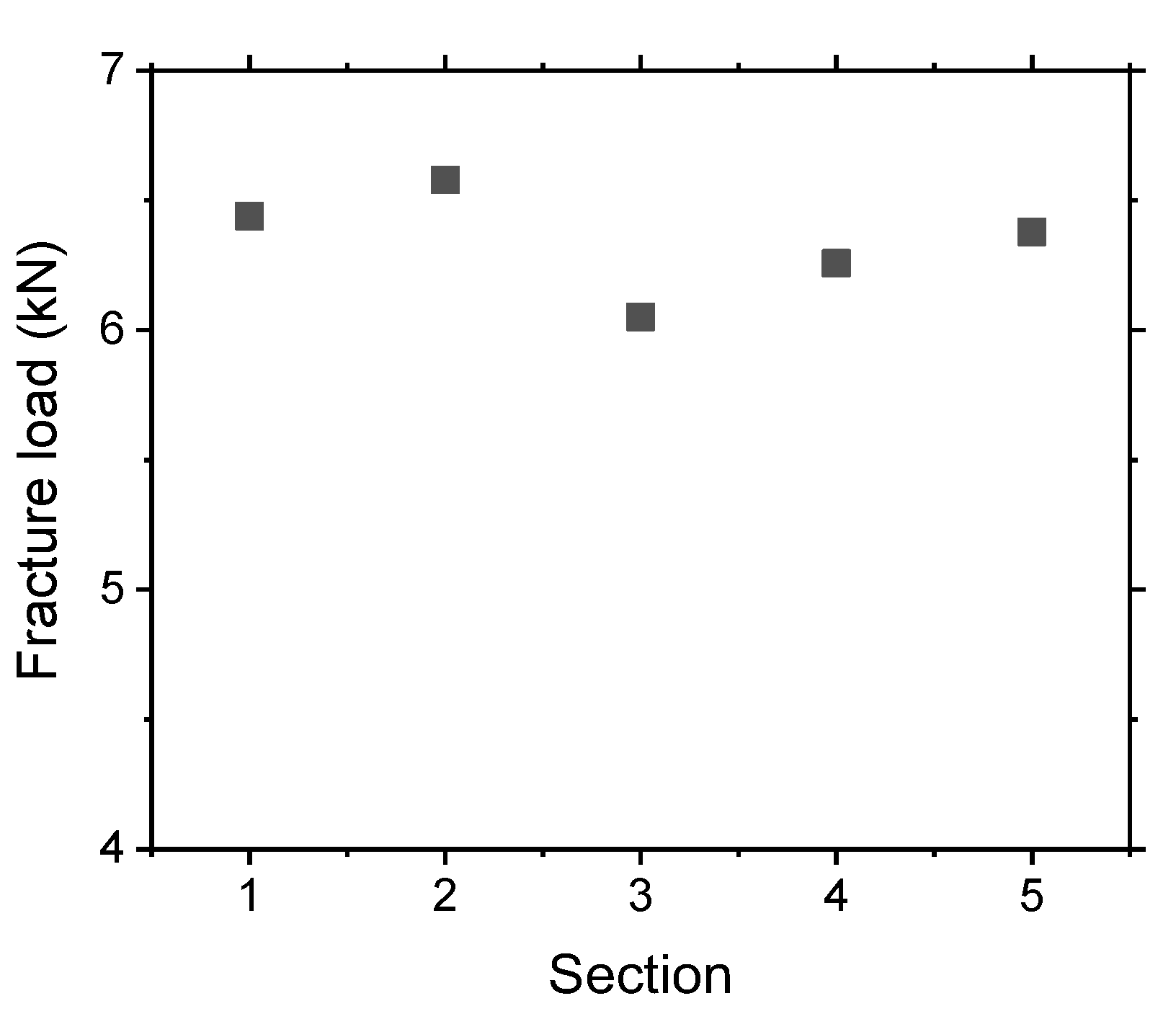
Figure 12.
Axial force and torque according to advance per revolution under the deflection compensation control.
Figure 12.
Axial force and torque according to advance per revolution under the deflection compensation control.


Table 1.
Chemical composition of base materials (wt%).
| Al 5083-O | |||||||||||
| Si | Fe | Cu | Mn | Mg | Cr | Zn | Ti | Al | |||
| 0.14 | 0.26 | 0.04 | 0.69 | 4.54 | 0.11 | 0.01 | 0.02 | Bal. | |||
| DP 590 | |||||||||||
| C | Si | Mn | P | S | Fe | ||||||
| 0.078 | 0.362 | 1.809 | 0.0172 | 0.0014 | Bal. | ||||||
© 2019 by the authors. Licensee MDPI, Basel, Switzerland. This article is an open access article distributed under the terms and conditions of the Creative Commons Attribution (CC BY) license (http://creativecommons.org/licenses/by/4.0/).
Share and Cite
MDPI and ACS Style
Yoon, J.; Kim, C.; Rhee, S. Performance of Plunge Depth Control Methods During Friction Stir Welding. Metals 2019, 9, 283. https://doi.org/10.3390/met9030283
AMA Style
Yoon J, Kim C, Rhee S. Performance of Plunge Depth Control Methods During Friction Stir Welding. Metals. 2019; 9(3):283. https://doi.org/10.3390/met9030283
Chicago/Turabian StyleYoon, Jinyoung, Cheolhee Kim, and Sehun Rhee. 2019. "Performance of Plunge Depth Control Methods During Friction Stir Welding" Metals 9, no. 3: 283. https://doi.org/10.3390/met9030283
Note that from the first issue of 2016, this journal uses article numbers instead of page numbers. See further details here.