Properties of Components with Incrementally Formed Gears


Institute of Forming Technology and Lightweight Components, TU Dortmund University, Baroper Str. 303, 44227 Dortmund, Germany
*
Author to whom correspondence should be addressed.
Metals 2019, 9(5), 515; https://doi.org/10.3390/met9050515
Submission received: 15 April 2019
/
Revised: 27 April 2019
/
Accepted: 29 April 2019
/
Published: 1 May 2019
Abstract
:The process class of sheet-bulk metal forming (SBMF) involves several advantages for the manufacture of functional components. Its incremental variant (iSBMF) enables a very flexible dimensioning of components. To treat the unfavorable manufacturing time of the incremental approach, this investigation is focused on an alternative process route using rotating forming tools, which decrease the process time significantly. After an analysis of the mechanical properties as well as the micro- and macroscopic surface quality, a quasi-static benchmark test was performed. Normalized by the weight of the component, gears manufactured by iSBMF and BS600 steel presented the same load capacity as gears manufactured by blanking with subsequent hardening. Here, using innovative high strength steels with a significant strain hardening behavior like high manganese steels enables for weight-reduced gears.
1. Introduction
Climate change leads to significantly growing ecological requirements. In the case of automotive engineering, this means a distinct reduction of CO2-emissions. Here, the reduction of accelerated masses offers one option to decrease pollution. Lightweight design requires the manufacture of highly functionally integrated components combining a high load capacity with a weight reduction of the components [1]. The requirements for a large batch production of load-adapted components under ecological aspects calls for new manufacturing processes to increase the material efficiency and to decrease the number of subsequent process stages, for instance heat treatment or descaling. Here, especially gearbox components like synchronizer rings and starter gears (Figure 1a) or safety components like seat adjusters (Figure 1b) offer a high potential for improvement. The fine blanking process of seat adjusters described by Mori et al. [2] leads to a reduced usable sheet thickness (Figure 1b) because of the characteristic rollover [3]. Other conventional manufacturing processes for those parts are bulk forming or joining [4]. Manufacturing functional components with a load-adapted shape utilizing these conventional processes leads to several disadvantages. A poor material efficiency, a uniform thickness distribution and the need for supersized forming presses are some of them. Furthermore, voids in the weld joint or discontinuous material fiber after the milling of functional elements can impair the load capacity and thus, the life span of the product [5]. Due to the potentials of additive manufacturing, a local adjustment of the sheet thickness by laser additive manufacturing was investigated [6]. Here, the process time and the cost per component increase significantly. In contrast, the manufacturing of load-adapted gears by sheet-bulk metal forming (SBMF) [7] and respectively plate forging [8] offers a suitable approach to avoid the above-mentioned disadvantages. The application of bulk forming operations on sheet metals enables a three dimensional material flow [9]. Thus, a local adaption of the sheet thickness, tailored to the load expected during the later application, is possible. Additionally, the strain hardening of the processed sheet can be utilized advantageously. An even more flexible subcategory of SBMF is the incremental sheet-bulk metal forming (iSBMF). In this case, the forming forces are independent of the final component’s size due to a locally restricted forming zone. Furthermore, the feature of kinematic shaping leads to high geometrical flexibility.
Friese [10] invented the technology of edge thickening by iSBMF and transferred it into an industrial application for the forming of semi-finished starter-gears with a load-adapted shape. For this purpose, an axially clamped sheet rotates around its axis while a forming tool indents radially. Due to the diameter reduction, the sheet thickness in the edge zone is increased. Current investigations in this field are focused on the impact of process parameters on the main defects occurring in an incremental edge thickening process [11]. For the later application, the final shape of the gear geometry is finished subsequently by milling processes. This processing calls for a subsequent heat treatment to adjust the mechanical properties of the gear. At present, an advantageous forming of the functional gear elements by iSBMF is not efficient due to a long process time and a short tool life. To set the stage for an industrial use of gear forming by iSBMF, Wernicke et al. [12] decreased the duration of the incremental process by using rotating gearing tools.
An important aspect of the iSBMF is the utilization of strain hardening for the adjustment of the mechanical product properties. This aspect has not been investigated yet. The knowledge of the resulting mechanical properties is essential, especially for an optimal dimensioning of the component. Thus, the focus of this paper is the identification of the impact of two different incremental gear-forming processes on the product properties. Furthermore, the influence of the rotational speed of the forming tool, as well as additional lubrication, are investigated. Due to the long calculating time for a numerical modelling of the iSBMF-processes, the presented results are mainly based on experimental investigations. The evaluation of the results occurs by Vickers hardness measurements (HV0.1) and a prototypical gear strength test.
2. Mechanical Characterization
The process design for the manufacture of load adapted components requires the knowledge of the material’s strain hardening behavior. Therefore, a comprehensive mechanical characterization of the utilized sheet materials, a bainitic steel (BS600) and an innovative high-manganese steel (H-Mn) with an initial thicknesses of t0 = 2 mm is essential. Gröbel et al. [13] numerically determined the effective strain φ resulting in SBMF components to be larger than 4. To obtain a more precise extrapolation of the flow curves in-plane torsion tests, in accordance with Traphöner et al. [14], are carried out. This test enables a material characterization with effective strains higher than in tensile or compression tests (Figure 2a). Both materials show a different strain hardening behavior. The flow stress values of the H-Mn steel are almost double compared to the BS600 steel. With an application of these materials to iSBMF-processes and effective strains of φ > 4 especially the H-Mn steel offers a high potential of strongly hardened component areas, which can be used for functional elements without the need for subsequent heat treatment.
An overview on the most important material parameters determined by the uniaxial tensile test is shown in Table 1.
To take into account the aimed increase of forming velocity, stack compression tests with strain rates up to = 40 s−1 were carried out (Figure 2b). This acceleration also raises the resulting workpiece temperature within the forming process. Temperatures up to 300 °C were identified by numerical analyses taking into account the expected maximum forming velocities of the experimental setup. In this temperature range hot tensile tests were carried out (Figure 2c). In this temperature range the BS600 steel possess blue brittleness. Thus, BS600 first softens until a temperature of 200 °C, but shows a strain hardening for a further increase of the temperature. This effect may influence the iSBMF process, since for higher forming velocities the forming forces will also increase, but the mechanical properties of the product may improve correspondingly. In contrast, the geometrically restricted forming tools operate at their maximum load capacity in the case of cold forming of the high manganese material. Here, the material softens at increased strain rates as well as at increased temperatures. Therefore, the tool life in iSBMF will benefit from an increased process velocity.
3. Experimental Procedure and Results
The manufacture of load adapted components by iSBMF is based on a process route consisting of edge-thickening followed by a subsequent gear forming process. Thus, the experimentation on edge thickening is presented firstly. Afterwards, the subsequent gear forming process is presented. Finally, utilizing a quasi-static benchmark-test, the performance of gears manufactured by iSBMF is compared with that of a seat-adjuster manufactured by blanking with subsequent heat treatment.
3.1. Edge Thickening
The manufacturing of load-adapted components by iSBMF starts with the local adjustment of the sheet thickness with respect to the mechanical requirements during the later use. This preceding edge thickening step is necessary for a uniform thickness distribution between the tip and ground of the gears. Otherwise, the forming of functional elements leads to a decreasing thickness from the root to the tip of a gear. The edge thickening at the outer rim is conducted on a multi-axis forming press (Figure 3a) by the incremental process shown in Figure 3b. Here, two rotating chambering tools, featuring a circumferential cavity, clamp the blank axially with a clamping Force Fclamp = 100 kN (Figure 3b). As the workpiece rotates with a rotational speed of ω = 10°/s, an edge thickening tool (Figure 3a, axis 4a) radially indents inwards up to a total indentation of i = 5 mm and thus reduces the workpiece diameter. This tool can realize the material flow by a slipping or shifting circumferential movement as well as a clocked radial indentation with a rotational speed of ω = 0°/s (Figure 3c). These three different kinematics influence the material flow in the circumferential direction due to a variation of friction. The changed material flow leads to different effective strain distributions and consequently, the resulting local strain hardening varies. This leads to dissimilar mechanical and topological properties of the thickened edge for each process kinematic, while the thickened geometry remains constant.
The Vickers hardness-measurement enables the identification of different mechanical properties. Firstly, the determination of the standard deviation of the hardness measurement occurred on a blank of BS600-steel in delivery condition to ascertain the effect of different hardness distributions to be significant (Figure 4a). Here, the used Vickers hardness measurement presented a standard deviation of 7.4 HV0.1, which means 3.6% relative to the averaged initial hardness of the workpiece material (H0 = 208 HV0.1). Figure 4b and c present the measured hardness-increase due to different edge thickening kinematics related to the initial hardness H0. Due to the significance of the process dependent hardness distribution, the initial hardness distribution within the sheets made of high-manganese steel is assumed as homogeneous as in the sheets made of BS600-steel
Close to the thickened edge, both materials qualitatively present the same hardening behavior for the different process kinematics. This means setting up the mechanical properties at the edge of the sheet qualitatively depends much more on the process kinematic than the strain hardening behavior of the blank material. The strain hardening behavior of the workpiece material rather determines the magnitude of the hardness increase. While the slipping process results in a maximum hardness close to the surface (r → 0), the clocked process led to the opposite effect. Here, the maximum hardness was measured at a distance of 1–2 mm to the circumferential surface and decreased to the outer as well as to the inner radius. This implies that the clocked process leads to a softer edge, which can be beneficial as it decreases the tool load required during the subsequent gear forming process. In comparison, the shifting and clocked indenting edge thickening processes influenced an extended radial area by an increased hardness.
Table 2 presents a summary of the impact of different process strategies on the hardness increase ΔHmax/H0. It further presents the ratio of the radial range of influence, which is defined by the length ri that presents a changed hardness related to the indentation i of the tool.
Beside the resulting hardness distribution of a load-adapted semi-finished product, the quality of the circumferential surface is also important with respect to the subsequent forming of functional elements. Figure 5 shows the macroscopic and microscopic impact of the different thickening processes on the surface quality. Here, each process led to a characteristic surface. In case of the slipping edge thickening process, the relative velocity in circumferential direction caused a circumferential drawing of the workpiece material and, thus, near-surface tension, which resulted in grooves, cracks and voids (Figure 5a). These cracks reduced the formability of the material during the subsequent gear forming process. Furthermore, cracks, as well as voids, would decrease the load capacity of the final product during its later use. This effect was not noticeable for the shifting and clockwise indenting processes, but the clockwise indenting generated a wavy thickened surface. This wavy surface would lead to an inhomogeneous thickness distribution in the geared section and may affect the in service behavior negatively. Here, decreasing the workpiece rotation per indentation enabled a reduction of that waviness but extended the process time significantly.
In an industrial setup, lubricants are commonly used to increase the tool life. Therefore, the impact of this parameter on the edge thickening process was investigated. For this purpose a lubricant with a high-pressure absorption capability (CLF-400E) and a less viscous deep-drawing oil (Drylub WA 03T, both Raziol® Zibulla & Sohn GmbH), were applied during the process continuously. For this analysis, the shifting process was chosen because it presented the most relevance to industry, after the macro- and microscopic investigation on the surface quality. The surface quality resulting from the other edge thickening processes did not improve significantly with the application of a lubricant. Figure 6a presents the impact of both lubricants on the forming force during the shifting edge thickening process compared to the forming force Fdry of the non-lubricated process. Here, the deviation of the resulting thickness t1 of the thickened rim compared to the dry formed components was also taken into account (Figure 6b). While the application of lubrication led to a general reduction of the tangential forming force Ft, a significant change of the radial forming force Fr was not detectable. Despite the high contact stresses occurring in incremental sheet bulk metal forming processes, an essential difference between the high and low viscous lubricants was not identifiable.
Figure 6c presents the impact of the lubricated iSBMF edge thickening process with an increased rotational speed ω on the resulting hardness distribution. Due to the increased forming power, the workpiece material heated up and strain hardening decreased. The reduced strain hardening yielded a lower forming force during edge thickening as well as for a subsequent gear forming process. A rough determination of the temperature at the surface of the thickened edge by a thermographic camera was done. At a rotational speed of ω = 500°/s, the temperature raised up to 80 °C in the case of BS 600 steel. The contact of the workpiece with the surrounding chambering tools at the end of the process prevented a considerably higher increase in the temperature at the surface of the thickened rim. The effect of heating became more significant with a stronger workpiece material due to the performed plastic work and led to a drop in the radial forming force Fr of about 6% in the case of H‑Mn steel (Figure 6a).
Table 3 lists the qualitative impact of the process parameters indentation per revolution ipr, rotational speed ω and lubrication for each process strategy on the resulting surface quality. While the rotational speed only influenced the surface quality at the slipping edge thickening process, a general improvement of the surface quality was achievable by decreasing the indentation per revolution or adding lubrication. The tests contained rotational speeds in the range between ω = 10°/s and 1800°/s, while the slipping process was stopped at 180°/s due to the heating of the forming tool. The coefficients describing the indentation per revolution were in a range between 0.1 mm/rev and 1 mm/rev.
3.2. Gear Forming
The presented edge thickening processes enabled the manufacture of load-adapted semi-finished components. To realize a functional component, for instance for torque transmission, a subsequent gear forming process was necessary. Due to the advantageous mechanical properties and surface quality, the shifting edge thickening process was used as a preceding process for the following investigations on gear forming. With the flexibility of the iSBMF, two different gear-forming processes were possible—the clocked indenting [15] and the rotating gear forming [12]. For both processes, a sheet was clamped axially with a cavity surrounding the formed area (Figure 7a).
During the radial feeding of the clocked indenting gear forming tool, the workpiece material flowed into axial and radial direction resulting in the shape of a gear (Figure 7b-1). Due to the long process time of the clocked indenting procedure, the rotating gear forming process (Figure 7b-2) could achieve a higher profitability. Based on this rotating gear forming process, Wernicke et al. [12] accelerated the gear forming process by a factor of fifty.
In the case of prototyping, the availability of both processes enables the manufacture of geometrically identical functional components with different mechanical properties. In addition to the kinematic of the process, the impact of an increased process velocity was investigated. Figure 8a presents the hardness distribution of a rotationally formed gear element without a previous edge thickening (t = t0 = 2 mm). These results were based on measuring along a path at five different sections of each gear made of BS600 steel. Here, a very inhomogeneous hardness distribution between the different sections was visible. The gear forming occurred by a material flow surrounding the ground of the gear. The remaining material underwent less or no plastic strain and thus presented no significant increase of hardness in the tip of the final gear (Figure 8a, section 1). In comparison, Figure 8b,c show the results of both gearing processes with a preceding thickening step (t0 = 2 mm → t1 = 5 mm). This preforming homogenized the hardness distribution in the final gear and led to a significantly increased hardness, also in the gear tip. Furthermore, a preceding shifting edge thickening increased the hardness at the flanks of the gear by 10% independent of the process strategy and thus improved the wear resistance of the gear during the later use. In contrast, the clocked indenting gear forming using blanks thickened by the shifting route (Figure 8c) led to less homogeneous hardness distribution within the gears. Here, the difference between rotating and clocked indenting gears was caused by the superposed circumferential material flow of the rotating gear forming process, as shown by Wernicke et al. [12]. This superposed material flow was based on the changing pitch cycle diameter of the workpiece. This decreasing pitch cycle diameter led to different circumferential velocities during the gear forming process using rotating tools. While the angular velocity of the tool was kept constant, a torque occurred, which led to a circumferential material flow.
Table 4 presents an overview of the process parameters and the process strategies and their impact on the hardness distribution of a gear made of BS600 steel. As an additional process parameter the impact of the radial feeding of the rotating tool was investigated. Here, continuous feeding during the workpiece rotation and a stepwise feeding with a temporary interruption of the workpiece rotation were carried out. The change of hardness ΔHmax/H0 presents the difference of the maximum value Hmax measured in each blank related to the initial hardness H0 of the workpiece material. It can be seen that continuously, as well as stepwise feeding during rotating gear forming, more or less led to equivalent mechanical properties. In contrast to the rotating processes, the clocked indenting gear forming results in different mechanical properties related to the level of strain hardening and its distribution. In the range of feasible indentation velocities (vi = 0.1–33 mm/s) only the hardness of gears manufactured by the clocked indenting process was influenced.
The increase of the rotational speed ω influenced the resulting hardness of the gears produced by rotating gear forming, while this parameter did not exist for the clocked indenting process. Due to the torque curve of the utilized motor driving the gear forming tool, the maximum rotational speed during the investigation was limited to ωmax = 180°/s. Compared to experiments with a rotational speed of ω = 45°/s, this slightly increased rotational speed resulted in an averaged hardness drop of about 12%. This hardness drop starts at a radial distance of r = 2 mm from the surface, whereas the hardness at the first 2 mm had not been influenced. Here the forming zone heated up like in the edge thickening process and counteracted the effect of strain hardening in an area where the potential of strain hardening had not been exhausted yet. The average temperature during this rotating gear forming process, using a rotational speed of ω = 180°/s, was almost homogeneous and was numerically determined to be 200 °C. Here, the numerical model described by Wernicke et al. [12] was used. This model was based on the Marc-code implemented in the commercial software Simufact Forming 15 using hexahedron elements. The resulting strain-rate = 0.44 s−1 led to the maximum temperature of 350 °C, which was measured only at the surface of the gear root. Regarding the presented material parameters characterized at increased temperatures (Figure 2c), the resulting temperature during the rotating gear forming process reduced the strength of the workpiece material in the order of 4% and 16%, for BS600 and H-Mn, respectively. Nevertheless, this slightly influenced strength caused a reduction of the necessary radial forming force Fr of about 35%. This increased rotational speed indicates an extended tool life but a declined hardness of the gear elements, whereas the formed geometry retains.
Regarding the impact of the product properties by different process routes, iSBMF of gears enables the manufacture of geometrically identical components with different mechanical properties. The presented results enable the process design and a prediction of the resulting mechanical properties. Thus, by applying this innovative technology the process chain can be selected depending on the requirements of the final component and batch size.
3.3. Benchmark-Test
For an evaluation of the obtained results and their impact on the in service behavior, gears produced by iSBMF were compared with an industrial mass-produced component. For this purpose, a quasi-static experimental setup was designed, which allows the application of torque on single gear elements (Figure 9). The setup was built on a universal testing machine (Zwick100, Zwick, Ulm, Germany) and the clamping force FClamp was raised by the traverse to a constant value of 95 kN. Subsequently, a rotation with an angular velocity of ωRot = 0.1°/s was applied on the sample. To identify the isolated torque-distortion behavior without interferences from surrounding gears, the samples were prepared to have just one single gear element engaged. Within the experiments, the prevailing torque T and the angular distortion α until fracture were measured and compared.
As a component with great potential for a load adaption as well as to be manufactured by iSBMF an industrial seat adjuster (Faurecia Seating GmbH) made of 42CrMo4-steel was compared to the gears manufactured by iSBMF. This industrial component had a homogeneous sheet thickness of t0 = 5.1 mm. It was manufactured by fine blanking and was heat treated subsequently to obtain the desired mechanical properties. With a modulus of mtest = 2.44 mm, these parts were bigger than the previously presented, which have a modulus of m = 1.5 mm. Thus, a comparison was difficult. Therefore, adequate demonstrator geometry was manufactured by sheet-bulk metal forming with a similar pitch cycle diameter and a similar modulus mtest made of 3 mm-thick BS600-steel. The initial thickness of t0 = 3 mm was edge thickened to t1 = 5 mm in the region of the final gear elements. To determine the influence of the changed sheet thickness on the mechanical properties firstly both materials were characterized with an initial sheet thickness of t0 = 3 mm. Here, in the case of the 3 mm-thick sheets the initial yield stress σY dropped by 11% (BS600) and 12% (H-Mn), whereas the strain hardening behavior of both materials remains almost unchanged. A subsequent heat treatment of the formed gears was not conducted. Due to the increased modulus and the maximum load capacity of the forming press, the subsequent gear forming occurred by the clocked indenting procedure. Here, the number of gear elements in mesh was less than in rotating gear forming. The evolution of the achieved maximum torque T corresponding to the distortion angle α until fracture of the gear elements is shown in Figure 10a.
The curves of the demonstrators were steeper at the beginning, which can be attributed to improved fiber course and strain hardening distribution, since there was no significant deviation of young’s modulus and geometry. However, for the single gear elements, failure already occurred for lower values of torque T and distortion α. Here, the maximum torque T transmitted by the iSBMF demonstrator amounts for only 70% of the reference product. Between the different process-routes, geared only vs. thickened and geared, an increase of around 10% resulted because of the preceded thickening process.
After several repetitions of the benchmark test, it was recognizable, that the industrial components had a higher standard deviation regarding the maximum torque of around 25%. Furthermore, failure at the conventionally manufactured components occurred unannounced. This fact leads to the need for an oversizing of the conventionally manufactured parts. In comparison, the standard deviation for the edge thickened and geared as well as for the geared only iSBMF-components was less than 10%. In contrast to the industrial component, failure occurred gently by a distortion of several degrees. In the case of iSBMF components, this enables for a decreased oversizing of the product.
By considering the load capacity of iSBMF components (Figure 10a) and the option of iSBMF-processes to adjust the local sheet thickness very flexible, a normalized comparison (Figure 10b) is obvious. Thus, for a given load the flexibility of the process can be used for a slight adaption of the local sheet thickness in the section, which later exhibits gear elements. Here, a slight increase in the sheet thickness could be realized by a higher indentation i of the thickening tool, whereas a significant increase of the sheet thickness calls for different chamber and thickening tools. Thereby, in Figure 10b the measured torque was related to the weight of each component. Based on this comparison iSBMF-components offer comparable maximal torques combined with a higher stiffness and thus they are competitive to the established industrial components. The elimination of the heat treatment step increased the economic efficiency of the process. This adaption would align the load capacity of the iSBMF to the conventional products, whereas the strongly localized thickening only increased the components weight marginally.
Due to the technologically restricted machine forces, processing the H-Mn high strength steel with a modulus of mtest = 2.44 mm was not successful. To classify and compare this steel grade with gears made of BS600 (Figure 10b), geared only samples with a modulus of m = 1.5 mm and a pitch cycle diameter of dP = 93 mm were manufactured. Thus, Figure 11a depicts the experimental torque-distortion-curves of the different steel grades. It is recognizable, that gear elements of both materials at the beginning present a similar torque-distortion behavior. Furthermore, the geared only samples of H-Mn could transmit a maximum-torque identical to the edge thickened and geared sample made of BS600 steel. This implies that for the same intended load capacity of iSBMF gears, the use of a steel with a significant strain hardening behavior and a high maximum hardness can make the preceded edge thickening process unnecessary. Thus, a further reduction of the process time is possible, whereas the workpiece material becomes even more expensive.
An overview of the required maximum radial forming force Fr at the end of the gear forming process is shown in Figure 11b. Due to the increased edge-thickness and the resulting strain hardening, the gear forming of edge thickened parts made of BS600 requires a forming force, which is 50% higher compared to the gear forming of sheets without preceding edge thickening. This effect can be reduced by decreasing the difference between initial sheet thickness t0 = 2 mm and the final thickness in the thickened section (t = 5 mm).
4. Conclusion and Outlook
iSBMF of gears enables resource efficient manufacturing of functional components with a load adapted shape. To allow for an industrial application of iSBMF processes the process time needs to decrease for example by the utilization of rotating forming tools. An impact of the speedup of the forming process on the product properties is noticed, which can be attributed to the changed material flow and the heating of the workpiece. Here, edge thickening with slipping tools presented the highest hardness increase whereas the surface quality became worst. Thus, edge thickening with shifting gears generates the most promising product properties for the subsequent gear forming process. Furthermore, preceding edge thickening in the section of the later gears leads to a more homogeneous hardness increase, while just gear formed elements only exhibit a near-surface hardness increase. A further homogenization of the hardness distribution can be achieved by rotating gear forming. In contrast, the clocked indenting process leads to a reduced hardness at the tip and the flanks of the gear.
The evaluation using a quasi-static benchmark test has shown that iSBMF components present a smaller load capacity than hardened components with a uniform sheet thickness manufactured industrially. Relating the load capacity to the weight of the components illustrates iSBMF components offer the same load capacity but a stiffer torque-distortion behavior. Thus, subsequent heat treatment as well as descaling processes can be avoided.
Further investigations should be focused on an additional decrease of the process time by axially chambered tools with an adjustable gap. In contrast to the current edge thickening process, edge thickening with higher thickening ratios t0/t1 can be realized in one forming step without buckling.
Author Contributions
Conceptualization, S.W.; funding acquisition, P.S. and A.E.T; investigation, S.W. and P.S.; project administration, S.W. and A.E.T.; methodology, S.W.; validation, S.W., P.S. and S.G.; writing—original draft preparation, S.W.; writing—review and editing, S.W., P.S., S.G., A.E.T., supervision, A.E.T.
Funding
This research was funded by the German Federation of Industrial Research Associations (AiF), research project No. 18663 N/1 “Economic Manufacturing of Weight- and Load Adapted Functional Components by Incremental Sheet-Bulk Metal Forming”.
Acknowledgments
The authors would like to thank the German Federation of Industrial Research Associations (AiF) for funding the research project No. 18663 N/1 “Economic Manufacturing of Weight- and Load Adapted Functional Components by Incremental Sheet-Bulk Metal Forming”. The support of the Research Association for Steel Application (FOSTA) is gratefully acknowledged. We acknowledge financial support by Deutsche Forschungsgemeinschaft and Technische Universität Dortmund/TU Dortmund University within the funding programme Open Access Publishing.
Conflicts of Interest
The authors declare no conflict of interest.
References
- Kleiner, M.; Geiger, M.; Klaus, A. Manufacturing of lightweight components by metal forming. CIRP Annals 2003, 52, 521–542. [Google Scholar] [CrossRef]
- Mori, K.; Maeno, T.; Tsuchiya, M.; Nanya, T. Inclusion of hot stamping operations in progressive-die plateforging of tailored high strength gear part. Int. J. Adv. Manuf. Technol. 2017, 90, 3585–3594. [Google Scholar] [CrossRef]
- Birzer, F. Feinschneiden und Verfahrenskombinationen auf Feinschneidpressen. In Neuere Entwicklungen in der Massivumformung; MAT-INFO Werkstoff-Informationsgesellschaft: Fellbach, Germany, 2013; pp. 105–117. [Google Scholar]
- Behrens, B.-A.; Bistron, M.; Schäfer, F. Optimierung der Prozesskette beim Präzisionsschmieden von Zahnrädern durch Verschleißreduzierung. In Neuere Entwicklungen in der Massivumformung; MAT-INFO Werkstoff-Informationsgesellschaft: Fellbach, Germany, 2007; pp. 185–204. [Google Scholar]
- Gu, H.; Yin, G.; Shulkin, B. Laser beam welding of nitride steel components. Phys. Proc. 2011, 12, 40–45. [Google Scholar] [CrossRef]
- Bamberg, M.; Sviridov, A.; Weisheit, A.; Schleifenbaum, J.H. Case studies on local reinforcement of sheet metal components by laser additive manufacturing. Metals 2017, 7, 113. [Google Scholar]
- Merklein, M.; Allwood, J.M.; Behrens, B.-A.; Brosius, A.; Hagenah, H.; Kuzman, K.; Mori, K.; Tekkaya, A.E.; Weckenmann, A. Bulk forming of sheet metal. CIRP Annals 2012, 61, 725–745. [Google Scholar] [CrossRef]
- Mori, K.; Nakano, T. State-of-the-art of plate forging in Japan. Prod. Eng. Res. Dev. 2016, 10, 81–91. [Google Scholar] [CrossRef]
- Oyachi, Y.; Allwood, J.M. Characterizing the class of local metal sheet thickening processes. In Proceedings of the Steel Research International, 10th International Conference on Technology of plasticity (ICTP), Aachen, Germany, 25–30 September 2011; pp. 1025–1030. [Google Scholar]
- Friese, U. Vorrichtung zur Herstellung eines außen verzahnten Getriebeteiles. German Patent DE 43 35 505 C1, 19 October 1993. [Google Scholar]
- Jin, J.-S.; Wang, X.-Y.; Li, L. A sheet blank rotary forging process for disk-like parts with thickened rims. J. Mech. Sci. Technol. 2016, 30, 2723–2729. [Google Scholar] [CrossRef]
- Wernicke, S.; Sieczkarek, P.; Grodotzki, J.; Gies, S.; Ben Khalifa, N.; Tekkaya, A.E. Material flow analysis for the incremental sheet-bulk gearing by rotating tools. In Proceedings of the ASME 2017 12th International Manufacturing Science and Engineering Conference collocated with the JSME/ASME 2017 6th International Conference on Materials and Processing, Los Angeles, CA, USA, 4–8 June 2017. [Google Scholar] [CrossRef]
- Gröbel, D.; Schulte, R.; Hildenbrand, P.; Lechner, M.; Engel, U.; Sieczkarek, P.; Wernicke, S.; Gies, S.; Tekkaya, A.E.; Behrens, B.A.; et al. Manufacturing of functional elements by sheet-bulk metal forming processes. Prod. Eng. Res. Devel. 2016, 10, 63–80. [Google Scholar] [CrossRef]
- Traphöner, H.; Heibel, S.; Clausmeyer, T.; Tekkaya, A.E. Influence of manufacturing processes on material characterization with the grooved in-plane torsion test. Int. J. Mech. Sci. 2018, 146, 544–555. [Google Scholar] [CrossRef]
- Sieczkarek, P.; Isik, K.; Ben Khalifa, N.; Martins, P.A.F.; Tekkaya, A.E. Mechanics of sheet-bulk indentation. J. Mat. Proc. Technol. 2014, 214, 2387–2394. [Google Scholar] [CrossRef]
Figure 1.
Conventionally manufactured functional components: (a) starter gear (Winkelmann) and (b) seat-adjuster (Faurecia).
Figure 1.
Conventionally manufactured functional components: (a) starter gear (Winkelmann) and (b) seat-adjuster (Faurecia).

Figure 2.
(a) Flow curves of the investigated materials and their extrapolation with different approaches (in-plane torsion test at room temperature), (b) influence of increased strain rates (stack compression tests at room temperature) and (c) increased temperatures (hot tensile tests, in rolling direction) on the material behavior (t0 = 2 mm).

Figure 3.
(a) Multi-axis forming press and (b) schematically cross-section of the edge thickening by (c) different edge thickening processes.
Figure 3.
(a) Multi-axis forming press and (b) schematically cross-section of the edge thickening by (c) different edge thickening processes.
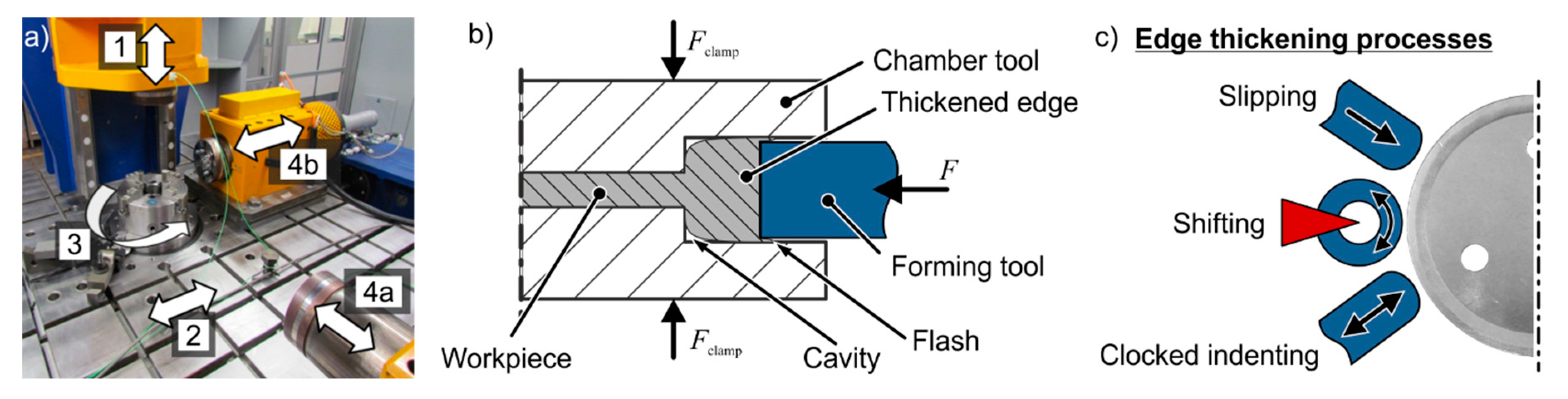
Figure 4.
Hardness distribution of the (a) initial sheet and edge thickened (b) BS600 and (c) H-Mn sheets, respectively.
Figure 4.
Hardness distribution of the (a) initial sheet and edge thickened (b) BS600 and (c) H-Mn sheets, respectively.

Figure 5.
Characteristic influence of the (a) slipping, (b) shifting and (c) clocked indenting edge thickening processes on the macro- and microscopic surface quality of sheets made of H-Mn.
Figure 5.
Characteristic influence of the (a) slipping, (b) shifting and (c) clocked indenting edge thickening processes on the macro- and microscopic surface quality of sheets made of H-Mn.

Figure 6.
Impact of rotational speed and lubrication on the (a) forming force F (b) related to the sheet thickness and (c) hardness distribution H at the shifting process.
Figure 6.
Impact of rotational speed and lubrication on the (a) forming force F (b) related to the sheet thickness and (c) hardness distribution H at the shifting process.

Figure 7.
(a) Setup of rotating gear forming. (b) Clocked indenting and rotating process strategies for the incremental sheet-bulk metal gear forming processes.
Figure 7.
(a) Setup of rotating gear forming. (b) Clocked indenting and rotating process strategies for the incremental sheet-bulk metal gear forming processes.

Figure 8.
Hardness distribution in gears made of BS 600 steel (H0 = 208 HV0.1) after gear forming with (a) a rotating tool without edge thickening, (b) and (c) with preceded edge thickening but different gear forming strategies.
Figure 8.
Hardness distribution in gears made of BS 600 steel (H0 = 208 HV0.1) after gear forming with (a) a rotating tool without edge thickening, (b) and (c) with preceded edge thickening but different gear forming strategies.

Figure 9.
Setup of the benchmark-test.

Figure 10.
(a) Torque-distortion-curves of conventionally manufactured industrial seat adjusters and demonstrators manufactured by incremental sheet-bulk metal forming (iSBMF). Both with modulus mtest = 2.44 mm, (b) torque-distortion-curves normalized by the weight of the component.
Figure 10.
(a) Torque-distortion-curves of conventionally manufactured industrial seat adjusters and demonstrators manufactured by incremental sheet-bulk metal forming (iSBMF). Both with modulus mtest = 2.44 mm, (b) torque-distortion-curves normalized by the weight of the component.

Figure 11.
(a) Torque-distortion-curves and (b) comparison of the maximal radial forming force Fr of gears made of different steel grades with modulus m = 1.5 mm.
Figure 11.
(a) Torque-distortion-curves and (b) comparison of the maximal radial forming force Fr of gears made of different steel grades with modulus m = 1.5 mm.


Table 1.
Material parameters of BS600 and high-manganese (H-Mn) steel in t0 = 2 mm determined by tensile tests.
Table 1.
Material parameters of BS600 and high-manganese (H-Mn) steel in t0 = 2 mm determined by tensile tests.
| Material Parameter | BS600 | H-Mn | ||||
|---|---|---|---|---|---|---|
| 0° | 45° | 90° | 0° | 45° | 90° | |
| E-Modulus E (GPa) | 219.67 | 199.00 | 223.33 | 199.33 | 195.33 | 207.50 |
| Tensile strength Rm (MPa) | 613.00 | 587.33 | 613.67 | 883.67 | 866.00 | 896.50 |
| Yield strength Rp0,2 (MPa) | 502.67 | 531.00 | 559.33 | 510.67 | 510.00 | 512.50 |
| Fracture strain εf (%) | 6.35 | 5.86 | 6.19 | 44.33 | 44.83 | 39.57 |
| Hardening exponent n (-) | 0.08 | 0.06 | 0.05 | 0.07 | 0.08 | 0.09 |
| Lankford coefficient r (-) | 0.54 | 0.96 | 0.75 | 0.57 | 0.92 | 1.02 |
Table 2.
Maximum hardness increase depending on the process strategy and ratio of influenced radius ri to total indentation i.
Table 2.
Maximum hardness increase depending on the process strategy and ratio of influenced radius ri to total indentation i.
| Process Strategy | BS600 | H-Mn | ||
|---|---|---|---|---|
| ΔHmax/H0 | Influenced Radius ri/Total Indentation i | ΔHmax/H0 | Influenced Radius ri/Total Indentation i | |
| Slipping | +60% | ca. 6 mm/4 mm = 1.5 | +90% | ca. 8 mm/4 mm = 2 |
| Shifting | +40% | +79% | ||
| Clocked indenting | +19% | +50% | ||
Table 3.
Qualitative impact of the key process parameters on the surface quality.
| Process Strategy | Increase of Indent./Rev. | Increase of Rotational Speed | Addition of Lubricant |
|---|---|---|---|
| Slipping | ↓ | ↓ | ↑ |
| Shifting | ↓ | - | ↑ |
| Clocked | ↘ | - | - |
| ↑—Improvement; ↓—Worsening; -—No influence | |||
Table 4.
Impact of process parameters and gear forming strategies on the hardness of the gears made of BS600 steel.
Table 4.
Impact of process parameters and gear forming strategies on the hardness of the gears made of BS600 steel.
| Parameter | Gear Forming Strategy | |||||
|---|---|---|---|---|---|---|
| Clocked Indenting | Rotating (Continuously) | Rotating (Stepwise) | ||||
| Without Thickening | With Thickening | Without Thickening | With Thickening | Without Thickening | With Thickening | |
| ΔHmax /H0—Tip | +18% | +48% | +54% | +56% | +57% | +57% |
| ΔHmax /H0—Flank | +23% | +38% | +39% | +40% | +31% | +37% |
| ΔHmax /H0—Ground | +47% | +53% | +34% | +55% | +38% | +53% |
| Incr. indent. velocity vi | ↑ | ↑ | → | → | → | → |
| Incr. rot. speed ω | - | - | ↓ | ↓ | ↓ | ↓ |
| Addition of Lubricant | ↑ | ↑ | → | ↑↑ | → | → |
| Incr. of indent./rev. | - | - | ↑ | ↑↑↑ | ↓↓ | ↑↑↑ |
| ↑—Improvement; ↓—Worsening; -—No influence | ||||||
© 2019 by the authors. Licensee MDPI, Basel, Switzerland. This article is an open access article distributed under the terms and conditions of the Creative Commons Attribution (CC BY) license (http://creativecommons.org/licenses/by/4.0/).
Share and Cite
MDPI and ACS Style
Wernicke, S.; Sieczkarek, P.; Gies, S.; Tekkaya, A.E. Properties of Components with Incrementally Formed Gears. Metals 2019, 9, 515. https://doi.org/10.3390/met9050515
AMA Style
Wernicke S, Sieczkarek P, Gies S, Tekkaya AE. Properties of Components with Incrementally Formed Gears. Metals. 2019; 9(5):515. https://doi.org/10.3390/met9050515
Chicago/Turabian StyleWernicke, Sebastian, Peter Sieczkarek, Soeren Gies, and A. Erman Tekkaya. 2019. "Properties of Components with Incrementally Formed Gears" Metals 9, no. 5: 515. https://doi.org/10.3390/met9050515
Note that from the first issue of 2016, this journal uses article numbers instead of page numbers. See further details here.