Article

Influence of the Alkaline Reserve of Chloride-Contaminated Mortars on the 6-Year Corrosion Behavior of Corrugated UNS S32304 and S32001 Stainless Steels

by
Asunción Bautista
*,
Francisco Velasco
and
Manuel Torres-Carrasco
Department of Materials Science and Engineering—IAAB, Universidad Carlos III de Madrid, Avda. Universidad 30, 28911 Leganés, Madrid, Spain
*
Author to whom correspondence should be addressed.
Metals 2019, 9(6), 686; https://doi.org/10.3390/met9060686
Submission received: 19 May 2019 / Revised: 12 June 2019 / Accepted: 13 June 2019 / Published: 14 June 2019
(This article belongs to the Special Issue Corrosion and Protection of Metals)

Abstract

:
The durability of two lean corrugated duplex stainless steel (UNS S32304 and S32001) bars manufactured for concrete reinforcement was studied in four different corrosive conditions. These duplex stainless steels are more economical than the most traditional, well-known duplex grade steels (UNS S32205). The research was carried out in mortar samples for six years. In half of the samples, the alkaline reserve had been previously decreased, and their pH was slightly below 12, while in the other half, the pH close to the bars remained as-manufactured. Moreover, there were samples with modified and non-modified alkaline reserve where chlorides had been previously added to the mortar which were exposed to high relative humidity. In other samples—which were partially immersed in 3.5% NaCl—the chlorides entered through the mortar by natural diffusion. The electrochemical behavior of the reinforcements in these conditions was periodically monitored through corrosion potential (Ecorr) and electrochemical impedance spectroscopy (EIS) measurements during the whole testing period. The samples were anodically polarized at the end of the exposure. The results prove that the decrease in the alkaline reserve of the mortars can affect the corrosion behavior of the studied lean duplex in environments with high chloride concentrations. The duplex microstructure of the reinforcements makes it so that the corrosion proceeds by selective attack of the phases.

1. Introduction

Stainless steels are increasingly used as reinforcement bars for concrete structures exposed to corrosive environments or with a long design life, as they have already shown high chloride concentration threshold [1] and high chemical durability when they are embedded in mortar [2,3]. Their high corrosion resistance is due to the formation of a passivating layer on their surface, which has a duplex structure [4], and whose protective properties increase with the pH of the media [5]. Moreover, stainless steels generally retain more high-temperature strength than carbon steel at temperatures above 550 °C, which is interesting for the structural design against fire [6].
As stainless-steel bars are more expensive than the usual carbon steel bars, the use of the former is limited to the most exposed regions of the structure and to high-risk elements. They are also used for the restoration of structures with artistic interest or that have already suffered severe corrosion damage a long time before the end of their expected service life [7].
Relatively good results related to the possible use of low-Cr ferritic stainless steels were published decades ago [8]. At present, the performance of low-Cr ferritic reinforcements is again under study, due to their reduced price in comparison to other grades of stainless steel [9,10,11,12]. Ferritic stainless steels can be an interesting option to assure the durability of structures in moderately corrosive environments, but other alternatives should be considered for highly aggressive conditions.
For very corrosive environments, austenitic stainless-steel grades such as UNS S30400 and S31600 were initially proposed and used as reinforcements [13]. Then, the duplex UNS S32205 appeared in the market, proving its excellent corrosion resistance in simulated concrete solutions [14,15] and in mortars [2,3].
However, several years ago, the high cost of Ni fostered the study of low-Ni grades as an alternative. Initially, low-Ni, high Mn-N austenitic stainless steels were considered [14,16,17], and more recently, the interest shifted towards the use of lean duplex grades—which also have less Ni than traditional austenitic grades. Though at this exact moment the Ni price is not as high as a decade ago and the huge economic advantages that lean duplex had against the traditional austenitic grades have been temporally reduced, the study of these grades is still interesting, because the instability in their price is always a disadvantage of high-Ni austenitic stainless steels.
Some results have suggested that UNS S32304 lean duplex steel has clearly better corrosion resistance than the austenitic S30400 steel in simulated pore solution tests [18] and in highly porous mortar [19]. Moreover, in studies carried out in solutions with high-strength bars, the results obtained for the S32304 were also better than those obtained for S30400 and S31600 [19], the lean duplex grade being cheaper than the S31600. The improvement of the durability that can be achieved using S31600 instead of S30400 [14] is foreseeably lower than that achieved using S32304 instead of S30400 [1,20]. On the other hand, the lean duplex grade UNS S32001 has proved to have a similar corrosion resistance to pitting onset than S30400 in tests in simulated concrete solutions [19], the current price of the former being slightly lower.
Lean duplex steel can also have other advantages over austenitic reinforcements. Tests carried out in solution indicate that the duplex microstructure in corrugated stainless bars favors a lower penetration of the corrosive attack and seems to be able to decrease their progress rate [20]. When formed through hot working, lean duplex steels exhibit ductility properties that give these materials advantages over carbon steel or cold-worked stainless steel reinforcements for structures located in seismic zones [21]. Moreover, duplex stainless-steel reinforcements have demonstrated suitable stress corrosion cracking behavior in tests carried out in simulated pore solutions with chlorides [15,22].
It is true that results have also been published where the corrosion behavior of lean duplex steel seemed worse than that of the traditional austenitic steels such as S30400 [23,24,25], especially when S32101 is considered. So, the interest in clarifying this controversy fosters the need for carrying out more research about the durability of these types of reinforcements. Bearing in mind that a great part of the previous research on the corrosion behavior of lean duplex steel has been carried out in solution, it is interesting to obtain more information through tests in concrete or mortar. There are factors that can meaningfully affect the corrosion behavior of reinforcements which cannot be simulated in solution tests, as has been discussed in previous publications [2].
The alkaline reserve is a key factor for the durability of the reinforcements, as the corrosion resistance of the carbon steel has proved to vary following the [Cl]/[OH]3 ratio [26]. The pH of the pore solution can not only determine the nature of the protective layer formed on the stainless-steel reinforcements [5], but also control the acidification process associated with the pit development [27]. In practice, the alkaline reserve tends to decrease progressively due to the reaction of some hydration products of the mortar with the CO2 of the air [28], and new, more ecologically-friendly cementitious materials (as many hybrid cements) have lower alkalinity in their pore solutions due to a lack of meaningful amounts of portlandite [29]. In environments with chlorides, duplex stainless steels embedded in concrete manufactured with pure CEM I have proved to show higher corrosion resistance than those embedded in concrete with 36% pozzolan in the cementitious material [30].
To date, previous studies have been carried out in fully carbonated media or in media whose pHs correspond to the one given by a saturated Ca(OH)2 solution or higher, but it is also relevant to confirm the performance of the reinforcements at intermediate alkalinity conditions that can be normal in practice in aged structures and/or structures manufactured with some ecologically friendly cementitious materials.

2. Experimental

Two different lean duplex stainless steel grades were considered in the study: UNS S32304 (also known as SAF 2304 or EN 1.4362 grade) and UNS S32001 (also known as SAF 2001 or EN 1.4482 grade). The bars were manufactured by Roldan (Acerinox Group, Ponferrada, Spain) to be used as reinforcements in concrete structures. Both types of corrugated bars were manufactured through hot working, and had 16 mm diameter. Table 1 and Table 2 show the mechanical properties of the stainless-steel bars and their chemical compositions, respectively. The S32304 differs from the traditional UNS S32205 grade mainly because of its very low Mo content, while the S32001 is an even less-alloyed grade that also has a lower Ni content.
The corrugated stainless-steel reinforcements were partly embedded in mortars that were manufactured using a cement/sand/water ratio of 1/3/0.6 (w/w). The cement used was CEM IV/B-(P-V) 32.5 V, and the sand was standardized CEN-NORMSAND (according to DIN EN 196-1 standard). Part of the samples were manufactured with 3% CaCl2 additions (i.e., 1.9% Cl), weighed in relation to the cement amount. As a reference, it has become a common practice to limit the tolerable chloride content to around 0.4% of the weight of cement in European countries and in North America [31], so the added chloride content is clearly over the limit fixed for carbon steel reinforcements (4.75 times higher).
Cylindrical mortar samples were used (Figure 1), being 1.5 cm the thickness of the mortar cover. The corrugated surfaces of the bars were studied in as-received, industrially passivated condition, without any mill scale. The length of the bar exposed to the mortar was always 3 cm. The surface of bars exposed to mortars was delimited using an isolating tape. All cross-sections of the bars embedded in mortar were previously polished to 320# and passivated in the laboratory with 12% (w/w) HNO3 for 2 min in order to reproduce the process carried out in the industry for improving the passivity of corrugated stainless steels.
After their manufacturing, the reinforced mortar samples were cured for 30 days at 20 ± 1 °C at 92–93% relative humidity, and then half of the cured reinforced mortar samples were submitted to a partial carbonation. The process was carried out in a chamber where 10% CO2 enriched air was injected. The temperature in the chamber was 18 ± 1 °C and the relative humidity ranged between 75–80%. The exposure in the chamber lasted 15 days. The duration of the process had been previously explored using unreinforced control samples with the aim of achieving a slight decrease in the pH.
The reinforced samples were exposed at room temperature to four different aggressive conditions for 6 years:
-
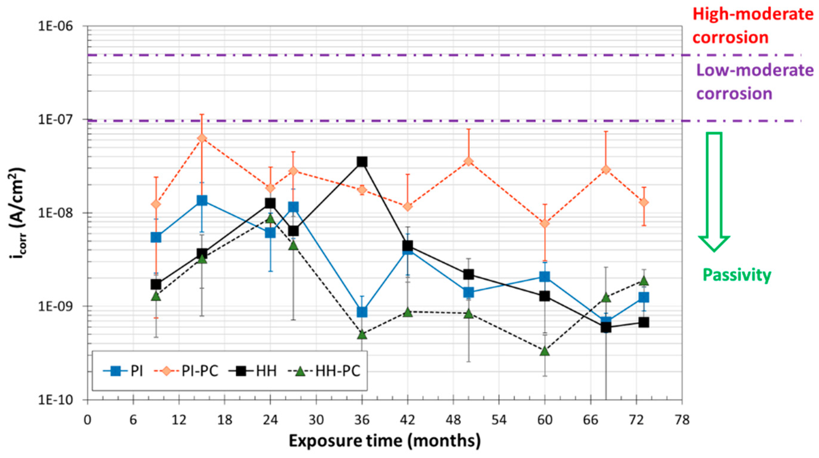
HH: Non-carbonated samples manufactured without chlorides and exposed to high relative humidity (between 90% and 95%).
-
PI: Non-carbonated samples manufactured without chlorides and partially immersed in 3.5% (w/w) NaCl solution and at high relative humidity. In this case, the level of the solution was kept coinciding with the middle of the exposed length of the bars embedded in the mortar.
-
HH-PC: Partially carbonated samples manufactured without chlorides and exposed to high relative humidity (90–95%).
-
PI-PC: Partially carbonated samples manufactured without chlorides, partially immersed in 3.5% (w/w) NaCl solution and at high relative humidity. In this case, the level of the solution was also kept coinciding with the middle of the exposed length of the bars embedded in the mortar.
Three samples reinforced with S32304 bars and three with S32001 bars were exposed to each of the four considered conditions.
Corrosion potential (Ecorr) and electrochemical impedance spectroscopy (EIS) measurements were used to monitor the corrosion behavior of all the samples during the 6-year exposure. A saturated calomel electrode (SCE) was used as reference to obtain the Ecorr. For the EIS measurements, a three-electrode configuration was employed. The surface of corrugated duplex stainless steels exposed to the mortar acted as a working electrode, the reference electrode was a SCE, and the counter-electrode was a copper cylinder with a diameter slightly higher than that of the mortar samples. A wet pad was used to ensure a good contact between the mortar and the counter-electrode. Additional information about the arrangement of the electrodes can be found in [2]. The EIS spectra were acquired using a perturbation signal of 10 mVrms of amplitude, from 104 to 10−3 Hz. Five points per decade were measured. EIS measurements were performed using a potentiostat/galvanostat Solartron Modulab (Ametek Scientific Instruments, Oak Ridge, TN, USA) with Modulab ECS software.
After the 6-year exposure period, the reinforced mortar samples were submitted to anodic polarization tests. The tests started from the Ecorr and potential was increased in steps of 20 mV, with duration of 10 min. When a potential of about 100 mV vs. SCE was reached, the length of the steps increased up to 1 h. The increasing length of the steps was needed due to higher difficulties in stabilizing the current signal after the pulses when the anodic overpotential increases. The polarization steps finished at 700 mV vs. SCE. The current densities plotted in the anodic polarization curves correspond to the stabilization values of the current after each potential step. This strategy was specifically designed to easily discriminate the interferences of the mortar resistivity in the measurements, and to obtain more reliable current values at high anodic overpotentials, where the transitories become more difficult to stabilize. More details about this type of test can be found in [2]. The anodic pulses were performed using the same potentiostat/galvanostat as for EIS measurements.
After the polarization tests, the samples were broken in half and the pH of the studied tested mortars was checked again after exposure using indicators (phenolphthalein and yellow alizarin). Phenolphthalein is commonly used to determine the advance of the carbonation front, but it is sensitive only to very extreme carbonation, and so its use has been questioned [32]. Phenolphthalein is colorless at pH < 8.3 and violet at pH > 10.0. Thus, the mortar becomes colorless with phenolphthalein only when a very large amount of CO2 from the atmosphere has reacted, and the carbonate/bicarbonate buffer (that keeps pH around 10.2) has already been broken. Yellow alizarin is yellow at pH < 10.2 and red at pH > 12.0, so it changes its color at more alkaline pHs than phenolphthalein. In our study, part of the surface of each broken sample was sprayed with phenolphthalein and part with yellow alizarin to check the variation of the alkalinity of the mortar caused by the exposure in the carbonation chamber.
The total chloride content in different regions of the tested samples was measured by X-ray fluorescence spectrometry (XRF) [33]. The measurements were carried out after the 6-year exposure. Specimens coming from three different regions, labeled as 1, 2, and 3 in Figure 1, were evaluated. The equipment used was a SPECTRO XEPOS III X-ray Spectrometer (Spectro, Kleve, Germany) with XLabPro 4.5 Software. The given values for Cl concentration are the average of four measurements in each region of different mortar samples and they are expressed in relation to the mortar weight.
After cleaning the surfaces of the bars, the morphology and localization of the attack on them were studied. The possible preferential corrosion of the phases in duplex stainless-steel bars was analyzed by scanning electron microscopy (SEM, Philips, Eindhoven, Netherlands) using a Philips XL30, under voltages ranging between 15 and 17 kV.

3. Results and Discussion

In Figure 2 and Figure 3, information about the pH and the amount of chlorides determined for the mortar samples at the end of the 6-year corrosion tests is shown, with the aim of facilitating a better understanding of the corrosion results that could be seen immediately afterwards.
Figure 2 shows an example of the results obtained after the use of phenolphthalein (on the left part of the broken mortar) and yellow alizarin (on the right part). The use of both indicators indicates that the mortar samples which were previously exposed inside the carbonation chamber had a pore solution pH similar to that given by the carbonate/bicarbonate buffer (around 10.2) or higher, as the surface wetted with phenolphthalein became violet (i.e., pH > 10) and the surface wetted with yellow alizarine was yellow and slightly reddish (i.e., pH < 12). So, the samples had a reduced alkaline reserve and their pHs can be initially considered as between 10 and 12.
The amount of chlorides determined by XRF can be seen Figure 3. In the samples where the chlorides were added during manufacturing (HH and HH-PC), the chloride distribution was uniform throughout the mortar, as expected. The obtained results also show that there were no meaningful differences among the chloride contents of studied regions (Figure 1) in the PI and PI-PC samples after the 6-year immersion period. Though it is feasible to assume that those differences would exist initially, as the chlorides penetrated from the surface of the lowest half of the mortar to the bulk of the mortar and subsequently diffused to the upper half, the concentrations of this depassivant ion seemed to be equalized at the end of the exposure on all the mortars covering the tested surface of the bars.
The data in Figure 3 also show that the long-term partial immersion exposure increased the chloride contents in the mortar to values higher than those of the HH and HH-PC samples. The PI-PC samples tended to have lower chloride concentration than the PI samples. This has also been observed in previous research, when the chloride concentrations in non-carbonated mortars [2] were compared to those in carbonated mortars [3] after similar long-term natural diffusion studies. The precipitation of some carbonates inside the pores of the mortar due to the reaction of the CO2 of the chamber with the hydroxides of the pore solution should obviously represent a slight blockage for the diffusion of chloride ions [34].
The chloride concentrations determined for the PI and PI-PC samples (Figure 3) were about 3.5% and 3%, respectively when they were related to the weight of cement. Bearing in mind the previous results reported by Gastaldi et al. [24], they imply a clear corrosion risk at room temperature under potentiostatic polarizations at 200 mV for non-aged concrete samples. The chloride concentrations for the HH and HH-PC (about 2% in relation to the weight of cement) would not imply corrosion for lean duplex bars in the conditions of the cited study [24].
The results from the Ecorr measurements carried out during the exposure of mortar samples are summarized in Figure 4 and Figure 5. In these figures, the relationship between Ecorr and corrosion probability proposed in the ASTM C876 standard is included. The standard proposes this criterion for non-coated carbon steel reinforcements, but previous results of our group [2,3,35,36] prove its utility also for monitoring stainless steel reinforcements.
In Figure 4, the average Ecorr values obtained for the S32304 bars in each exposure condition are plotted at different times. The vast majority of the measured Ecorr were clearly in the region with passivity probability over 90%. Only one S32304 bar exposed to PI-PC exhibited twice the Ecorr values in the region of uncertain corrosion activity (between −125 and −275 mV vs. SCE) during the monitoring period. This behavior was detected for the same bar S32304 at 15 and at 48 months of exposure, while the other two S32304 bars exposed in the same condition always kept their Ecorr in the passivity region. The slight dispersion observed among the performances of different but theoretically identical samples is easy to understand, as corrosion is a phenomenon very sensitive to small, difficult-to-control variables related to metal surface and the surrounding medium. This experimental dispersion is especially foreseeable when real corrugated surfaces are considered in a heterogeneous medium such as mortar. The results plotted in Figure 4 suggest that S32304 could stand the four aggressive conditions tested, though there is a small possibility that its performance could be endangered if they were embedded in porous mortars with low alkaline reserve and exposed to high chloride concentrations and/or differential aeration cells (i.e., PI-PC condition).
The results from the Ecorr monitoring of the least-alloyed steel (S32001) are plotted in Figure 5. The samples exposed to HH and HH-PC always showed Ecorr values characteristic of passivity, with very few random values in the region of uncertain corrosion activity. The same occurred for the S32001 samples exposed to PI, though one of the three studied samples had its Ecorr in the region with a corrosion probability >90% after 73 months of exposure. The PI-PC condition again seemed to be the most aggressive, often shifting the sample Ecorr from the passivity to uncertainty region and vice versa. Moreover, one bar of S32001 in PI-PC had its Ecorr in the corrosion probability >90% region after 9 months of exposure, other after 36 months and the third after 68 months, though these low Ecorr values always increased again after a short time in the considered monitoring period. These Ecorr oscillations suggest that if corrosion onset occurs, repassivation will probably take place later.
With the aim of checking the validity of the corrosion trend suggested by the Ecorr and obtaining more information about the real corrosion rate of the samples and their passivation mechanism, a complete EIS study was carried out at the same time during the testing period. Spectra such as those shown in the examples in Figure 6a were obtained during the study. To achieve a proper simulation of this experimental behavior, it was checked that the equivalent circuit plotted in Figure 6b was necessary. This equivalent circuit comprises (in series with the mortar resistance (Rm)) three time constants. The lowest-frequency time constant has often been identified with the charge transfer process taking place on the surface of stainless steel rebars, Rt being the charge transfer resistance and CPEdl the constant phase element used to simulate the non-ideal capacitive behavior of the double layer. The medium-frequencies time constant is identified with the electrical behavior of the passive layer formed on the reinforcements, Rpl and CPEpl being the resistance and the constant phase element used to simulate the resistive and the non-ideal capacitive behaviors of this layer. The identification of the phenomenon taking place at low and medium frequencies is a controversial point in the previous literature, as some studies have identified the charge transfer process with that occurring at medium frequencies [25], while others have identified it with that occurring at high frequencies [12]. The authors consider that if Rpl would be on the order of magnitude of the resistance at low frequency, the ohmic drop at the surface of the passive materials would be huge, and this is not the case.
The high-medium frequencies time constant was identified with the resistance (RL) and capacitive behavior (CPEL) of the layer of Ca-rich hydration products formed on the surface of the bars, whose presence and characteristics have been previously studied [37,38,39]. A circuit similar to that in Figure 6b—but without the high–medium frequencies time constant—has been used in other studies to simulate the electrochemical performance of stainless-steel reinforcements in simulated pore solutions [5,12] and in mortar [2,20]. The length of the study and the high-quality search for the simulation have proved the interest in including this new time constant that has been identified with the layer of hydration products.
All the results obtained from the simulation of the EIS spectra for the different exposure conditions are summarized in Table 3, Table 4, Table 5 and Table 6. The values of parameters related to the mortar (Rm, RL, and CPEL and its associated nL) correspond to the mean values of measurements carried out in samples reinforced with S32001 and S32304. The values corresponding to parameters related to the electrochemical behavior of the stainless steels (Rpl, CPEpl, npl, Rt, CPEdl, and ndl) are shown bearing in mind the nature of the reinforcement. The standard deviations corresponding to the experimental dispersion of the measurements are included in the tables.
After several months of exposure, when the monitoring started, the mortar had already become a quite stable material, and so the Rm hardly changed during the testing period. Any decrease of Rm due to chloride diffusion was masked by the curing of the mortar. The HH-PC mortar (Table 6) shows Rm that tended to increase with time and that became clearly higher than those determined for other conditions (Table 3, Table 4 and Table 5) after 2 years of exposure.
The values related to the layer of hydration products formed on the surface show that, after some time, it was more resistive in PI mortars (Table 3). In PI-PC (Table 4), the partial carbonation seemed to reduce their electrochemical influence in the spectra, the determined RL values being lower than those obtained for PI materials (Table 3). Moreover, when the first measurements were carried out, the nL values obtained for partially immersed samples (PI and PI-PC) were already lower than those obtained for samples exposed at high relative humidity (HH and HH-PC) (Table 5 and Table 6). It is also clear that while nL kept its value relatively constant in HH and HH-PC samples during the exposure, this parameter decreased its value with time in PI and PI-PC samples. This suggests that when the pores are saturated with water and/or the chloride content is very high, the deposits tend to become less homogeneous with time.
On the other hand, the values corresponding to Rpl tended to increase with time when the mortar was not carbonated (PI and HH) (Table 3 and Table 5), and the trend was not clear for passive layers in less alkaline media (PI-PC and HH-PC) (Table 4 and Table 6). The Rpl values obtained for the lean duplex in this study were somewhat lower than those reported for austenitic stainless steels in studies carried out in similar conditions [2,3]. The CPEdl values obtained for PI and PI-PC (Table 3 and Table 4) seemed higher than those obtained for HH and HH-PC (Table 5 and Table 6), which could imply that the fuller the saturation of the pores, or perhaps the higher chloride content of their solution (Figure 3), the thinner—that is, more capacitive—the passive layers.
The most relevant parameter for the corrosion kinetics of the reinforcements is the low-frequency resistance. The Rt values were orders of magnitude higher than the other resistances identified in the spectra (Table 3, Table 4, Table 5 and Table 6), so, the charge transfer process was the controlling rate step, and Rt can be directly related with the polarization resistance, Rp, in the Stern-Geary equation [40] and can be used to calculate the corrosion rate (icorr). If a value for the B constant of 50 mV is assumed (as is usually done for passive steels in concrete and mortar [41]), the icorr of each reinforcement for each time and condition can be easily calculated. The average icorr values obtained for S32304 and S32001 lean duplex reinforcements in the different testing conditions considered can be seen in Figure 7 and Figure 8, respectively.
In Figure 7, it can be seen that S32304 stainless steel always kept its average icorr inside the range of values typical of passive steel [42,43]. The PI-PC condition was confirmed to be the most aggressive one, and one of the three bars tested in this condition, at three different times during the testing period, had icorr approaching or slightly surpassing the 0.1 μA/cm2 limit. These three icorr values correspond to Ecorr in the range of uncertain corrosion activity (Figure 4). It is important to stress that, although some very low-intensity corrosion activity occasionally occurs in S32304 reinforcements when they have been exposed to very high chloride concentration and the mortar pores are water saturated, when this low-intensity attack took place during the testing period, it was always repassivated. The results obtained for S32304 were similar to those obtained for austenitic S30400 in mortars exposed in similar non-carbonated conditions [2], and they agreed with previous results about the corrosion resistance of this lean duplex grade obtained in solution tests [18].
The results regarding the icorr measured for S32001 reinforcements can be seen in Figure 8. The PI-PC condition was confirmed to be especially dangerous for the cheapest grade under study. Meaningful icorr values were occasionally measured for this low-alloyed duplex stainless steel in this condition (after 42 months and at the end of exposure for the three tested rebars, and also after 68 months for two of them). The S32001 steel in PI condition had a single icorr value slightly higher than 0.1 μA/cm2, and this point corresponds to an Ecorr in the range of uncertain corrosion activity, although there were other Ecorr values for S32001 in PI treatment in the range of uncertain corrosion activity whose icorr clearly corresponded to passive reinforcements. Previous results in fully carbonated solutions have already suggested that S32001 grade steel could suffer chloride-induced corrosion in this media [18]. However, the values obtained for S32001 reinforcements in PI suggest that the higher chloride content in the mortar than in the HH-PC could more strongly affect the icorr than the decrease in the alkaline reserve performed in this study before the exposures. Pitting corrosion has already been reported for S32001 when the bars were embedded in extremely porous chloride-contaminated mortar [19].
The anodic polarizations carried out at variable, very low rate in all the samples after the exposure allowed us to obtain the results shown in Figure 9 and Figure 10. Although carried out until high anodic polarizations, these studies were always performed in the region of water stability. None of the samples of both studied lean duplex—when they were previously exposed to HH and HH-PC conditions—seemed to pit during the polarization tests. The increases in the current density at potential about 200 mV vs. SCE have been previously identified in tests carried out in alkaline solutions, with the current corresponding to the oxidation of the Cr2O3 present in the passive layer of the stainless steels into CrO42− [15,21]. The fact that these peaks did not suffer a high shift for the samples that had been initially exposed to CO2 [15] indicates that the decrease caused in the pH of the mortar was small. If these results are complemented with those in Figure 2, it can be concluded that the pH of the pore solution in mortar previously exposed to CO2 was slightly below 12. Hence, the decrease in the alkaline reserve of the mortar is the main effect achieved by the exposure in the carbonation chamber that allows us to explain the differences observed between HH and HH-PC and among samples.
After six years of exposure in HH, HH-PC, and PI treatments, S32304 samples exhibited a very stable passivity (Figure 9). However, after exposures in PI-PC, the samples increased their current density when they were submitted to very small anodic overpotentials, reaching values about 0.3–0.5 μA/cm2. This could be considered a worrisome situation if very-long-term durability is expected, as the values are close to corrosion rates that could be considered high or moderate [43]. Moreover, intense pitting activity was also detected at very high anodic overpotentials (+625 mV vs. SCE in the example in Figure 9), when a partial oxidation and dissolution of the passive layer had already taken place (at about 200 mV vs. SCE). This intense pitting attack appeared at such high anodic polarizations that its probability is very remote in practice.
The polarization studies of the S32001 (Figure 10) confirmed the lower stability of its passivity, as already suggested by the results in Figure 8. After exposure in PI-PC, the bars showed icorr values characteristic of active corrosion at Ecorr, and the current densities increased at a moderate rate under increasing anodic polarizations. An intense pitting activity began under moderately high anodic overpotentials (+285 mV vs. SCE in the curve plotted in the figure). If the S32001 bars were embedded in PI mortar, they only pitted at very high anodic overpotentials (between +460 and +500 mV vs. SCE). The curves corresponding to S32001 embedded in mortars with lower chloride concentrations (HH and HH-PC) suggest that no corrosion-related phenomena occurred during the anodic polarization of the bars. After the polarization tests, the mortar cover of the samples was broken and the bars were cleaned to allow a study of the location and morphology of the pits. Besides some mortar adherences and small surface damages caused by the mechanical cleaning process, only visible pits were found in the bars that showed high anodic currents when they were anodically polarized (S32304 after PI-PC and S32001 after PI-PC and PI). The pits (Figure 11) appeared mainly in the lower part of the immersed area of the bars, suggesting that there is no special danger associated to partial immersion conditions, in contrast to what occurs with carbon steel reinforced samples, where macrocell corrosion cannot be considered negligible [44]. This difference could be related to the different corrosion mechanisms taking place in stainless steels and in carbon steel. Moreover, the location of the pits was not related to ribs or more strained regions of the bars. The fact that the studied bars were manufactured by hot working could influence the pit location, as it has already been proved that the working method (i.e., hot or cold) determines the corrosion behavior of stainless-steel reinforcements [45]. Besides these macroscopic pits, the presence of other microscopic pits cannot be discarded.
The microstructural study of the tested bars allowed us to check that the duplex microstructure of the stainless steels made it so that the attack proceeded by selective corrosion of the phases. In duplex stainless steels, austenite always appeared as a discontinuous phase, surrounded by a continuous phase (ferrite). This type of microstructure can be seen in Figure 12, where the etching previously carried out made it so that the ferrite appeared on a lower plane than the austenite. The images in Figure 12 correspond to damaged regions of the surface. The SEM study revealed non-corroded regions, but also small localized attacks, in addition to the large pits already observed (Figure 11).
As can be seen in Figure 12a, in pits formed in regions of the corrugated surface which were only moderately strained, austenite was dissolved selectively, while ferrite tended to remain uncorroded. The higher tendency of ferrite to dissolve Cr can explain this observation. Ferrite should be more Cr-rich than austenite, and therefore more corrosion resistant.
However, in very hard strained regions of the surface (e.g., corrugations or nerves), the ferrite—which is substantially less ductile than the austenite—accumulated much more strain during the working process. These very high stress concentrations in the ferrite decreased the corrosion resistance of this phase, while the decrease caused in the austenite by the strain was not as high. Hence, the relative corrosion resistance of austenite and ferrite reversed in the most strained regions of the surface of the bars. In the pits formed in very strained regions, the ferrite corroded selectively, while the austenite (partially transformed into strain-induced martensite [46]) remained uncorroded (Figure 12b). The selective dissolution of ferrite has already been reported for high-strength lean duplex bars (i.e., high-strained) when they were tested in simulated pore solutions [18].
The change in the relative corrosion resistance of the phases in duplex stainless steels when submitted to strong deformations has already been observed and deeply discussed when they suffer general corrosion in acid medium [47]. In this study, this was checked for both lean duplex stainless steels tested in mortars with low alkaline reserve (Figure 12b), as well as in mortars that kept their initial alkaline reserve (Figure 12c).
The duplex microstructure seemed to be able to stop the deepening of the attack once it was initiated [21], as the most-corrosion-resistant phase can hinder the rate at which the corrosion progresses through the least-corrosion-resistant phase [47] without meaningful galvanic effects. So, the development of the attack through a selective corrosion mechanism can be considered as not especially dangerous for the durability of the structures.

4. Conclusions

In this work, interesting long-term results were obtained regarding the corrosion performance of corrugated lean duplex stainless-steel bars. Those grades are becoming the most relevant material as reinforcement for concrete structures exposed to marine environments, but the knowledge of their behavior is limited. The most innovative conclusions that can be drawn from the results obtained about the durability of S32304 and S32001 in chloride contaminated mortars are:
  • S32304 steel was confirmed to be more corrosion resistant than S32001 (with lower Cr and Ni contents).
  • The durability of S32001 in environments with very high chloride content can be limited, though other factors as the alkalinity of the cover also have a high impact.
  • In mortars that keep their alkalinity, S32304 does not seem to have any corrosion risks for mortar chloride contents up to 1.8% (w/w).The decrease in the alkaline reserve of the mortars—with only a small decrease in their pH—could affect the corrosion behavior of both studied corrugated lean duplex stainless steels in chloride-rich environments.
  • The duplex structure of the stainless steels makes the corrosion proceed by selective corrosion of the phases. Austenite corrodes preferentially except in the most-strained areas of the corrugated surface, where ferrite dissolves selectively.

Author Contributions

Conceptualization, A.B.; methodology, A.B.; validation, A.B., F.V. and M.T.-C.; formal analysis, A.B., F.V. and M.T.-C.; investigation, A.B., F.V. and M.T.-C.; resources, F.V.; data curation, A.B.; writing—original draft preparation, A.B.; writing—review and editing, A.B., F.V. and M.T.-C.; supervision, A.B.; funding acquisition, A.B. and F.V.

Funding

This work was founded by the Ministerio de Ciencia, Innovación y Universidades of Spain through the project RTI2018-096428-B-I00.

Conflicts of Interest

The authors declare no conflict of interest.

References

  1. Pachón-Montaño, A.; Sánchez-Montero, J.; Andrade, C.; Fullea, J.; Moreno, E.; Matres, V. Threshold concentration of chlorides in concrete for stainless steel reinforcement: Classic austenitic and new duplex stainless steel. Constr. Build. Mater. 2018, 186, 495–502. [Google Scholar] [CrossRef]
  2. Bautista, A.; Paredes, E.C.; Velasco, F.; Alvarez, S.M. Corrugated stainless steels embedded in mortar for 9 years: Corrosion results of non-carbonated, chloride-contaminated samples. Constr. Build. Mater. 2015, 93, 350–359. [Google Scholar] [CrossRef]
  3. Bautista, A.; Alvarez, S.M.; Paredes, E.C.; Velasco, F.; Guzmán, S. Corrugated stainless steels embedded in carbonated mortars with and without chlorides: 9-Year corrosion results. Constr. Build. Mater. 2015, 95, 186–196. [Google Scholar] [CrossRef] [Green Version]
  4. Fajardo, S.; Bastidas, D.M.; Ryan, M.P.; Criado, M.; McPhail, D.S.; Morris, R.J.H.; Bastidas, J.M. Low energy SIMS characterization of passive oxide films formed on a low-nickel stainless steel in alkaline media. Appl. Surf. Sci. 2014, 288, 423–429. [Google Scholar] [CrossRef] [Green Version]
  5. Bautista, A.; Blanco, G.; Velasco, F.; Gutierrez, A.; Soriano, L.; Palomares, F.J.; Takenouti, H. Changes in the passive layer of corrugated austenitic stainless steel of low nickel content due to exposure to simulated pore solutions. Corros. Sci. 2009, 51, 785–792. [Google Scholar] [CrossRef]
  6. Gardner, L.; Ng, K.T. Temperature development in structural stainless steel sections exposed to fire. Fire Saf. J. 2006, 41, 185–203. [Google Scholar] [CrossRef]
  7. Pérez-Quiroz, J.T.; Terán, J.; Herrera, M.J.; Martínez, M.; Genescá, J. Assessment of stainless steel reinforcement for concrete structures rehabilitation. J. Constr. Steel Res. 2008, 64, 1317–1324. [Google Scholar] [CrossRef]
  8. Callaghan, B.G. The performance of a 12% Cr chromium steel in concrete in severe marine environments. Corros. Sci. 1993, 35, 1535–1541. [Google Scholar] [CrossRef]
  9. Sedar, M.; Meral, C.; Kunz, M.; Bjegovic, D.; Wenk, H.-R.; Monteiro, P.J.M. Spatial distribution of crystalline corrosion products formed during corrosion of stainless steel in concrete. Cem. Concr. Res. 2015, 71, 93–105. [Google Scholar] [CrossRef] [Green Version]
  10. Kouril, M.; Novak, P.; Bojko, M. Threshold chloride concentration for stainless steel activation in concrete pore solutions. Cem. Concr. Res. 2010, 40, 431–436. [Google Scholar] [CrossRef]
  11. Itty, P.-A.; Sedar, M.; Meral, C.; Parkinson, D.; MacDowell, A.A.; Bjegovic, D.; Monteiro, P.J.M. In situ 3D monitoring of corrosion on carbon steel and ferritic stainless steel embedded in cement paste. Corros. Sci. 2014, 83, 409–418. [Google Scholar] [CrossRef]
  12. Luo, H.; Su, H.; Dong, C.; Xiao, K.; Li, X. Electrochemical and passivation behavior investigation of ferritic stainless steel in simulated concrete pore media. Data Brief 2015, 5, 171–178. [Google Scholar] [CrossRef] [PubMed] [Green Version]
  13. Bertolini, L.; Pedeferri, P. Laboratory and field experience on the use of stainless steels to improve the durability of reinforced concrete. Corros. Rev. 2002, 20, 129–152. [Google Scholar] [CrossRef]
  14. Bautista, A.; Blanco, G.; Velasco, F. Corrosion behaviour of low-nickel austenitic stainless steels reinforcements: A comparative study in simulated pore solutions. Cem. Concr. Res. 2006, 36, 1922–1930. [Google Scholar] [CrossRef]
  15. Moser, R.; Singh, P.M.; Kahn, L.F.; Kurtis, K.E.; González-Niño, D.; McClelland, Z.B. Crevice corrosion and environmentally assisted cracking of high-strength duplex stainless steels in simulated concrete pore solutions. Constr. Build. Mater. 2019, 203, 366–376. [Google Scholar] [CrossRef]
  16. Fajardo, S.; Bastidas, D.M.; Criado, M.; Bastidas, J.M. Electrochemical study of a new-low nickel stainless teel in carbonated solution in the presence of chlorides. Electrochim. Acta 2014, 129, 160–170. [Google Scholar] [CrossRef]
  17. Freire, L.; Novoa, X.R.; Pena, G.; Vivier, V. On the corrosion mechanism of AISI 204Cu stainless steel in chlorinated alkaline media. Corros. Sci. 2008, 50, 3205–3212. [Google Scholar] [CrossRef]
  18. Moser, R.D.; Singh, P.M.; Kahn, L.F.; Kurtis, K.E. Chloride-induced corrosion resistance of high-strength stainless steels in simulated alkaline and carbonated concrete pore solutions. Corros. Sci. 2012, 57, 241–253. [Google Scholar] [CrossRef]
  19. Sedar, M.; Zulj, L.V.; Bjegovic, D. Long-term corrosion behaviour of stainless reinforcing steel in mortar exposed in chloride environment. Corros. Sci. 2013, 69, 149–157. [Google Scholar] [CrossRef]
  20. Alvarez, S.M.; Bautista, A.; Velasco, F. Corrosion resistance of corrugated lean duplex stainless steel in simulated concrete pore solutions. Corros. Sci. 2011, 53, 1748–1755. [Google Scholar] [CrossRef]
  21. Medina, E.; Medina, J.M.; Cobo, A.; Bastidas, D.M. Evaluation of mechanical and structural behavior of austenitic and duplex stainless steel reinforcements. Constr. Build. Mater. 2015, 78, 1–15. [Google Scholar] [CrossRef]
  22. Briz, E.; Biezma, M.V.; Bastidas, D.M. Stress corrosion cracking of new 2001 lean–duplex stainless steel reinforcements in chloride contained concrete pore solution: An electrochemical study. Constr. Build. Mater. 2018, 192, 1–8. [Google Scholar] [CrossRef]
  23. Bertolini, L.; Gastaldi, M. Corrosion resistance of low-nickel duplex stainless steel rebars. Mater. Corros. 2011, 62, 120–129. [Google Scholar] [CrossRef]
  24. Gastaldi, M.; Bertolini, L. Effect of temperature on the corrosion behavior of new-low nickel stainless steel in concrete. Cem. Concr. Res. 2014, 56, 52–60. [Google Scholar] [CrossRef]
  25. Duarte, R.G.; Castela, A.S.; Neves, R.; Freire, L.; Montemor, M.F. Corrosion behaviour of stainless steel rebars embedded in concrete: An electrochemical impedance spectroscopy study. Electrochim. Acta 2014, 124, 218–224. [Google Scholar] [CrossRef]
  26. Mundra, S.; Criado, M.; Bernal, S.A.; Provis, J.L. Chloride-induced corrosion of steel rebars in simulated pore solutions of alkali-activated concretes. Cem. Concr. Res. 2017, 100, 385–397. [Google Scholar] [CrossRef]
  27. Gonzalez, J.A.; Otero, E.; Feliu, S.; Bautista, A.; Ramírez, E.; Rodríguez, P.; López, W. Some considerations on the effect of chloride ions on the corrosion of steel reinforcements embedded in concrete structures. Mag. Concr. Res. 1998, 50, 189–199. [Google Scholar] [CrossRef]
  28. Paul, S.C.; Panda, B.; Huang, Y.; Garg, A.; Peng, X. An empirical model design for evaluation and estimation of carbonation depth in concrete. Measurement 2018, 124, 205–210. [Google Scholar] [CrossRef]
  29. Angulo-Ramírez, D.E.; Mejía de Gutiérrez, R.; Valencia-Saavedra, W.G.; de Medeiros, M.H.F.; Hoppe-Filho, J. Carbonation of hybrid concrete with high blast furnace slag content and its impact on structural steel corrosion. Mater. Constr. 2019, 69, e182. [Google Scholar] [CrossRef]
  30. Alonso, M.C.; Luna, F.J.; Criado, M. Corrosion behavior of duplex stainless steelreinforcement in ternary binder concrete exposed to natural chloride penetration. Constr. Build. Mater. 2019, 199, 385–395. [Google Scholar] [CrossRef]
  31. RILEM. Draft recommendation for repair strategies for concrete structures damaged by reinforcement corrosion. Mater. Struct. 1994, 27, 415–438. [Google Scholar] [CrossRef]
  32. Czarnecki, L.; Woyciechowski, P. Concrete carbonation as a limited process and its relevance to concrete cover thickness. ACI Mater. J. 2012, 109, 275–282. [Google Scholar]
  33. Dhir, R.K.; Jones, M.R.; Ahmed, H.E.H. Determination of total and soluble chlorides in concrete. Cem. Concr. Res. 1990, 20, 579–590. [Google Scholar] [CrossRef]
  34. Song, H.-K.; Kwon, S.J. Permeability characteristics of carbonated concrete considering capillary pore structure. Cem. Concr. Res. 2007, 37, 909–915. [Google Scholar] [CrossRef]
  35. Bautista, A.; Paredes, E.C.; Alvarez, S.M.; Velasco, F. Welded, sandblasted, stainless steel corrugated bars in non-carbonated and carbonated mortars: A 9-year corrosion study. Corros. Sci. 2016, 103, 363–372. [Google Scholar] [CrossRef]
  36. Paredes, E.C.; Bautista, A.; Velasco, F.; Alvarez, S.M. Welded, pickled stainless steel reinforcements: Corrosion results after 9 years in mortar. Mag. Concr. Res. 2016, 68, 1099–1109. [Google Scholar] [CrossRef]
  37. Page, C.L. Mechanism of corrosion protection in reinforced-concrete marine structures. Nature 1975, 258, 514–515. [Google Scholar] [CrossRef]
  38. Glass, G.K.; Yang, R.; Dickhaus, T.; Buenfeld, N.R. Backscattered electron imaging of the steel-concrete interface. Corros. Sci. 2001, 43, 605–610. [Google Scholar] [CrossRef]
  39. Chen, F.; Chun-Qing, L.; Baji, H.; Baogue, M. Quantification of steel-concrete interface in reinforced concrete using Backscattered Electron imaging technique. Contr. Build. Mater. 2018, 179, 420–429. [Google Scholar] [CrossRef]
  40. Stern, M.; Geary, A. Electrochemical polarization I. A theoretical analysis of the shape of the polarization curves. J. Electrochem. Soc. 1957, 104, 56–58. [Google Scholar] [CrossRef]
  41. Andrade, C.; Gonzalez, J.A. Quantitative measurements of corrosion rate of reinforcing steel embedded in concrete using polarization resistance measurements. Mater. Corros. 1978, 29, 515–519. [Google Scholar] [CrossRef]
  42. Stefanoni, M.; Angst, U.; Elsener, B. Corrosion rate of carbon steel in carbonated concrete—A critical review. Cem. Concr. Res. 2018, 103, 35–48. [Google Scholar] [CrossRef]
  43. Song, H.W.; Saraswathy, V. Corrosion monitoring of reinforced concrete structures—A review. Int. J. Electrochem. Sci. 2007, 2, 1–28. [Google Scholar]
  44. Revert, A.B.; Hornbostel, K.; De Weerdt, K.; Geiker, M.R. Macrocell corrosion in carbonated Portland and Portland-fly ash concrete—Contribution and mechanism. Cem. Concr. Res. 2019, 116, 273–283. [Google Scholar] [CrossRef]
  45. Paredes, E.C.; Bautista, A.; Alvarez, S.M.; Velasco, F. Influence of the forming process of corrugated stainless steels on their corrosion behaviour in simulated pore solutions. Corros. Sci. 2012, 58, 52–61. [Google Scholar] [CrossRef] [Green Version]
  46. Monrrabal, G.; Bautista, A.; Guzman, S.; Gutierrez, C.; Velasco, F. Influence of the cold working induced martensite on the electrochemical behavior of AISI 304 stainless steel surfaces. J. Mater. Res. Technol. 2019, 8, 1135–1346. [Google Scholar] [CrossRef]
  47. Bautista, A.; Alvarez, S.M.; Velasco, F. Selective corrosion of duplex stainless steel bars in acid. Part II: Effect of the surface strain and numerical analysis. Mater. Corros. 2015, 66, 357–365. [Google Scholar] [CrossRef]
Figure 1. Scheme of the reinforcing mortar samples used in the study.
Metals 09 00686 g001
Figure 2. Image of a broken reinforced sample previously exposed to CO2, after the use of phenolphthalein (left) and yellow alizarin (right) indicators to check pH.
Metals 09 00686 g002
Figure 3. Chloride contents determined at the end of the 6-year exposure for reinforced mortar samples tested in different conditions. The numbers on the x-axis correspond to the regions marked in Figure 1.
Metals 09 00686 g003
Figure 4. Corrosion potential (Ecorr) values obtained for S32304 steel tested under different conditions. SCE: saturated calomel electrode.
Metals 09 00686 g004
Figure 5. Ecorr values obtained for S32001 steel tested under different conditions.
Metals 09 00686 g005
Figure 6. (a) Examples of electrochemical impedance spectroscopy (EIS) spectra, corresponding to S32001 steel tested under HH condition at two different times. Dots correspond to experimental data, and lines correspond to fitting. (b) Equivalent circuit used to simulate all the EIS spectra.
Metals 09 00686 g006
Figure 7. Corrosion rate (icorr) values calculated from EIS experiments for S32304 steel under different testing conditions.
Metals 09 00686 g007
Figure 8. Corrosion rate (icorr) values calculated from EIS experiments for S32001 steel under different testing conditions.
Metals 09 00686 g008
Figure 9. Anodic polarization curves obtained for S32304.
Metals 09 00686 g009
Figure 10. Anodic polarization curves obtained for S32001.
Metals 09 00686 g010
Figure 11. Example of visually detectable pits observed on the surface of tested steels.
Metals 09 00686 g011
Figure 12. SEM images of S32001 steel after polarization tests carried out after: (a) PI-PC, (b) PI-PC, and (c) PI exposures. Images (a) and (b) were taken with backscattered electrons, while image (c) was taken with secondary electrons.
Metals 09 00686 g012
Table 1. Mechanical properties of the duplex stainless-steel bars.
UNS GradeUltimate Tensile Strength (MPa)Yield Strength (MPa)Elongation (%)
S3230476956838
S3200182455344
Table 2. Chemical composition (w/w) of the duplex stainless-steel bars.
UNS GradeChemical Composition (%)
CSSiMnCrNiMoNCuFe
S323040.0170.0020.571.6823.74.320.240.1530.186Bal.
S320010.0250.0020.754.3920.61.740.220.1240.073Bal.
Table 3. Results from simulations of the EIS spectra of reinforced samples tested under PI condition.
EIS Simulation ParametersMonths
91524364250606873
Rm
(Ω·cm2)
268
± 36
202
± 70
247
± 146
263
± 112
202
± 79
240
± 86
256
± 92
218
± 108
205
± 73
RL
(Ω·cm2)
112
± 42
65
± 27
225
± 119
527
± 112
482
± 85
802
± 531
838
± 497
1159
± 355
1379
± 286
CPEL
(μF·cm−2·sn−1)
30
± 19
34
± 17
20
± 12
19
± 3
22
± 3
30
± 11
34
± 10
30
± 5
29
± 10
nL0.76
± 0.14
0.78
± 0.12
0.81
±0.11
0.72
± 0.05
0.74
± 0.03
0.75
± 0.08
0.78
± 0.08
0.69
± 0.07
0.69
± 0.03
Rpl
(kΩ·cm2)
S323040.4
± 0.0
0.3
± 0.1
0.5
± 0.2
0.4
± 0.0
0.6
± 0.2
1.3
± 0.6
1.5
± 0.7
1.5
± 0.5
1.6
± 0.4
S320010.4
± 0.1
0.2
± 0.1
0.3
± 0.2
0.7
± 0.1
0.6
± 0.0
1.9
± 1.6
1.8
± 0.9
2.0
± 1.3
3.2
± 0.2
CPEpl
(μF·cm−2·sn−1)
S32304130
± 19
141
± 5
142
± 49
89
± 20
101
± 16
111
± 23
92
± 26
106
± 24
107
± 16
S3200199
± 10
88
± 22
108
± 64
32
± 10
64
± 7
65
± 53
79
± 23
81
± 24
86
± 9
nplS323040.97
± 0.03
0.97
± 0.02
0.96
± 0.00
0.96
± 0.02
0.95
± 0.01
0.96
± 0.01
0.95
± 0.02
0.96
± 0.02
0.96
± 0.02
S320010.99
± 0.01
0.95
± 0.06
0.96
± 0.02
0.89
± 0.01
0.95
± 0.01
0.92
± 0.12
0.97
± 0.03
0.99
± 0.01
0.99
± 0.01
Rt
(MΩ·cm2)
S3230414
± 8
5.2
± 3.1
13
± 8
67
± 24
16
± 7.7
37
± 5
28
± 10
78
± 20
43
± 11
S320015.2
± 1
0.7
± 0.3
5.3
± 2.7
9.7
± 2
8.2
± 7
8.4
± 2.6
16
± 9.5
36
± 27
19
± 8.8
CPEdl
(μF·cm−2·sn−1)
S32304130
± 33
127
± 30
163
± 20
170
± 53
187
± 22
141
± 17
165
± 24
160
± 19
159
± 20
S3200198
± 20
140
± 45
133
± 48
171
± 20
132
± 6
106
± 40
87
± 22
75
± 18
64
± 1
ndlS323040.94
± 0.04
0.93
± 0.02
0.94
± 0.01
0.94
± 0.01
0.94
± 0.01
0.94
± 0.01
0.94
± 0.01
0.94
± 0.02
0.94
± 0.02
S320010.98
± 0.01
0.95
± 0.01
0.95
± 0.02
0.94
± 0.01
0.94
± 0.01
0.94
± 0.03
0.92
± 0.05
0.93
± 0.05
0.97
± 0.03
Table 4. Results from simulations of the EIS spectra of reinforced samples tested under PI-PC condition.
EIS Simulation ParametersMonths
91524364250606873
Rm
(Ω·cm2)
268
± 35
249
± 62
247
± 94
263
± 59
202
± 84
240
± 89
256
± 98
218
± 87
205
± 118
RL
(Ω·cm2)
102
± 16
101
± 69
112
± 71
182
± 92
153
± 67
313
± 74
257
± 111
201
± 172
611
± 290
CPEL
(μF·cm−2·sn−1)
72
± 41
29
± 15
65
± 40
44
± 29
32
± 25
22
± 8
21
± 12
15
± 11
13
± 14
nL0.74
± 0.09
0.86
± 0.16
0.83
± 0.11
0.84
± 0.07
0.80
± 0.09
0.67
± 0.12
0.66
± 0.11
0.75
± 0.10
0.64
± 0.06
Rpl
(kΩ·cm2)
S323040.8
± 0.2
0.8
± 0.5
0.8
± 0.3
0.3
± 0.0
0.4
± 0.1
0.5
± 0.1
0.4
± 0.1
0.4
± 0.2
0.5
± 0.2
S320010.6
± 0.2
0.3
± 0.1
0.9
± 0.6
0.5
± 0.0
0.4
± 0.2
0.4
± 0.3
0.8
± 0.7
0.3
± 0.0
0.9
± 0.8
CPEpl
(μF·cm−2·sn−1)
S32304114
± 18
118
± 85
131
± 23
126
± 22
133
± 19
70
± 21
154
± 80
140
± 66
145
± 75
S3200189
± 9
110
± 27
157
± 89
106
± 13
131
± 29
92
± 31
109
± 72
152
± 29
111
± 83
nplS323040.97
± 0.05
0.97
± 0.04
0.95
± 0.08
0.97
± 0.01
0.96
± 0.00
0.93
± 0.06
0.91
± 0.03
0.92
± 0.04
0.91
± 0.06
S320010.99
± 0.02
0.96
± 0.04
0.93
± 0.06
0.97
± 0.04
0.93
± 0.02
0.96
± 0.04
0.97
± 0.06
0.91
± 0.13
0.94
± 0.09
Rt
(MΩ·cm2)
S323047.3
± 4.1
1.3
± 1.0
3.8
± 2.2
2.9
± 0.3
15
± 7
5
± 2
10
± 6.5
13
± 9
4.7
± 2.5
S320011.1
± 0.7
1.2
± 0.8
17
± 3
0.7
± 0.1
0.1
± 0.1
19
± 10
16
± 10
0.4
± 0.1
0.2
± 0.1
CPEdl
(μF·cm−2·sn−1)
S3230455
± 2
79
± 34
92
± 33
129
± 0
154
± 6
170
± 55
148
± 34
158
± 7
170
± 32
S3200180
± 50
101
± 27
29
± 26
110
± 33
133
± 79
80
± 55
110
± 85
118
± 40
103
± 90
ndlS323040.98
± 0.02
0.93
± 0.07
0.95
± 0.06
0.93
± 0.00
0.93
± 0.00
0.94
± 0.02
0.94
± 0.02
0.93
± 0.01
0.92
± 0.01
S320010.92
± 0.10
0.89
± 0.06
1.00
± 0.00
0.94
± 0.04
0.94
± 0.05
0.94
± 0.06
0.95
± 0.07
0.92
± 0.12
0.95
± 0.04
Table 5. Results from simulations of the EIS spectra of reinforced samples tested under HH condition.
EIS Simulation ParametersMonths
91524364250606873
Rm
(Ω·cm2)
282
± 53
227
± 47
276
± 98
234
± 41
197
± 25
261
± 64
295
± 50
205
± 58
208
± 59
RL
(Ω·cm2)
120
± 31
72
± 40
150
± 25
55
± 39
116
± 96
90
± 63
191
± 95
84
± 57
71
± 21
CPEL
(μF·cm−2·sn−1)
33
± 16
26
± 23
39
± 31
28
± 19
34
± 33
17
± 12
39
± 14
19
± 22
14
± 8
nL0.85
± 0.07
0.86
± 0.05
0.82
± 0.10
0.87
± 0.05
0.88
± 0.12
0.80
± 0.06
0.88
± 0.02
0.83
± 0.08
0.82
± 0.07
Rpl
(kΩ·cm2)
S323041.1
± 0.2
1.0
± 0.1
2.5
± 0.4
2.1
± 1.2
1.8
± 1.3
3.7
± 1.4
7.8
± 1.4
2.9
± 1.8
5.5
± 3.3
S320010.8
± 0.5
0.7
± 0.4
2.6
± 0.6
6.5
± 5.5
0.9
± 0.7
1.8
± 1.5
15.0
± 8.1
2.6
± 2.3
5.6
± 1.0
CPEpl
(μF·cm−2·sn−1)
S3230454
± 10
95
± 18
68
± 20
113
± 5
121
± 8
122
± 9
78
± 46
103
± 24
77
± 8
S3200161
± 18
70
± 18
75
± 0
90
± 35
62
± 48
71
± 13
95
± 11
62
± 26
42
± 19
nplS323040.89
± 0.02
0.93
± 0.01
0.91
± 0.02
0.90
± 0.00
0.94
± 0.03
0.90
± 0.00
0.90
± 0.03
0.89
± 0.02
0.88
± 0.03
S320010.96
± 0.01
0.94
± 0.07
0.91
± 0.12
0.95
± 0.02
0.94
± 0.01
0.91
± 0.05
0.94
± 0.01
0.94
± 0.01
0.96
± 0.05
Rt
(MΩ·cm2)
S3230430
± 8
19
± 13
68
± 3
2
± 0
17
± 10
29
± 15
60
± 43
150
± 77
270
± 179
S3200110
± 2
27
± 20
12
± 4
8
± 5
14
± 6
28
± 7
330
± 140
23
± 6
77
± 35
CPEdl
(μF·cm−2·sn−1)
S32304145
± 10
97
± 24
114
± 25
100
± 17
79
± 32
75
± 17
87
± 28
92
± 48
94
± 25
S3200187
± 20
83
± 8
67
± 25
74
± 64
106
± 31
96
± 16
38
± 18
78
± 29
98
± 9
ndlS323040.89
± 0.03
0.93
± 0.01
0.91
± 0.02
0.90
± 0.00
0.94
± 0.03
0.90
± 0.00
0.90
± 0.03
0.89
± 0.02
0.88
± 0.03
S320010.96
± 0.01
0.94
± 0.07
0.95
± 0.01
0.95
± 0.02
0.94
± 0.01
0.91
± 0.05
0.94
± 0.01
0.94
± 0.01
0.93
± 0.01
Table 6. Results from simulations of the EIS spectra of reinforced samples tested under HH-PC condition.
EIS Simulation ParametersMonths
91524364250606873
Rm
(Ω·cm2)
312
± 57
309
± 70
442
± 35
463
± 54
324
± 37
463
± 101
549
± 57
422
± 73
472
± 53
RL
(Ω·cm2)
127
± 105
125
± 51
324
± 126
308
± 139
186
± 69
241
± 70
346
± 206
250
± 223
271
± 157
CPEL
(μF·cm−2·sn−1)
32
± 30
28
± 11
35
± 15
28
± 8
33
± 15
17
± 8
19
± 8
17
± 7
16
± 9
nL0.87
± 0.07
0.89
± 0.03
0.88
± 0.04
0.86
± 0.05
0.87
± 0.03
0.84
± 0.02
0.85
± 0.05
0.84
± 0.06
0.83
± 0.05
Rpl
(kΩ·cm2)
S323041.1
± 1.0
0.5
± 0.2
1.8
± 0.6
1.8
± 0.8
1.1
± 0.5
1.3
± 0.6
1.6
± 0.4
1.4
± 0.6
2.3
± 1.4
S320010.5
± 0.4
0.5
± 0.2
3.1
± 1.5
1.6
± 1.0
1.5
± 1.4
1.1
± 0.3
0.7
± 0.2
0.6
± 0.1
0.7
± 0.1
CPEpl
(μF·cm−2·sn−1)
S3230484
± 20
80
± 6
81
± 19
81
± 28
96
± 16
80
± 12
79
± 4
86
± 9
88
± 7
S3200167
± 13
67
± 15
85
± 9
68
± 15
83
± 15
48
± 11
63
± 15
69
± 19
60
± 21
nplS323040.94
± 0.00
0.94
± 0.00
0.93
± 0.01
0.92
± 0.01
0.93
± 0.01
0.91
± 0.01
0.92
± 0.01
0.93
± 0.01
0.92
± 0.02
S320010.95
± 0.02
0.95
± 0.01
0.93
± 0.01
0.89
± 0.02
0.92
± 0.02
0.90
± 0.02
0.91
± 0.03
0.89
± 0.02
0.89
± 0.02
Rt
(MΩ·cm2)
S3230450
± 27
32
± 28
20
± 22
130
± 72
200
± 130
80
± 42
190
± 120
82
± 64
28
± 10
S3200123
± 14
23
± 16
69
± 48
140
± 30
77
± 97
24
± 17
180
± 97
40
± 10
170
± 105
CPEdl
(μF·cm−2·sn−1)
S3230477
± 22
101
± 20
84
± 21
96
± 12
82
± 11
97
± 14
91
± 17
86
± 7
78
± 16
S32001112
± 14
105
± 21
69
± 15
75
± 20
79
± 28
75
± 7
85
± 36
81
± 26
86
± 30
ndlS323040.91
± 0.00
0.91
± 0.00
0.91
± 0.01
0.91
± 0.01
0.90
± 0.00
0.90
± 0.00
0.90
± 0.01
0.91
± 0.01
0.90
± 0.00
S320010.94
± 0.00
0.92
± 0.01
0.92
± 0.01
0.87
± 0.02
0.89
± 0.02
0.88
± 0.02
0.91
± 0.03
0.90
± 0.04
0.90
± 0.03

