Article

Three-Dimensional (3D) Microstructure-Based Modeling of a Thermally-Aged Cast Duplex Stainless Steel Based on X-ray Microtomography, Nanoindentation and Micropillar Compression

1
School of Materials Science and Engineering, Tsinghua University, Beijing 100084, China
2
Center for 4D Materials Science, Arizona State University, Tempe, AZ 85287, USA
3
State Key Laboratory of Non-ferrous Metals and Processes, General Research Institute for Nonferrous Metals, Beijing 100088, China
*
Authors to whom correspondence should be addressed.
Metals 2019, 9(6), 688; https://doi.org/10.3390/met9060688
Submission received: 1 May 2019 / Revised: 7 June 2019 / Accepted: 13 June 2019 / Published: 15 June 2019

Abstract

:
Finite element analysis was conducted on a thermally-aged cast duplex stainless steel based on the true three-dimensional (3D) microstructure obtained from X-ray microtomography experiments and using the constitutive behavior of each individual phase extracted from nanoindentation on single-crystal and bicrystal micropillar compression tests. The evolution of the phase morphology, the mechanical properties and the boundary deformation behavior during the aging process are highlighted. Quantitative analysis in terms of the distribution and evolution of the stress and strain in both the as received and aged conditions was performed. The experimental results show that aging at an intermediate temperature has a negligible influence on the morphology of the two phases in cast duplex stainless steel (CDSS). Results from simulations reveal that the mechanical behavior of this material were seriously affected by the microstructure and the mechanical properties of the individual phase and the necking deformation tend to form in the area with less large ferrite grains after aging. In addition, stress localization tends to form at the austenite/ferrite interface, in the narrow region of ferrite grains and in the small ferrite grains.

1. Introduction

Cast duplex stainless steels (CDSS) have been widely used in the nuclear industries due to their outstanding mechanical properties and high corrosion resistance [1,2,3,4], such as primary coolant water pipes for pressurized water reactors (PWR). Such pipes made of CDSS are designed for a 40-year service life under high-temperature (~300 °C) and high-pressure (~15 MPa) conditions [5]. During service, these pipes experience issues of both frequently thermal impact loading and thermal aging embrittlement [6,7,8,9]. In order to get a deeper understanding of the relationship between microstructures and mechanical properties and to get some information that could not be achieved in typical macro tests, many researchers have conducted tensile tests on the micro-scale of duplex steels with both the unaged and aged conditions [5,9,10,11,12,13].
It has been reported that the morphology and the volume fraction of the ferrite phase in duplex steel has an extensive influence on the mechanical performance such as the corrosion resistance [14], the fracture toughness [15,16] and the thermal aging embrittlement [17,18,19,20]. Tavares [14] conducted electrochemical corrosion tests on AISI 317L stainless steel with different microstructures and ferrite contents, which showed that that the microstructural changes affected the pitting corrosion resistance. Li [21] investigated duplex stainless steels equipped with ferrite of different contents through different aging conditions. For the unaged duplex stainless steel, a higher content of ferrite can enhance the mechanical properties, while the impact energies of duplex stainless steel are found to decrease with the increasing ferrite content for the aged condition. Besides the effect of the microstructure, as a multi-phase material, the bulk mechanical properties of CDSS are also highly dependent on the mechanical properties of each individual phase [22,23]. Stewart [22] applied a conventional rule of mixtures approach to the stress–strain data obtained from microconstituents in a dual phase precipitation hardened (DPPH) steel to predict the bulk behavior.
In the early stage, simulation research based on the true microstructure was mainly carried out on a two-dimensional (2D) microstructure [24,25,26], which was easy to obtain. For the simulation with duplex stainless steels, Guo [16] conducted simulation on the 2D microstructure with Z3CN20.09M CDSS under a plane strain loading condition and plane stress loading condition using the flow behavior obtained from the micropillar compression tests. Qin [27] used the representative volume element (RVE) method on a DP600 dual phase steel and predicted the macroscopic multiaxial plasticity behavior of the material from the micro-scale level. Although the numerical simulation based on the true 2D microstructure has been widely used, there are still some disadvantages. One of the important reasons is that the obtained 2D microstructure cannot effectively reflect the material’s microstructure characteristics in 3D, which results in simulation results that sometimes are not consistent with the experimental results. Musienko [28] used a true 3D microstructure and an extended 2D microstructure on the numerical simulations of a polycrystalline copper specimen, and the outcome showed that the simulation results based on a true 3D microstructure are more consistent with the experimental results. Recently, Szlazak [29] conducted the finite element method on a scaffold structure, with the 3D spatial gray value distribution obtained from micro-computed tomography was used to define the mechanical properties of the finite element model.
In comparison with the experiments, a numerical simulation based on the true microstructure can reveal many details that may not be obtained directly through experiments and offer a deep understanding of the relationship between microstructure and mechanical properties. To establish the microstructures-mechanical properties finite element model, the major challenge is to obtain the mechanical properties of each component in the material and the true microstructure of the material accurately. In this work, we aim to introduce a new modeling method that can combine the true 3D microstructure and the mechanical properties of each individual phase of a thermally aged CDSS. The true 3D microstructure was obtained via a lab scale X-ray microtomography approach and the mechanical properties of each individual phase were determined by the nanoindentation and single-crystal micropillar compression tests. More importantly, bicrystal micropillar compression tests were also conducted to investigate the grain boundaries deformation behavior. The distribution and evolution of the stress and strain between different aging conditions are of our great concern.

2. Materials and Methods

The material used in this investigation is a Z3CN20.09M austenitic-ferritic CDSS. Chemical composition tested via the combustion method by an in-situ laser analyzer (LIBSOPA-200, NCS Testing Technology, Beijing, China) is (in wt. %): 20.895 Cr, 8.755 Ni, 0.84 Mn, 1.04 Si, 0.03 C, 0.02 P, 0.004 S, 0.015 Cu, 0.349 Mo and balance Fe. The materials investigated in this study were from a centrifugally cast pipe, which was used in the PWR. The initial cast pipe was solution treated at ~1105 °C for 4.5 h followed by fast water quenching, the inner diameter of the pipe was 27.5 inch and the thickness of the pipe was around 48 cm. The typical 2D microstructure of the solution treated Z3CN20.09M, which was electropolished in a 20 vol. % perchloric acid and 80 vol. % ethyl alcohol solution, is shown in Figure 1. In Figure 1, the ferrite phase shows a complex dendritic morphology with the volume fraction of about 20%.
A lab-source X-ray microtomography system (Zeiss Xradia Versa 520, Carl Zeiss XRM, Pleasanton, CA, USA) was used to evaluate the 3D microstructural evolution during the thermal aging process. The specimen was machined from the outer wall region of the pipe by electrical discharge machining (EDM), then the specimen was mechanically polished to a final cross-sectional area of about 700 × 800 μm2. After mechanical polishing, the as received specimen was scanned first. Then the specimen was aged at 475 °C for 500 h and scanned at the same position. Absorption contrast tomography scans were performed on the specimen with the scan parameter of accelerating voltage 80 kV, exposure time 15 s, 3201 projections and using an 4× objective lens. The source to sample distance was 10 mm and sample to detector distance was 47 mm resulting in a pixel size of 1.2 um. The reconstruction process was made using an equipped software package (Zeiss XMReconstructor, Carl Zeiss XRM, Pleasanton, CA, USA); further data processing was made with ImageJ (NIH Image, Bethesda, MD, USA) and Avizo software (Version 9.0.1, FEI Visualization Sciences Group, Hillsboro, OR, USA). More details of the X-ray microtomography experiments can be found elsewhere [30]. The numerical simulation part was done with the commercial FEM software Abaqus (Abaqus/CAE 2017, Dassault Systèmes, Paris, France) due to its advantage on solving the nonlinear problems with a large deformation. Conversion of the surface mesh made by Avizo into a 3D volume mesh that can be used in Abaqus was completed by using HyperWorks (Version 14.0, Altair Engineering Inc., Troy, MI, USA).
Samples for nanoindentation and micropillar compression were prepared by machining small specimens from the as received material and aged at 475 °C for 2000 h material via the EDM method. Nanoindentation and micropillar compression tests were all performed at room temperature using a commercial nanoindenter (XP, Agilent Technologies, Santa Clara, CA, USA) with different indenter tips (Berkovich tip for nanoindentation and 4-sided pyramidal tip for micropillar compression) using the continuous stiffness measurement (CSM) technique. For the micropillar compression tests, both single-crystal and bicrystal micropillars were machined and imaged using the ZEISS Auriga Crossbeam system (Carl Zeiss Microscopy, München, Germany) with the final aspect ratio (height/diameter) around 3 based on Zhang’s simulation results [31]. The nominal compression strain rate was set to be ~10−3 s−1 and the compression strain target was 20%. Details of the nanoindentation and micropillar compression of this material can be found in our previous study [8]. The diameter of the top surface was used to calculate the stress. The nominal diameter of the top surface for the single-crystal micropillars is 2 μm. For the bicrystal micropillars, the nominal diameter of the top surface is 1.5 μm. The bicrystal micropillars were machined in large grains and fabricated carefully to make sure the austenite/ferrite boundary is in the center of the final pillars.

3. Results and Discussion

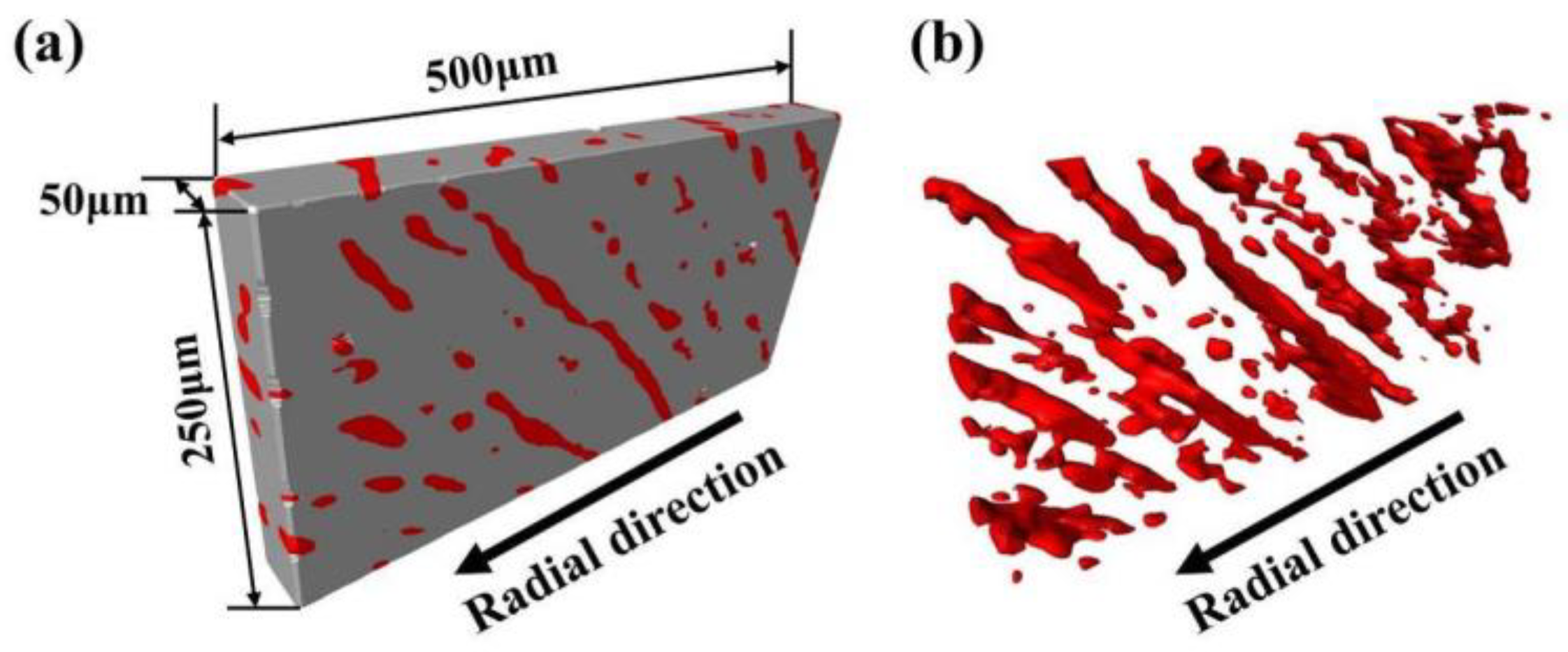
3.1. 3D Microstructural Evolution During Thermal Aging

Figure 2 shows the initial tomography scan results for different aging conditions at the same location. Figure 2a,b was the scan results in the as received condition, while Figure 2c,d was the scan results with the same sample aged at 475 °C for 500 h. Figure 2c,d corresponds to the same locations as that of Figure 2a,b, respectively. From Figure 2, it can be seen that after long-term thermal aging at an intermediate temperature, the morphology of the two phases in Z3CN20.09M CDSS does not change, i.e., a one-to-one correlation can be found. Thus, researchers can combine the constitutive relationships obtained at different aging conditions with the same initial 3D microstructure to simulate the mechanical behavior at different aging conditions, which will be helpful to investigate the effect of thermal aging individually. It is already well established that the evolution on mechanical properties on CDSS among different aging conditions is caused by the spinodal decomposition and the G-phase precipitation [7,8,9,32,33,34].

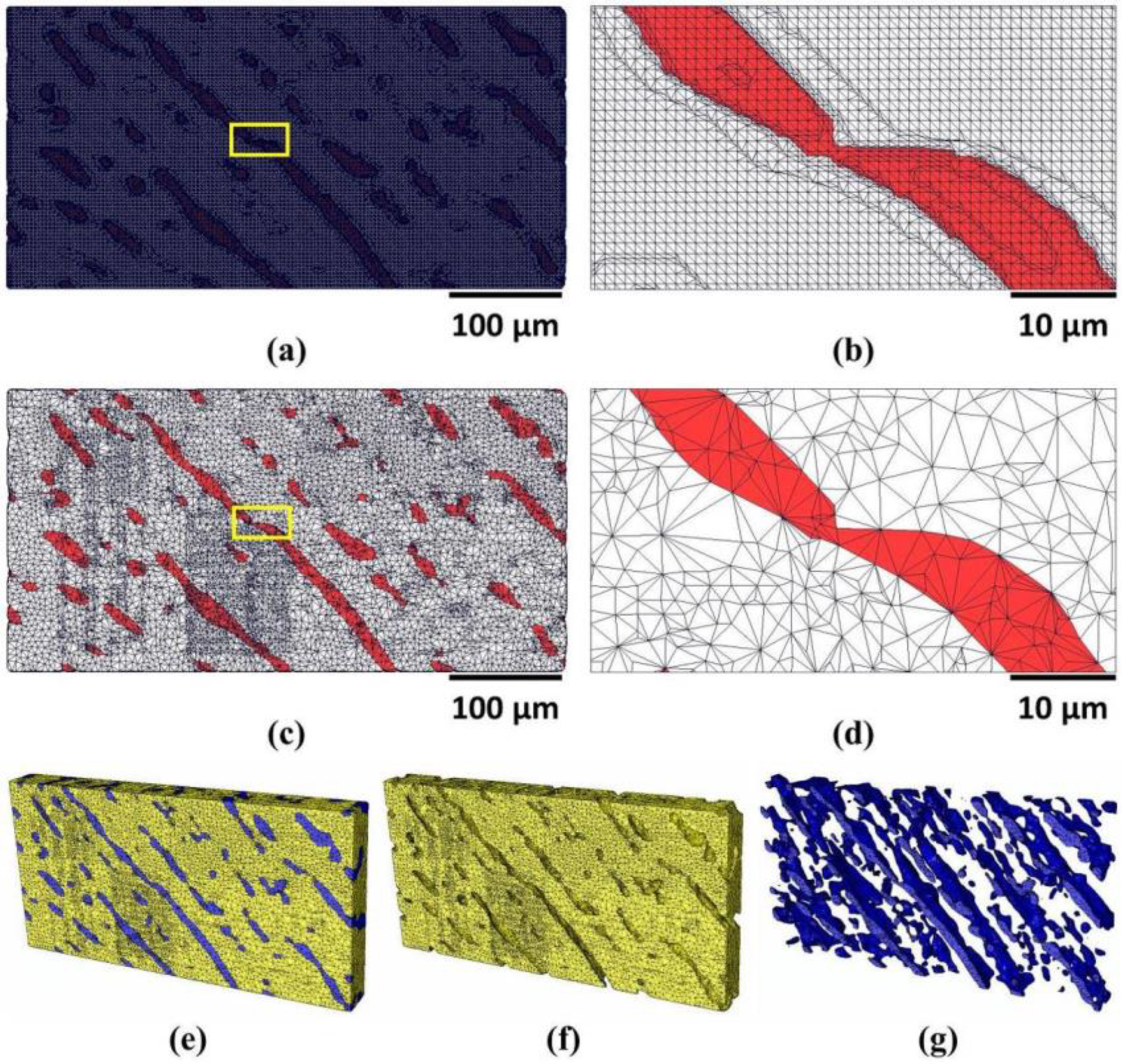
3.2. True Microstructure-Based Modeling

Previous work [30] has proved that after solution treatment, the volume fraction and morphology of ferrite from different locations of the pipe were similar. Thus, a representative area from the outer wall region of the cast pipe, which was reconstructed and discussed in the previous work [30] was selected as the model for the numerical simulation part, shown in Figure 3. The selected area shows a long flat plate shape with the dimension 50 × 250 × 500 μm3, shown in Figure 3a. In Figure 3a, the 500 μm side is parallel to the redial direction of the cast pipe and the volume fraction of the ferrite phase is 16.8%. Figure 3b shows the reconstruction results of the ferrite phase only, it can be noticed that most of the large ferrite grains are parallel to each other.
The selected area in Figure 3 was reconstructed by Avizo. Transferring the Avizo generated file directly into Abaqus is a challenge due to the default settings of surface rendering in Avizo software. Firstly, the rendering results was just a “surface view”, which means only the external surfaces of the two faces were generated and the volume inside them was empty. Then the surface mesh was converted into a 3D volumetric mesh that can be read by Abaqus. Secondly, in order to offer a better surface result, the default size of mesh grids is usually small. Figure 4a,b shows the default mesh grids after surface generation by Avizo. The default grids were simplified first by combining several small grids into one. Figure 4c,d is the simplified surface mesh results. In Figure 4d, the size of the final surface mesh grids is about 2 μm. Then, the finite element pre-processor HyperWorks was used to fill the simplified surface mesh with tetrahedral elements into 3D volume. then the 3D volume was meshed into the tetrahedron elements that can be read by Abaqus. Figure 4e–g shows the 3D volume meshed using HyperWorks. The number of the elements is 216,839 for ferrite phase, 556,611 for austenite phase and 773,450 in total.
In the present work, two types of loading conditions were carried out, shown in Figure 5. In Figure 5a, the loading direcetion was applied to the right face while in Figure 5b the loading direcetion was applied to the top face. Both in Figure 5a and Figure 5b the same overall strain value of 20% was applied. In Figure 5a the left face was confined to have no displacement in the x direction and in Figure 5b the bottom face was confined to have no displacement in the y direction.

3.3. Constitutive Relationships of Austenite and Ferrite from Micropillar Compression

In the present study, constitutive relationships were divided into two parts: The elastic part and the plastic part. For the elastic part, the Young’s modulus of the austenite and ferrite phases with different aging conditions was obtained from the nanoindentation tests, while the micropillar compression results were used for the plastic part. This is because the linear portion of the micropillar compression stress–strain curve contains some degree of compliance and is hard to remove [3], while nanoindentation can get the accurate Young’s modulus results. The Young’s modulus measured from nanoindentation tests is 193 ± 3 GPa for unaged austenite, 232 ± 6 GPa for unaged ferrite, 195 ± 6 GPa for aged austenite and 239 ± 5 GPa for aged ferrite.
The examples of the machined single-crystal micropillars and the corresponding compression stress–strain curves are shown in Figure 6. The surface of the trench around the ferrite pillars is much smoother, which can help us to verify the phase from which the pillar is made from. Figure 6c,f is the compression stress–strain curves for the as received and aged conditions that were used as the input properties for simulation. Here we choose the true stress–strain curves because it can reflect the true mechanical behavior of the material accurately. It should be mentioned that due to single or multiple slip systems activated during micropillar compression process [8], the true strain value might not reach 20%. Thus, based on the default setting of Abaqus, the true stress outside the range of the true strain value obtained from the experiment was assumed constant [35]. From Figure 6c,f, it can be seen that the austenite micropillars show similar stress–strain behavior between the unaged and aged condition while the ferrite micropillars show a significant increase in the compression stress after aging. Hardening in the ferrite phase was caused by the precipitate phases that strengthened the ferrite phase during aging process, such as the spinodal decomposition and the G-phase [8]. The “stair features” in the curves shown in Figure 6c,f indicates that a single or multiple slip system was activated during compression. More discussions of this part can be found elsewhere [8].
The representative fabricated and post-compressed bicrystal micropillars are shown in Figure 7. In Figure 7, all the bicrystal micropillars were machined with boundaries having a random orientation relationship, which would represent the real situation better. From Figure 7a,d, based on the difference in the surface of trench around the pillars, the boundary can be observed clearly, which can aid in making austenite/ferrite interface boundary at the center of the pillar when machining bicrystal pillars. The high magnification images Figure 7b,e also showed the grain boundary is almost parallel to the axis of the pillar. Figure 7c,f shows the bicrystal micropillars post compression stage. It can be seen that even after an applied deformation strain value of almost 20%, the grain boundaries are still bonded well. Thus, in the present finite element model, the two phases were assumed to have perfect bonding during loading.

3.4. Simulation Results

3.4.1. Stress–Strain Behavior

Figure 8 is the simulated engineering stress–strain curves obtained by different loading directions under different heat treatment conditions.
Both in Figure 8a and Figure 8b, it can be concluded that the aged at 475 °C for the 2000 h condition has a higher value in tensile stress than the as received condition. Such phenomenon was also found in the real in-situ tensile experiments of this steel [9]. As the mechanical properties of the austenite phase remain the same after long-term thermal aging [8,34,36], such an increase seen in bulk behavior can be explained by the hardening of ferrite phase during the aging process [8,34]. Former nanoindentation tests have proved that after aging at 475 °C for 2000 h, the nanohardness of ferrite increases by 65% from 3.7 to 6.1 GPa [8]. In Figure 8 the increase in tensile stress also does not seem large, which can be explained by the volume fraction of ferrite in the bulk. In this dual phase steel, the ferrite volume fraction is around 20%, and the mechanical properties of the austenite matrix remains constant after aging. The total tensile stress is controlled by the two phases together. Thus, the total increase of tensile stress is not as large as the ferrite phase itself.
In Figure 8, the simulated stress is higher than the tensile experiments conducted on the same material that was published before [5,9]. This can be explained by two reasons. Firstly, former experiments were conducted at the room temperature and elevated temperatures. The input mechanical properties obtained from the nanoindentation and micropillar compression tests were all conducted at room temperature. It has been reported that working at high temperatures will cause degradation on the mechanical properties [5,9,37,38], so as to reduce the tensile stress. Secondly, many researchers [39,40,41,42,43,44] have reported the phenomenon of “size effect” from micropillar compression tests, i.e., the compression stress of the material increases with the decrease of the diameter of the micropillar. In the present study, the mechanical properties of micropillars with 2 μm diameter were used for the plastic portion of input data. The yield stress of the as received austenite micropillar is about 540 MPa [8], Guo [44] conducted micropillar compression tests on the as received austenite and ferrite micropillars with different diameters from Z3CN20.09M CDSS. They observed the yield stress of austenite micropillar with 2 μm diameter was 510 MPa, which is comparable to ones used in our study. In addition, it was reported that the yield stress of austenite micropillar with 10 μm diameter was 350 MPa, which is a significant decrease in strength to the input value used in this study. Thus, the simulated tensile stress–strain curves have higher value than the experiment results.
Comparing both Figure 8a and Figure 8b, the stress–strain curves with different tensile directions look similar, while in all the conditions, the curves with tensile loading along the y direction have higher tensile stress. For example, at the applied strain of 20%, the tensile stress is ~900 MPa for the unaged condition and ~1100 MPa for the aged condition for the tensile loading along the x direction. This tensile stress increases to ~1000 MPa for the unaged condition and ~1200 MPa for the aged condition for the tensile load applied along the y direction. The only difference between Figure 8a and Figure 8b is the direction along which the tensile load is applied. Thus, the results shown in Figure 8 warrants for an in-depth analysis to understand the effect of microstructure on mechanical properties.

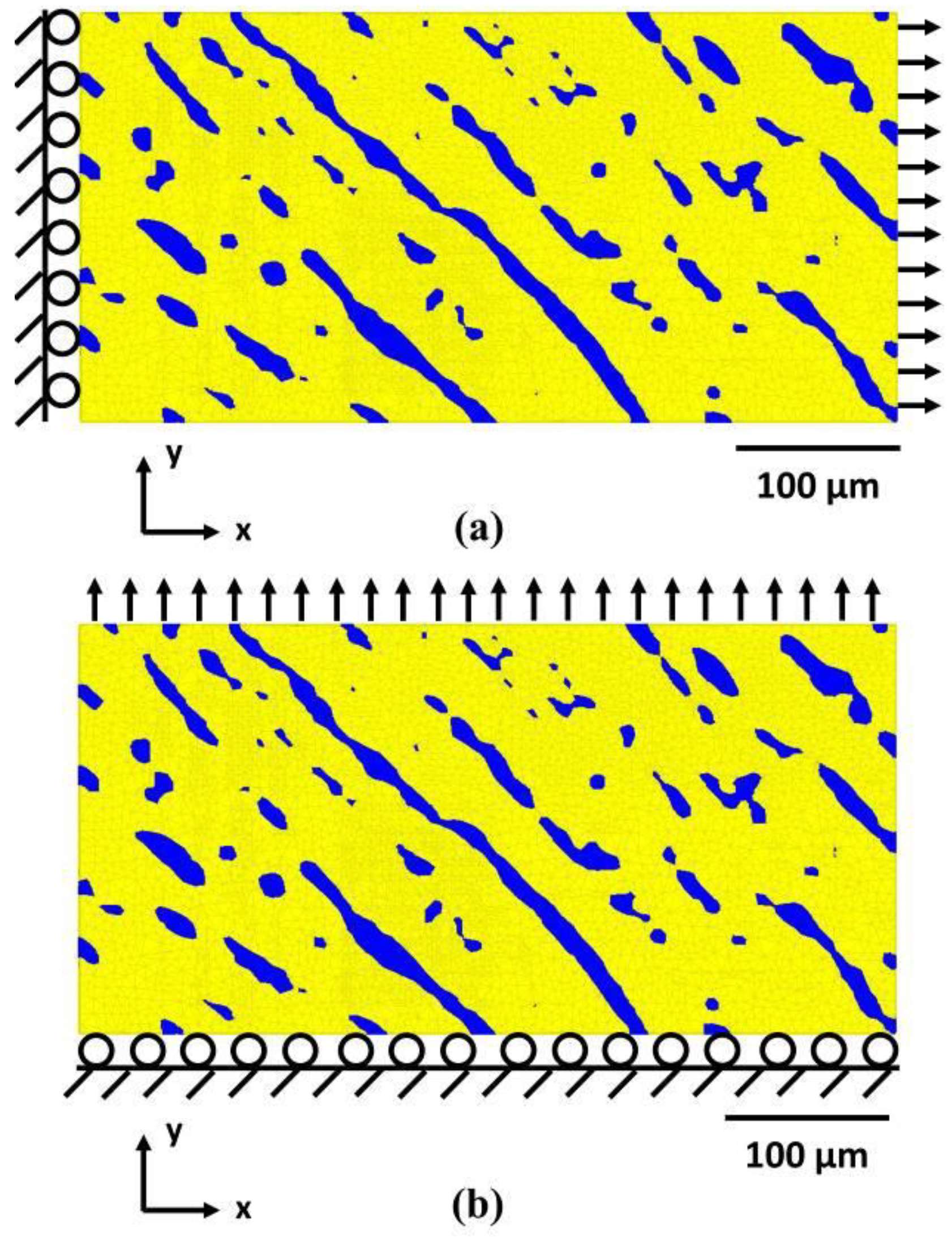
3.4.2. Tensile Deformation

Figure 9 and Figure 10 are the evolution of the equivalent plastic strain and the von Mises stress in the as received and aged at 475 °C for 2000 h condition. In the present study, we are interested in the effect of thermal on mechanical properties and the local deformation behavior. Thus, only the situation with tensile along the x direction was shown. It should be noted that all the color nephograms in Figure 9, Figure 10 and Figure 11 were achieved from Abaqus.
In Figure 9a,e, at a small average strain value, most of the austenite and ferrite phases have a homogeneous local strain and von Mises stress. With the increasing deformation, some local ferrite grains show higher plastic strain while the austenite phase still has a homogeneous local strain, as shown in Figure 9b,c. The plastic part of the micropillar compression stress–strain curves was taken as input and the as received austenite micropillar has a higher stress value than the as received ferrite micropillar in the plastic part shown in Figure 6c. Thus, the ferrite phase may have a higher strain value than the austenite phase under similar stress. Figure 9f shows some stress localization in the austenite phase, which mainly happens along the austenite/ferrite interface. Although the two phases were assumed well bonded, the in situ tensile tests with the same material have proved that the decohesion at the interface may cause the phase separation [5,9]. In Figure 9d, besides the strain localization at the boundary, there is also strain localization in the middle area of the specimen (the black arrow), which can be the region to form the necking deformation.
From Figure 10a–d, the ferrite phase shows a smaller strain value than the austenite phase, which was caused by the significant increase in the hardness of ferrite after long-term thermal aging. In Figure 10c,d, the strain localization forms in the austenite phase (black arrow), and the region of the strain localization shifts a little to the right compared with Figure 9d. The shift may be caused by the difference on the mechanical properties of the two phases and such a shift may cause the shift of necking area. The small circle shown in Figure 10e–h proved the stress localization could be formed in the narrow area of the ferrite grains. A similar phenomenon was also found that the slip lines formed in the austenite matrix first, and then such slip lines can go through some narrow ferrite grains directly without changing the direction [9], which can be explained by the stress localization in these narrow regions. An interesting phenomenon was found here that the small ferrite grains shown in the large circle in Figure 10f–h have higher stress value than the other large ferrite grains. The role of the ferrite grains in the Z3CN20.09M is to hold the austenite matrix because of its dendritic morphology [9], so during tensile deformation, these small ferrite grains can be easily affected by the adjacent austenite and cause local stress concentration inside. While the large ferrite grains can sustain a large deformation and the whole grain can undertake the deformation together to avoid local stress concentration.

3.4.3. Necking Deformation

Figure 11 is the simulated distribution of von Mises stress at the overall strain value 20% for different aging conditions and different tensile directions. In Figure 11 the necking deformation at 20% can be observed clearly. Compared with Figure 11a and Figure 11c, the effect of aging and microstructure on the necking deformation can be observed. After aging, the simulated necking area shift right compared with the as received condition. Former experiments have proven that the fracture of Z3CN20.09M CDSS is mainly caused by the failure of the austenite phase and the role of the ferrite phase is to hold the austenite matrix [9]. In Figure 11a, as the hardness of austenite and ferrite phases are similar (as shown in Figure 6c), the necking forms in the middle of the specimen. The role of the ferrite phase is to hold the austenite matrix, after the aging process the hardness of ferrite phase increases significantly, so in Figure 11c, the necking area shifts right because in the center of the specimen there has large ferrite grains that can sustain a large deformation especially after the aging process. Thus, it can be concluded that after the aging process, as the ferrite grains can hold the austenite matrix better, the necking deformation tends to form in the area with less large ferrite grains. In Figure 11b, the necking also forms in the center area due to the similar hardness of austenite and the ferrite phase in the unaged condition. For Figure 11d, as the large ferrite grain traverses the whole specimen, the necking deformation also formed in the center, where less large ferrite grains exist.

4. Conclusions

In the present study, the numerical simulation method based on the true 3D microstructure under different thermal aging conditions was investigated. From this study, the following can be concluded:
1)
Aging at an intermediate temperature does not change the morphology of the two phases in Z3CN20.09M CDSS and the evolution on mechanical properties on CDSS among different aging conditions was caused by the precipitate phases formed during the aging process that strengthened the ferrite phase, such as the spinodal decomposition and the G-phase.
2)
The compression of bicrystal micropillars with boundaries having a random orientation relationship shows that at the strain value of almost 20% the grain boundaries are still bonded well.
3)
Finite element analysis based on the real 3D microstructure obtained for the X-ray microtomography and the mechanical properties of each individual phase achieved from the nanoindentation and micropillar compression tests is an appropriate numerical simulation method for CDSS, which can reveal some fascinating phenomena that cannot be directly observed by experiments.
4)
The simulated stress–strain curve shows that the aged specimen has a higher tensile stress, which is caused by the hardening of ferrite during the aging process. While the increase rate is not as big as the ferrite phase itself, which can be explained by the ~20% volume fraction of ferrite.
5)
The mechanical behaviors of this material are seriously affected by the mechanical properties of the individual phase. After the aging processes, the necking deformation tends to form in the area with the less large ferrite grains. The stress localization can form at the austenite/ferrite interface, the narrow region of ferrite grains and the small ferrite grains.

Author Contributions

Conceptualization, Q.Z., T.J. and N.C.; Data curation, Q.Z., A.S.S.S. and W.S.; Formal analysis, Q.Z.; Funding acquisition, T.J. and N.C.; Investigation, Q.Z., K.Z., A.S.S.S. and W.S.; Methodology, Q.Z.; Project administration, T.J.; Resources, Q.Z., T.J. and N.C.; Software, Q.Z., K.Z. and A.S.S.S.; Supervision, T.J. and N.C.; Validation, Q.Z., W.S., T.J. and N.C.; Visualization, Q.Z., K.Z. and A.S.S.S.; Writing—original draft, Q.Z.; Writing—review & editing, K.Z., A.S.S.S., T.J. and N.C.

Funding

This research received no external funding.

Acknowledgments

The authors acknowledge use of facilities at the Center for 4D Materials Science at Arizona State University (ASU). Qingdong Zhang is also grateful to the China Scholarship Council for financial support during his stay at Arizona State University. The authors are thankful to Guowei Du from Tsinghua University for the helpful discussions on numerical simulation and to Sridhar Niverty from Arizona State University for assistance with X-ray tomography.

Conflicts of Interest

The authors declare no conflict of interest.

References

  1. Park, Y.; Lee, Z. The effect of nitrogen and heat treatment on the microstructure and tensile properties of 25Cr–7Ni–1.5Mo–3W–xN duplex stainless steel castings. Mater. Sci. Eng. A 2001, 297, 78–84. [Google Scholar] [CrossRef]
  2. Pohl, M.; Storz, O.; Glogowski, T. Effect of intermetallic precipitations on the properties of duplex stainless steel. Mater. Charact. 2007, 58, 65–71. [Google Scholar] [CrossRef]
  3. Guo, E.; Singh, S.S.; Xie, H.; Williams, J.J.; Jing, T.; Chawla, N. Microstructure-Based Modeling of Deformation in Steels Based on Constitutive Relationships from Micropillar Compression. Steel Res. Int. 2014, 85, 946–953. [Google Scholar] [CrossRef]
  4. Li, S.L.; Wang, Y.L.; Wang, X.T. Effects of long term thermal aging on high temperature tensile deformation behaviours of duplex stainless steels. Mater. High Temp. 2015, 32, 524–529. [Google Scholar] [CrossRef]
  5. Guo, E.; Wang, M.; Jing, T.; Chawla, N. Temperature-dependent mechanical properties of an austenitic–ferritic stainless steel studied by in situ tensile loading in a scanning electron microscope (SEM). Mater. Sci. Eng. A 2013, 580, 159–168. [Google Scholar] [CrossRef]
  6. Weng, K.L.; Chen, H.R.; Yang, J.R. The low-temperature aging embrittlement in a 2205 duplex stainless steel. Mater. Sci. Eng. A 2004, 379, 119–132. [Google Scholar] [CrossRef]
  7. Yamada, T.; Okano, S.; Kuwano, H. Mechanical property and microstructural change by thermal aging of SCS14A cast duplex stainless steel. J. Nucl. Mater. 2006, 350, 47–55. [Google Scholar] [CrossRef]
  8. Zhang, Q.; Singaravelu, A.S.S.; Zhao, Y.; Jing, T.; Chawla, N. Mechanical properties of a thermally-aged cast duplex stainless steel by nanoindentation and micropillar compression. Mater. Sci. Eng. A 2019, 743, 520–528. [Google Scholar] [CrossRef]
  9. Zhang, Q.; Ma, S.; Jing, T. Mechanical Properties of a Thermally-aged Cast Duplex Stainless Steel by in Situ Tensile Test at the Service Temperature. Metals 2019, 9, 317. [Google Scholar] [CrossRef]
  10. Serre, I.; Salazar, D.; Vogt, J.B. Atomic force microscopy investigation of surface relief in individual phases of deformed duplex stainless steel. Mater. Sci. Eng. A 2008, 492, 428–433. [Google Scholar] [CrossRef]
  11. Avramovic-Cingara, G.; Ososkov, Y.; Jain, M.K.; Wilkinson, D.S. Effect of martensite distribution on damage behaviour in DP600 dual phase steels. Mater. Sci. Eng. A 2009, 516, 7–16. [Google Scholar] [CrossRef]
  12. Wang, Y.; Yao, Y.H.; Wang, Z.P.; Jin, Y.H.; Zhang, X.L.; Liu, J.N. Thermal ageing on the deformation and fracture mechanisms of a duplex stainless steel by quasi in-situ tensile test under OM and SEM. Mater. Sci. Eng. A 2016, 666, 184–190. [Google Scholar] [CrossRef]
  13. Li, S.; Wang, Y.; Wang, X. In Situ Observation of the Deformation and Fracture Behaviors of Long-Term Thermally Aged Cast Duplex Stainless Steels. Metals 2019, 9, 258. [Google Scholar] [CrossRef]
  14. Tavares, S.S.M.; Feijó, G.F.; Farneze, H.N.; Sandim, M.J.R.; Souza Filho, I.R.D. Influence of Microstructure on the Corrosion Resistance of AISI 317L (UNS S31703). Mater. Res. 2017, 20, 108–114. [Google Scholar] [CrossRef] [Green Version]
  15. Kamiya, O.; Kumagai, K.; Kikuchi, Y. Effects of delta ferrite morphology on low-temperature fracture toughness of austenitic stainless steel weld metal. Weld. Int. 1992, 6, 606–611. [Google Scholar] [CrossRef]
  16. Chen, T.H.; Weng, K.L.; Yang, J.R. The effect of high-temperature exposure on the microstructural stability and toughness property in a 2205 duplex stainless steel. Mater. Sci. Eng. A 2002, 338, 259–270. [Google Scholar] [CrossRef]
  17. Shiao, J.J.; Tsai, C.H.; Kai, J.J.; Huang, J.H. Aging embrittlement and lattice image analysis in a Fe-Cr-Ni duplex stainless steel aged at 400 °C. J. Nucl. Mater. 1994, 217, 269–278. [Google Scholar] [CrossRef]
  18. Timofeev, B.T.; Nikolaev, Y.K. About the prediction and assessment of thermal embrittlement of Cr–Ni austenitic–ferritic weld metal and castings at the ageing temperatures 260–425 °C. Int. J. Press. Vessel Pip. 1999, 76, 849–856. [Google Scholar] [CrossRef]
  19. Chéhab, B.; Bréchet, Y.; Véron, M.; Jacques, P.J.; Parry, G.; Mithieux, J.D.; Glez, J.C.; Pardoen, T. Micromechanics of high-temperature damage in dual-phase stainless steel. Acta Mater. 2010, 58, 626–637. [Google Scholar] [CrossRef]
  20. Li, S.; Wang, Y.; Zhang, H.; Li, S.; Wang, G.; Wang, X. Effects of prior solution treatment on thermal aging behavior of duplex stainless steels. J. Nucl. Mater. 2013, 441, 337–342. [Google Scholar] [CrossRef]
  21. Li, S.; Wang, Y.; Wang, X. Effects of ferrite content on the mechanical properties of thermal aged duplex stainless steels. Mater. Sci. Eng. A 2015, 625, 186–193. [Google Scholar] [CrossRef]
  22. Stewart, J.L.; Jiang, L.; Williams, J.J.; Chawla, N. Prediction of bulk tensile behavior of dual phase stainless steels using constituent behavior from micropillar compression experiments. Mater. Sci. Eng. A 2012, 534, 220–227. [Google Scholar] [CrossRef]
  23. Stewart, J.L.; Williams, J.J.; Chawla, N. Influence of Thermal Aging on the Microstructure and Mechanical Behavior of Dual-Phase, Precipitation-Hardened, Powder Metallurgy Stainless Steels. Metall. Mater. Trans. A 2012, 43, 124–135. [Google Scholar] [CrossRef]
  24. Chawla, N.; Deng, X. Microstructure and mechanical behavior of porous sintered steels. Mater. Sci. Eng. A 2005, 390, 98–112. [Google Scholar] [CrossRef]
  25. Prabu, S.B.; Karunamoorthy, L.; Kathiresan, S.; Mohan, B. Influence of stirring speed and stirring time on distribution of particles in cast metal matrix composite. J. Mater. Process. Technol. 2006, 171, 268–273. [Google Scholar] [CrossRef]
  26. Balasivanandha Prabu, S.; Karunamoorthy, L. Microstructure-based finite element analysis of failure prediction in particle-reinforced metal–matrix composite. J. Mater. Process. Technol. 2008, 207, 53–62. [Google Scholar] [CrossRef]
  27. Qin, S.; McLendon, R.; Oancea, V.; Beese, A.M. Micromechanics of multiaxial plasticity of DP600: Experiments and microstructural deformation modeling. Mater. Sci. Eng. A 2018, 721, 168–178. [Google Scholar] [CrossRef]
  28. Musienko, A.; Tatschl, A.; Schmidegg, K.; Kolednik, O.; Pippan, R.; Cailletaud, G. Three-dimensional finite element simulation of a polycrystalline copper specimen. Acta Mater. 2007, 55, 4121–4136. [Google Scholar] [CrossRef]
  29. Szlazak, K.; Vass, V.; Hasslinger, P.; Jaroszewicz, J.; Dejaco, A.; Idaszek, J.; Scheiner, S.; Hellmich, C.; Swieszkowski, W. X-ray physics-based CT-to-composition conversion applied to a tissue engineering scaffold, enabling multiscale simulation of its elastic behavior. Mater. Sci. Eng. C 2019, 95, 389–396. [Google Scholar] [CrossRef]
  30. Zhang, Q.; Niverty, S.; Singaravelu, A.S.S.; Williams, J.J.; Guo, E.; Jing, T.; Chawla, N. Microstructure and micropore formation in a centrifugally-cast duplex stainless steel via X-ray microtomography. Mater. Charact. 2019, 148, 52–62. [Google Scholar] [CrossRef]
  31. Zhang, H.; Schuster, B.E.; Wei, Q.; Ramesh, K.T. The design of accurate micro-compression experiments. Scr. Mater. 2006, 54, 181–186. [Google Scholar] [CrossRef]
  32. Danoix, F.; Auger, P. Atom Probe Studies of the Fe–Cr System and Stainless Steels Aged at Intermediate Temperature: A Review. Mater. Charact. 2000, 44, 177–201. [Google Scholar] [CrossRef]
  33. Li, S.L.; Wang, Y.L.; Zhang, H.L.; Li, S.X.; Zheng, K.; Xue, F.; Wang, X.T. Microstructure evolution and impact fracture behaviors of Z3CN20-09M stainless steels after long-term thermal aging. J. Nucl. Mater. 2013, 433, 41–49. [Google Scholar] [CrossRef]
  34. Li, S.L.; Zhang, H.L.; Wang, Y.L.; Li, S.X.; Zheng, K.; Xue, F.; Wang, X.T. Annealing induced recovery of long-term thermal aging embrittlement in a duplex stainless steel. Mater. Sci. Eng. A 2013, 564, 85–91. [Google Scholar] [CrossRef]
  35. Abaqus Analysis User’s Guide. Available online: http://dsk.ippt.pan.pl/docs/abaqus/v6.13/books/usb/default.htm (accessed on 20 April 2019).
  36. Liu, G.; Wang, Y.; Li, S.; Du, K.; Wang, X. Deformation behavior of thermal aged duplex stainless steels studied by nanoindentation, EBSD and TEM. Mater. High Temp. 2016, 33, 15–23. [Google Scholar] [CrossRef]
  37. Byun, T.S.; Hashimoto, N.; Farrell, K. Temperature dependence of strain hardening and plastic instability behaviors in austenitic stainless steels. Acta Mater. 2004, 52, 3889–3899. [Google Scholar] [CrossRef]
  38. Choudhary, B.K.; Samuel, E.I.; Sainath, G.; Christopher, J.; Mathew, M.D. Influence of Temperature and Strain Rate on Tensile Deformation and Fracture Behavior of P92 Ferritic Steel. Metall. Mater. Trans. A 2013, 44, 4979–4992. [Google Scholar] [CrossRef]
  39. Uchic, M.D.; Dimiduk, D.M. A methodology to investigate size scale effects in crystalline plasticity using uniaxial compression testing. Mater. Sci. Eng. A 2005, 400–401, 268–278. [Google Scholar] [CrossRef]
  40. Han, S.M.; Bozorg-Grayeli, T.; Groves, J.R.; Nix, W.D. Size effects on strength and plasticity of vanadium nanopillars. Scr. Mater. 2010, 63, 1153–1156. [Google Scholar] [CrossRef]
  41. Huang, L.; Li, Q.; Shan, Z.; Li, J.; Sun, J.; Ma, E. A new regime for mechanical annealing and strong sample-size strengthening in body centred cubic molybdenum. Nat. Commun. 2011, 2, 547. [Google Scholar] [CrossRef] [Green Version]
  42. Kaufmann, D.; Mönig, R.; Volkert, C.A.; Kraft, O. Size dependent mechanical behaviour of tantalum. Int. J. Plast. 2011, 27, 470–478. [Google Scholar] [CrossRef]
  43. Kim, J.; Jang, D.; Greer, J.R. Crystallographic orientation and size dependence of tension–compression asymmetry in molybdenum nano-pillars. Int. J. Plast. 2012, 28, 46–52. [Google Scholar] [CrossRef]
  44. Guo, E.; Xie, H.; Singh, S.S.; Kirubanandham, A.; Jing, T.; Chawla, N. Mechanical characterization of microconstituents in a cast duplex stainless steel by micropillar compression. Mater. Sci. Eng. A 2014, 598, 98–105. [Google Scholar] [CrossRef]
Figure 1. 2D microstructure of the solution treated Z3CN20.09M cast duplex stainless steel.
Metals 09 00688 g001
Figure 2. Results of the initial tomography scans with different aging conditions. (a) and (b) were the scan results of the as received condition. (c) and (d) were the corresponding scan results of (a) and (b), respectively. The sample in (c) and (d) was the same sample as that of (a) and (b) but aged at 475 °C for 500 h.
Metals 09 00688 g002
Figure 3. True 3D microstructure used for numerical simulation. (a) Surface rendering made using Avizo® from the outer wall region of the cast pipe with the austenite matrix (in grey) and ferrite phase (in red); the dimension is 50 × 250 × 500 μm3. (b) Surface rendering of the ferrite phase only.
Metals 09 00688 g003
Figure 4. The meshing process. (a) Default surface mesh result of the selected area, (b) detailed surface mesh result of the highlighted region in (a). (c) The simplified surface mesh result of the selected area and (d) detailed surface mesh result of the highlighted region in (c). (e) 3D mesh with tetrahedron elements of the two phases, (f) only the austenite phase and (g) only the ferrite phase in the selected area.
Metals 09 00688 g004
Figure 5. Two types of loading conditions studied in this work. (a) Tensile along the x direction and (b) tensile along the y direction.
Metals 09 00688 g005
Figure 6. Representative morphology of the fabricated single-crystal micropillars and the corresponding compression results with different aging conditions. (a) The austenite, (b) ferrite micropillars and (c) the micropillar compression results in the as-received condition. (d) The austenite, (e) ferrite micropillars and (f) the micropillar compression results after the aging treatment at 475 °C for the 2000 h condition. The images were taken at a specimen tilt angle of 30°.
Metals 09 00688 g006
Figure 7. Overview SEM Image showing the bicrystalline micropillars for (a) as received condition and (d) aged at 475 °C for the 2000 h condition. (b) and (e) are the high magnification image of (a) and (d), respectively. (c) and (f) are the post-compression images of pillars of (a) and (d), respectively. The images were taken at a specimen tilt angle of 30°; the relevant grain boundaries are highlighted. γ denotes austenite phase, and δ is the ferrite phase.
Metals 09 00688 g007
Figure 8. Simulated stress–strain curves of Z3CN20-09M CDSS by different loading directions under different heat treatment conditions. (a) Tensile along the x direction and (b) tensile along the y direction.
Metals 09 00688 g008
Figure 9. (ad) Evolution of equivalent plastic strain and (eh) the corresponding von Mises stress of (ad) in the as received condition with tensile along the x direction. The overall strain values are (a) and (e) 4.9%, (b) and (f) 6.5%, (c) and (g) 9.3% and (d) and (h) 10.7%.
Metals 09 00688 g009
Figure 10. (ad) Evolution of the equivalent plastic strain and (eh) the corresponding von Mises stress of (ad) in the aged at 475 °C for the 2000 h condition with tensile along the x direction. The overall strain values are (a) and (e) 4.8%, (b) and (f) 6.3%, (c) and (g) 9.5% and (d) and (h) 10.8%.
Metals 09 00688 g010
Figure 11. The von Mises stress at the overall strain value 20% for (a) the as received condition with tensile along the x direction, (b) the as received condition with tensile along the y direction; (c) aged at 475 °C for the 2000 h condition with tensile along the x direction and (d) aged at 475 °C for the 2000 h condition with tensile along the y direction.
Metals 09 00688 g011

