Mathematical Modelling of the Initial Mold Filling with Utilization of an Angled Runner


Department of Material Science and Engineering, KTH Royal Institute of Technology, Brinellvägen 23, SE-100 44 Stockholm, Sweden
*
Author to whom correspondence should be addressed.
Metals 2019, 9(6), 693; https://doi.org/10.3390/met9060693
Submission received: 20 May 2019
/
Revised: 7 June 2019
/
Accepted: 15 June 2019
/
Published: 19 June 2019
Abstract
:The flow pattern plays a crucial role in the uphill teeming process. The non-metallic inclusion generation due to interaction with the mold flux is believed to be influenced by the flow pattern. In this study, a three-dimensional mathematical model of the filling of a gating system for 10, 20, and 30 degrees angled runners was used to predict the fluid flow characteristics. Moreover, a mathematical model with a horizontal runner was applied as a reference. The predictions indicate that the angled-runner-design decreases the hump height during the initial filling stage, which results in less entrapment of mold flux into the mold. Nevertheless, increasing the angle of runner can result in a lower hump height, while the 30 degree angled runner gives a much more stable increase of the hump height during the initial filling stage. Besides CFD calculations, some thermodynamic calculations are taken into account for the chemical reactions between liquid steel and gas. The results show that the bubble shrinks due to the fact that N and O are dissolved into steel. The present findings strongly suggest that changing the horizontal runner to an angled runner would be an effective means of reducing flow unevenness during the initial filling of ingots, if the added steel losses are deemed acceptable.
1. Introduction
In 2016, the ingot production in the world was 3.5% of the total crude steel production, which corresponds to 59 million metric tons [1]. However, ingot casting still plays an important role in some low-alloy steel grades and steels for special applications. Specific examples are high-carbon chromium-bearing steels, thick plates, seamless tubes, forgings, bars, and wire rods [2]. Furthermore, the ingot casting is more suited for making final steel products with huge sizes up to several hundreds of tons. When it comes to the pouring method, the uphill teeming process is preferred over the top pouring process. This is because the molten stream is more exposed to air, suffering from re-oxidation problems for the top pouring method. However, the molten steel flows from trumpet and runner and then enters into the mold, reducing the exposure to air, the entrapment of mold powder, and occurrence of splashing. Thus, uphill teeming method produces a cleaner steel with better internal and surface qualities compared to the uphill teeming method [3].
Figure 1 is a schematic of the uphill teeming process. The process of uphill teeming casting process will briefly be described. First, the liquid steel is poured from the ladle into the refractory lined trumpet. Then the molten steel reaches the center stone at a maximum free fall velocity. This center stone is located in the joint area, where the trumpet is connected to the runners. Thereafter, the molten steel splashes into the runner system due to the collision with the center stone. When in contact with the center stone, it will form a stagnation zone with a very thin boundary layer. The flow filed towards the downstream of impinging jet are divided into laminar boundary layer region, the viscous similarity region, the region of developing turbulence, and the region of fully turbulent flow [4]. Where the stagnation zone boundary layer has little resistance to the heat flow and the convective heat transfer coefficient can reach tens of kW/m2·K [5]. Previous research found that the convective heat transfer coefficients for liquid metal jets are typically three to eight times greater than those for the water jets of same size and speed [6]. Thus, the center stone will be heated very fast. Thereafter, the molten steel is transported from the runner into the mold. Typically, 1.2 kg/t of mold powder in bags are added at the middle of the mold near the mold entrance. When the molten steel reaches the powder bag, the bag releases the powder to the surface of molten steel. The powder acts as a thermal insulator as well as provides a lubrication between the steel and the metal walls. The powder also provides cover from air to prevent re-oxidation of the molten steel [7].
The unwanted non-metallic inclusion formation has been investigated in recent years. The non-metallic inclusions are primarily formed in the ladle refining process due to high oxygen affinity metal additions during ladle refining operation, entrapped ladle slag, and eroded refractory [8]. Entrained ladle slag or torn refractory lining can also result in exogenous non-metallic inclusions. As teeming starts, some amounts of inclusions are formed in the trumpet-runner junction [9]. However, a shroud can be used to prevent the re-oxidation at the ladle center-runner junction. The results from previous researchers show that there is not a complete filling of the runner during the initial stage of the uphill teeming process [10]. It has been found that many air bubbles exist in the runner and trumpet system, which result in re-oxidation and a formation of unwanted non-metallic inclusions [2]. Finally, some inclusions are formed in the ingot mold. These inclusions are mainly formed due to mold flux entrapment [11]. Since the inclusions are formed during the late stage of the filling process, it is very hard to remove them from the molten steel. The types of inclusions that contain mold flux are especially harmful to the quality of the final steel product. Therefore, it is of great interest to find a way to reduce or eliminate the inclusions formed in the runner system and the mold during the filling.
Numerical simulations have previously been used by many researchers to investigate the filling of the mold in the ingot casting process. Pathak et al. [12] investigated the solid-liquid interface evolution of mold filling in a two-dimensional rectangular cavity. The volume of fluid (VOF) method coupled with a solidification model was employed in the investigation. The result showed that a residual flow resulting from the filling process significantly influences the progress of the solidification interface. Kermanpur et al. [13] made both simulations and experiments to investigate the solidification behavior and crack susceptibility using different mold slenderness ratios, mold slopes, and heights. The study found that a reduction of the mold slenderness ratio and the use of proper design for the hot top reduced the crack susceptibility.
Silicon ingot casting was studied by Franke et al. [14], where numerical modelling was used to investigate the flatness of the solidification front and dislocation during the silicon ingot casting process in order to decrease the crystal defects. Also, the simulation results showed a good agreement with experimental results. Recently, Ge et al. [15] and Gu et al. [16] modelled macro-segregation in the ingot casting process. Ge [15] found that the macro-segregation increases with an increased ingot weight and Gu et al. [16] simulated the evolution of the temperature, melt velocity, and species concentration fields during solidification. In addition, several researchers investigated the flow patterns in the ingot casting process. Ragnarsson et al. [17] made both a cold model and a numerical model to investigate the flow pattern in the ingot casting process. The researchers found that the use of a five-degree inlet angle in the entrance of the mold was a good alternative regarding inclusion removal. Bai et al. [18] also changed the flaring angle of the divergent nozzle. The result showed that this operation could lower the axial velocity and the wall shear stress. Tan et al. [19] made a numerical simulation in order to investigate the flow patterns and wall shear stresses during the initial stage of ingot casting process. The flow patterns with four different inlet nozzle angles were investigated by Eriksson et al. [8], who found that an increase of the opening angle of the inlet nozzle leads to a gradual decrease in the disturbance of the free surface during mold filling. The summarized information for the investigated regions by various researchers in an ingot casting process are shown in Table 1 and Figure 2.
The goal of the current study is to utilize an angled runner to achieve a calm filling in the mold, in order to decrease the entrapment of mold flux during the initial filling stage. The three angled runner cases (the cases with 10, 20, and 30 degrees angled runner) with the reference case were studied to find the optimized solution. The height of the first steel jet was studied. Also, the hump height in the mold during the initial filling stage was studied. Finally, the change in bubble size due to chemical reactions was also briefly investigated.
2. Mathematical Modelling
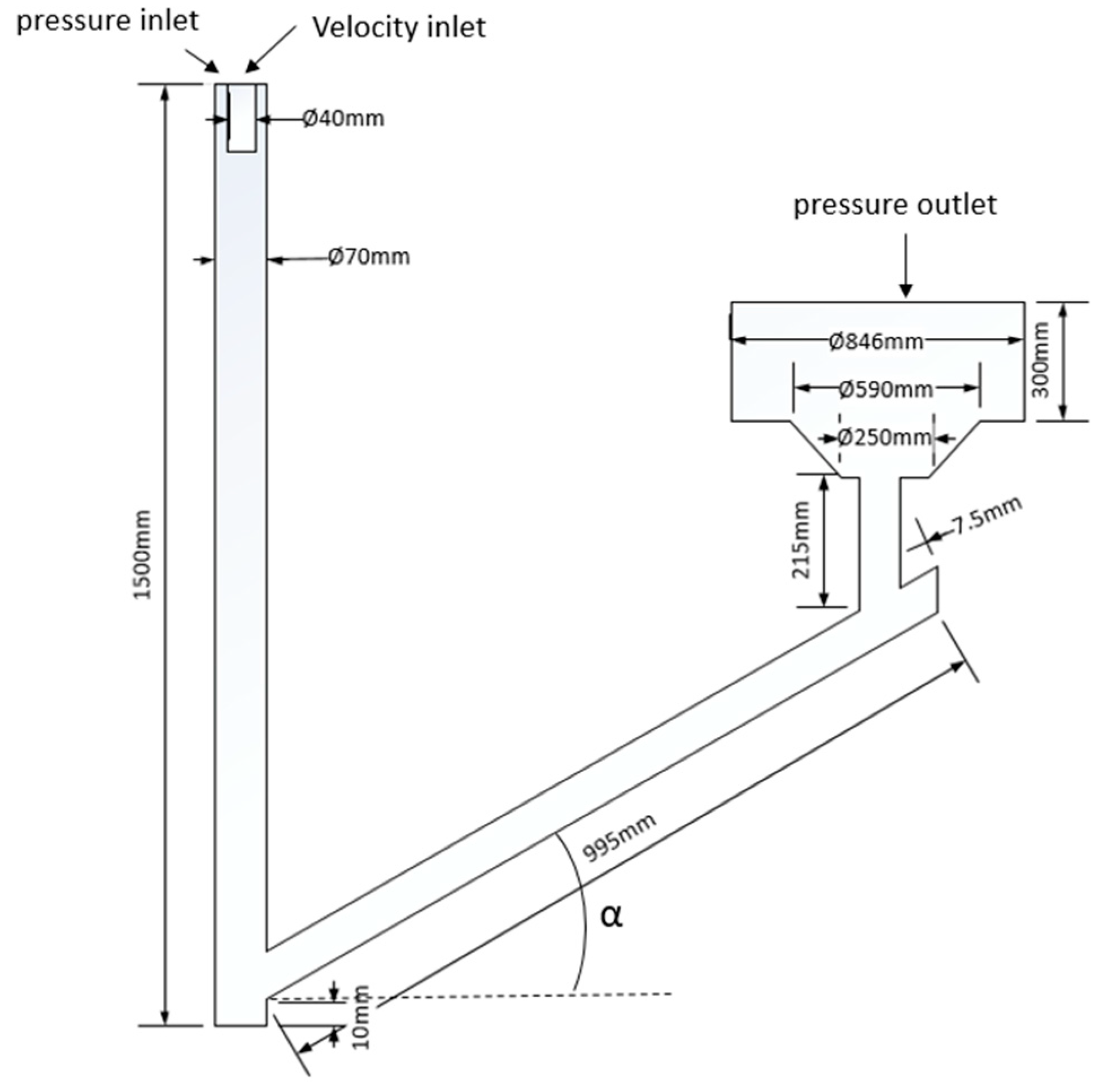
A three-dimensional model of a one mold gating system is adopted in the present study. All the dimensions are kept the same as used by the previous researcher Tan et al. [19] for the reference case, except for the height of the trumpet. In the present simulation, the height of the trumpet is 1.5 m while the trumpet height in Tan’s case was 2.61 m. This was done to reduce the simulation time. For the angled runner case, the angle (see α in Figure 3) between the runner and the trumpet was adopted as 10, 20, and 30 degrees in the current study. Typically, the diameter of the trumpet is 70 mm and the diameter of the runner is 45 mm. In addition, a reference simulation was also performed with a 90 degree angle between the runner and the trumpet. The computational domain is shown in Figure 3 and Figure 4.
2.1. Numerical Assumptions
In order to have a more intensive understanding of the flow pattern of the liquid steel in the uphill teeming process, some other factors are neglected. For instance, both air and steel are treated as incompressible Newtonian fluids, the physical properties of liquid steel and air are assumed to be constant during the numerical simulation, while chemical reactions are not simulated in this work. In addition, solidification and heat transfer are not considered in the present work.
2.2. Governing Equation
According to the assumption above, the governing equation can be written in the following form [20]:
where ρ is density, Φ is the conserved property, t is time, u is the mean velocity vector, Г is the diffusion coefficient, and SΦ is the source term. The various transport equations together with the realizable k-ε model are shown in Table 2.
2.3. Volume of Fluid Model
Hirt and Nichols [21] developed the volume of fluid method, it was adopted in the present work for tracking the free surface of the molten steel at the air/liquid interface. Both air and the molten steel phases were included in the simulation. The properties of air and molten steel are listed in Table 3. The time dependent volume fraction of fluid, F, is governed by the following equation:
The volume fraction F can be expressed by the following three conditions:
2.4. Boundary Conditions
The velocity inlet is located at the center of the inlet boundary and a constant velocity of 5.37 m/s which is calculated based on the Tan et al. [19] case was adopted in the present case. The mass flow rate was kept the same as Tan’s case. However, the inlet velocity increased to 5.37 m/s, due to the trumpet height was reduced to the 1.5 m in present work. As a consequence, the velocity of the liquid steel was increased due to the acceleration of gravity, while the inlet area was deceased to fix the same mass flow rate. The outer part of the inlet was set to a pressure inlet to allow gas to be entrained. The pressure outlet is located at the entrance of the mold and a zero-gauge pressure was applied. Also, the boundary conditions at the wall were set to “no slip” and the turbulence quantities, k and ε, were set to 1.4 × 10⁻²/s2 and 0.1 m2/s [19], respectively. Finally, a standard wall function was applied for the boundary condition at the walls.
2.5. Method of Solution
Numerical simulations were done by using the commercial CFD software ANSYS Fluent 19.2 (ANSYS, Canonsburg, PA, USA). The number of cells used in the simulations were determined by carrying out a mesh sensitivity study, as described below. The meshing was done in ANSYS workbench. Furthermore, the PRESTO discretization method was applied to discretize the pressure. The coupled scheme was used to solve the pressure-velocity coupling. The second order upwind scheme was adopted to solve the momentum equations, and the first order upwind schemes were used to calculate the turbulent kinetic energy and turbulent dissipation rate. In addition, the Courant number of VOF was fixed at 0.25. Finally, the realizable k-ε model was applied to calculate turbulence [19].
3. Results and Discussion
3.1. Mesh Sensitivity Study
A mesh sensitivity study was adopted in the present work. The case with a 30 degree angled runner was used to represent the angled runner case for the mesh sensitivity study. This is due to that the 10, 20, and 30 degrees angled runners have almost the same kind of mesh, while the angle is different. The number of cells in the 30 degree angled runner simulation and the reference simulation are shown in Table 4. The values of the velocities are reported as a solution ϕk of the different grids for the mesh sensitivity study at fixed points and times. The velocities at point (0.6, 0, and 0.37) and the time 1.85 s are listed in Table 4 for angled runner system. Due to the different geometry, the point (0.46, 0, and 0.017) and time 1.85 s were taken to measure the velocity in the reference simulation.
By substituting the velocity ϕ into Equations (4)–(9), the numerical uncertainty value GCI for fine mesh were calculated as 0.22% in the 30 degree angled runner simulation and 0.36% in the reference simulation [22]. It shows an extremely low uncertainty value for the fine mesh with both the angled runner simulation and the reference simulation. Therefore, the fine mesh in both systems are adopted in the present simulations. Meanwhile, the number of cells is kept around 570 thousand for the 10 and 20 degree angled runners.
where ΔVi is the volume, ε32 = ϕ3 – ϕ2, ε21 = ϕ2 – ϕ1, .
3.2. The Height of the First Molten Steel Jet
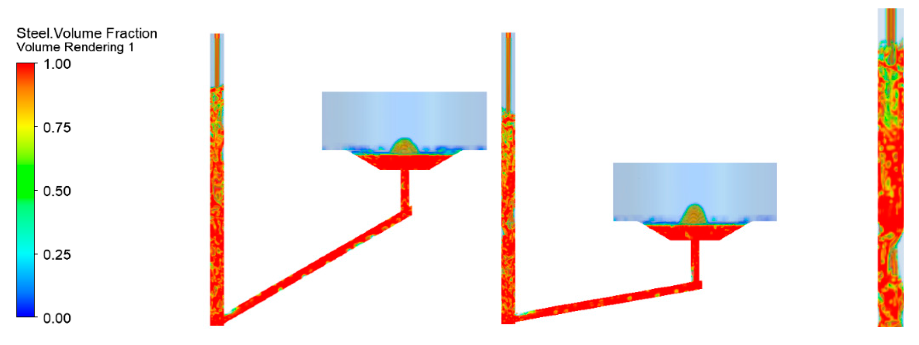
The flow patterns of the initial steel filling process for both the angled runner system and the reference system are shown in Figure 5. Due to gravity, the molten steel falls down into the trumpet and reaches the center stone. Because of the geometry of the center stone, the molten steel diverges into two parts at the center stone junction. The main flow splashes backwards into the trumpet itself. While the minor flow hits the upper wall of the runner and then scatters. Thereafter, the steel height in the trumpet increases dramatically. The implementation of an angled runner in the gating system decreases the mean velocity in the runner, due to gravity acceleration during the initial filling stage. In addition, the angled runner hinders the steel coming into the vertical runner. This causes the angled runner to fill up slower compared to a case with a horizontal runner. The splashed steel in the trumpet starts falling back and results in a surge of waves in the horizontal runner compared to the angled runner. This is because the gravity acceleration in the angled runner slows down the velocity of the liquid steel, which results in a slight wave in the angled runner. Meanwhile, it also contains less entrapped air in the angled runner compared to the horizontal runner.
As teeming continued, the molten steel moves along the runner and then results in a chaotic initial filling when steel enters into the mold. Thereafter, the first liquid hump height is formed due to the high-speed filling during the initial filling stage. The height of the first steel jet is an important factor from a production point-of-view. The lower initial hump height, as well as turbulence, can help the production personnel add the mold powder as early as possible. Nowadays, the mold powder bags are typically hung 100–200 mm above the mold bottom [23]. If this position for powder bags could be lowered, the chance for re-oxidation could be lower. It should be noticed that Eriksson et al. [24] carried out some experiments with and without the use of mold powder during the filling of a mold for production of an aluminum-killed bearing steel grade. The aim was to compare the influence of re-oxidation rate during the filling of the mold. Specifically, the result showed that a large number of new types of inclusions containing MnO were formed along with more alumina inclusions when no mold powder was used compared to the case with the use of mold powder during the short filling time of the ingot. It should be mentioned that the mold powder was added when the ingot was filled with molten steel. Based on Eriksson et al. [24] results, it can be concluded that re-oxidation by air will result in more and new types of inclusions. Thus, a lower hump height during the initial filling can result in the lower placement of the powder bags. Also, a lower height of the mold powder bags can prevent the molten steel to interact with air, which means fewer inclusions will be generated due to re-oxidation. Table 5 shows the first steel jet height for four different cases, where the height of the first steel jet is the distance between the bottom of the mold and the top point of the steel jet.
Generally, it can be seen that the reference case has the highest hump height where the first steel jet reaches a location 0.33 m above the bottom of the mold. The hump height of first steel jet for the angled runner with 10 degree decreases the height by 34% compared to the reference case. The height of the first steel jet decreases with an increased angle. The 30 degree angled runner has the lowest height for the first steel jet, which is 52% lower compared to the reference case. It can be noticed that the higher angle will facilitate the possibilities of adding mold powder closer to the bottom of the mold. However, when changing the angle from 20 to 30 degree, the height of the first steel jet decreases by 3.6%, which is a much smaller difference compared to the reference case and angled runner cases. The results show that angled runner can greatly decrease the initial hump height compared to the reference case. However, comparing the angled runner from a small angle to a higher angle, the differences in the initial hump height are smaller compared to the extent between the angled runner and the reference case.
3.3. Hump Height during the Initial Filling Process
As discussed above, the first steel jet height is important for the placement position of the mold powder bags, in order to prevent re-oxidation from the air. However, when steel enters the mold, some new types of inclusions are also formed from the chemical interaction between the molten steel and the mold powder. The flow pattern in the mold filling process is also important, which can result in mold flux entrapments in the mold. Zhang et al. [2] also found that large size inclusions from the entrapped mold flux were presented in the industrial-cast bottom-teemed ingots. Thus, it is of great importance to investigate the hump height during the filling of the mold.
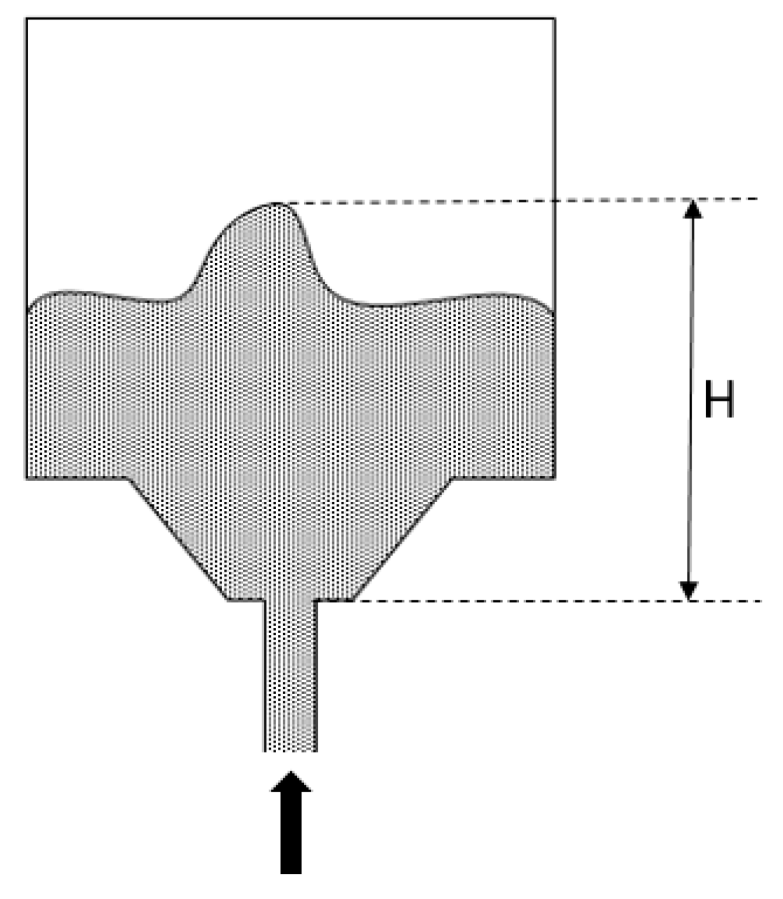
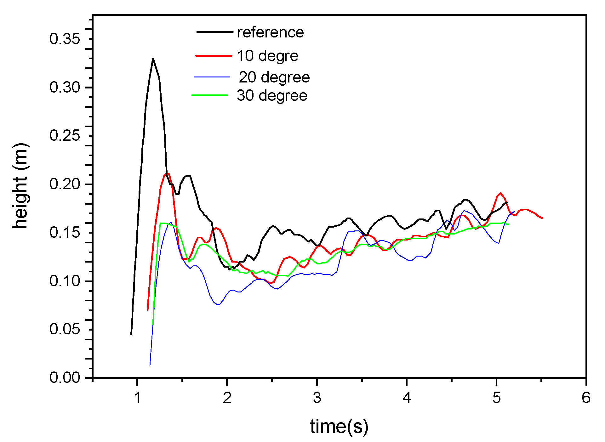
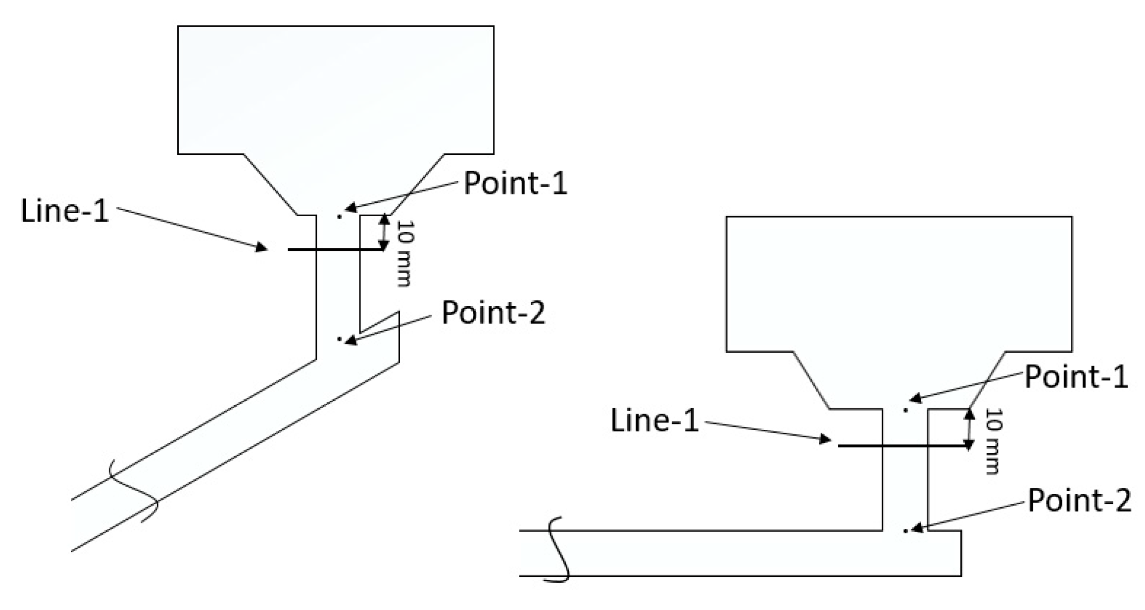
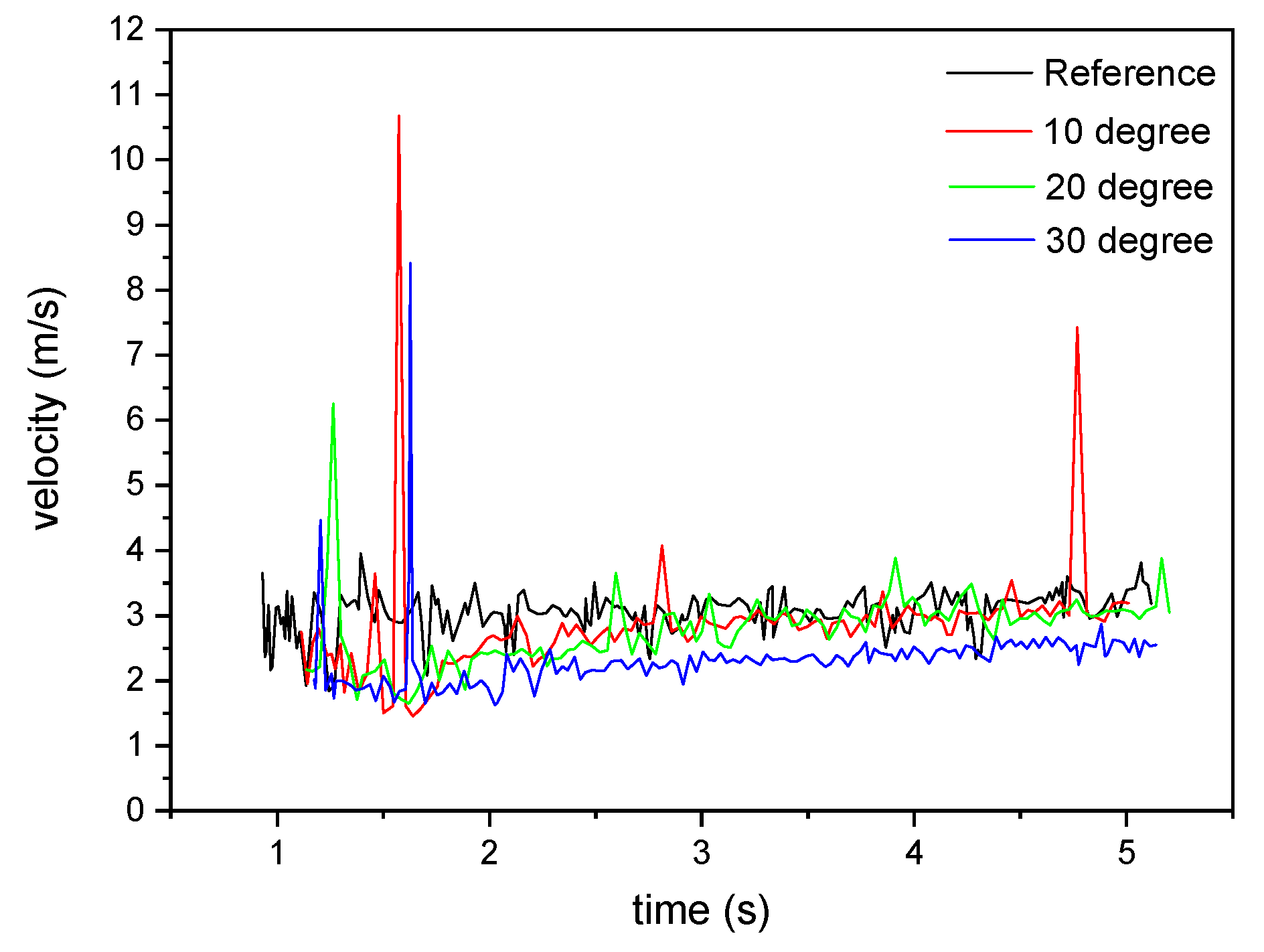
The definition of the hump height H is shown in Figure 6. The steel hump height varies with the filling time, as can be seen in Figure 7. It can be found that the highest hump height is generated in the beginning of the filling for all cases when the molten steel enters the mold. The reason is that there is no liquid steel in the mold, which can provide a flow resistance for the incoming flow. Thus, the highest hump is formed in the beginning stage of the filling process. When the teeming continues, some liquid steel stays in the mold which acts as a flow resistance as well as a buffer for the incoming flow. Therefore, the resulting hump heights are lower than that of the first steel jet. It can be noticed that the hump heights and the fluctuation rates are highest in the reference case compared to the angler runner cases. In addition, it can also be found that the fluctuation of the hump height is highest in the beginning when molten steel enters the mold for all the cases. This is due to the higher concentration of entrapped gas during the early stage of the filling, which can be seen in Figure 8. The fluctuation of the hump height is formed due to two main factors. One is the existence of the entrapped air during the filling stage. Tan et al. [10] found that less air entrapment can result in a calmer filling due to the escape of trapped air when forming the hump height. The other factor is the unevenness of the flow pattern. Hallgen et al. [25] investigated the flow pattern in the traditional ingot casting process. The researchers found that the velocity is higher at the right-hand side of the vertical runner and lower at the left-hand side of the runner in the steady state. The present work was simulated in a transient case, where the trumpet is placed on the left-hand side. Thus, the axial velocity profile changes over time. However, the axial velocity profile can be plotted for a specific time, in order to compare the difference of the unevenness of the axial velocity for different cases. Figure 9 and Figure 10 show the axial velocity profile at 2 and 5 s for all the cases along line-1, as can be seen in Figure 11. It can be noticed that the axial velocity at the right-hand side of the vertical runner is higher compared to the axial velocity at the left-hand side for all cases. These results are in good agreement with Hallgren et al. [25] research results. However, it is obvious that the axial velocity increases dramatically from the left-hand side to the right-side of the vertical runner in the reference case compared to the angled runner cases. For the angled runner cases, it can be observed that the increasing trend of the axial velocity along line-1 decreases as the angle increases. Specifically, the 30 degree angled runner has a smooth increasing trend of the axial velocity. In other words, the higher angled runner result in a less uneven flow. This can result in a calmer filling during the initial filling process. The 30 degree angled runner results in a much smoother axial velocity profile along line-1 at both 3 and 5 s compared to the other cases. Although it is hard to plot the axial velocity along line-1 during the whole filling process, point-1 and point-2 (see Figure 11) are used to monitor the velocity during the first 5 s of the filling. It can be found from Figure 12 that the velocity is highest at point-1 in the reference case during the filling time. In addition, the velocity decreases with the increase of the angle. It is because the higher angle result in a higher transformation of the steel momentum to gravitational potential energy. Thus, the 30 degree angled runner has the lowest velocity at point-1 during the initial filling process. For point-2, which is located near the mold entrance, it can be noticed from Figure 13 that the 30 angled runner results in less velocity fluctuations compared to other cases. It means that the velocity profile does not change much during the initial filling process. Considering the air entrapment in the vertical runner, it can be concluded that the 30 degree angled runner contains less entrapped gas with less unevenness of velocity during the initial filling process. As a consequence, it has a much steadier increase of the hump height during the initial filing process, as seen in Figure 5. Compared to the 20 degree angled runner, it has almost the same amount of entrapped gas as an angled runner with a 30 degree angle. However, the fluctuations of the velocity are higher compared to the case with a 30 degree angle. This in turn means that unevenness of the velocity profile changed a lot during the initial filling process. Thus, the hump height for the case with a 20 degree angled runner has higher fluctuations compared to the case with a 30 degree angled runner. Moreover, the 30 degree runner contains less entrapped air in the vertical runner and a steady unevenness of velocity compared to the other cases. Thus, the behavior of the hump height is good since it is smooth and has less fluctuation.
3.4. Thermodynamic Calculations
In the CFD simulations discussed above, the chemical reactions are not considered. In reality, some chemical reactions will take place in the filling system. The CFD simulations demonstrate that the system has a continued gas entrapment, which can be seen in Figure 8. The oxygen in the air bubbles can react with carbon in the liquid steel to form new gaseous species such as CO or CO2. These products can result in an increase of the bubble sizes. On the other hand, nitrogen and oxygen can also be dissolved into the liquid steel. The atomic net flux across the liquid/gas interface determines the size change of the bubble. The bubble expands if the amount of the carbon atoms joining the gas is larger than the oxygen (and nitrogen) content that is being dissolved in steel. In contrast, the bubble shrinks when more O (and N) leaves the bubbles compared to C being added to the bubbles. The bubble size is a significant parameter in the ingot casting process, since the bubble can result in a low-pressure region.
In the present work, the Thermo-Calc software together with its TCFE7 database was used to predict the thermodynamic equilibrium between the liquid steel and the gas phase. Specifically, the resulting gas volume (i.e. the air bubble size) was investigated based on the equilibrium calculations.
For the sake of simplicity and not losing the representativeness, only the chemical elements C and Fe in the liquid steel are considered, since carbon is the most dominant gaseous species-former. The carbon content in the steel is considered to be 0.22 wt.% in the ingot casting process [26]. For air, the main contents are nitrogen and oxygen. In the present thermodynamic calculations, only oxygen (21 vol.%) and nitrogen (79 vol.%) are considered. Thus, the other constituents like He and Ne are neglected. In addition, all the calculations are done in equilibrium state. The conditions in the calculation are listed in Table 6.
One mole of air is chosen as the fixed value for the initial air bubble and the supply of the liquid steel is considered as a variable in the calculations. The volume value of one mole air bubble in the equilibrium state can be calculated as 0.154 m3 using the following relationship (Equation (10)) that is valid for an ideal gas:
where P is pressure, V is volume, n is number of moles, R is the gas constant, and T is the absolute temperature.
PV = nRT
Figure 14 shows the change of the size during the filling operation. It can clearly be seen that the volume of the final gas increases in the beginning when liquid steel starts to fill the mold. After reaching its maximum value (0.177 m3), the gas size starts to decrease with a further increase of the system size. Thereafter, it becomes zero at a system size of around 1900 moles. It can also be noticed that the final bubble size is larger than the initial one for the system size between 20 and 260 moles. In other words, the bubble size increases when 20–260 moles of steel are involved in chemical reactions. In a larger region, the bubble size decreases when more steels join the equilibrium. The volume of steel is extremely small compared to the volume of air in the beginning, since the density of steel is almost 7000 times larger than that of air. According to the calculation, a 0.154 m3 gas volume is equivalent to one mole of air. Meanwhile, the same size of the liquid steel is about 36,600 moles. In the beginning of the filling process, a small size of liquid steel exists compared to air. Due to the limited oxygen solubility, the steel can only accommodate small amounts of O during the early filling stage. Meanwhile, the C atoms in the steel react with the gas to form gaseous species such as CO or CO2. As a result, the bubble expands. As the filling of the liquid steel continues, more carbon atoms are transferred from the liquid to the gas phase. With 20 moles of liquid steel, the size of the gas is bigger than the initial size. The bubble volume to a maximum size of 0.17 m3 with a steel input of 60 mole, which contains 0.062 m3 of CO and 0.115 m3 of nitrogen (the initial condition is 0.154 m3 which contains 0.123 m3 nitrogen and 0.031 m3 oxygen). Our thermodynamic equilibrium calculation shows that the carbon reacts with oxygen to form carbon monoxide. Furthermore, that only a small amount of nitrogen is dissolved into the liquid steel. Thus, the bubble size increases during this stage of the process. With an increased steel amount, the ability to dissolve O and N increases proportionally. Filling more molten steel than 60 moles in the system, results in that more O and N will be dissolved into the steel compared to the amount of C being transferred into the gas. In the end, all O and N in the initial bubbles will be dissolved into the large amount of liquid steel. In the present ingot casting system, the volume of liquid steel that occupies most of the place in the system compared to the gas phase. Table 7 shows the gas fraction in the runner at 5 s for all the simulation cases. It can be point out that the volume of liquid steel is almost 9 times bigger compared to the volume of gas. Thus, assuming the volume of liquid phase is 9 times larger than the gas phase (0.154 m3). The liquid steel is about 171 kmol (see Table 8). Thus, the gas will be totally dissolved into the liquid steel if the reaction reaches a thermodynamic equilibrium. However, the reaction kinetics have to be considered during the present initial filling stage. In addition, the diffusivity of C in steel is faster than that of O and N. Therefore, the gas phase will not be completely dissolved during the present process. With the above thermodynamic calculation, it can be concluded that the bubble most likely shrinks in the present system. However, it may not be totally absorbed into the liquid steel during the initial filling process.
3.5. Drawbacks of the Angled Runner System
As mentioned earlier, the angled runner system leads to an improvement of the flow pattern during the initial filling stage in the ingot casting process and a lower placement for powder bags can be achieved with a higher angled runner. Besides, 30 degree angled runner has a calmer hump height compared to other cases during the initial filling stage. However, there are also some drawbacks when using the angled runner system. First of all, in order to make an angled runner, the length of the runner is increased compared to the reference case. The increase of the runner will result in a loss of steel in the horizontal runner when the process is finished. Thus, this raises the costs of making a larger refractory piece. Besides, it is a little bit hard to place the angled runner system, since the horizontal runner is mounted underground. The use of an angled runner system makes it necessary to put the system even deeper underground. Thus, this also makes it hard to maintain the angled runner system. However, overall the angled runner system, it is a rather simple way to improve the flow pattern in the ingot casting system.
4. Conclusions
The effect of implementing of an angle runner in the uphill teeming process on the filling conditions was investigated. Both the angled runner cases and a reference system including a trumpet and runners were studied. The overall conclusion reached from the study’s findings was that a utilization of 30 degree of angled runner markedly improved the fluid-flow conditions during the filling compared to other reference cases, which result in a steady increase of the hump height. In addition, the following specific conclusions may be stated based on the results from the current study.
- (1)
- The height for the first steel jet in the mold is highest in the reference case. For the angled runner cases, the height for the first steel jet decreases as the angle increases. Meanwhile, the lower height of the first steel jet can result in a lower placement of powder bags which reduces the re-oxidation rate. The 30 degree angled runner decrease the height of first steel jet by 52%.
- (2)
- Angled runner cases show a good improvement in hump height and fluctuation rate compared to the reference case during the initial filling process. Specifically, the maximum hump height decreases 36%, 52% and 0.51% for 10, 20, and 30 degrees angled runner compared to the reference case.
- (3)
- The 30 degree angled runner case shows a smoother increase of hump height compared to other cases during the initial filling process.
- (4)
- The amount of entrapped gas in the vertical runner decreases as the angle increases, while the 20 degree and 30 degree has almost the same amount of entrapped gas.
- (5)
- From the thermodynamic calculations, it is clear that the bubble will shrink over time due to the dissolution of O and N into steel.
Author Contributions
Conceptualization, M.E., H.M. and P.G.J.; software, J.Y. and H.M.; formal analysis, J.Y.; investigation, J.Y.; writing—original draft preparation, J.Y.; writing—review and editing, M.E., P.G.J. and H.M.; supervision, M.E. and P.G.J.
Funding
This research received no external funding.
Acknowledgments
The China Scholarship Council (CSC) is acknowledged for the financial support to this study.
Conflicts of Interest
The authors declare no conflict of interest.
References
- World Steel Association. Steel Statistical Yearbook 2018; World Steel Association: Brussels, Belgium, 2018; p. 121. [Google Scholar]
- Zhang, L.; Rietow, B.; Thomas, B.G.; Eakin, K. Large inclusions in plain-carbon steel ingots cast by bottom teeming. ISIJ Int. 2006, 46, 670–679. [Google Scholar] [CrossRef]
- Pola, A.; Gelfi, M.; La Vecchia, G. Comprehensive numerical simulation of filling and solidification of steel ingots. Materials 2016, 9, 769. [Google Scholar] [CrossRef] [PubMed]
- Liu, X.; Lienhard, J. The hydraulic jump in circular jet impingement and in other thin liquid films. Exp. Fluids 1993, 15, 108–116. [Google Scholar] [CrossRef]
- Lienhard, J.H. Heat transfer by impingement of circular free-surface liquid jets. In Proceedings of the 18th National and 7th ISHMT-ASME Heat and Mass Transfer Conference, Guwahati, India; 4–6 January 2006. [Google Scholar]
- Lienhard, J.H.; Khounsary, A.M. Liquid Jet Impingement Cooling with Diamond Substrates for Extremely High Heat Flux Applications; Technical Report; Argonne National Laboratory: Lemont, IL, USA, 1993; pp. 29–44. [Google Scholar]
- Hurtuk, D.J. Steel ingot casting. In Casting; ASM Handbook, ASM International: Materials Park, OH, USA, 2008; Volume 15, p. 911. [Google Scholar]
- Eriksson, R.; Jonsson, L.; Jönsson, P.G. Effect of Entrance Nozzle Design on the Fluid Flow in an Ingot Mold during Filling. ISIJ Int. 2004, 44, 1358–1365. [Google Scholar] [CrossRef] [Green Version]
- Freborg, M. Reoxidation Prevention in Bottom Poured Ingot Production—A Systems Approach. In Proceedings of the 50th Electric Furnace Conference Proceedings, Atlanta, GA, USA, 10–13 November 1992; p. 235. [Google Scholar]
- Tan, Z.; Ersson, M.; Jonsson, P.G. Modeling of initial mold filling with utilization of swirl blades. ISIJ Int. 2012, 52, 1066–1071. [Google Scholar] [CrossRef]
- Cheng, J.; Eriksson, R.; Jönsson, P. Determination of macroinclusions during clean steel production. Ironmak. Steelmak. 2013, 30, 66–72. [Google Scholar] [CrossRef]
- Pathak, N.; Kumar, A.; Yadav, A.; Dutta, P. Effects of mould filling on evolution of the solid–liquid interface during solidification. Appl. Therm. Eng. 2009, 29, 3669–3678. [Google Scholar] [CrossRef]
- Kermanpur, A.; Eskandari, M.; Purmohamad, H.; Soltani, M.; Shateri, R. Influence of mould design on the solidification of heavy forging ingots of low alloy steels by numerical simulation. Mater. Des. 2010, 31, 1096–1104. [Google Scholar] [CrossRef]
- Franke, D.; Rettelbach, T.; Häßler, C.; Koch, W.; Müller, A. Silicon ingot casting: process development by numerical simulations. Sol. Energ. Mat. Sol. C 2002, 72, 83–92. [Google Scholar] [CrossRef]
- Ge, H.; Ren, F.; Li, J.; Hu, Q.; Xia, M.; Li, J. Modelling of ingot size effects on macrosegregation in steel castings. J. Mater. Process. Technol. 2018, 252, 362–369. [Google Scholar] [CrossRef]
- Gu, J.P.; Beckermann, C. Simulation of convection and macrosegregation in a large steel ingot. Metall. Mater. Trans. A 1999, 30, 1357–1366. [Google Scholar] [CrossRef] [Green Version]
- Ragnarsson, L.; Ek, M.; Eliasson, A.; Sichen, D. Flow pattern in ingot during mould filling and its impact on inclusion removal. Ironmak. Steelmak. 2013, 37, 347–352. [Google Scholar] [CrossRef]
- Bai, H.T.; Ersson, M.; Jonsson, P. Effect of TurboSwirl structure on an uphill teeming ingot casting process. Metall. Mater. Trans. B 2015, 46, 2652–2665. [Google Scholar] [CrossRef]
- Tan, Z.; Ersson, M.; Jönsson, P.G. Mathematical modeling of initial filling moment of uphill teeming process considering a trumpet. ISIJ Int. 2011, 51, 1461–1467. [Google Scholar] [CrossRef]
- Versteeg, H.K.; Malalasekera, W. An Introduction to Computational Fluid Dynamics: The Finite Volume Method; Pearson Education Limited: London, UK, 2007. [Google Scholar]
- Hirt, C.W.; Nichols, B.D. Volume of fluid (Vof) method for the dynamics of free boundaries. J. Comput. Phys. 1981, 39, 201–225. [Google Scholar] [CrossRef]
- Celik, I.B.; Ghia, U.; Roache, P.J.; Freitas, C.J. Procedure for estimation and reporting of uncertainty due to discretization in CFD applications. J. Fluid Eng. Trans. ASME 2008, 130, 078001. [Google Scholar]
- Hallgren, L.; Tilliander, A.; Yokoya, S.; Jönsson, P.G.; Hagman, S. A first attempt to implement a Swirl blade in production of ingots. ISIJ Int. 2010, 50, 1763–1769. [Google Scholar] [CrossRef]
- Eriksson, R.; Jönsson, P.; Gustafsson, A. Determination of inclusion characteristics in ‘low-carbon’ steel during up-hill teeming. Scand. J. Metall. 2004, 33, 160–171. [Google Scholar] [CrossRef]
- Hallgren, L.; Takagi, S.; Eriksson, R.; Yokoya, S.; Jönsson, P. Effect of nozzle Swirl blade on flow pattern in runner during uphill teeming. ISIJ Int. 2006, 46, 1645–1651. [Google Scholar] [CrossRef]
- Lesoult, G. Macrosegregation in steel strands and ingots: Characterisation, formation and consequences. Mater. Sci. Eng. A Struct. 2005, 413, 19–29. [Google Scholar] [CrossRef]
Figure 1.
Schematic diagram of the uphill teeming process.

Figure 2.
Schematic diagram of investigated region.

Figure 3.
Schematic diagram of the computational domain with an angled runner.

Figure 4.
Schematic diagram of the computational domain of the reference simulation.

Figure 5.
Contour of liquid steel during ingot filling process at 5 s from teeming start and a close-up trumpet zone (with 10 and 30 degree angled runners).
Figure 5.
Contour of liquid steel during ingot filling process at 5 s from teeming start and a close-up trumpet zone (with 10 and 30 degree angled runners).

Figure 6.
Definition of hump height H.

Figure 7.
Variation of hump height with filling time for the reference case and angled runner cases.
Figure 7.
Variation of hump height with filling time for the reference case and angled runner cases.

Figure 8.
Volume fraction of air in the vertical runner as a function of time.

Figure 9.
Axial velocity after 2 s along line-1 seen in Figure 10.
Figure 9.
Axial velocity after 2 s along line-1 seen in Figure 10.

Figure 10.
Axial velocity after 5 s along the line-1 seen in Figure 10.
Figure 10.
Axial velocity after 5 s along the line-1 seen in Figure 10.

Figure 11.
Two points and one line for monitoring the velocity in angled runner cases and the reference case.
Figure 11.
Two points and one line for monitoring the velocity in angled runner cases and the reference case.

Figure 12.
Velocity variation with time at point-1 for all cases.

Figure 13.
Velocity variation with time at point-2 for all cases.

Figure 14.
Volume of gas vary with system size in equilibrium state.


Table 1.
Investigated region by different researchers in an ingot casting process.
| Region | Researchers | References |
|---|---|---|
| I | Freborg | [9] |
| II | Zhang | [2] |
| III | Bai | [18] |
| IV | Eriksson | [8] |
| V | Cheng, Ge, Gu and Tan | [11,15,16,19] |
Table 2.
Conservation equations.
| Conversation of: | Φ | Г | SΦ |
|---|---|---|---|
| Mass | 1 | 0 | 0 |
| x-momentum | u | μ | |
| y-momentum | v | μ | |
| z-momentum | w | μ | |
| Turbulent kinetic energy | κ | Gk − ρε | |
| Turbulent dissipation rate | ε | ||
| Notes: | |||
| |||
| |||
| |||
| |||
| |||
Table 3.
Physical properties of air and molten steel [19].
Table 3.
Physical properties of air and molten steel [19].
| Density (kg/m3) | Dynamic Viscosity (Pa·s) | |
|---|---|---|
| Air | 1.225 | 1.7894 × 10⁻⁵ |
| Molten steel | 6900 | 0.006 |
Table 4.
Number of cells and the predicted velocities in both the angled runner case and the reference case.
Table 4.
Number of cells and the predicted velocities in both the angled runner case and the reference case.
| Mesh | Number of Cells in the Angled Runner case | Number of Cells in the Reference Case | Predicted Velocities in the Angled Runner Case (m/s) | Predicted Velocities in the Reference Case (m/s) |
|---|---|---|---|---|
| Coarse mesh | 139,462 | 105,814 | 1.80954 | 2.16741 |
| Medium mesh | 281,246 | 241,657 | 1.82921 | 2.21849 |
| Fine mesh | 571,087 | 544,404 | 1.76323 | 2.20331 |
Table 5.
Height for first steel jet.
| Case | Height of First Steel Jet (m) | Time (s) |
|---|---|---|
| Reference | 0.33 | 1.174 |
| 10 degree | 0.210 | 1.326 |
| 20 degree | 0.161 | 1.340 |
| 30 degree | 0.160 | 1. 439 |
Table 6.
Conditions for thermodynamic calculations.
| Pressure (Pa) | Temperature (K) | Air Bubble Size (mole) | Liquid Steel Size (mole) |
|---|---|---|---|
| 101,325 | 1873 | 1 | 2.4 to 2000 |
Table 7.
Volume fraction of gas in the runner at 5 s.
| Cases | Volume Fraction of Gas in the Runner |
|---|---|
| Reference case | 0.115 |
| 10 degree runner | 0.075 |
| 20 degree runner | 0.048 |
| 30 degree runner | 0.056 |
Table 8.
Calculation of gas and liquid phase.
| Phase | Volume(m3) | mole |
|---|---|---|
| gas | 0.154 | 1 |
| liquid | 1.386 | 170,775 |
© 2019 by the authors. Licensee MDPI, Basel, Switzerland. This article is an open access article distributed under the terms and conditions of the Creative Commons Attribution (CC BY) license (http://creativecommons.org/licenses/by/4.0/).
Share and Cite
MDPI and ACS Style
Yin, J.; Ersson, M.; Mao, H.; Jönsson, P.G. Mathematical Modelling of the Initial Mold Filling with Utilization of an Angled Runner. Metals 2019, 9, 693. https://doi.org/10.3390/met9060693
AMA Style
Yin J, Ersson M, Mao H, Jönsson PG. Mathematical Modelling of the Initial Mold Filling with Utilization of an Angled Runner. Metals. 2019; 9(6):693. https://doi.org/10.3390/met9060693
Chicago/Turabian StyleYin, Jun, Mikael Ersson, Huahai Mao, and Pär G. Jönsson. 2019. "Mathematical Modelling of the Initial Mold Filling with Utilization of an Angled Runner" Metals 9, no. 6: 693. https://doi.org/10.3390/met9060693
Note that from the first issue of 2016, this journal uses article numbers instead of page numbers. See further details here.