Computer-Aided Material Design for Crash Boxes Made of High Manganese Steels
by
 , , and
Angela Quadfasel
1,*, 
Marco Teller
1,
Manjunatha Madivala
2,
Christian Haase
2,
Franz Roters
3 and
Gerhard Hirt
1 1
Institute of Metal Forming (IBF), RWTH Aachen University, 52072 Aachen, Germany
2
Steel Institute (IEHK), RWTH Aachen University, 52072 Aachen, Germany
3
Max-Planck-Institut für Eisenforschung GmbH, 40237 Düsseldorf, Germany
*
Author to whom correspondence should be addressed.
Metals 2019, 9(7), 772; https://doi.org/10.3390/met9070772
Submission received: 14 June 2019
/
Revised: 2 July 2019
/
Accepted: 4 July 2019
/
Published: 10 July 2019
(This article belongs to the Special Issue Physical Metallurgy of High Manganese Steels)
Abstract
:During the last decades, high manganese steels (HMnS) were considered as promising materials for crash-relevant automobile components due to their extraordinary energy absorption capability in tensile tests. However, in the case of a crash, the specific energy, absorbed by folding of a crash box, is lower for HMnS as compared to the dual phase steel DP800. This behavior is related to the fact that the crash box hardly takes advantage of the high plastic formability of a recrystallized HMnS during deformation. It was revealed that with the help of an alternative heat treatment after cold rolling, the strength of HMnS could be increased for low strains to achieve a crash behavior comparable to DP800. In this work, a multi-scale finite element simulation approach was used to analyze the crash behavior of different material conditions of an HMnS. The crash behavior was evaluated under consideration of material efficiency and passenger safety criteria to identify the ideal material condition and sheet thickness for crash absorption by folding. The proposed simulation methodology reduces the experimental time and effort for crash box design. As a result of increasing material strength, the simulation exhibits a possible weight reduction of the crash box, due to thickness reduction, up to 35%.
1. Introduction
For crash-relevant components of the body-in-white design of vehicles, a combination of high strength and high plasticity is necessary to guarantee passenger safety and lightweight construction at the same time. This combination of mechanical material properties is provided by high manganese steels (HMnS). Due to the additional deformation mechanism of twinning, the group of TWIP (twinning-induced plasticity) steels exhibit the possibility of forming complex geometries in combination with a high impact-energy-absorption potential [1]. Strain hardening engineering can be applied on HMnS to adjust the hardening mechanism for ideal hardening behavior for specific applications. Bambach et al. [2] argued that a good crash performance for a crash box, built for frontal impact, is achieved by a high initial strength of HMnS. The works of Haase et al. [3,4] showed that recovery (RV) annealing is a simple, promising processing route to overcome the shortcoming of low yield strength usually associated with TWIP steels in recrystallized (RX) condition. While dislocation density of the cold rolled (CR) condition of a Fe-23Mn-1.5Al-0.3C is reduced during the RV annealing, the twin fraction remains constant, resulting in high yield strength with moderate formability. The material condition after RV annealing of Fe-23Mn-1.5Al-0.3C has been applied to the experimental crash test by drop tower tests and successfully increased the specific energy absorption of the crash box [2,5]. Due to the higher yield strength compared to the fully RX material condition, an increase of the energy absorption per mass was achieved and resulted in a shorter crash distance. In addition to material strength, the crash behavior and especially the buckling stress, which is necessary for initiation of the folds, is depending on the geometry of the crash boxes. Bambach et al. showed in their work [2] that the cross-section geometry of a crash box of the same material has a significant influence on the crashworthiness. While a square cross section needs a higher crash distance, the hexagon shape showed a performance nearly as good as a circular shape with the same cross-sectional area. Therefore, an additional degree of freedom exists in the design of a crash box in the form of the geometry. In this work, only a hexagonal cross section with constant diameter is used and the influence of geometry is only considered by a variation of the sheet thickness.
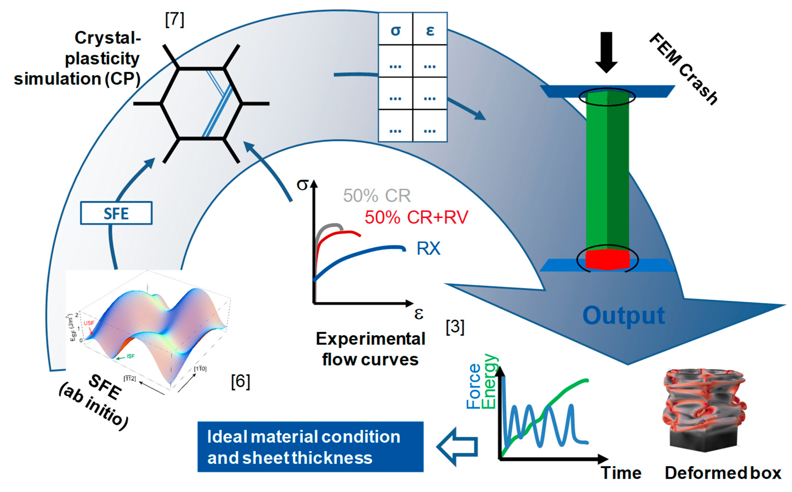
Experimental crash tests are very time consuming and expensive. In order to save costs, a computer-aided design of the ideal material condition and geometry design can be realized by finite element (FE) simulation in combination with sophisticated material models. In this work, an ICME (integrated computational material engineering) approach, depicted in Figure 1, is used to reduce the experimental effort of the crash box design. Material parameters of HMnS were calculated at different scales and used to predict the hardening behavior of different material conditions, which is finally used to simulate the crash behavior of a crash box. On the atomistic scale, the stacking fault energy of the HMnS was calculated by a combination of thermodynamic and ab initio calculations and was taken from [6]. The stacking fault energy (SFE) influences the activation of different deformation mechanisms, which are considered during the simulation of hardening behavior with a physics-based crystal plasticity (CP) model, which is described in detail in [7]. The flow curves of different material conditions are then used in FE simulation to predict the crash behavior. The consideration of the microstructure during FE simulation is necessary because the hardening behavior is significantly correlated to the microstructure and deformation mechanisms. Due to high deformation rates and high dissipation during the crash, the deformation mechanism can change. With the help of the ICME approach, different initial microstructures can be analyzed with respect to their influence on the crash behavior and give a direct insight into promising microstructure-design strategies.
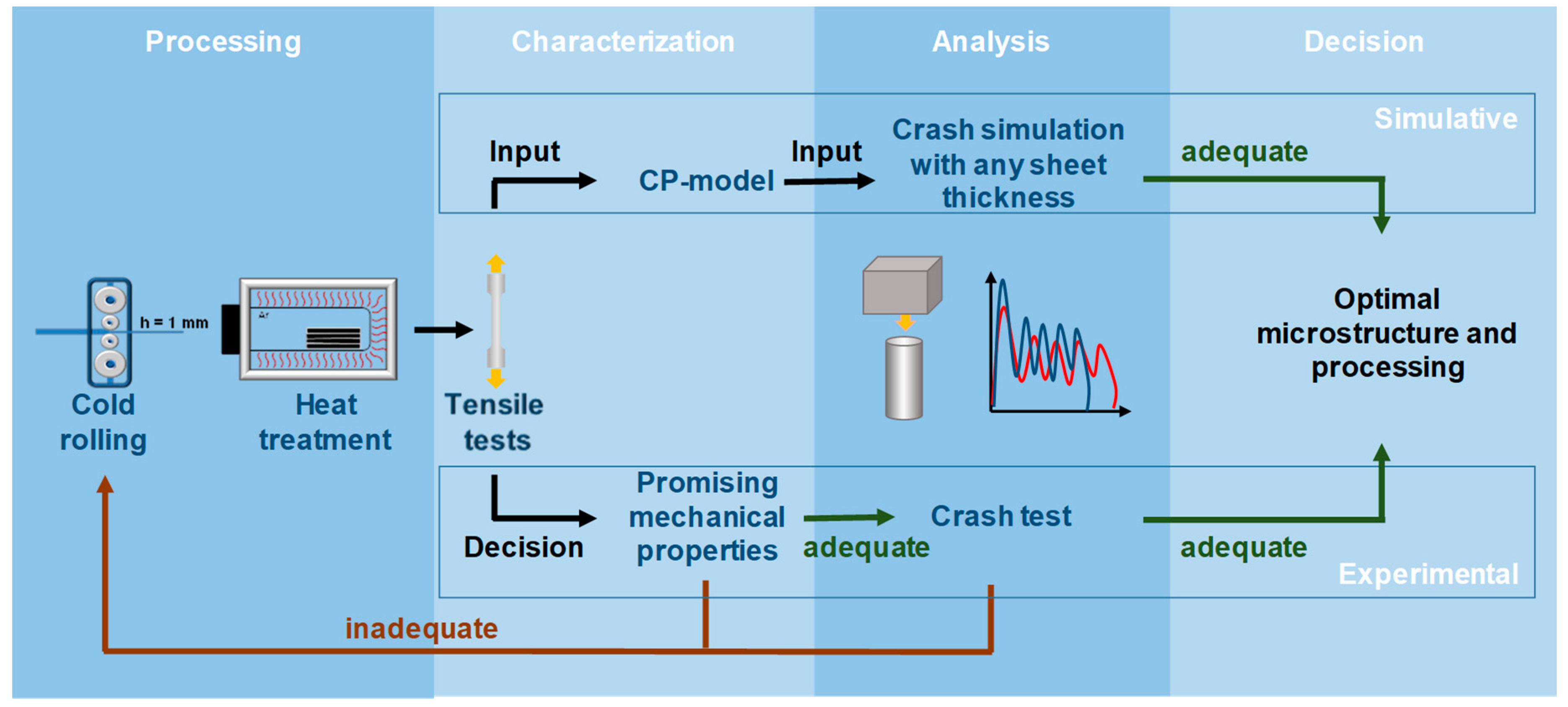
From an economic point of view, a successfully validated simulation chain enables the reduction of experimental effort. Figure 2 compares the steps for an experimental and a more simulation-based design of a crash box. The traditional experimental-based design process is coupled to a high number of crash experiments for the different material conditions. In the process chain of a crash box, cold rolling and heat treatment are the relevant process steps to define the sheet thickness as well as the material condition and therefore, the mechanical properties. Additionally, all different material conditions have to be tested in tensile tests to make a first choice based on simplified criteria like ECO-index, the product of ultimate tensile strength and uniform elongation, or buckling stress [2]. Both criteria allow for a first approximation of the energy absorption of different materials, while the buckling stress also considers the simplified geometry of a crash box. However, both criteria cannot replace the analysis of crash behavior under all boundary conditions. Another criterion, for example, is the mean deceleration to ensure passenger safety. A maximum value of 15 g (gravitational acceleration) for deceleration was identified as a limit by biomechanics specialists to avoid long-term damages due to whiplash in [8]. In order to be able to evaluate the crash behavior of the different material conditions, it is necessary establish their performance in drop tower tests.
The simulation-based design of a crash box should reduce the effort of drop tower tests and should give a direct correlation between crash behavior and microstructure. Based on that, a suggestion for the optimal processing strategy can be given. Also, for the simulation-based design, experimental tensile tests are necessary to validate the material model. However, the decision of which material conditions are suitable for the crash, can be made without further experimental crash tests. For the simulation-based design, only specific material conditions have to be tested in tensile tests to set up the material model, which can then simulate the plastic behavior of other material conditions. The optimal combination of material condition and box geometry can then be identified by simulation and, if necessary, validated for selected conditions with drop tower tests. In contrast, the experimental-based design needs an iterative adaption of the processing during the design process to identify an adequate material condition for the crash behavior.
In this work, the crash behavior of high manganese TWIP steel is optimized combining multi-scale simulation tools as well as knowledge from different material science and engineering disciplines to an ICME approach. Within this ICME approach, the crash behavior of the different material conditions was analyzed using flow curves of HMnS subjected to different degrees of cold rolling and additional RV annealing in FE simulation of drop tower tests. In addition to the previously mentioned criteria of crash distance, passenger safety in terms of deceleration was considered as a criterion for ideal crash performance. The aim of the work was to identify the ideal combination of material strength and sheet thickness of crash boxes to fulfill the criteria of passenger safety and lightweight construction at the same time.
2. Materials
2.1. Material and Characterization
The investigated material is a HMnS TWIP steel with 0.3 wt.% carbon, 23 wt.% manganese, 1 wt.% aluminum (X30MnAl23-1), and a stacking fault energy of ~25 mJm−2 [3]. The material was cast as 100 kg ingots at the Steel Institute (IEHK) of Rheinisch-Westfälische Technische Hochschule (RWTH) Aachen University (Aachen, Germany), homogenization-annealed at 1150 °C, and forged at 1150 °C at the Institute of Metal Forming (IBF). After an additional homogenization annealing, the 55 mm thick slabs were hot rolled at 1150 °C to 2.4 mm and then cold rolled in several passes to final thickness reductions of 30%, 40%, and 50%. Heat treatment parameters to achieve the recovered material condition for the different rolling degrees and the recrystallized material condition are based on the work of Haase et al. [3], given in Table 1.
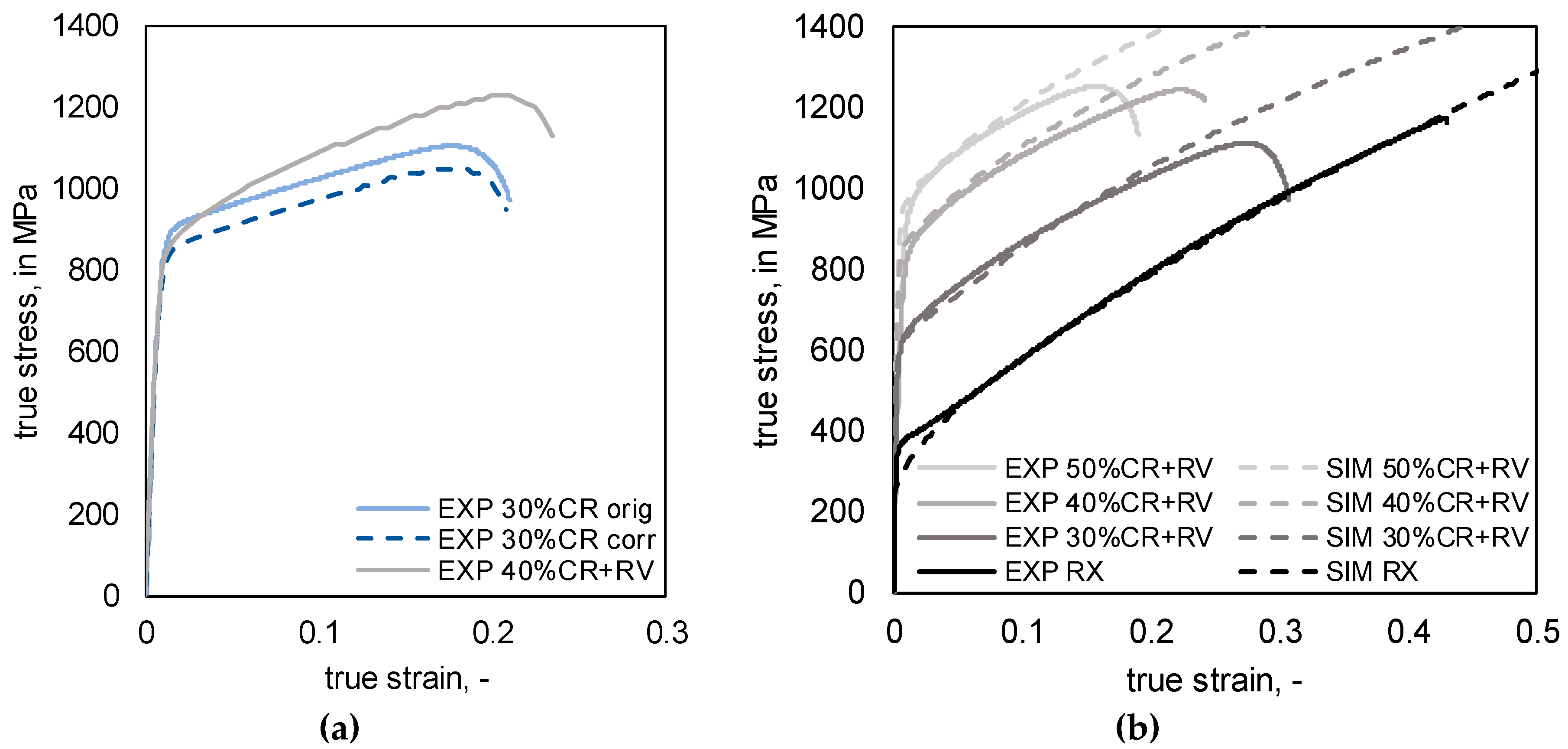
Uniaxial tensile tests (IEHK, Aachen, Germany) were performed to validate the material model for the different conditions. The result of two experimentally tested material conditions 30% CR and 40% CR + RV, with similar yield strength in the tensile test but different hardening rates are shown in Figure 3a. The experimental stress–strain curves for the different material conditions after recovery annealing with different yield strength are illustrated in Figure 3b. Moreover, simulated stress–strain curves, which are described in detail in Section 2.2, are shown.
2.2. Simulation of Plastic Behavior
The plastic deformation behavior of the high manganese steel in FE simulation can be described by the true stress–strain curve from the tensile test. For the investigation of the influence of hardening rate on the crash behavior, the flow curve of 30% CR (orig) in Figure 3a has been reduced manually (corr) by an offset of 50 MPa to achieve the same yield strength as 40% CR + RV.
The main advantage of the usage of a universal material model in the simulation chain is that different material conditions can be derived from one set of parameters after model calibration. The stress–strain behavior of the different material conditions after recovery annealing, as shown in Figure 3b, was simulated with the help of a representative volume element (RVE) using the spectral solver of the crystal plasticity (CP) package DAMASK (Düsseldorf Advanced Material Simulation Kit) developed by Max-Planck-Institut für Eisenforschung GmbH (Düsseldorf, Germany) [9]. In addition to dislocation density, the CP model considers the evolution of the twin volume fraction. Due to the dependence of twinning on the SFE, this temperature dependent parameter was calculated by a combination of Calculation of Phase Diagrams (CALPHAD) method and ab initio calculations [6]. The CP model was used to simulate the deformation behavior under plane strain compression conditions and resulted in the determination of the dislocation densities and twin volume fractions after cold rolling degrees of 30%, 40%, and 50%. A similar procedure is described in [3,10,11]. Afterwards, the corresponding dislocation densities for each cold rolling degree were used as input parameters for full field RVE simulations (using 100 grains) of the deformation behavior under uniaxial tensile loading conditions.
3. Methods
3.1. Drop Tower Experiments
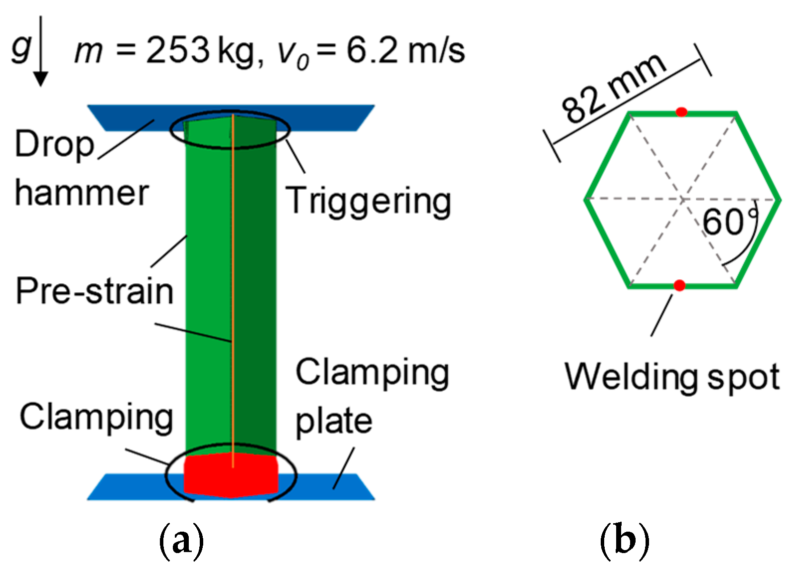
To validate the FE model used for simulation of the drop tower test, experimental crash tests were performed by the Forschungsgesellschaft Kraftfahrwesen mbH (FKA) (Aachen, Germany). For production of the crash boxes, the material was cold rolled to 1 mm sheet thickness with a thickness reduction of 50%. After heat treatment (RX and RV), 275 mm × 14 mm samples were bent to half hexagons, which were laser welded at the Fraunhofer Institute for Laser Technology (ILT) (Aachen, Germany) to hexagonal crash boxes with a diameter of 82 mm. The physical simulation of crash deformation of the box during uniaxial loading was performed using a drop tower. A mass of 253 kg and a height of 2.0 m resulting in a kinetic energy of ~5 kJ and an impact velocity close to 22 km/h were chosen for the tests. The crash box was fixed on the non-impact side. The top of the crash box was triggered by alternate bending of the edges 20 mm from the upper border, resulting in the opposite edges being bent in the same direction. The trigger is supposed to ease the initial bending, which leads to more regular folding.
3.2. FE Simulation of Drop Tower Test
The explicit FE simulation of the drop tower test was performed by the software ABAQUS 6.14-6 from Dassault Systemes Simulia Corp. (Johnston, IA, USA). Due to the high velocity of the crash tests, no mass scaling was needed for the performance of the simulations. The model consisted of a 3D deformable shell model of the hexagonal geometry meshed by 4-node general-purpose shell elements with reduced integration (S4R) of 2 mm edge length with hourglass control. The velocity of the 253 kg drop mass was set to 6.2 m/s for the moment of contact with the crash box. The contact between crash box and drop mass was defined as hard contact. The deceleration velocity of the drop mass was calculated in FE simulation by the converse effects of energy absorption of the crash box and the acceleration by gravity.
The geometry of the hexagonal crash box in Figure 4a,b was extended by a trigger following the trigger of the experimental crash boxes. In addition, a pre-strain, calculated by bending theory, at the vertical bending edges was used to consider the hardening due to bending during the production of the crash boxes. The plastic behavior of the simulated materials was assumed to be isotropic and was defined by the tabulated stress–strain curves from CP simulations given in Figure 3. The material behavior was measured under quasi-static conditions but used in a process with high strain rate, i.e., the influence of the strain rate on the yield strength of HMnS was neglected in this work.
Simulations of drop tower tests were performed for the material conditions RX, 30% CR, 50% CR + RV, 40% CR + RV, and 30% CR + RV in a first step by applying the original crash box geometry with a sheet thickness of 1 mm. The crash behavior of the different material conditions was then compared under consideration of the criteria of final crash distance and mean deceleration during the simulated test. The mean value of the deceleration was considered neglecting the sinus shape of the deceleration curve assuming that, due to damping and short effective time, maxima do not affect the passengers’ bodies [12]. In the next step, the sheet thickness of the crash boxes was individually reduced for each material condition except for the RX condition. The aim of the reduction of the sheet thickness was to utilize the full length of the crash box as a deformation path for energy absorption.
4. Results
4.1. Validation of FE Crash Model
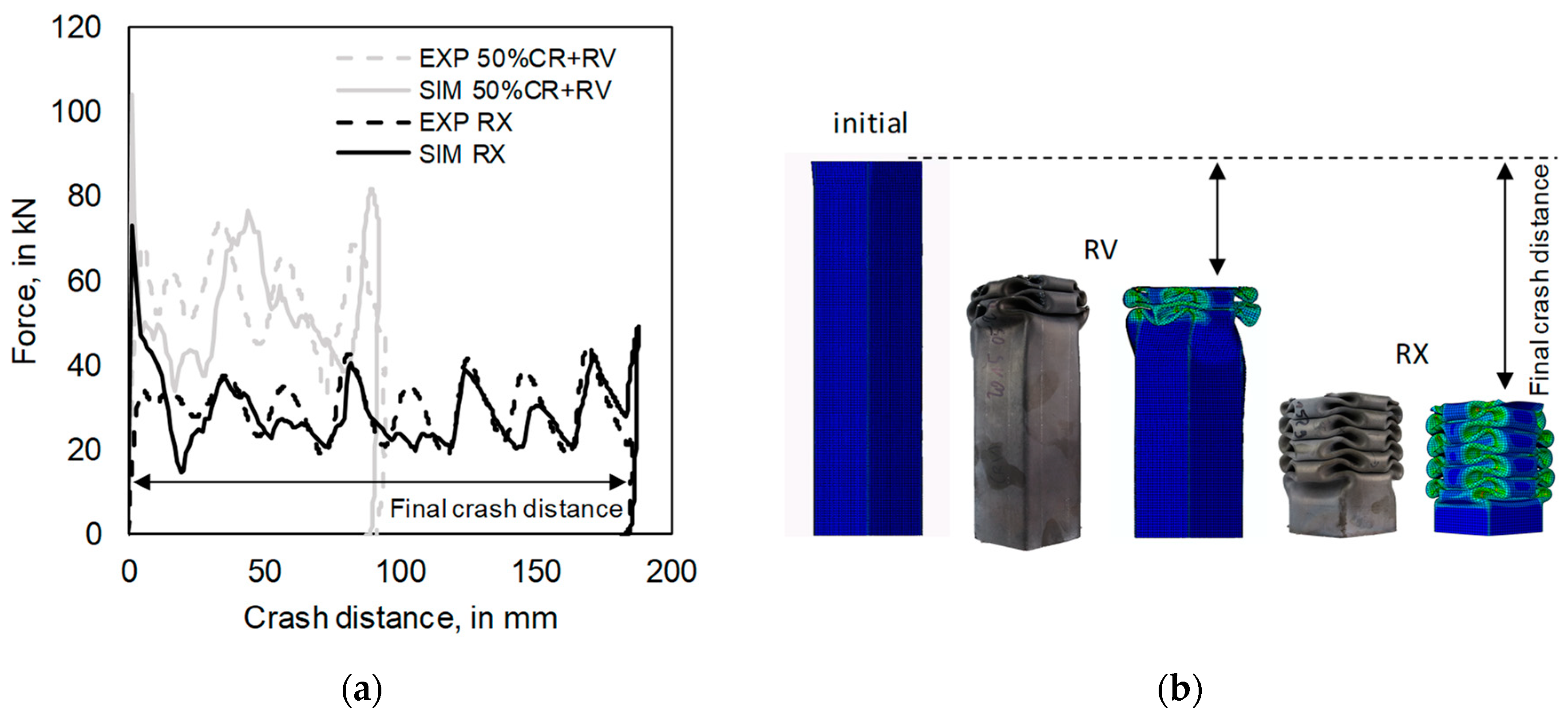
The comparison of force–distance curves of the material conditions RX and 50% CR + RV from drop tower simulations and experiments is shown in Figure 5a. Those two material conditions, crushed with the original geometry of 1 mm sheet thickness, were used to validate the FE model for the parameter study. The good agreement between simulation and experiment with respect to the final crash distance revealed the applied pre-strain and geometrical trigger in the FE model to be valid for the different material conditions. Figure 5b shows the final geometries of the crash boxes from the simulation with the final crash distance. For the RX condition, the whole crash box length was used for folding, using the full energy absorption potential of this crash box geometry, while for the RV condition half of the crash box length remained unfolded.
4.2. Influence of Material Condition on Behavior for Constant Sheet Thickness
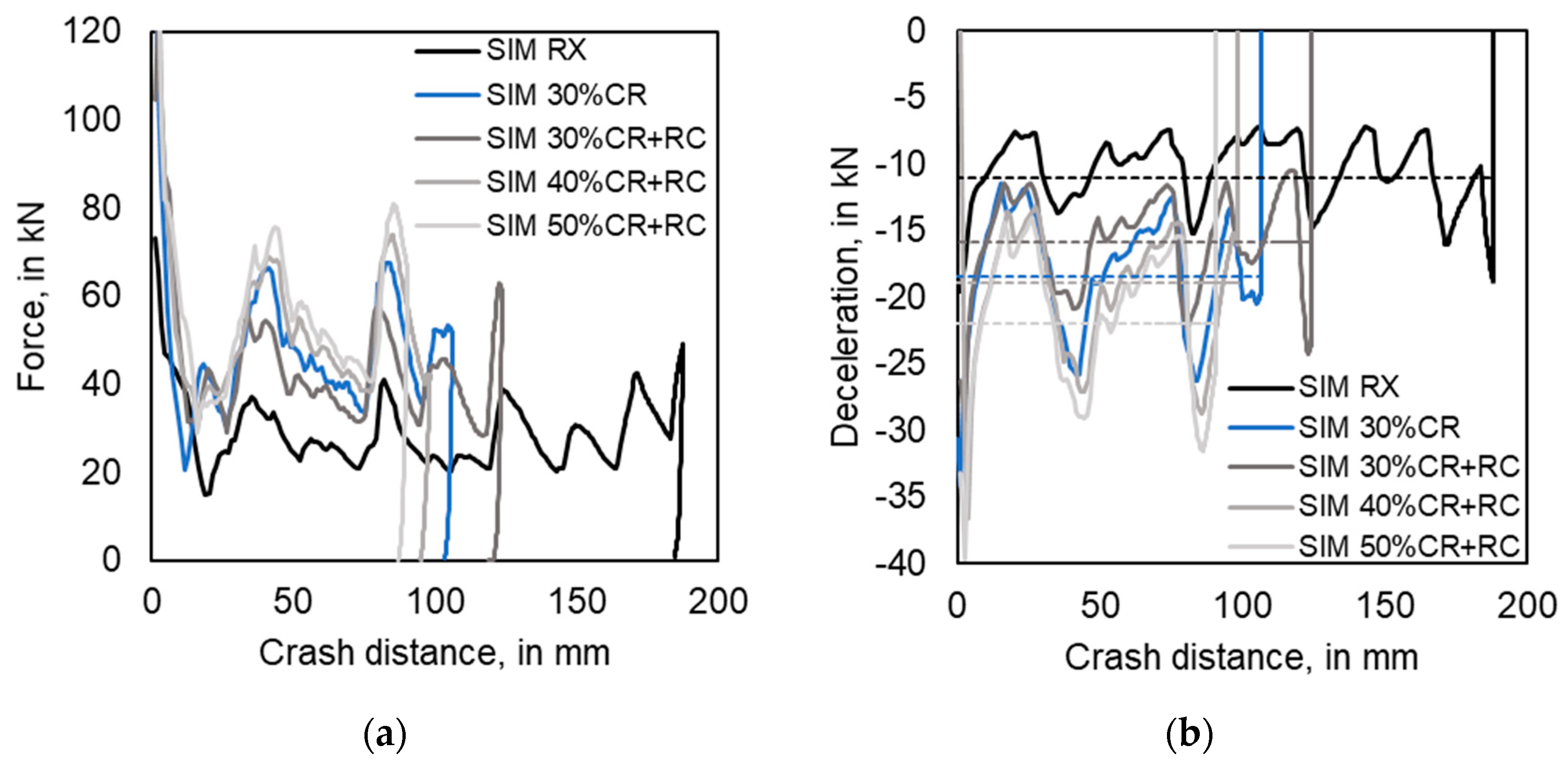
Using the experimental stress–strain curves from Figure 3a, the crash behavior of 30% CR and 40% CR + RV was simulated. The results are illustrated in Figure 6a,b. Due to recovery annealing of the 40% CR condition, the density of dislocations is reduced and strain hardening appears stronger than in the case of 30% CR. Using flow curves of both conditions in FE crash simulation of crash boxes with 1 mm sheet thickness shows that there is only a slight influence of hardening rate on the final crash distance and deceleration. The final crash distance is reduced and the mean deceleration is increased for the 40% CR + RV condition with the higher hardening rate.
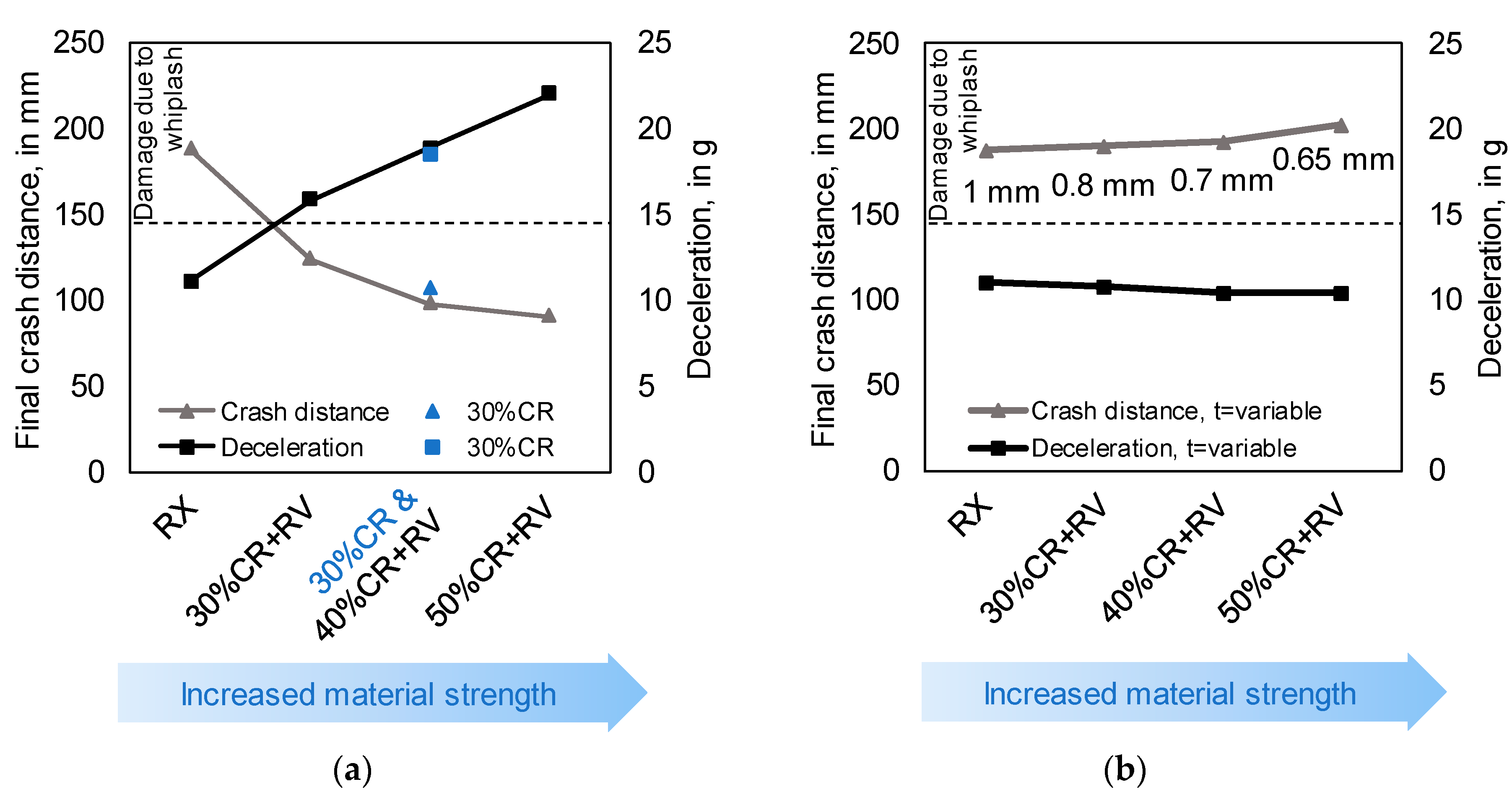
In addition to the hardening rate, the influence of the yield strength on the simulated crash behavior was investigated with different combinations of cold rolling degrees and recovery annealing. With increasing rolling degree, the material’s yield strength in Figure 3b increases, since the twin volume fraction increases with the increase of strain and remains stable during the recovery annealing [3]. In Figure 6a,b it is shown that with increasing strength of the material the final crash distance decreases and the mean deceleration increases. In Figure 7a both criteria are plotted for all material conditions including the limit of 15 g for deceleration. Only the RX condition satisfies the criterion of maximum deceleration. As a result, lightweight construction realized by reducing the necessary crash distance by increasing the strength of the material is not feasible due to the considered safety criterion, i.e., deceleration <15 g.
4.3. Optimization of Material and Sheet Thickness Combination for Crash Box
For the optimization of the combination of material condition and geometry for ideal crash behavior, the possible material conditions for crash boxes were reduced to the recovery-annealed conditions, as these conditions show a significant influence on final crash distance and enough strain reserves to guarantee a failure-free folding during the crash.
The sheet thickness of each material condition was reduced individually in order to enable the usage of the complete length of the crash box as well as reduced mean deceleration. In Figure 7b it is shown that with increasing material strength, the sheet thickness can be reduced to 0.8 mm for 30% CR + RV, 0.7 mm for 40% CR + RV, and 0.65 mm for 50% CR + RV, while using the complete length of the crash box as crash distance, similar to the RX condition, and while keeping the deceleration below 15 g.
The different material conditions with the according yield strength predicted by the CP simulations, the reduced sheet thickness, and the possible weight reduction are given in Table 2. A significant weight reduction of the crash boxes was achieved by reducing the sheet thickness of each material condition. For instance, the combination of 874 MPa yield strength of the 50% CR + RV condition and reduction of sheet thickness results in a weight reduction of 35%.
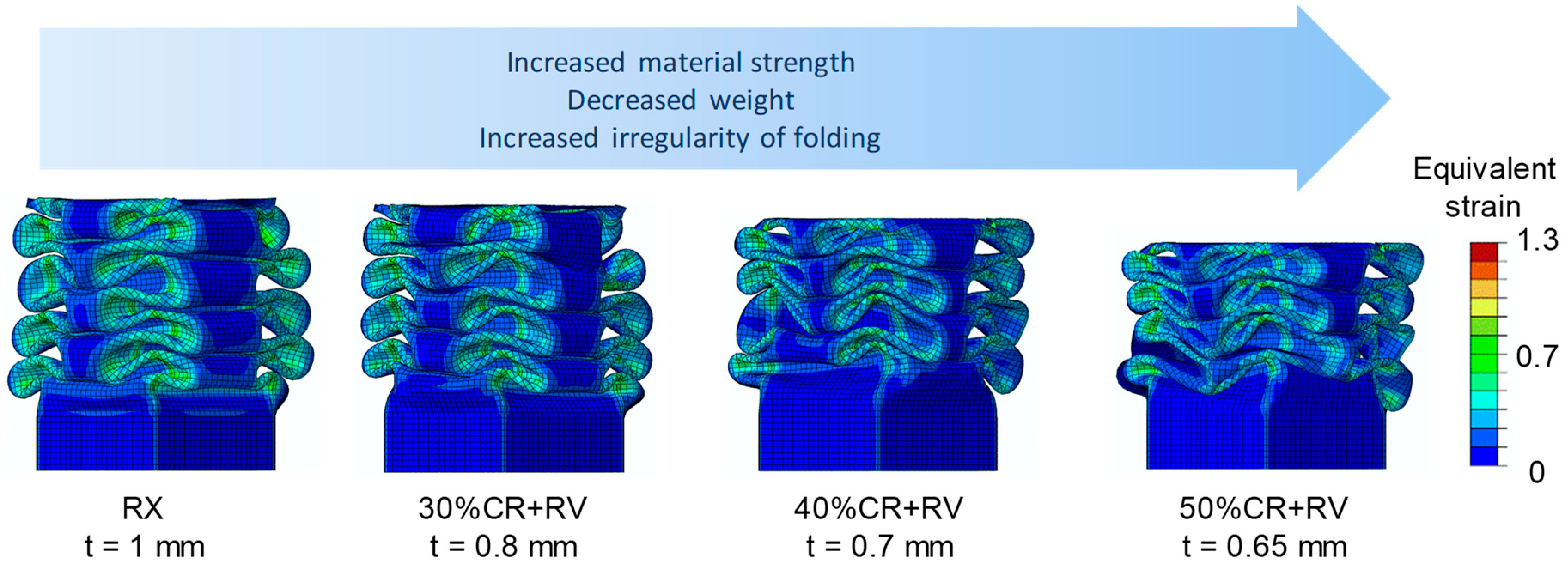
The final crash box geometries after drop tower simulation of the material conditions with reduced sheet thickness are shown in Figure 8. However, it was observed that with increasing material strength and decreasing sheet thickness, the pattern of the folds became more irregular.
5. Discussion
Different mechanical properties of the investigated X30MnAl23-1 HMnS could be designed by different procedures of cold rolling and heat treatment from Table 1. There is the possibility of adjusting the yield strength as well as the hardening rate. With increasing hardening rate, the final crash distance decreases but the influence of hardening rate on crash behavior is not very significant. Due to the dependence of the mechanical properties of the different material conditions on the process-specific microstructures, the range of different hardening rates combined with a similar yield strength are not independently adjustable. The yield strength of the different material conditions has a more pronounced influence on the crash behavior, as it significantly influences the final crash distance and therefore the deceleration. Moreover, the yield strength can be adjusted in a wider range by the degree of cold rolling.
Increasing the material strength by cold rolling, without consideration of crash box geometry, can successfully decrease the final crash distance and therefore contributes to the lightweight design by reducing the length of the crash box. However, as the FE simulation of a drop tower test showed, decreasing the final crash distance results in increased deceleration at the same time, which endangers the passenger safety due to increased risk of whiplash. The adaption of the sheet thickness as an additional degree of freedom in crash box geometry design can be used to optimize crash behavior for the different material conditions in order to fulfill all safety criteria. In this case, lightweight design is realized by reducing the sheet thickness, while using the original crash box length for folding. Another criterion, which has to be taken into account during optimization of material strength and sheet thickness, is the irregularity of the folding. To ensure regular folding for reproducible energy absorption, the sheet thickness can only be reduced within certain limits.
Based on tailored processing, the materials’ properties can be adjusted with respect to strength and strain-hardening potential. The strain-hardening behavior, which influences the crash behavior, can be described by the CP model. By applying the FE simulation, it is possible to predict the crash behavior in terms of the safety limit of 15 g deceleration and lightweight criteria, taking into account the influence of microstructure and box geometry. As a result, the experimental effort for crash box design could be reduced, since not every combination of material condition and sheet thickness has to be processed and tested in drop tower tests. With the correlation between processing and microstructure, the CP simulation can be used in further works to simulate material conditions, which have not been tested in tensile tests, to investigate the hardening behavior and increase the reduction of the experimental effort for the design of material conditions.
6. Conclusions
In this study, strain-hardening engineering was used to design an HMnS crash box by the application of a combination of multiscale characteristics. Considering safety and lightweight criteria, the ideal combination of material condition and sheet thickness was identified.
With the help of the simulation-based crash box design, the experimental effort could be reduced significantly and a reduction of weight up to 35% could be achieved by combining ideal material condition and sheet thickness.
Due to the multiscale simulation of CP simulation and FE simulation, the macroscopic crash behavior can be correlated with the microstructure, represented by the relation of dislocation density and twin density, and therefore with the processing of the materials.
Author Contributions
Conceptualization, A.Q., C.H., F.R. and M.T.; software, F.R.; methodology, A.Q. and M.M.; investigation, A.Q., and M.M.; writing—original draft preparation, A.Q.; writing—review and editing, M.T., C.H., F.R., M.M., and G.H.; visualization, A.Q.; supervision, M.T., and G.H.; project administration, G.H. and M.T.; funding acquisition, G.H.
Funding
This research was funded by the “Deutsche Forschungsgemeinschaft” (DFG) within the Sonderforschungsbereich (Collaborative Research Center) 761 “Steel–ab initio” with project number 29898171 within a collaboration of part project B2, B4, A7, and C6.
Conflicts of Interest
The authors declare no conflict of interest. The funders had no role in the design of the study; in the collection, analyses, or interpretation of data; in the writing of the manuscript, or in the decision to publish the results.
References
- De Cooman, B.C.; Kwon, O.; Chin, K.-G. State-of-the-knowledge on TWIP steel. Mater. Sci. Technol. 2012, 28, 513–527. [Google Scholar] [CrossRef]
- Bambach, M.; Conrads, L.; Daamen, M.; Güvençb, O.; Hirt, G. Enhancing the crashworthiness of high-manganese steel by strain-hardening engineering and tai-lored folding by local heat-treatment. Mater. Des. 2015, 110, 157–168. [Google Scholar] [CrossRef]
- Haase, C.; Barrales-Mora, L.A.; Molodov, D.A.; Roters, F.; Gottstein, G. Applying the texture analysis for optimizing thermomechanical treatment of high manganese twinning-induced plasticity steel. Acta Mater. 2014, 80, 327–340. [Google Scholar] [CrossRef]
- Haase, C.; Barrales-Mora, L.A.; Molodov, D.A.; Gottstein, G. Tailoring the Mechanical Properties of a Twinning-Induced Plasticity Steel by Retention of Deformation Twins During Heat Treatment. Metall. Mater. Trans. A 2013, 44, 4445–4449. [Google Scholar] [CrossRef]
- Haase, C.; Ingendahl, T.; Güvenc, O.; Bambach, M.; Bleck, W.; Molodova, D.A.; Barrales-Mora, L.A. On the applicability of recovery-annealed Twinning-Induced Plasticity steels: Potential and limitations. Mater. Sci. Eng. A 2015, 649, 74–84. [Google Scholar] [CrossRef]
- Güvenç, O.; Roters, F.; Hickel, T.; Bambach, M. ICME for Crashworthiness of TWIP Steels: From Ab Initio to the Crash Performance. JOM 2015, 67, 120–128. [Google Scholar] [CrossRef]
- Wong, S.L.; Madivala, M.; Prahl, U.; Roters, F.; Raabe, D. A crystal plasticity model for twinning- and transformation-induced plasticity. Acta Mater. 2016, 118, 140–151. [Google Scholar] [CrossRef]
- Schmidt, G. Grundlegendes zum Unfallmechanismus. In Die Beschleunigungsverletzung der Halswirbelsäule; Moorahrend, U.: Stuttgart, Germany, 1993; pp. 25–37. [Google Scholar]
- Roters, F.; Diehl, M.; Shanthraj, P.; Eisenlohr, P.; Reuber, C.; Wong, S.L.; Maitic, T.; Ebrahimid, A.; Hochrainere, T.; Fabritiusa, H.-O.; et al. DAMASK-The Düsseldorf Advanced Material Simulation Kit for modeling multi-physics crystal plasticity, thermal, and damage phenomena from the single crystal up to the component scale. Comput. Mater. Sci. 2019, 158, 420–478. [Google Scholar] [CrossRef]
- Diehl, M.; Groeber, M.; Haase, C.; Molodov, D.A.; Roters, F.; Raabe, D. Identifying Structure–Property Relationships Through DREAM.3D Representative Volume Elements and DAMASK Crystal Plasticity Simulations: An Integrated Computational Materials Engineering Approach. JOM 2017, 69, 848–855. [Google Scholar] [CrossRef]
- Haase, C.; Kühbach, M.; Barrales-Mora, L.A.; Wong, S.L.; Roters, F.; Molodova, D.A.; Gottstein, G. Recrystallization behavior of a high-manganese steel: Experiments and simulations. Acta Mater. 2015, 100, 155–168. [Google Scholar] [CrossRef]
- Gauss, W. Unfallrekonstruktion und biomechanische Begutachtung bei HWS-Verletzungen durch Heckaufprall. In Beschleunigungsverletzung der Halswirbelsäule; Graf, M., Grill, C., Eds.; Wedig, H.-D.: Darmstadt, Germany, 2009; pp. 78–91. [Google Scholar]
Figure 1.
Multiscale simulation chain with ab initio calculation of stacking fault energy (SFE), crystal plasticity simulation for hardening behavior and finite element (FE) simulation for crash behavior. The references in the figure indicate the sources used for data acquisition.
Figure 1.
Multiscale simulation chain with ab initio calculation of stacking fault energy (SFE), crystal plasticity simulation for hardening behavior and finite element (FE) simulation for crash behavior. The references in the figure indicate the sources used for data acquisition.

Figure 2.
Schematic overview of the process chain and comparison of experimental and simulation-based design of material conditions for high manganese crash boxes.
Figure 2.
Schematic overview of the process chain and comparison of experimental and simulation-based design of material conditions for high manganese crash boxes.

Figure 3.
(a) True stress–strain curves of 30% CR and 40% CR + RV from experiments with similar yield strength but different hardening behavior with original data from tensile test (orig) and corrected data with offset (corr); (b) True stress–strain curves from tensile tests (EXP) and crystal plasticity (CP) simulation (SIM) of recovery annealed (RV) and recrystallized (RX) material conditions.

Figure 4.
(a) Crash box geometry with boundary conditions of the FE simulation; (b) Hexagonal profile in mm with marked plane where the half hexagons were laser welded.
Figure 4.
(a) Crash box geometry with boundary conditions of the FE simulation; (b) Hexagonal profile in mm with marked plane where the half hexagons were laser welded.

Figure 5.
(a) Experimental and simulated force–distance curves from drop tower tests with sheet thickness t = 1 mm of the RX and 50% CR + RV conditions; (b) Geometries of the crash boxes before (initial) and after simulated and experimental drop tower tests of the RX and 50% CR + RV conditions.
Figure 5.
(a) Experimental and simulated force–distance curves from drop tower tests with sheet thickness t = 1 mm of the RX and 50% CR + RV conditions; (b) Geometries of the crash boxes before (initial) and after simulated and experimental drop tower tests of the RX and 50% CR + RV conditions.

Figure 6.
(a) Simulated force–distance curves of drop tower tests with sheet thickness t = 1 mm for different material conditions; (b) Simulated deceleration during crash for the different material conditions with mean deceleration (dashed lines).
Figure 6.
(a) Simulated force–distance curves of drop tower tests with sheet thickness t = 1 mm for different material conditions; (b) Simulated deceleration during crash for the different material conditions with mean deceleration (dashed lines).

Figure 7.
(a) Final crash distance and mean deceleration from FE parameter study for t = 1 mm for all material conditions; (b) Final crash distance and mean deceleration from FE parameter study for individual t for each material condition.
Figure 7.
(a) Final crash distance and mean deceleration from FE parameter study for t = 1 mm for all material conditions; (b) Final crash distance and mean deceleration from FE parameter study for individual t for each material condition.

Figure 8.
Final crash box geometry after crash simulation for individual t for each material condition.
Figure 8.
Final crash box geometry after crash simulation for individual t for each material condition.


Table 1.
Cold rolling degree and heat treatment parameters for recovery annealing and recrystallization. CR: cold rolled; RV: recovery; RX: recrystallized.
Table 1.
Cold rolling degree and heat treatment parameters for recovery annealing and recrystallization. CR: cold rolled; RV: recovery; RX: recrystallized.
| Material Condition | Rolling DEGREE (%) | Annealing Temperature (°C) | Annealing Time (min) |
|---|---|---|---|
| 30% CR + RV | 30 | 630 | 10 |
| 40% CR + RV | 40 | 550 | 60 |
| 50% CR + RV | 50 | 550 | 30 |
| 50% CR + RX | 50 | 700 | 10 |
Table 2.
Yield strength of simulated flow curves of different material conditions, individual sheet thickness and weight reduction of different material conditions.
Table 2.
Yield strength of simulated flow curves of different material conditions, individual sheet thickness and weight reduction of different material conditions.
| Material Condition | Yield Strength SIM (MPa) | Sheet Thickness (mm) | Weight Reduction (%) |
|---|---|---|---|
| 50% CR + RX | 256 | 1.00 | Reference |
| 30% CR + RV | 640 | 0.80 | 20 |
| 40% CR + RV | 819 | 0.70 | 30 |
| 50% CR + RV | 874 | 0.65 | 35 |
© 2019 by the authors. Licensee MDPI, Basel, Switzerland. This article is an open access article distributed under the terms and conditions of the Creative Commons Attribution (CC BY) license (http://creativecommons.org/licenses/by/4.0/).
Share and Cite
MDPI and ACS Style
Quadfasel, A.; Teller, M.; Madivala, M.; Haase, C.; Roters, F.; Hirt, G. Computer-Aided Material Design for Crash Boxes Made of High Manganese Steels. Metals 2019, 9, 772. https://doi.org/10.3390/met9070772
AMA Style
Quadfasel A, Teller M, Madivala M, Haase C, Roters F, Hirt G. Computer-Aided Material Design for Crash Boxes Made of High Manganese Steels. Metals. 2019; 9(7):772. https://doi.org/10.3390/met9070772
Chicago/Turabian StyleQuadfasel, Angela, Marco Teller, Manjunatha Madivala, Christian Haase, Franz Roters, and Gerhard Hirt. 2019. "Computer-Aided Material Design for Crash Boxes Made of High Manganese Steels" Metals 9, no. 7: 772. https://doi.org/10.3390/met9070772
Note that from the first issue of 2016, this journal uses article numbers instead of page numbers. See further details here.