Article

Aging Phenomena during In-Service Creep Exposure of Heat-Resistant Steels

1
Department of Mechanical Engineering, Khalifa University, Abu Dhabi 127788, UAE
2
Department of Mechanical Engineering, University of Thessaly, Volos 38334, Greece
3
Center for Catalysis and Separations, Khalifa University, Abu Dhabi 127788, UAE
*
Author to whom correspondence should be addressed.
Metals 2019, 9(7), 800; https://doi.org/10.3390/met9070800
Submission received: 17 June 2019 / Revised: 11 July 2019 / Accepted: 17 July 2019 / Published: 19 July 2019
(This article belongs to the Special Issue Failure Mechanisms in Alloys)

Abstract

:
An investigation of aging phenomena during creep exposure has been conducted for HP-Nb cast reformer tubes for several exposure conditions. Aging was manifested by carbide precipitation, carbide coarsening, and carbide transformation. The transformation of primary M7C3 to the more stable M23C6 carbide takes place at high exposure temperature (910 °C and above). The primary MC carbides transform to the Ni-Nb silicide or G-phase during creep exposure. The presence of Ti in the steel prevented the transformation of MC carbides to the G-phase. Morphological changes like needle to globular transitions, rounding of carbide edges, and carbide coarsening take place during creep exposure. The room-temperature tensile elongation and ultimate tensile strength are significantly reduced during creep exposure. The above aging phenomena are precursors to creep damage.

1. Introduction

Catalytic reforming is routinely employed in oil refineries for the production of petroleum byproducts. The process takes place in tubes suspended in a furnace at a high temperature. The tubes are fed with hydrocarbon, mostly methane, and steam mixture in the presence of a catalyst according to the reaction network:
C n H m + n H 2 O n C O + ( m 2 + n ) H 2 ,
C O + H 2 O C O 2 + H 2 .
The first is the steam reforming reaction, which, for the case of methane, is strongly endothermic (ΔHr = 206 KJ/mol) and takes place at a high temperature of the order of 900 °C. The second is the water-gas shift reaction and is mildly exothermic (ΔHr = −41 KJ/mol). The internal pressure in the tubes generates stresses, causing creep of the tube material. However, prior to creep damage, several aging phenomena take place, which gradually changes the microstructure of the material. The reformer furnace tubes are centrifugally cast and are manufactured from heat-resistant steels, containing Ni and Cr. The current state-of-the-art is to use modified HP-alloys (25Cr-35Ni), with Nb and/or Ti additions. Niobium is added for the precipitation of NbC, which due to its thermal stability contributes to an increased creep resistance [1,2]. Centrifugal casting results in austenitic dendritic grains oriented in the radial direction from the inside diameter (ID) towards the outside diameter (OD) of the tube. The material is strengthened by a network of primary interdendritic carbides. The design life of these tubes is 100,000 h (11.4 years) according to API recommended practice [3]. Premature failures of reformer tubes are frequently observed and are caused by various mechanisms such as creep, carburization, and thermal shock. Evaluation of creep damage in reformer tubes has been reported by several investigators, either after creep testing [2,4,5], after a certain operational time [6,7,8,9,10], or after premature tube rupture [11,12]. In addition, specific studies of microstructural evolution after long-term aging at high temperatures have been performed [13,14,15]. The present work contributes to the study of the evolution of carbides and other intermetallic compounds with aging during creep exposure. These phenomena lead to a decrease of ductility and may lead to cracking from thermal stresses during shut-down and start-up operations or during weld repairs.
It is important to note that most of the published data are concerned with studies involving laboratory creep exposure. Results based on specimens taken from real service are rather rare. It is not common to retrieve specimens during a shut-down of a reformer furnace. Therefore, the value of the present work is that the analysis was based entirely on specimens of reformer tubes extracted after a certain operational period, before the end of operational life, and for different temperatures.

2. Materials and Methods

Sections of reformer tubes with an internal diameter of 103 mm and a thickness of 15 mm were retrieved from an oil refinery after 11 years of service. These sections correspond to isothermal operation at three different temperatures 830, 880, and 910 °C and are named as conditions L, M, and H respectively. Another section came from a tube that operated for 8 years at 910 °C and was then nipped for the remaining 3 years, during which the temperature was 950 °C. This section corresponds to condition X. The material of these sections is an HP25Cr-35Ni alloy with Nb addition (HP-Nb steel). The creep strain was estimated by measurements of the outer diameter of the tubes to be of the order of 0.2%. It was also possible to retrieve a section of a reformer tube from another refinery after 5 years of service at 910 °C. This condition is named H5 and the chemical composition of H5 is similar to the previous one with the most important difference being the addition of Ti. This tube sampling enabled the study of the effect of temperature on aging phenomena by comparing sections L, M, H, and X. At the same time, the effect of time and Ti addition could also be performed by comparing sections H and H5. Chemical analysis of the tube materials was performed by optical emission spectrometry. The composition of the alloys and creep exposure conditions are shown in Table 1.
Characterization of microstructure, including aging phenomena, carbide transformation, and carbide morphology was performed by means of light optical metallography (LOM) and scanning electron microscopy equipped with an energy dispersive X-ray analysis system (EDX). Metallography was performed on thickness specimens from all tube sections. Specimen preparation for metallography involved cutting with a Struers Labotom-3 machine (Struers, Ballerup, Denmark), grinding with SiC papers with 240, 400, 800, 1200, and 2400 grit, polishing with 6, 3, and 1 μm diamond paste and finishing with colloidal silica suspension of 0.04 μm. The etching was performed by swabbing with Kalling’s reagent (CuCl2 in a mixture of hydrochloric acid and ethanol). Optical metallography was performed on an Olympus inverted microscope (Olympus, Tokyo, Japan) at magnifications 50–1000×. Scanning electron microscopy (SEM) was performed on etched specimens on a field emission JEOL JSM 7610F (JEOL, Tokyo, Japan) and Quanta 3D microscopes (ThermoFisher Scientific, Hillsboro, OR, USA)equipped with an energy dispersive X-ray analysis (EDX) detector (Oxford Instruments, Abingdon, UK). Imaging was performed with secondary electron mode (SE) and in certain cases with backscattered electron (BSE) mode. Room temperature uniaxial tensile testing was performed according to ISO 6892 specification [16].

3. Results

3.1. Tensile Properties

Room temperature tensile testing results are shown in Figure 1. The results indicate a decrease of the ultimate tensile strength (UTS) and a considerable reduction in tensile elongation (strain to failure) with exposure temperature, as a result of aging. Condition H5 also exhibits considerable reduction in elongation, however the elongation is higher than the elongation of condition H. Similar reductions in tensile ductility have been reported by Pan et al. [11] after 36,000 h at 910 °C (4.12 years), and Monobe et al. [13] after exposure for 200 h at 720–780 °C. The aging phenomena and carbide transformations are discussed in the following section.

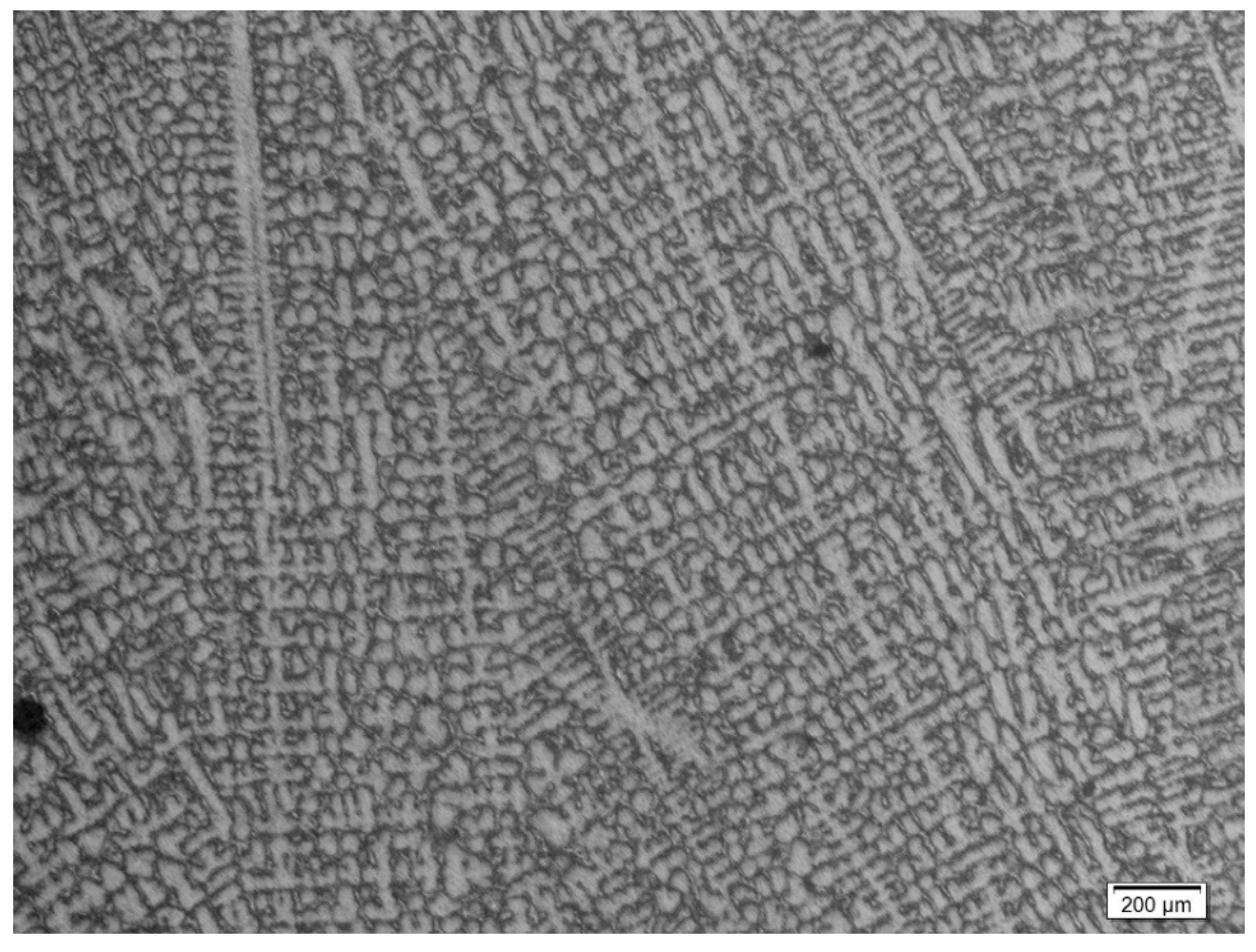
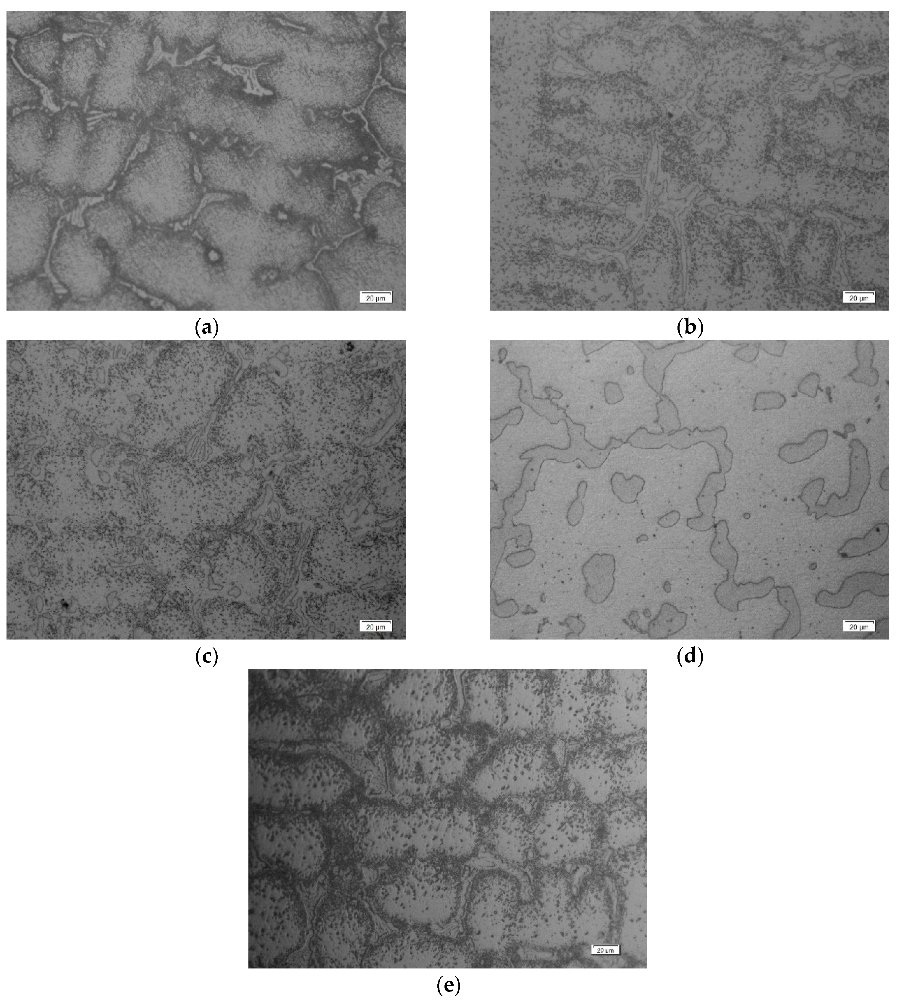
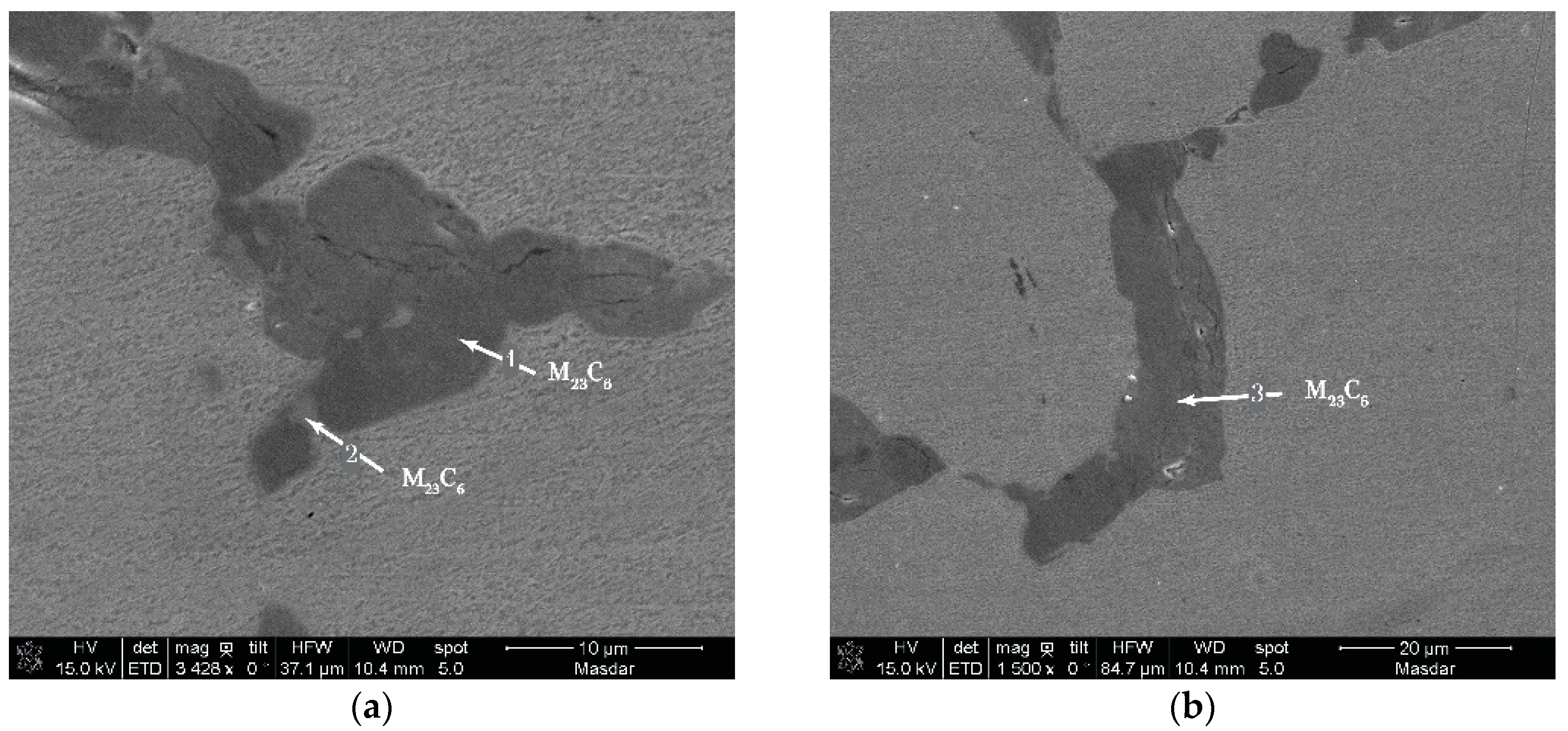
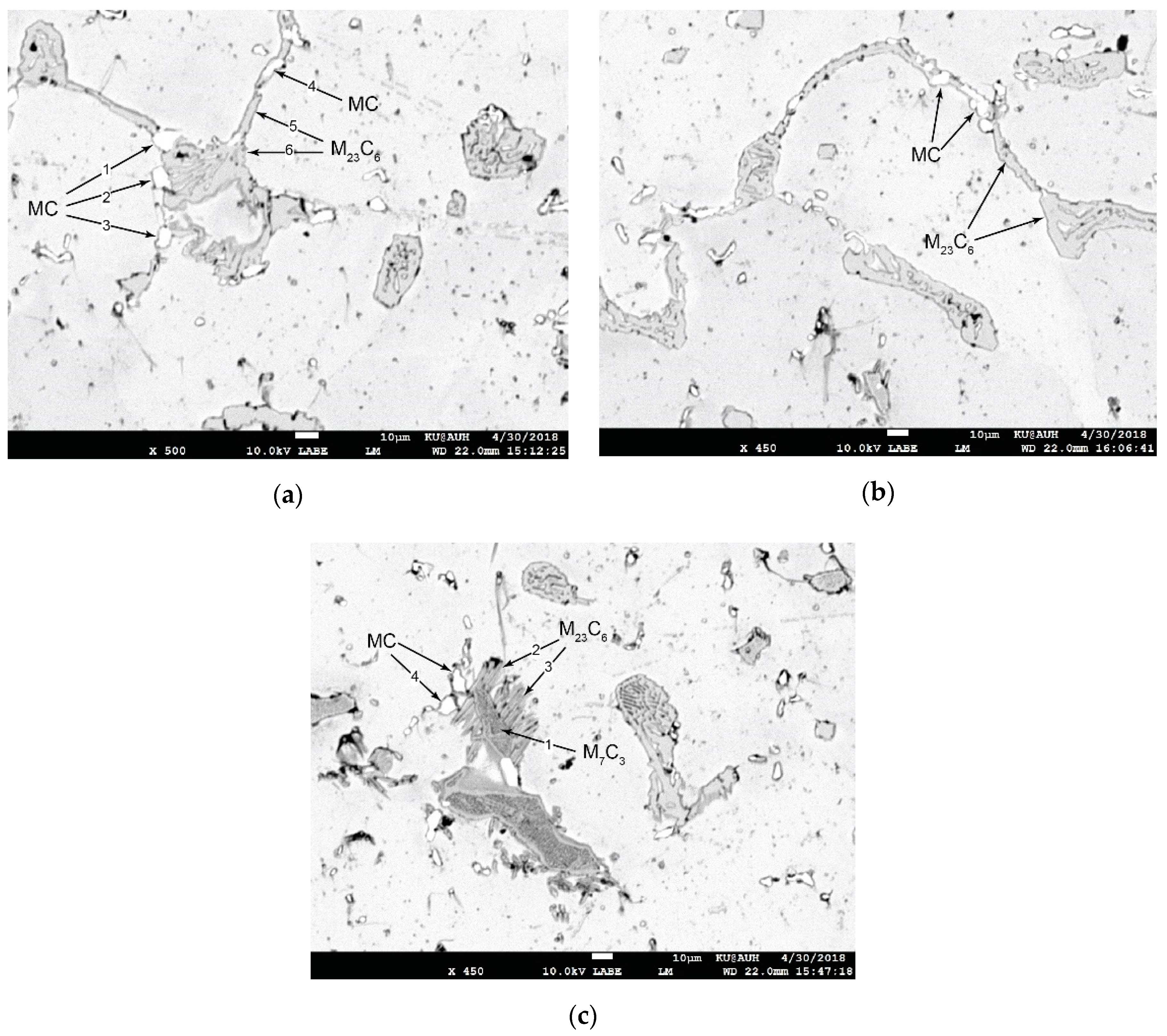
3.2. Microstructure Analysis

Carbides and other phases have been identified in this work with SEM/EDX analysis. Carbides were identified by the M:C ratio and the G-phase by the Ni:Nb:Si ratio. It should be noted that the EDX composition analysis of carbides is semi-quantitative, since it depends on the spot size relative to the carbide size. In order to avoid matrix contribution to the EDX spectrum, a low voltage was used during the EDX analysis. The analysis, therefore, provides a valid indication of the nature of the carbides.
The microstructure of the alloy consists of an austenitic matrix, forming dendrites, and a network of primary carbides. The dendrite length varies from 0.3 to 6.5 mm with an average length of 1.4 mm as depicted in Figure 2. The dendrites are oriented in the radial direction from the inner diameter (ID) to the outer diameter (OD) of the tube. Some dendrites are very long with a length being a significant fraction of the tube thickness. In the as-cast condition, the austenite matrix is free of precipitates, as reported by Alvino et al. [6].
The carbides are located either in interdendritic or intradendritic regions and are either Cr-rich of M7C3 or M23C6 type and Nb-rich MC carbides. M23C6 are mostly grain boundary film-like carbides. M7C3 carbides exhibit a “Chinese script” morphology. Long-term exposure resulted in aging, manifested by the secondary precipitation in the austenitic matrix and coarsening of carbides. Such intragranular precipitation and carbide coarsening have also been observed by Attarian et al. [4] in HP-Nb steel after aging at 982 °C for 100 h. The results are presented for each exposure condition below.
Condition L (830 °C/11y): The microstructure is depicted in Figure 3a, consisting of M7C3 carbides. Identification of M7C3 carbides was based on SEM/EDX analysis of Figure 4. The numbers in Figure 4 correspond to EDX composition analysis, which is presented in Table 2. These carbides exhibit a “Chinese script” morphology. In addition to this morphology, M7C3 carbides appear with a needle morphology (Figure 3a and Figure 4b).
Condition M (880 °C/11y): The microstructure is depicted in Figure 3b. The “Chinese script” morphology of M7C3 carbides is preserved with considerable rounding of edges. However, the needle-shaped M7C3 carbides have undergone a morphological transformation and exhibit a globular shape. This morphological transformation has been observed in directionally solidified HP-Ni steel [4]. The NbC carbides, originally present in the as-cast microstructure, transformed to a Ni-Nb silicide, the G-phase, with nominal composition Ni16Nb7Si6, as depicted in Figure 5a,b. The numbers in Figure 5 correspond to EDX composition analysis, which is presented in Table 2. This transformation has been observed, in Ti-free alloys, by Pan et al. [11] and by Soares et al. [17]. The G-phase is hard and brittle and, therefore, prone to cavity formation when the material is subjected to temperature excursions [11,17]. However, it should be noted that no cavities formed on the G-phase were detected at this operating condition. In addition, no M23C6 carbides were detected in condition M, indicating that the transformation of M7C3 to M23C6 carbides had not taken place.
Condition H (910 °C/11y): The microstructure is depicted in Figure 3c. Most of the M7C3 carbides have transformed into the more stable M23C6 carbides as shown in Figure 6a,b. The numbers in Figure 6 correspond to EDX composition analysis, which is presented in Table 2. Significant coarsening of the M23C6 carbides has also taken place driven by the reduction in interfacial energy.
Condition X (910 °C/8y + 950 °C/3y): The microstructure is depicted in Figure 3d. All carbides are of the M23C6 type and significant coarsening has taken place due to exposure at high temperature (950 °C). Nb has also been incorporated in the M23C6 carbides as indicated in Figure 7a,b. The numbers in Figure 7 correspond to EDX composition analysis, which is presented in Table 2.
Condition H5 (910 °C/5y): It is noted that the H5 condition concerns the material containing Ti. The optical micrograph of the microstructure is depicted in Figure 3e. The microstructure of H5 material was investigated with SEM operating in the SE and BSE modes. Typical microstructures are depicted in Figure 8. The numbers in Figure 8 correspond to EDX composition analysis, which is presented in Table 2. MC carbides (Nb-rich), appear white, while M23C6, Cr-rich carbides appear dark grey in the BSE images due to the difference in atomic number between Nb and Cr. SEM-BSE imaging has been used by other researchers for carbide identification in cast heat-resistant steels [6,15]. The results indicate that MC carbides contain Ti, which according to Swaminathan et al. [18], stabilizes the MC carbide against transformation to the G-phase. This explains the fact that no G-phase was detected in the H5 material. Most probably, the transformation of the primary M7C3 carbides to M23C6 is partial, contrary to the H condition where the transformation was complete. This partial transformation is depicted in Figure 8c with the associated EDX analysis of carbides in Table 2.

4. Discussion

Creep resistance in cast steel reformer tubes depends, among other factors, on the thermal stability of the carbides. During operation at high temperatures, the carbides undergo phase changes as well as morphological changes, which degrade the creep resistance of the material. Phase changes involve the transformation of primary M7C3 to the more thermodynamically stable, at those temperatures of operation, M23C6. Morphological changes involve the coarsening of carbides driven by the reduction of interfacial energy [4,6]. Finally, an aging reaction, manifested as secondary precipitation of carbides within the austenitic matrix takes place during creep exposure [6]. In the present work, the transformation of M7C3 to the more stable M23C6 was observed to take place only at 910 °C and above for 11 years of operation period (conditions H and X). In these conditions the transformation is complete. In an intermediate operation period of five years (condition H5), the M7C3 to M23C6 transformation is partial. Significant coarsening of the carbides takes place at high temperatures (conditions H and X) while at lower temperatures the changes are morphological, i.e., the rounding of edges or the change from needle-shaped carbides to a globular morphology (condition M). Another interesting aging phenomenon during creep exposure is the transformation of the primary MC carbides to the Ni-Nb silicide of G-phase manifested at intermediate temperatures (condition M). At higher temperatures, the G-phase dissolves and the Nb is incorporated in the M23C6 carbide. Similar observations regarding the type and morphologies of various carbides in creep-exposed HP-Nb steels have been reported by Allesio et al. [2] and Almeida et al. [15]. Finally, the presence of NbC carbides and the corresponding absence of G-phase in the H5 condition in the Ti-containing material validated previous observations that Ti stabilizes the MC carbide and acts against the transformation of the MC carbides to the G-phase [11,17]. As a result of aging the room temperature tensile elongation (strain to failure) is reduced considerably. The reduction is higher the higher the temperature of exposure. This reduced ductility makes the material prone to cracking due to expansions and contractions, which take place during shut-down/start-up of the reformer furnace.

5. Conclusions

An investigation of aging phenomena during creep has been conducted for HP-Nb cast reformer tubes. Based on the results presented above, the following conclusions can be drawn:
Aging was manifested by carbide precipitation, carbide coarsening and transformation from M7C3 to M23C6 carbides.
The MC carbides transform to the G-phase during creep exposure making the material more prone to cavity formation. The presence of Ti in the steel of condition H5 prevented the transformation of MC carbides to the G-phase.
Morphological changes occur as needle to globular transitions, rounding of edges, and carbide coarsening take place during creep exposure.
As a result of aging phenomena, the room-temperature tensile ductility is reduced, making the material prone to cracking during shut-down/start-up operations.

Author Contributions

Conceptualization, G.N.H.; methodology, K.P.; mechanical testing H.K. and A.D.Z.; metallography S.I.A., P.C., H.M. and S.J.; SEM/EDX, K.P.; paper preparation and editing, G.N.H.

Funding

This research received no external funding.

Acknowledgments

The assistance of Roba Khaled Saab of KU with SEM/EDX is greatly appreciated.

Conflicts of Interest

The authors declare no conflict of interest.

References

  1. Barbabela, G.D.; de Almeida, L.H.; da Silveira, T.L.; Le May, I. Role of Nb in modifying the microstructure of heat-resistant cast HP steel. Mater. Charact. 1991, 26, 193–197. [Google Scholar] [CrossRef]
  2. Alessio, D.; Gonzalez, G.; Pirrone, V.F.; Iurman, L.; Moro, L. Variation of Creep Properties in HP Steel by Influence of Temperature. Proc. Mater. Sci. 2012, 1, 104–109. [Google Scholar] [CrossRef] [Green Version]
  3. API. Calculation of Heater Tube Thickness in Petroleum Refineries: API Recommended Practice 530, 3rd ed.; API: Washington, DC, USA, 1988. [Google Scholar]
  4. Attarian, M.; Taheri, A.K. Microstructural evolution in creep aged of directionally solidified heat resistant HP-Nb steel alloyed with tungsten and nitrogen. Mater. Sci. Eng. A 2016, 659, 104–118. [Google Scholar] [CrossRef]
  5. Ray, A.K.; Roy, N.; Raj, A.; Roy, B.N. Structural integrity of service exposed primary reformer tube in a petrochemical industry. Int. J. Pres. Ves. Pip. 2016, 137, 46–57. [Google Scholar] [CrossRef]
  6. Alvino, A.; Lega, D.; Giacobbe, F.; Mazzocchi, V.; Rinaldi, A. Damage characterization in two reformer heater tubes after nearly 10 years of service at different operative and maintenance conditions. Eng. Fail. Anal. 2010, 17, 1526–1541. [Google Scholar] [CrossRef]
  7. Bonaccorsi, L.; Guglielmino, E.; Pino, R.; Servetto, C.; Sili, A. Damage analysis in Fe–Cr–Ni centrifugally cast alloy tubes for reforming furnaces. Eng. Fail. Anal. 2014, 36, 65–74. [Google Scholar] [CrossRef]
  8. Gong, J.-M.; Tu, S.-T.; Yoon, K.-B. Damage assessment and maintenance strategy ofhydrogen reformer furnace tubes. Eng. Fail. Anal. 1999, 6, 143–153. [Google Scholar] [CrossRef]
  9. Lee, J.H.; Yang, W.J.; Yoo, W.D.; Cho, K.S. Microstructural and mechanical property changes in HK40 reformer tubes after long term use. Eng. Fail. Anal. 2009, 16, 1883–1888. [Google Scholar] [CrossRef]
  10. Ray, A.K.; Kumar, S.; Krishna, G.; Gunjan, M.; Goswami, B.; Bose, S.C. Microstructural studies and remnant life assessment of eleven years service exposed reformer tube. Mater. Sci. Eng. A 2011, 529, 102–112. [Google Scholar] [CrossRef]
  11. Pan, J.-H.; Chen, Z.; Fan, Z.-C.; Wu, Y.-C. An experimental investigation on manifold failure and material deterioration. Int. J. Pres. Ves. Pip. 2018, 162, 1–10. [Google Scholar] [CrossRef]
  12. Ray, A.K.; Sinha, S.K.; Tiwari, Y.N.; Swaminathan, J.; Das, G.; Chaudhuri, S.; Singh, R. Analysis of failed reformer tubes. Eng. Fail. Anal. 2003, 10, 351–362. [Google Scholar] [CrossRef]
  13. Monobe, L.S.; Schön, C.G. Characterization of the cold ductility degradation after aging in centrifugally cast 20Cr32Ni+Nb alloy tube. Int. J. Pres. Ves. Pip. 2009, 86, 207–210. [Google Scholar] [CrossRef]
  14. Kenik, E.A.; Maziasz, P.J.; Swindeman, R.W.; Cervenka, J.; May, D. Structure and phase stability in a cast modified-HP austenite after long-term ageing. Scr. Mater. 2003, 49, 117–122. [Google Scholar] [CrossRef]
  15. De Almeida, L.H.; Ribeiro, A.F.; Le May, I. Microstructural characterization of modified 25Cr–35Ni centrifugally cast steel furnace tubes. Mater. Charact. 2002, 49, 219–229. [Google Scholar] [CrossRef]
  16. ISO 6892-1:2016. Metallic Materials—Tensile testing—Part 1: Method of Test at Room; International Organization for Standardization: Geneva, Switzerland, 2016.
  17. De Almeida Soares, G.D.; de Almeida, L.H.; da Silveira, T.L.; Le May, I. Niobium additions in HP heat-resistant cast stainless steels. Mater. Charact. 1992, 29, 387–396. [Google Scholar] [CrossRef]
  18. Swaminathan, J.; Guguloth, K.; Gunjan, M.; Roy, P.; Ghosh, R. Failure analysis and remaining life assessment of service exposed primary reformer heater tubes. Eng. Fail. Anal. 2008, 15, 311–331. [Google Scholar] [CrossRef]
Figure 1. Room-temperature tensile properties vs. creep exposure conditions.
Metals 09 00800 g001
Figure 2. Microstructure of HP-Nb steel with austenite dendritic structure and carbide network in the interdendritic regions.
Metals 09 00800 g002
Figure 3. Microstructure revealed by metallography: (a) Condition L, (b) condition M, (c) condition H, (d) condition X, and (e) condition H5.
Metals 09 00800 g003
Figure 4. SEM image depicting M7C3 carbides in condition L. (a) “Chinese script” morphology; (b) needle morphology. Numbers indicate EDX composition analysis in Table 2.
Metals 09 00800 g004
Figure 5. SEM images, (a,b), depicting M7C3 carbides and G-phase in condition M. Numbers indicate EDX composition analysis in Table 2.
Metals 09 00800 g005
Figure 6. SEM images, (a,b), depicting M23C6 carbides in condition H. Numbers indicate EDX composition analysis in Table 2.
Metals 09 00800 g006
Figure 7. SEM images, (a,b), depicting coarse M23C6 carbides in condition X. Numbers indicate EDX composition analysis in Table 2.
Metals 09 00800 g007
Figure 8. SEM-BSE images depicting: (a,b) MC and M23C6 carbides in condition H5; (c) transformation of M7C3 to M23C6 carbide after creep exposure of 5 years. Numbers correspond to EDX composition analysis in Table 2.
Metals 09 00800 g008
Table 1. Composition (wt%) of the alloys and creep exposure conditions.
CodeT (°C)t (y)CSiMnPSCrNiNbMoTiFe
L830110.4920.800.010.0125.733.60.930.18-B
M88011
H91011
X910/9508/3
H591050.411.61.00.020.012434.70.960.070.2B
Table 2. EDX analysis (at%).
ConditionsCrNiFeNbTiSiCMM:CPhases
Figure 4 (L)154.3410---31.668.32.16M7C3
255.848.5---31.668.32.16M7C3
3 matrix23.829.638.50.30.5-4---
4 needles19.421.522.2---31.863.11.98M7C3
Figure 5 (M)162.73.727.2---25.473.622.87M7C3
2-46-16.4-21.8---G
3-54.17-19.1-26.7---G
459.236---3268.22.13M7C3
5-55-19.6-26---G
Figure 6 (H)16847---21793.76M23C6
267.53.85.5---23.376.83.30M23C6
367.154.25.9---22.877.253.38M23C6
467.14.35.8---22.777.23.4M23C6
Figure 7 (X)1593115--22783.54M23C6
259.23.7104.3--22.677.23.41M23C6
346.720.13.94.6--21.575.33.50M23C6
Figure 8a (H5)1---52.21.7-46.153.91.17MC
2---502.7-47.352.71.11MC
3---51.32.5-46.253.81.16MC
4---41.45-53.646.40.86MC
553.47.816.8---22783.54M23C6
6594.715.3---21793.76M23C6
matrix25.433.434.7---5.2---
matrix25.933.234.6---5---
Figure 8c (H5)157.41.47.6---33.666.41.97M7C3
228.122.229.2---20.579.53.87M23C6
333.119.625.3---21.3783.66M23C6
4---41.32.7-56440.78MC

