Experimental Study and Numerical Simulation of the Intermittent Feed High-Speed Grinding of TC4 Titanium Alloy

1
Intelligent Manufacturing Institute of HNUST, Hunan University of Science and Technology, Xiangtan 411201, China
2
Hunan Provincial Key Laboratory of High Efficiency and Precision Machining of Difficult-to-Cut Material, Hunan University of Science and Technology, Xiangtan 411201, China
*
Author to whom correspondence should be addressed.
Metals 2019, 9(7), 802; https://doi.org/10.3390/met9070802
Submission received: 23 June 2019
/
Revised: 10 July 2019
/
Accepted: 17 July 2019
/
Published: 21 July 2019
(This article belongs to the Special Issue Advanced Manufacturing Technology in the Automotive Industry)
Abstract
:This paper proposes intermittent feed high-speed grinding, which shows considerable advantages in terms of reducing grinding temperature, relieving grinding wheel blockage and improving workpiece surface integrity. In this grinding, the continuous feed mode of the workpiece is changed into the normal feed + fast retreat reciprocating feed mode by a fast linear feed worktable. By reasonably setting the normal feed distance of single grinding, the action time of the grinding wheel and workpiece is reduced, so that the grinding heat transfer process does not reach a stable state, reducing the grinding temperature during single grinding. Besides this, the surface temperature is cooled to nearly room temperature and the grinding wheel is flushed by the timely retreating of the grinding wheel to allow the grinding fluid to enter the grinding zone fully, which greatly reduces the phenomenon of heat accumulation and grinding wheel loading. An intermittent feed high-speed grinding experiment on Ti-6Al-4V (TC4) titanium alloy was systematically carried out, and the influence of the grinding parameters on grinding force and grinding temperature was deeply analyzed. The instantaneous grinding temperature field and thermal stress field of TC4 titanium alloy in intermittent feed high-speed grinding were constructed with the finite element method. The surface morphology of the grinding wheel and TC4 titanium alloy specimens after intermittent feed grinding were analyzed and were compared with those after traditional continuous grinding. It was found that the curves of the grinding force and temperature varied with time in the process of machining, consisting of many “pulse” peaks. Under the same grinding parameters, the magnitude of the grinding force is the same as that of continuous grinding. In a certain range, the grinding temperature is greatly affected by the single feed distance and the interval time. The numerical simulation results are in good agreement with the experimental results, and the error is controlled within 12%. Compared with traditional high-speed grinding, under the same process parameters, the grinding temperature is greatly reduced, the surface integrity of the workpiece is better, and the clogging of the grinding wheel is greatly reduced.
1. Introduction
Titanium alloys are widely used in the aerospace industry to make important parts such as the turbine blades and discs in jet engines. This is due to their superior properties including their high strength at high temperatures, resistance to corrosion and high strength-to-weight ratio [1]. The superior properties of these alloys, however, also make them very difficult to machine [2]. It is a challenging task to machine these materials into required shapes with a high production rate and good surface integrity. Grinding with super-abrasive grinding wheels is often used to machine the titanium alloys [3]. A major concern for grinding these alloys is the potential thermal damage to the component surfaces in the form of oxidation layers, tensile stress and micro cracks. In the grinding process, because of the low thermal conductivity of titanium alloys, the grinding heat tends to stay within the thin surface layer instead of further penetrating down to the bulk material. This often produces high temperatures and high thermal gradients within the thin surface layer, causing severe thermal damage to the ground surfaces [4,5,6]. Very low material removal rates have to be used to keep the grinding temperatures at a low level, which in turn reduces the process efficiency and also increases the process cost. Another problem in the grinding process is that when the grinding wheel rotates at a high speed, there is a gas barrier around the grinding wheel, which makes it difficult for grinding fluid to pass through the gas barrier into the grinding area [7].
In the grinding area, grinding wheel adhesion is easily caused by insufficient cooling fluid supply, high local temperature and poor lubrication conditions. The adhesion of the grinding wheel further increases the grinding temperature and causes abnormal wear of the grinding wheel, which affects the grinding quality and reduces the service life of the grinding wheel [8,9].
The current approaches to control the grinding temperature include reducing the grinding specific energy to reduce the generation of grinding heat and strengthening the heat transfer in the grinding arc to reduce the heat flux to the workpiece. The former mainly includes the use of a grinding wheel with an orderly grain pattern or with grooves, while the latter includes liquid-nitrogen cooling, cold air-jet cooling, minimum quantity lubrication, internal cooling of the grinding wheel, a heat-pipe grinding wheel, etc.
Ding [10,11] conducted an in-depth study on Cubic Boron Nitride (CBN) abrasive brazing technology and the orderly arrangement technology of abrasive particles, and developed the single-layer brazing CBN grinding wheel with an orderly arrangement of abrasive particles. The grinding wheel can provide sufficient space for holding debris and reduce the friction between the grinding wheel and the workpiece in the grinding process. With a certain amount of grinding fluid, the grinding temperature can be significantly reduced and the material removal rate can be improved.
Lv [12,13] established the mathematical model of the creep feed grinding temperature by using a grinding wheel with an orderly grain pattern. The surface temperature and temperature at different depths under the grinding surface of the specimens when grinding by engineered grinding wheel with abrasive random, array, phyllotactic and staggered configuration were analyzed. The results show that the grinding temperature can be reduced significantly and the grinding performance can be improved by the arrangement of abrasives on the grinding wheels.
The grinding temperature of discontinuous grinding with various grooved grinding wheels was studied by Fang [14], Denkena [15], Mohamed [16], Azarhoushang [17] and Li [18]. Li [18] established the analytical model of grinding temperature for textured grinding wheels. In comparison with conventional tools, because the number of grains involved in grinding is reduced and cooling is more complete, the designed slotted grinding wheel has been found to be effective for reducing harmful, or even destructive, thermal effects on the ground surfaces.
Nguyen [19] investigated the temperature variation and thickness of a hardened layer of quenchable steel 1045 after grinding by using dry air and liquid nitrogen as the cooling media. It was found that the application of liquid nitrogen accelerates the cooling speed of the grinding zone, enhances the transformation of retained austenite to martensite and results in a refinement of the martensitic structure.
Nguyen [20] also investigated the cooling effect when using an air jet at a sub-zero temperature of −15 °C in the plunge grinding of a cylindrical component made of high-strength steel EN 26. It was found that, as the air jet has difficulty penetrating into the grinding zone, the use of cold air does not significantly reduce the temperature rise in grinding.
Considering that the large use of grinding fluid and subsequent treatment not only increase production cost, but also cause resource waste, environmental pollution and damage to the health of operators, some scholars have proposed the minimum-quantity lubrication (MQL) grinding method after a great deal of exploration and research. Hadada [21] investigated the temperature and energy partition in grinding with the MQL technique, proving that, under specific conditions considering coolant–lubricant and wheel type, oil mist parameters, nozzle position and grinding parameters, MQL is able to compete with conventional fluid cooling delivery.
In order to avoid the gas barrier effect and enhance the cooling fluid heat transfer effect in the grinding arc area, Peng [22] proposed a pressure internal cooling discontinuous grinding method. Three-dimensional printing technology was used to prepare the substrate, pressurized internal cooling system and sealing structure of the grinding wheel. Under the same grinding parameters, the comparison test of the pressure internal cooling method and the external jet cooling method for the grinding of a nickel-based superalloy was conducted. The results show that compared with the traditional external jet cooling method, the pressurized internal cooling method has higher heat transfer efficiency, a lower grinding temperature, smaller surface roughness, and a smoother and more delicate machining surface.
Fu [23,24,25] proposed a novel method for enhancing heat transfer in the contact zone by incorporating a revolving heat pipe inside the wheel disk. The heat pipe grinding wheel (HPGW) was designed based on this novel method. Grinding experiments were carried out, and the results were compared with non-HPGW in terms of the average temperature in the contact zone. Results show that the temperature in the contact zone can be controlled below 60 °C when using HPGW, while severe burnout happened when using non-HPGW at the same conditions.
All these approaches have some defects. The cooling effect of MQL is easily affected by wheel type, oil mist parameters, nozzle position and grinding parameters. When low-temperature liquid nitrogen is used as the cooling medium, the transportation, use and storage cost of the medium are extremely high. In addition, liquid nitrogen also has certain dangers in its usage process. In order to form a heat pipe cooling system inside the grinding wheel, the internal structure of the grinding wheel must be relatively complex. In addition, a system platform for the vacuuming, precise injection and vacuum sealing of the heat pipe grinding wheel needs to be established. In order to produce engineered grinding wheels with an orderly grain pattern or structured grooving, it is necessary to carry out tedious processing procedures, such as the manual brazing of grinding grains or grinding wheel matrix lithography, laser structuring, water jet structuring, mechanical structuring, etc. Therefore, the manufacturing of grinding wheels is difficult, requiring long cycles and high costs.
In this paper, intermittent feed high-speed grinding technology is proposed; that is, in the normal high-speed grinding process, the workpiece can be normally fed and quickly retreated by using the fast straight-line feed table. By reasonably setting the feed distance of single grinding, the action time of the grinding wheel and workpiece is reduced, so that the grinding heat transfer process does not reach a stable state, reducing the grinding temperature during single grinding. The surface temperature is cooled to nearly room temperature by the timely retreating of the grinding wheel to allow the grinding fluid to enter the grinding zone fully, which greatly reduces the phenomenon of heat accumulation. In this way, a low grinding temperature can be achieved.
In this paper, experiments on the intermittent feed high-speed grinding of TC4 titanium alloy materials were systematically carried out, and the influences of grinding parameters on grinding temperature and grinding force were deeply analyzed. Based on the finite element analysis, the instantaneous temperature field of TC4 titanium alloy at different grinding parameters was constructed. Based on the obtained instantaneous grinding temperature field, a thermally–structurally coupled finite element analysis of the workpiece was carried out, and the instantaneous thermal stress field of the titanium alloy workpiece was obtained. The advantages of intermittent feed high-speed grinding compared with traditional high-speed grinding are compared and analyzed.
2. Intermittent Feed High-Speed Grinding Technology
The principle of the intermittent feed high-speed grinding technology presented in this paper is shown in Figure 1. The specific process is as follows: firstly, the worktable feeds a fixed distance sf at the set speed vw, then the workbench returns a fixed distance sr at the set speed vr, which makes the grinding process pause at a certain time tp, and then the workbench continues to feed, cycling and reciprocating in turn, until the processing is completed.
Figure 2 shows the heating process obtained by finite element simulation under the two modes of continuous grinding and intermittent feed grinding. In continuous grinding, when the heat source moves on the workpiece surface, the maximum temperature of the workpiece remains basically unchanged, and the transient temperature field formed in the contact zone is in a stable state. However, in intermittent feed grinding, by controlling the distance sf of the single continuous feed of the grinding wheel, the grinding heat transfer process does not reach a stable state, which can reduce the grinding temperature rise in single grinding. In addition, with intermittent retreat intervals for each sf grinding distance in the feed direction (Figure 1), the direct cooling and lubrication of the workpiece surface being ground is enabled. The temperatures on the finished surface of the workpiece are significantly reduced.
3. Materials and Methods
3.1. Material
The workpiece material used in the experiment was TC4 (Ti-6Al-4V) titanium alloy. Because of its excellent comprehensive properties, it is widely used in aerospace and other industrial sectors. The nominal chemical composition [26] and temperature-dependent thermophysical properties are shown in Table 1 and Table 2, respectively. The specimens used in the experiment was preprocessed to the size of 40 mm × 20 mm× 20 mm.
3.2. Grinding Wheel
The grinding wheel used in the experiment is a ceramic-bond CBN grinding wheel with a diameter of 400 mm, a width of 15 mm, a grain size of 120# and a concentration of 200%. The thermal performance parameters [27] of abrasives are shown in Table 3. Before the grinding experiment, a diamond roller was used to dress the grinding wheel, and a 200# alumina strip was used to sharpen the grinding wheel. The dressing conditions are specified in Table 4.
3.3. Test Platform and Scheme
Grinding experiments were carried out on a 3-axis Computer Numerical Control (CNC) high speed grinding machine (MKL7132×8/17) (HANGJI CNC MACHINE TOOL CO. LTD., Hangzhou, China). The real-time dynamic balancing of a grinding wheel with a SBS4500 dynamic balancing system (SCHMITT INDUSTRIES Inc., Portland, OR, USA) can ensure the accuracy of wheel rotation in the grinding process and obtain good grinding quality. The grinder is equipped with a Siemens 840D operating system (SIEMENS AG., Munich, Germany). During grinding, the grinding arc zone is supplied with 4% HOCUUT795 coolant, the hydraulic pressure is 1 MPa, and the flow rate is 25 L/min.
The grinding wheel rotates clockwise at a high speed. In order to ensure that grinding fluid can fully enter the grinding area during the workpiece retreat, the nozzle is installed on the right side of the grinding wheel. Therefore, in the intermittent feed grinding process, the grinding mode is down-grinding. Intermittent feed high-speed grinding technology includes the following parameters: grinding wheel speed vs, worktable feed speed vw, grinding depth ap, worktable retreat speed vr, single feed distance sf, single retreat distance sr, and dwell time t0. However, the actual acceleration of the machine tool worktable is much smaller than the ideal acceleration, meaning that it is difficult to accurately adjust the specific speed of short-distance progress. Therefore, a constant speed of advance and retreat of the worktable is set for 3000 mm/min in the experiment process. In addition, the distance of the worktable retreat and the pause time affect the cooling time of the workpiece grinding area in the grinding process. Therefore, the interval time tp between two adjacent feeding processes is set uniformly in the experimental process and the subsequent simulation process.
Single factor experiments of intermittent feed high-speed grinding with grinding wheel speed vs, grinding depth ap, single feed distance sf and interval time tp were carried out. The grinding conditions are listed in Table 5.
For each set of experimental conditions, the grinding operations were repeated three times. The average value was used to minimize experimental errors. During grinding the force dynamometer (Kistler 9257B) (KISTLER Inc., Winterthur, Switzerland), together with an Analog to Digital Converter(A/D) data acquisition board (National Instruments 6366) (NATIONAL INSTRUMENTS Inc., Austin, TX, USA) was utilized to capture normal and tangential grinding forces with the sampling rate of 5000 Hz. The K-type sacrificial two pole thermocouple together with an A/D data acquisition board (National Instruments 9212) (NATIONAL INSTRUMENTS Inc., Austin, TX, USA) was utilized to capture the grinding temperature. The micro-topography of the grinding wheel and workpiece after grinding was measured by a KEYENCE (VHX-1000) three-dimensional super-depth-of-field microscope (KEYENCE CORPORATION., Osaka, Japan) and a ZEISS EVO scanning electron microscope (CARL ZEISS AG., Oberkochen, Germany), respectively.
4. Numerical Simulation of Grinding Process
4.1. Heat Source Model
Based on Jaeger′s theory of a moving heat source, a finite element model (FEM) is established. The contact part of the grinding wheel and workpiece can be regarded as a moving heat source. During the intermittent feed grinding, the heat source moves along the grinding direction in an intermittent manner.
In addition to the surface energy required for the formation of new surfaces, the strain energy remaining in the surface and grinding chips, and the kinetic energy that makes the grinding chips flow away, the majority of the grinding power is consumed in heating the workpiece, grinding wheel, grinding chips, grinding fluid. The total heat flux qt generated in the grinding zone during grinding is usually calculated by the following formula [28]:
where Ft is the tangential grinding force; vs is the linear speed of grinding wheel; b is the grinding width; and lc is the contact arc length.
Furthermore,
where qch is the heat flux to the chips and is assumed to be close to the limiting chip energy. The heat flux to the chips can be expressed as [29]
where ech is the limiting chip energy [29], and
where Tmp, ρ, c are the melting temperature, density and specific heat capacity of the processed material, respectively. For TC4 titanium alloy, Tmp = 1680 °C, ρw = 4.51 × 10⁻⁶ kg/mm3, cw = 612 J/(kg·°C). From this, ech = 4.68 J/mm3 is calculated.
qf is the heat flux to the grinding fluid. During the grinding process, the rotational speed of the grinding wheel is high. Therefore, it is difficult for the grinding fluid to reach the machining area, and the amount of heat transferred into the grinding fluid in the grinding area is small. With this in mind, in our calculation, it is assumed that qf = 0 [28].
qws is the heat flux to the workpiece and the wheel, which will be conducted into the workpiece or the wheel. It can be expressed as
where qw is the heat flux to the workpiece and qs is the heat flux to the wheel.
Based on the in-depth study of the interaction between abrasive particles and the workpiece, Rowe [30] established the model of the heat partition ratio between the grinding wheel and workpiece from a microscopic perspective as follows:
where k is the thermal conductivity and r0 represents an effective radius of contact of the abrasive grains. The value of Rws is not highly sensitive to the value of r0. A value of 20 µm is used in this paper, corresponding to a relatively sharp status of CBN grains, based on the microscopic observation of CBN abrasives on the surface of the wheel [31]. The subscript g represents abrasive grains and w represents the workpiece.
Therefore, the heat partition to the workpiece is
considering that the thickness of the undeformed chips in the grinding zone is not uniform, but increases gradually from zero to maximum along the contact arc length. The triangular heat source model was found to fit the measured temperature responses more accurately in many previous studies [32], and so the heat source was considered to have a triangular distribution in the present work. Considering the periodic variation of the heat source with time caused by the intermittent feed, the periodic moving heat source model with a triangular distribution at the grinding zone can be described as [14]
where E(t) is the time function which reflects the interval time between two adjacent feeding processes tp and the single feed time tf.
Furthermore,
4.2. Numerical Simulation
4.2.1. Establishment of Finite Element Model
The heat conduction in the grinding process is three-dimensional heat transfer in space, but previous studies show that the temperature of the circular grinding wheel in plane grinding is almost unchanged along the width direction of the grinding wheel [33]. In order to reduce the computational workload, this paper uses ANSYS software to simulate only the longitudinal section temperature and thermal stress of the workpiece. Considering the need for transient thermal analysis and subsequent stress analysis, the PLANE55 element is used to solve the temperature field. In the grinding process, the contact time between the grinding wheel and workpiece is very short. The grinding heat often gathers on the surface of the workpiece before it can be transferred to the bottom of the workpiece, which results in a large temperature gradient on the surface of workpiece. In this paper, the upper fine and the lower rough mesh division method is adopted; i.e., the mesh density decreases with the increase of the distance from the grinding surface so that the calculation time can be shortened on the premise of guaranteeing the calculation accuracy.
4.2.2. Boundary Condition
All boundary conditions of grinding temperature field satisfy the following [34]:
where Γ1 is the first kind of boundary condition, which is used to give the initial temperature boundary condition, and Γ2 and Γ3 are used to give the heat flux density and convective boundary condition, respectively; i.e., to simulate the heat conduction process in the contact area and the convective cooling process of the coolant on the workpiece surface. The loadings of Γ2 and Γ3 are determined by the location of the moving heat source. In wet grinding, because it is difficult for coolant to enter the contact zone, convective boundary conditions are applied only on the side of the workpiece and on the top of the workpiece except the contact zone. The position of heat flux loading varies with the position and time of the moving heat source (see Equation (8)). By writing an ANSYS Parametric Design Language (APDL) program, the discrete heat flux data are imported into the table specified by ANSYS software, and then the heat flux data are sequentially derived and applied to the grinding surface of the workpiece model by using a cyclic program. The load applied during the grinding stage and the intermittent stage are shown in Figure 3.
5. Results and Discussions
5.1. Experimental Results
Figure 4 shows the grinding force signals of the continuous grinding and intermittent feed grinding of the workpiece proposed in this paper. The results shown in Figure 4b are obtained under the intermittent feed conditions of sf = 0.55 mm, tp = 1 s. It can be seen that the tangential grinding force is 42 N and the normal grinding force is 160 N in continuous grinding. When the workpiece is ground intermittently, the grinding force signals presents a zigzag waveform, and the peak values of the normal and tangential grinding force are the same as that of continuous grinding. This indicates that the contact length and microscopic interaction between the grinding wheel and the workpiece remain unchanged during each feed process.
Figure 5 shows the measured grinding temperature signals of continuous grinding and intermittent feed grinding proposed in this paper. There are multiple peaks in the temperature signal of intermittent feed grinding, and the peak heights are different. This indicates that the shape of the temperature signal curve can be affected by the position of the thermocouple from the grinding zone. Fortunately, the maximum grinding temperature value is not affected by these objective conditions. Under the same grinding conditions, the intermittent feed grinding temperature of the workpiece is significantly lower than that of continuous grinding.
Figure 6 shows the curve of the grinding force and temperature varying with the grinding wheel linear velocity under the grinding parameters of vw = 3000 mm/min, ap = 0.3 mm, sf = 0.55 mm and tp = 1 s. Both the tangential and normal grinding force decrease with the increase of the linear speed of grinding wheel, while the grinding temperature increases obviously with the increase of the linear speed of the grinding wheel. When the feed speed vw and grinding depth ap are fixed, the increase of the grinding wheel linear velocity leads to the decrease of the maximum undeformed chip thickness of a single abrasive particle, meaning that the grinding force decreases accordingly. In addition, the number of abrasives participating in grinding per unit time increases with the increase of the grinding wheel linear speed, which leads to the increase of friction and extrusion between grinding grains and the workpiece and an increase in generated heat, which leads to the increase of grinding temperature.
Figure 7 shows the curve of grinding force and temperature varying with grinding depth under the grinding parameters of vs = 60 m/s, vw = 3000 mm/min, sf = 0.55 mm and tp = 1 s. It can be seen from the figure that the grinding depth has a great influence on grinding force and temperature. The increase of grinding depth leads to a significant increase of grinding force and temperature. The increase of the undeformed chip thickness and plastic deformation caused by the increase of grinding depth directly leads to the increase of grinding force. The increase of grinding force makes the strength of the heat source increase greatly; on the other hand, the increase of grinding depth leads to an increase of the contact arc length between the grinding wheel and workpiece, which intensifies the friction extrusion between the grinding particles and workpiece, which also greatly strengthens the grinding force and the strength of the grinding heat source.
Figure 8 shows the curve of the grinding force and temperature varying with single feed distance sf under the grinding parameters of vs = 60 m/s, vw = 3000 mm/min, ap = 0.5 mm and tp = 1 s in intermittent feed grinding. With the increase of the single feed distance sf, the grinding force basically remains unchanged. This is because the contact relationship between the grinding wheel and workpiece in the grinding stage and material removal per unit time are the same as that in continuous grinding. As sf increases, the duration of the grinding stage becomes longer, and the grinding heat accumulation time also becomes longer. In addition, due to the low thermal conductivity of the titanium alloy, the grinding heat accumulates on the workpiece surface, making the grinding temperature increase sharply with the increase of sf.
5.2. Simulation Results
Figure 9 show the variation of grinding temperature distribution with time with the grinding parameters vs = 60 m/s, vw = 3000 mm/min, ap = 0.5 mm and tp = 0.2 s from 10.29 s to 10.5 s. It can be seen that in 0.01 s (from 10.29 s to 10.3 s), the grinding temperature rapidly increased to 356.1 °C from 46.7 °C, and then in 0.2 s (from 10.3 s to 10.5 s), due to the sufficient ingestion of grinding fluid in the grinding zone, the grinding surface was effectively cooled under the condition of forced convection, and the surface temperature of the workpiece was cooled from 356.1 °C to 46.7 °C.
Figure 10 is the time-varying curve of grinding temperature at the middle position of the workpiece surface. The curve consists of many “pulse” peaks. The grinding and cooling processes alternate during the whole process, which makes the grinding temperature rise and then cool to near room temperature. As the grinding process continues, the grinding temperature continues to increase and decrease until the processing is completed.
Under the same grinding parameters, the relationship between the maximum grinding temperature of the workpiece surface obtained by numerical simulation and the interval time tp, the relationship between the maximum grinding temperature of the workpiece surface and the single feed distance sf are shown in Figure 11 and Figure 12, respectively. The longer the interval time tp, the lower the maximum grinding temperature of the workpiece. However, due to the high cooling efficiency of the coolant, the grinding temperature of the workpiece can be reduced to room temperature in a very short time. Therefore, when the interval time tp exceeds 0.1 s, the effect of increasing the interval time on the reduction of grinding temperature is very small. When sf is less than 5 mm (under current grinding parameters, lc = 11 mm, sf < lc/2), the maximum grinding temperature of the workpiece increases sharply with the increase of single feed distance. Thereafter, the grinding heat conduction enters a stable stage, and the maximum grinding temperature of the workpiece is close to the continuous grinding temperature and no longer changes with the increase of sf.
Figure 13 illustrates the comparison between the grinding temperature calculated by FEM simulation and that measured by experiment. The systematic error is also shown in this figure. The circle points in the left figure represent the calculated temperature, and the square points represent the measured grinding temperature. The figure on the right shows the systematic error between the grinding temperature measured by experiment and that calculated by simulation under different grinding parameters. It can be seen that the two have good consistency, and the errors under all grinding conditions are less than 12%. The contrasting results show the validity and accuracy of the FEM.
5.3. The Advantages of Intermittent Feed High-Speed Grinding
Figure 14 presents the von Mises stress contour plot of the workpiece, where (a) is the stress distribution during conventional grinding, and (b) is the stress distribution during intermittent feed grinding. It is shown that the stress level and the influence depth in the specimen during intermittent feed grinding are dramatically lower than those during conventional grinding.
Due to the poor thermal conductivity, low elastic modulus and high chemical activity of titanium alloy materials, it is very easy for titanium alloy materials to adhere to the surface of the grinding wheel during grinding. Figure 15 show the surface morphology (×200) of grinding wheels after intermittent feed high-speed grinding and the conventional high-speed grinding of titanium alloy, respectively. It can be seen that the surface morphology of the grinding wheel after the intermittent feed high-speed grinding of titanium alloy remains good. A small amount of point adhesion occurs, and the abrasive grains maintain a good sharp state, while under the same parameters, there are a large amount of adhered chips and passivated grains appearing on the surface of the wheel after the conventional high-speed grinding of titanium alloy.
Figure 16 shows the surface morphology of titanium alloy specimens after conventional high-speed grinding and intermittent feed high-speed grinding by using a three-dimensional super-depth-of-field microscope. As the grinding temperature of titanium alloy during conventional high-speed grinding can reach 750 °C (for TC4 titanium alloy, the grinding burn temperature is about 500 °C to 600 °C), a particulate coating can be observed on the grinding surface. The surface is oxidized seriously and slightly burned. After intermittent feed high-speed grinding, the surface of the workpiece shows clear grooves, and the material rises slightly to both sides of the grooves. There is no oxidation and no grinding burn.
Figure 17a,b shows the surface morphologies which were observed after 200 times and 500 times magnification by the scanning electron microscopy (SEM) of titanium alloy specimens after conventional high-speed grinding and intermittent feed high-speed grinding, respectively. After conventional high-speed grinding, a large area of oxidation appeared on the surface of the surface, and the coating phenomenon is serious with many pits. The main reasons for this are as follows: first, because of the high grinding temperature, the grinding chips adhere to the abrasive, and as the grinding process continues, the workpiece material adheres to the previous surface, resulting in the deterioration of surface quality; second, the abrasive wear is serious in the grinding process, which makes the cutting performance decline sharply, thereby increasing the grinding force and causing the increase of pits. However, the surface scratches of the workpiece after the intermittent feed high-speed grinding of titanium alloy are small, there are no pits on the workpiece, and the surface morphology is good.
From the analysis of the above results, the advantages of intermittent feed high-speed grinding over traditional high-speed grinding are fully demonstrated. There are two main reasons for this: on the one hand, as the grinding process is intermittent, the grinding wheel retreats in time, avoiding the generation of excessive grinding temperature, restraining the formation of workpiece surface burns, and improving the workpiece surface processing quality; on the other hand, the clearance caused by the retreat of the grinding wheel enables the grinding fluid to directly enter the grinding zone so that it can be effectively cooled and lubricated, reducing the blockage and passivation of the grinding wheel and ensuring a continuous and efficient grinding process.
6. Conclusions
The intermittent feed high-speed grinding method is proposed for the prominent problem of the high grinding temperature and the easy clogging of the grinding wheel during TC4 titanium alloy grinding. Intermittent feed grinding experiments on TC4 titanium alloy material are carried out, and the influence of the grinding parameters on the grinding temperature and grinding force is analyzed. Based on finite element analysis, the instantaneous temperature field of the intermittent feed high-speed grinding of TC4 titanium alloy is constructed. The advantages of intermittent feed high-speed grinding in reducing grinding thermal stress, alleviating grinding wheel blockage and avoiding grinding burn are compared and analyzed. The following conclusions can be drawn from the study:
(1) The grinding force signals during intermittent feed grinding present a zigzag waveform, and the peak values of normal and tangential grinding forces are the same as those during continuous grinding. There are multiple peaks in the temperature signal of intermittent feed grinding, and under the same grinding conditions, the intermittent feed grinding temperature is significantly lower than that of continuous grinding.
(2) In the process of intermittent feed grinding, the grinding state and forced cooling state are carried out alternately. The single feed distance in the grinding stage and the interval time in the forced cooling stage all affect the grinding temperature. When the single feed distance is less than lc/2 or the interval time is less than 0.1 s, the grinding temperature increases significantly with the increase of the single feed distance and decreases with the increase of the interval time when the other grinding parameters are fixed in intermittent feed high-speed grinding.
(3) The variation trends of simulated residual stresses are in agreement with experimental results, and the errors under all grinding conditions are less than 12%.
(4) The stress level and the influence of depth in the specimen during intermittent feed grinding, as well as the blockage and abrasive wear of the grinding wheel surface after intermittent feed are dramatically lower than those during conventional grinding. Compared with conventional continuous grinding, the surface integrity of the workpiece after intermittent feed is significantly improved.
(5) The mechanism of intermittent feed grinding is that the grinding wheel retreats in time, avoids the generation of excessive grinding temperature; besides this, the grinding fluid is supplied directly to the grinding zone to cool the workpiece surface being ground and also clean the grinding wheel surface at a controlled time-step by moving the grinding wheel backwards, providing a small gap.
Compared with traditional high-speed grinding, intermittent feed high-speed grinding has a better effect on restraining grinding temperature and alleviating grinding wheel blockage. However, the main problem of intermittent feed high-speed grinding applied to titanium alloy processing is its low processing efficiency, which needs to be further researched.
Author Contributions
Conceptualization, J.Y. and Z.D.; Methodology, J.Y.; Project administration, J.Y.; Supervision, Z.D.; Validation, W.Z. and Z.D.; Writing—Original Draft, J.Y.; Writing—Review & Editing, W.Z.
Funding
This research was funded by National Natural Science Foundation of China (Grant number: 51705142) and Scientific Research Projects of The Education Department of Hunan Province (Grant number: 18C0305).
Acknowledgments
The authors gratefully acknowledge the funding support received from the National Natural Science Foundation of China (Grant No. 51705142) and the Scientific Research Projects of The Education Department of Hunan Province (Grant No. 18C0305).
Conflicts of Interest
The authors declare no conflict of interest.
References
- Ji, H.; Dong, J.; Xin, L.; Huang, X.; Liu, J. Numerical and Experimental Study on the Thermodynamic Coupling of Ti-6Al-4V Blade Preforms by Cross Wedge Rolling. Metals 2018, 8, 1054. [Google Scholar] [CrossRef]
- Lampropoulos, A.D.; Markopoulos, A.P.; Manolakos, D.E. Modeling of Ti6Al4V Alloy Orthogonal Cutting with Smooth Particle Hydrodynamics: A Parametric Analysis on Formulation and Particle Density. Metals 2019, 9, 388. [Google Scholar] [CrossRef]
- Sutowski, P.; Święcik, R. The estimation of machining results and efficiency of the abrasive electro-discharge grinding process of Ti6Al4V titanium alloy using the high-frequency acoustic emission and force signals. Int. J. Adv. Manuf. Technol. 2018, 94, 1263–1282. [Google Scholar] [CrossRef]
- Ding, W.; Zhang, L.; Li, Z.; Zhu, Y.; Su, H.; Xu, J. Review on grinding-induced residual stresses in metallic materials. Int. J. Adv. Manuf. Technol. 2017, 88, 2939–2968. [Google Scholar] [CrossRef]
- Li, J.; Jia, Y.K.; Shen, N.Y.; Yu, Z.; Zhang, W. Effect of grinding conditions of a tc4 titanium alloy on its residual surface stresses. Strength Mater. 2015, 47, 2–11. [Google Scholar] [CrossRef]
- Xun, L.; Zhitong, C.; Wuyi, C. Suppression of surface burn in grinding of titanium alloy TC4 using a self-inhaling internal cooling wheel. Chin. J. Aeronaut. 2011, 24, 96–101. [Google Scholar]
- Fritsche, A.; Bleicher, F. Experimental investigation of the heat flux distribution in grinding of titanium alloy. Procedia Eng. 2015, 100, 987–993. [Google Scholar] [CrossRef]
- Hao, N.L.; Axinte, D. Textured grinding wheels: A review. Int. J. Mach. Tools Manuf. 2016, 109, 8–35. [Google Scholar]
- Deng, H.; Xu, Z. Dressing methods of superabrasive grinding wheels: A review. J. Manuf. Process. 2019, 45, 46–69. [Google Scholar] [CrossRef]
- Ding, W.F.; Xu, J.H.; Chen, Z.Z.; Su, H.H.; Fu, Y.C. Wear behavior and mechanism of single-layer brazed cbn abrasive wheels during creep-feed grinding cast nickel-based superalloy. Int. J. Adv. Manuf. Technol. 2010, 51, 541–550. [Google Scholar] [CrossRef]
- Ding, W.F.; Miao, Q.; Xu, J.H.; Chen, Z.Z. Preparation mechanism and grinding performance of single-layer self-lubrication brazed cbn abrasive wheels. Int. J. Adv. Manuf. Technol. 2013, 68, 249–255. [Google Scholar] [CrossRef]
- Lyu, Y.; Yu, H.; Wang, J.; Chen, C.; Xiang, L. Study on the grinding temperature of the grinding wheel with an abrasive phyllotactic pattern. Int. J. Adv. Manuf. Technol. 2017, 91, 895–906. [Google Scholar] [CrossRef]
- Yu, H.; Lyu, Y.; Wang, J.; Wang, X. A biomimetic engineered grinding wheel inspired by phyllotaxis theory. J. Mater. Process. Technol. 2018, 251, 267–281. [Google Scholar] [CrossRef]
- Fang, C.; Xu, X. Analysis of temperature distributions in surface grinding with intermittent wheels. Int. J. Adv. Manuf. Technol. 2014, 71, 23–31. [Google Scholar] [CrossRef]
- Denkena, B.; Grove, T.; Göttsching, T. Grinding with patterned grinding wheels. CIRP J. Manuf. Sci. Technol. 2015, 8, 12–21. [Google Scholar] [CrossRef] [Green Version]
- Mohamed, A.M.O.; Bauer, R.; Warkentin, A. Uncut chip thickness and coolant delivery effects on the performance of circumferentially grooved grinding wheels. Int. J. Adv. Manuf. Technol. 2016, 85, 1429–1438. [Google Scholar] [CrossRef]
- Azarhoushang, B.; Daneshi, A.; Lee, D.H. Evaluation of thermal damages and residual stresses in dry grinding by structured wheels. J. Clean. Prod. 2017, 142, 1922–1930. [Google Scholar] [CrossRef]
- Li, H.N.; Axinte, D. On the inverse design of discontinuous abrasive surface to lower friction-induced temperature in grinding: An example of engineered abrasive tools. Int. J. Mach. Tools Manuf. 2018, 132, 50–63. [Google Scholar] [CrossRef]
- Nguyen, T.; Zhang, L.C. Grinding–hardening using dry air and liquid nitrogen: Prediction and verification of temperature fields and hardened layer thickness. Int. J. Mach. Tools Manuf. 2010, 50, 901–910. [Google Scholar] [CrossRef]
- Nguyen, T.; Liu, M.; Zhang, L.C. Cooling by sub-zero cold air jet in the grinding of a cylindrical component. Int. J. Adv. Manuf. Technol. 2014, 73, 341–352. [Google Scholar] [CrossRef]
- Hadad, M.J.; Tawakoli, T.; Sadeghi, M.H.; Sadeghi, B. Temperature and energy partition in minimum quantity lubrication-mql grinding process. Int. J. Mach. Tools Manuf. 2012, 55, 10–17. [Google Scholar] [CrossRef]
- Peng, R.; Huang, X.; Tang, X.; Chen, R.; Hu, Y. Performance of a pressurized internal-cooling slotted grinding wheel system. Int. J. Adv. Manuf. Technol. 2018, 94, 2239–2254. [Google Scholar] [CrossRef]
- Chen, J.; Fu, Y.; Li, Q.; Gao, J.; He, Q. Investigation on induction brazing of revolving heat pipe grinding wheel. Mater. Des. 2016, 116, 21–30. [Google Scholar] [CrossRef]
- Chen, J.; Fu, Y.; He, Q.; Zhu, Y.; Zhang, W. Experimental investigation on high-efficiency grinding of inconel 718 with heat pipe grinding wheel. Mach. Sci. Technol. 2017, 21, 86–102. [Google Scholar] [CrossRef]
- He, Q.; Fu, Y.; Chen, J.; Zhang, W.; Cui, Z. Experimental investigation of cooling characteristics in wet grinding using heat pipe grinding wheel. Int. J. Adv. Manuf. Technol. 2018, 97, 621–627. [Google Scholar] [CrossRef]
- Malý, M.; Höller, C.; Skalon, M.; Meier, B.; Koutný, D.; Pichler, R.; Sommitsch, C.; Paloušek, D. Effect of Process Parameters and High-Temperature Preheating on Residual Stress and Relative Density of Ti6Al4V Processed by Selective Laser Melting. Materials 2019, 12, 930. [Google Scholar] [CrossRef] [PubMed]
- Hadad, M.; Sadeghi, B. Thermal analysis of minimum quantity lubrication-MQL grinding process. Int. J. Mach. Tools Manuf. 2012, 63, 1–15. [Google Scholar] [CrossRef]
- Yu, G.; Wang, Q.; Song, Z.; Fang, D.; Li, Y.; Yao, Y. Toward the temperature distribution on ball bearing inner rings during single-grit grinding. Int. J. Adv. Manuf. Technol. 2019, 102, 957–968. [Google Scholar] [CrossRef]
- Jin, T.; Stephenson, D.J. Investigation of the heat partitioning in high efficiency deep grinding. Int. J. Mach. Tools Manuf. 2003, 43, 1129–1134. [Google Scholar] [CrossRef]
- Rowe, W.B.; Black, S.C.E.; Mills, B.; Qi, H.S.; Morgan, M.N. Experimental investigation of heat transfer in grinding. CIRP Ann. Manuf. Technol. 1995, 44, 329–332. [Google Scholar] [CrossRef]
- Malkin, S. Grinding Technology: Theory and Applications of Machining with Abrasives. Int. J. Mach. Tools Manuf. 1991, 31, 435–436. [Google Scholar]
- Zhang, Y.; Fang, C.; Huang, G.; Xu, X. Modeling and simulation of the distribution of undeformed chip thicknesses in surface grinding. Int. J. Mach. Tools Manuf. 2018, 127, 14–27. [Google Scholar] [CrossRef]
- Lefebvre, A.; Vieville, P.; Lipinski, P.; Lescalier, C. Numerical analysis of grinding temperature measurement by the foil/workpiece thermocouple method. Int. J. Mach. Tools Manuf. 2006, 46, 1716–1726. [Google Scholar] [CrossRef]
- Yi, J.; Jin, T.; Deng, Z. The temperature field study on the three-dimensional surface moving heat source model in involute gear form grinding. Int. J. Adv. Manuf. Technol. 2019. [Google Scholar] [CrossRef]
Figure 1.
Schematic diagram of intermittent feed grinding.

Figure 2.
Heating process under different grinding modes. (a) Continuous grinding, (b) intermittent feed grinding.
Figure 2.
Heating process under different grinding modes. (a) Continuous grinding, (b) intermittent feed grinding.

Figure 3.
Representation of the boundary conditions on the ground surface: (a) during the grinding stage; (b) during the intermittent stage.
Figure 3.
Representation of the boundary conditions on the ground surface: (a) during the grinding stage; (b) during the intermittent stage.
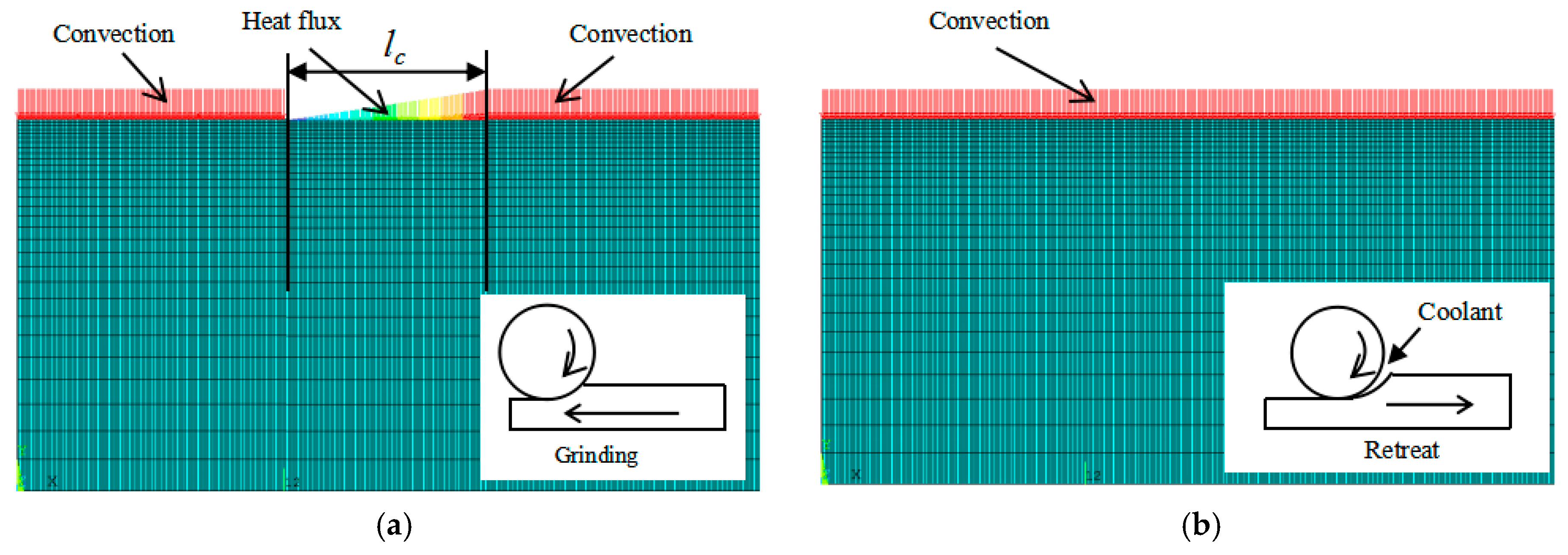
Figure 4.
The signals of grinding force obtained from the measurement system: (a) under the continuous grinding condition; (b) under the intermittent feed grinding condition.
Figure 4.
The signals of grinding force obtained from the measurement system: (a) under the continuous grinding condition; (b) under the intermittent feed grinding condition.

Figure 5.
The signals of grinding temperature obtained from the measurement system.
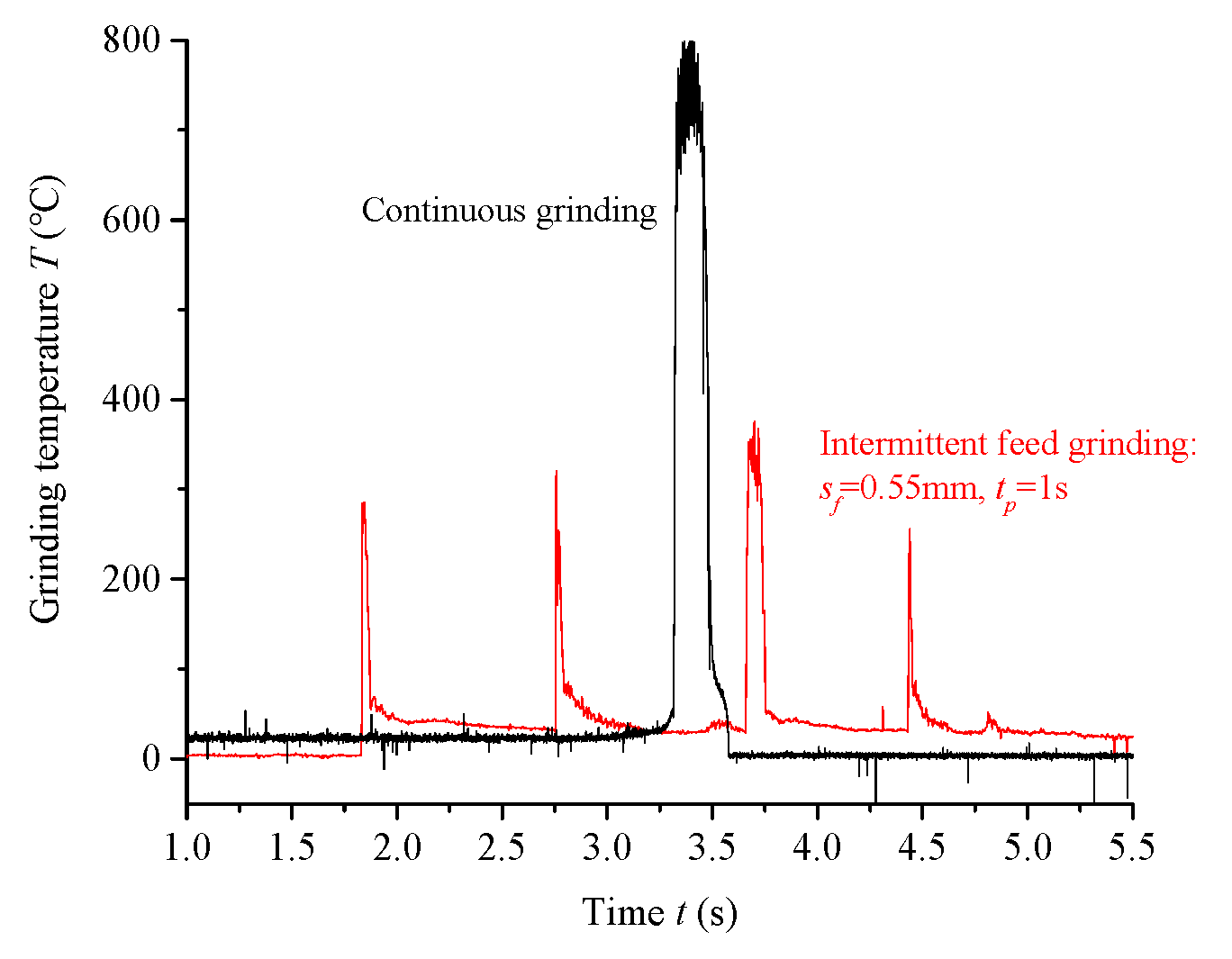
Figure 6.
Variation of grinding force and temperature with wheel speed: (a) grinding force; (b) grinding temperature.
Figure 6.
Variation of grinding force and temperature with wheel speed: (a) grinding force; (b) grinding temperature.

Figure 7.
Variation of grinding force and temperature with grinding depth: (a) grinding force; (b) grinding temperature.
Figure 7.
Variation of grinding force and temperature with grinding depth: (a) grinding force; (b) grinding temperature.

Figure 8.
Variation of grinding force and temperature with single feed distance: (a) grinding force; (b) grinding temperature.
Figure 8.
Variation of grinding force and temperature with single feed distance: (a) grinding force; (b) grinding temperature.

Figure 9.
Variation of grinding temperature distribution with time.

Figure 10.
Time-varying curve of grinding temperature.
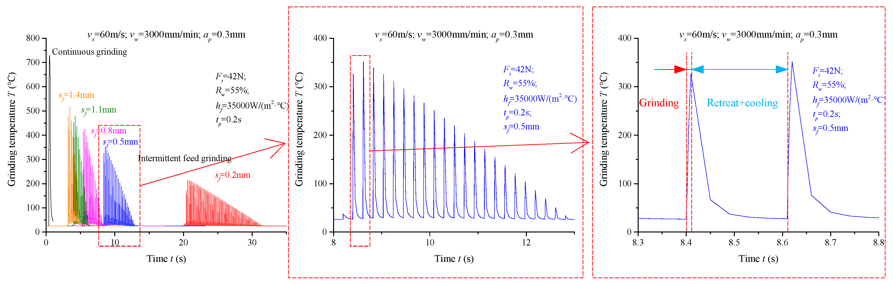
Figure 11.
Variation of Tmax with tp.

Figure 12.
Variation of Tmax with sf.
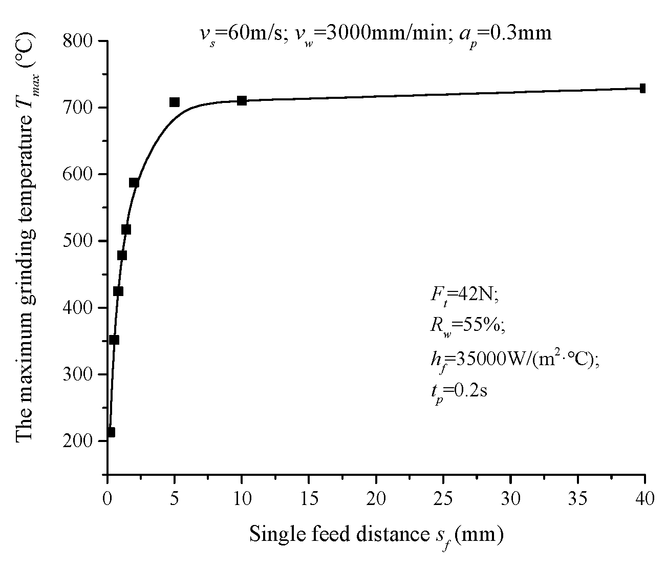
Figure 13.
Comparison between the finite element model (FEM) simulation temperature and the measured temperature.
Figure 13.
Comparison between the finite element model (FEM) simulation temperature and the measured temperature.
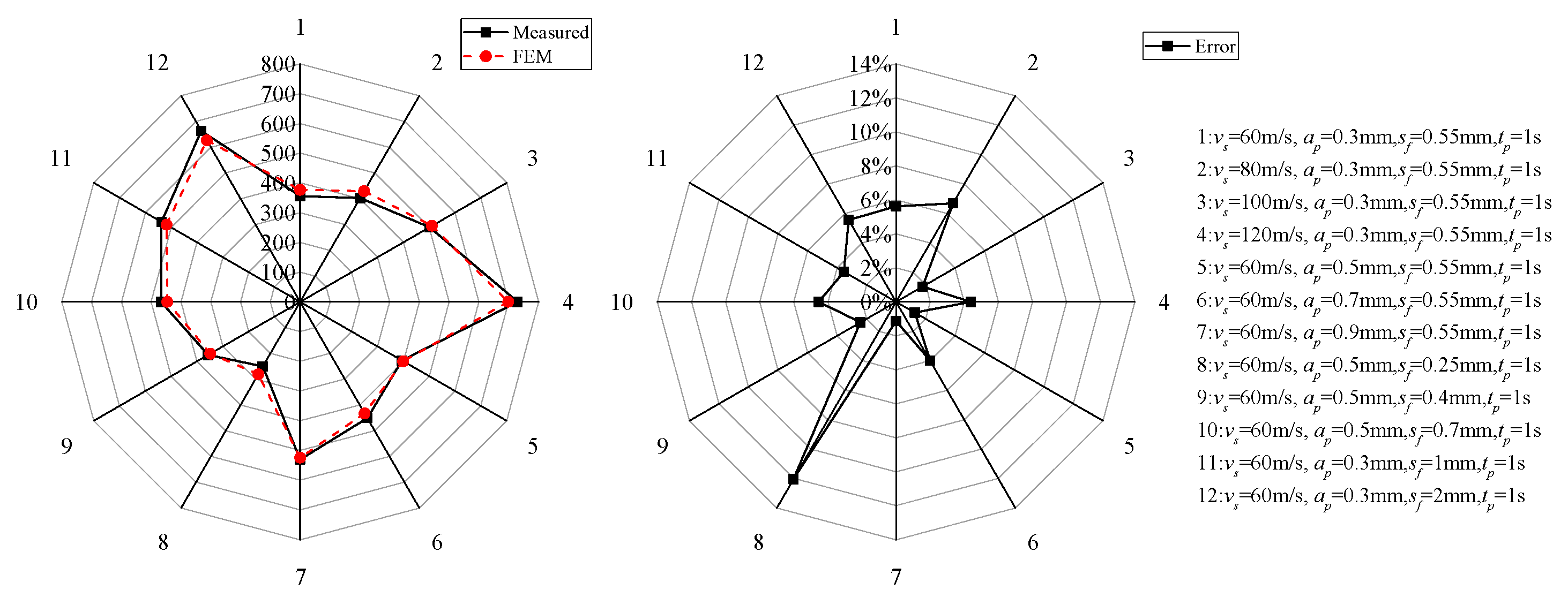
Figure 14.
Von Mises stress contour plot: (a) during conventional grinding; (b) during intermittent feed grinding.
Figure 14.
Von Mises stress contour plot: (a) during conventional grinding; (b) during intermittent feed grinding.

Figure 15.
Surface morphology of grinding wheels: (a) after conventional high-speed grinding; (b) after intermittent feed high-speed grinding.
Figure 15.
Surface morphology of grinding wheels: (a) after conventional high-speed grinding; (b) after intermittent feed high-speed grinding.

Figure 16.
Surface morphology of specimens observed by VHX-1000: (a) after conventional high speed grinding; (b) after intermittent feed high speed grinding.
Figure 16.
Surface morphology of specimens observed by VHX-1000: (a) after conventional high speed grinding; (b) after intermittent feed high speed grinding.

Figure 17.
Surface morphology of specimens observed by SEM: (a) after conventional high-speed grinding; (b) after intermittent feed high-speed grinding.
Figure 17.
Surface morphology of specimens observed by SEM: (a) after conventional high-speed grinding; (b) after intermittent feed high-speed grinding.


Table 1.
The nominal chemical composition of Ti-6Al-4V.
| Chemical Elements | Al | V | Fe | Si | C | N | H | O | Ti |
|---|---|---|---|---|---|---|---|---|---|
| wt % | 6.2 | 4.5 | 0.3 | 0.15 | 0.1 | 0.05 | 0.015 | 0.2 | The rest |
Table 2.
Temperature dependent thermophysical properties of Ti-6Al-4V.
| Temperature °C | Specific Heat Capacity J·Kg−1·°C−1 | Thermal Conductivity W·m−1·°C−1 | Coefficient of Linear Expansion 10−6 m·°C−1 | Young′s Modulus GPa | Yield Strength MPa |
|---|---|---|---|---|---|
| 20 | 611 | 6.8 | 8.4 | 109 | 920 |
| 200 | 653 | 8.7 | 9.2 | 94 | 750 |
| 400 | 691 | 10.3 | 9.5 | 80 | 560 |
| 600 | 713 | 13.7 | 10 | 66 | 340 |
| 700 | 725 | 14.4 | 10.2 | 48 | 280 |
| 800 | 735 | 15.8 | 10.4 | 35 | 130 |
| 1000 | 754 | 18.3 | 10.9 | 22 | 90 |
| 1200 | 771 | 21.7 | 11 | 10 | 66 |
| 1400 | 787 | 24.5 | 11 | 5 | 31 |
Table 3.
Properties of the grinding wheel used in the experiments.
| Property | Abrasive (Cubic Boron Nitride) |
|---|---|
| Density (kg/mm3) | 3480 |
| Specific heat capacity (J/(kg·°C) | 506 |
| Thermal conductivity (W/m·°C) | 700 |
| Thermal diffusivity | 56.8 × 10⁻⁵ |
Table 4.
Dressing conditions.
| Dresser | Diamond Roller |
|---|---|
| Wheel speed vs (m/s) | 30 |
| Dressing speed ratio (vd/vs) | 0.53 |
| Feed speed vw (mm/min) | 300 |
| Single dressing depth ap (μm) | 5, 3, 2 (feed in turn from both sides of the grinding wheel) |
Table 5.
Summary of setup of parameters for the grinding system.
| Wheel Speed vs (m/s) | 60, 80, 100, 120 |
|---|---|
| Worktable feed speed vw (mm/min) | 3000 |
| Grinding depth ap (mm) | 0.3, 0.5 |
| Single feed distance sf (mm) | 0.25, 0.4, 0.55, 0.7, 1, 2 |
| Interval time tp (s) | 1 |
| Coolant | 4% HOCUUT795 coolant, 1 MPa, 25 L/min |
© 2019 by the authors. Licensee MDPI, Basel, Switzerland. This article is an open access article distributed under the terms and conditions of the Creative Commons Attribution (CC BY) license (http://creativecommons.org/licenses/by/4.0/).
Share and Cite
MDPI and ACS Style
Yi, J.; Zhou, W.; Deng, Z. Experimental Study and Numerical Simulation of the Intermittent Feed High-Speed Grinding of TC4 Titanium Alloy. Metals 2019, 9, 802. https://doi.org/10.3390/met9070802
AMA Style
Yi J, Zhou W, Deng Z. Experimental Study and Numerical Simulation of the Intermittent Feed High-Speed Grinding of TC4 Titanium Alloy. Metals. 2019; 9(7):802. https://doi.org/10.3390/met9070802
Chicago/Turabian StyleYi, Jun, Wei Zhou, and Zhaohui Deng. 2019. "Experimental Study and Numerical Simulation of the Intermittent Feed High-Speed Grinding of TC4 Titanium Alloy" Metals 9, no. 7: 802. https://doi.org/10.3390/met9070802
Note that from the first issue of 2016, this journal uses article numbers instead of page numbers. See further details here.