Design for Novel Hot-Work Die Steel by Thermodynamic Calculation and Microstructural Examination
by
 ,
,
Zunjun Zhang
1, 
Jishan Zhang
1,
Zhihao Yao
2,
Guoliang Xie
1,
Yong Lian
3,
Minyu Ma
3,
Chao Zhao
3 and
Jinfeng Huang
1,* 1
State Key Laboratory for Advanced Metals and Materials, University of Science and Technology Beijing, Beijing 100083, China
2
School of Materials Science and Engineering, University of Science and Technology Beijing, Beijing 100083, China
3
Institute for Advanced Materials and Technology, University of Science and Technology Beijing, Beijing 100083, China
*
Author to whom correspondence should be addressed.
Metals 2019, 9(7), 805; https://doi.org/10.3390/met9070805
Submission received: 26 June 2019
/
Revised: 18 July 2019
/
Accepted: 18 July 2019
/
Published: 22 July 2019
Abstract
:In this paper, a new type of hot-work die steel with excellent high-temperature mechanical properties at 700 °C was designed based on the traditional 25Cr3Mo3NiNb steel with the help of Thermo-calc software. The effects of C, Cr, Mo, W and V on the types and mass fractions of carbides were studied. Phase diagram calculation revealed that with the increase of V and W contents and the decrease of Cr content, the precipitation temperature and the mass fraction of M23C6 carbides decreased. Meanwhile, the mass fraction of MC carbides increased as the Mo content decreased. Based on the thermodynamic calculation, new material 25Cr3Mo2NiWVNb steel was designed. Compared to the 25Cr3Mo3NiNb steel, more finely dispersed MC and M2C carbides with high thermal stability, as well as fewer M23C6 carbides with low thermal stability, were precipitated in the new steel. The high-temperature tensile showed that the new steel showed high thermal stability and strength even at 700 °C. The high-temperature strengthening effect might be ascribed to the fine and stable nano-scale MC and M2C carbides which precipitated during tempering.
1. Introduction
Hot working dies have been widely used in the field of machining techniques. With the development of modern industry toward higher efficiency and better precision, the hot work die steel with excellent performance has received extensive attention [1,2,3,4]. In addition to mechanical stress during the die filling process, such as die casting, hot extrusion, hot forging and hot stamping, hot-work die steel also endures rapid heating and cooling impact when interacting with hot metals due to the extremely harsh and complex working environment [5,6]. The high-temperature conditions can influence the material microstructure significantly, which always deteriorates mechanical properties [7,8,9]. The service life of the traditional hot-work dies is limited by insufficient high-temperature performance (especially high-temperature strength), leading to collapse and deformation. In order to prolong the service life of hot-work die steel, it is necessary to enhance high-temperature strength of die steel.
The high-temperature strength of hot work die steel can be enhanced by increasing carbon and alloying element content and micro-alloying, such as V, Nb, Ti and N elements [10,11]. Consequently, various type of carbides will precipitate in the matrix after tempering. The MC, M2C, and M6C carbides have a simple crystal structure with a high melting point and a high hardness [3,12]. These carbides have been reported to be beneficial to improving the hardness and toughness of die steel due to their high hardness and thermal stability. According to [13], a large amount of M2C carbides are precipitated in steel at around 720 °C, which provides a good strengthening effect. However, the M7C3 and M23C6 carbides have poor thermal stability and tend to grow up at high temperature, resulting in the deterioration of mechanical properties [3,12,14,15]. Despite the enhancement of high-temperature strength, its mechanical properties, such as toughness and fatigue performance, decreased significantly, which could be attributed to the coarsening carbides and the high-carbon martensite phase with needle sharp obtained after quenching. Therefore, the traditional methods can hardly achieve the high-temperature strength and the mechanical properties of hot-work die steel simultaneously.
To this end, this work developed new steel based on the “low-carbon low-alloy” design. The effects of alloy elements on the precipitation of carbides were evaluated by phase diagram calculation. Through the reasonable combination of alloying elements, the precipitation of the highly dispersed, nano-scaled, and thermal stable carbides like MC and M2C rather than the M23C6 carbides was promoted after quenching and tempering, so that the lack of high-temperature strength caused by low alloy solution can be overcome.
2. Materials and Methods
2.1. Phase Diagram Calculation and Alloy Design
Table 1 shows the chemical composition of the traditional low-carbon low-alloy hot-work die steel 25Cr3Mo3NiNb. Based on the composition of the alloy, Thermo-calc software (TCFE6, University of Science and Technology Beijing, Beijing, China) was used to optimize alloying elements and high-temperature strength of the alloy. Since the mechanical properties of hot-work die steels are closely related to the carbides in the steel, it is necessary to study the existing carbide-forming elements Cr and Mo in the 25Cr3Mo3NiNb steel. Cr, as a constituent element of Cr23C6, determines the thermal stability [10]. Mo is the main component of M2C carbide, which is important reinforcement for hot-work die steel. Additionally, V is not contained in the alloy, but it has a significant effect on the precipitation of carbides’ type, size and chemical composition. Although W is less able to form carbides, it will provide a good solid solution strengthening effect [4,16,17]. The calculation results in Figure 1 show that there are mainly three kinds of carbides, namely, MC, M6C, and M23C6 carbides in the steel. Some carbides in the steel are not reflected in the calculation, such as the non-equilibrium phases M2C and M7C3. Therefore, by calculating the influence of various alloying elements on the type and quantity of carbide precipitation in 25Cr3Mo3NiNb steel, a reference can be provided for the optimization of alloying elements, thus designing a new alloy with higher high-temperature strength.
2.2. Experimental Materials
The designed 25Cr3Mo2NiWVNb steel and the comparative steel (25Cr3Mo3NiNb) were first melted in a vacuum induction furnace and then casted into 25 kg ingots. The composition design process of the new alloy will be described later. The chemical compositions are shown in Table 2 and Table 3. The ingot was heated to 1130 °C and hot-forged into a rod with a size of φ = 30 mm, and then annealed at 700 °C for 24 h to relief stress. Afterwards, it was cooled to 500 °C with furnace, and cooled to room temperature in the air.
Heat treatment, including annealing, quenching and tempering, is given in Table 4. After heat treatment, the material was processed into a standard high-temperature tensile test sample. The tensile test was performed on a UH-2000 model stretching machine (University of Science and Technology Beijing, Beijing, China) at 700 °C, which is the usual temperature reached by the mold surface. Figure 2 shows the drawing of the specimen used for high-temperature tensile test.
The thin foil for TEM observation were cut into foil 0.3 mm thick from the heat-treated steel, mechanically thinned to about 50 µm, and double-jet electropolished with 5% perchloric acid alcohol solution. The samples were observed by JEOL 2100 TEM (General Research Institute for Nonferrous Metals, Beijing, China).
2.3. The Process of Phase Diagram Calculation and Alloy Design
Table 1 shows the chemical composition of the traditional low-carbon low-alloy hot-work die steel 25Cr3Mo3NiNb. Based on the alloy composition, the effects of alloying elements (V, W, Mo, Cr, C) on the type and mass fraction of the equilibrium precipitated phases were calculated from 0 °C to 1600 °C.
2.3.1. Effects of Elements on M23C6 Carbides
Thermo-calc software was used to carry out thermodynamic calculation of equilibrium precipitation. According to the simulation results (Figure 3), the quantity of M23C6 carbide decreases as the mass fractions of V, W and Mo increase, indicating that V, W, and Mo inhibit the formation of M23C6 carbides. Meanwhile, with the increase of Cr and C mass fractions, the quantity of M23C6 carbides increases, showing that Cr and C elements can promote the formation of M23C6 carbides.
2.3.2. Effects of Elements on M6C Carbides
As shown in Figure 4, the formation of M6C carbides is promoted by V below 500 °C, but suppressed above 500 °C. Overall, Mo and W elements promote the formation of M6C carbides, and Cr element promotes the formation of M6C carbides.
2.3.3. Effects of Elements on MC Carbides
As shown in Figure 5, V has complex effects on the MC carbides in the material. As can be seen from the calculation results, when the V content is about 0.4%, the MC carbide content in the alloy is the highest at about 700 °C. Previous research [16] has shown that the addition of V into the steel can change its carbide type, size and chemical compositions significantly; P. Michaud et al. [17] reported that when the V content increased from 0.47% to 0.84%, the precipitation behavior of carbides changed and the amount of nano-scaled carbides would increase substantially. The above results show that the V content in the steel above 0.4% can significantly affect the carbide precipitation behavior in the alloy, which is consistent with the calculation result. The calculation results are described in Figure 5a. Element W inhibits MC carbides at all temperatures, as shown in Figure 5b–d, show that Mo and Cr elements play important roles in the formation of MC carbides below 1050 °C and below 800 °C, respectively. C element can significantly promote the formation of MC-type carbides. The higher the content of C element, the greater the mass fraction of MC-type carbides in the matrix, and the wider the carbide precipitation temperature range, as shown in Figure 5e.
There are some differences between the simulated carbides and the actual observations results. No M2C or M7C3 carbides can be found in the simulation results. However, M2C carbide has been reported to be an important strengthening phase to provide secondary strengthening effects in Cr-Mo-V hot-work die steel. This is because the calculation is based on the equilibrium conditions, and M2C and M7C3 carbides are non-equilibrium phases for 25Cr3Mo3NiNb steel. If the tempering holding time is extended indefinitely under actual conditions, the experimental results will gradually approach the calculation results.
2.3.4. Comparison of Precipitates between 25Cr3Mo2NiWVNb Steel and 25Cr3Mo3NiNb Steel
According to the above calculation results, appropriate reduction of Mo can inhibit the growth of M2C and M6C carbides. The formation of M23C6 can be inhibited by reducing Cr appropriately. Addition of V and W can inhibit the formation of M23C6, improve the morphology and distribution of MC carbides, and increase the C content slightly, thus increasing the precipitation of carbides and strengthening the strengthening effect of solid solution. The chemical compositions of the new alloy initially were determined by the phase diagram calculations, as shown in Table 5. The compositions for the equilibrium phase diagram calculation (Figure 6) are ω(C) = 0.3%, ω(Cr) = 2.9%, ω(Ni) = 1.4%, ω(Mo) = 1.8%, ω(W) = 0.6%, ω(V) = 0.8%, ω(Nb) = 0.05%. For the sake of convenience, 25Cr3Mo3NiNb steel is called “alloy 1”, and 25Cr3Mo2NiWVNb steel is called “alloy 2”.
It can be seen from the calculation results shown in Figure 7 and Table 6 that the content of MC carbides in alloy 2 at 500–700 °C is significantly higher than that of the comparative material. The M2C carbide appears in the calculation result of alloy 2, but it is not reflected in alloy 1. As long as Mo is added, M2C carbide is one of the main strengthening phases of hot-work die steels [18,19]. This condition may be caused by the less stability and the lower content of the M2C in alloy 1, which can be regarded as a calculation deviation. From the simulation results, it can be found that the M23C6 carbide content in the designed material is slightly higher than that of the comparative material below 360 °C. However, with the increase of temperature, the M23C6 carbide content in the designed material decreases rapidly. This may be related to the decreasing thermal stability of the M23C6 carbide in the developed material with the alloying elements.
2.4. Microstructure
TEM Investigations
Figure 8 and Figure 9 show TEM micrographs of the two types of steel after tempering at 640 °C. Alloy 2 exhibits typical tempered martensite with lath structures and many precipitates, while the lath structures of the comparative material disappear. Figure 10a is a TEM micrograph of a new alloy sample. It shows that a large number of nano-sized short rod-shaped carbides about 5–10 nm long are widely distributed. Similarly, short rod-like carbides are also found in the comparative materials. However, the distribution is less diffuse, and the size is about 80 nm, which is larger than the former.
A considerable number of obvious rod-shaped precipitates are observed in the matrices of the two materials. Alloy 2 contains rod-shaped carbides with different diameters (the length is 5–10 nm and 80–120 nm respectively), while alloy 1 only contains the rod-shaped carbides with a diameter of 10–20 nm and a length of about 80 nm. Previous research [19] has revealed that the rod-shaped carbides in 25Cr3Mo3NiNb are M2C carbides. The corresponding SAED (Selected Area Electron Diffraction) spots of alloy 2 are shown in Figure 8. Figure 11 indicates that the larger size rod-shaped carbide is HCP (Hexagonal Close-packed) cubic structure, and the smaller size rod carbide is FCC (Face-centered Cubic) cubic structure. Figure 8a shows a typical diffraction pattern of M2C carbides while Figure 11 shows that the smaller size rod carbide is MC carbides.
2.5. Mechanical Properties
Table 7 shows the tensile mechanical properties of alloy 1 and alloy 2 after quenching at 1020 °C and tempering at 640 °C. The result displays that alloy 2 has high hardness, room temperature tensile strength and yield strength. The room temperature tensile strength and yield strength of alloy 2 are about 200 MPa higher than those of alloy 1. Table 8 gives the high-temperature strength properties. As the experimental temperature increases to 700 °C, the ultimate tensile strength and the yield strength of the experimental steel are significantly reduced, but alloy 2 is about 100 MPa higher than alloy 1 at 700 °C. The high-temperature elongation of alloy 2 is slightly lower than that of alloy 1.
3. Results and Discussion
During the quenching process, most alloying elements are dissolved back and precipitated on the martensitic matrix in the form of carbides during tempering. The type, size, distribution and stability of carbides precipitated on the tempered martensite matrix determine the mechanical properties of the material. It is well recognized that the M2C carbide formed at high temperature has good tempering softening resistance and secondary hardening [19]. Therefore, after tempering at 640 °C for 2.5 h, alloy 2 still has high hardness and tensile strength. Shi et al. [20] has shown that the stability of M2C carbides determines the stability of martensite laths. For example, the DM steel still has martensite shape after tempering at 700 °C. The fine martensite laths provide stronger resistance to dislocation motion than the recrystallized structure. Alloy 2 contains not only a large number of M2C-type carbides and dispersed nano-sized MC-type carbides, which have outstanding contributions to the thermal stability of lath martensite. Figure 12 shows the microstructure comparison of two materials after stretching at 700 °C. Obviously, alloy 2 still has the apparent martensite lath morphology after stretching at 700 °C, while the martensite lath morphology of alloy 1 almost disappears. When the material is deformed at a high temperature, the lath structure and the dispersed carbides effectively hinder the dislocation motion, thus improving the high-temperature strength substantially. Meanwhile, the increase in deformation resistance leads to a small reduction in elongation.
It has been reported that the addition of V can reduce the diffusion of carbon atoms by forming strong carbides in steel [21]. V is added as a trace element to the alloy, which reduces the diffusion of C, Cr, Mo and Mn atoms [16]. Therefore, fewer C, Cr, Mo, and Mn atoms enter the alloyed carbide, which decreases the size of the carbide. Meanwhile, the reduction in the Mo content further reduces the size of the M2C type carbide. Improving alloying elements not only reduces the size of MC and M2C carbides, but also makes the carbides much finer and more dispersed. It can be seen from Figure 10 and Figure 13 that alloy 2 contains a large number of finely dispersed short rod-shaped carbides (M2C), which effectively block the movement of dislocations, lath boundaries and grain boundaries under high-temperature conditions. As a result, the new alloy has a good thermal stability, and the lath martensite morphology is maintained even after a high-temperature tempering [22,23,24].
4. Conclusions
- (1)
- In order to obtain MC and M2C carbides which are beneficial to thermal stability and high-temperature strength, the contents of V and W were increased while the contents of Mo and Cr were decreased. Meanwhile, Ni was added appropriately to improve the toughness and hardenability of the material.
- (2)
- Based on the thermodynamic calculation, a new material 25Cr3Mo2NiWVNb steel was designed. The new material contains a large amount of nano-sized short rod-shaped MC and M2C carbides (the lengths are 5–10 nm and 80–120 nm respectively). In contrast, the traditional material only contains the rod-shaped carbides with a diameter of 10–20 nm and a length about 80 nm.
- (3)
- The large number of finely dispersed MC carbides and M2C carbides is beneficial for stabilizing martensite lath at high temperatures, which further hinders the dislocation motion at high temperature. The high-temperature strength of the new material is about 30% higher than that of the traditional material.
Author Contributions
Z.Z.: data analysis, writing; J.Z.: study design; Z.Y.: data analysis; G.X.: data analysis; Y.L.: data collection; M.M.: literature search; C.Z.: figures; J.H.: study design.
Funding
This research received no external funding
Conflicts of Interest
The authors declare no conflict of interest.
References
- Gu, J.; Li, J.; Huo, J. Effect of precipitation on hardening and toughening of nitrogen-alloyed H13 steel. Steel Res. Int. 2017, 88, 1700031. [Google Scholar] [CrossRef]
- Katoch, S.; Sehgal, R.; Singh, V. Effect of cryogenic treatment on the tribological behaviour of H11 hot die steel dry sliding against D3 steel. Tribol. Mater. Surf. Interfaces 2016, 10, 185–195. [Google Scholar] [CrossRef]
- Gu, J.; Li, J.; Chen, Y. Microstructure and strengthening-toughening mechanism of nitrogen-alloyed 4Cr5Mo2V hot-working die steel. Metals 2017, 7, 310. [Google Scholar] [CrossRef]
- Li, S.; Wu, X.; Chen, S.; Li, J. Wear resistance of H13 and a new hot-work die steel at high temperature. J. Mater. Eng. Perform. 2016, 25, 2993–3006. [Google Scholar] [CrossRef]
- Barrau, O.; Boher, C.; Gras, R.; Rezai-Aria, F. Analysis of the friction and wear behaviour of hot work tool steel for forging. Wear 2003, 255, 1444–1454. [Google Scholar] [CrossRef] [Green Version]
- Wei, M.X.; Wang, F.; Wang, S.Q.; Cui, X.H. Comparative research on the elevated-temperature wear resistance of a cast hot-working die steel. Mater. Des. 2009, 30, 3608–3614. [Google Scholar] [CrossRef]
- Wang, Q.; Yan, Z.; Liu, X.; Dong, Z.; Fang, H. Understanding of fatigue crack growth behavior in welded joint of a new generation Ni-Cr-Mo-V high strength steel. Eng. Fract. Mech. 2018, 194, 224–239. [Google Scholar] [CrossRef]
- Schaffner, T.; Hartmaier, A.; Kokotin, V.; Pohl, M. Analysis of hydrogen diffusion and trapping in ultra-high strength steel grades. J. Alloys Compd. 2018, 746, 557–566. [Google Scholar] [CrossRef]
- Wang, W.; Wang, K.; Kodur, V.; Wang, B. Mechanical properties of high-strength Q690 steel at elevated temperature. J. Mater. Civ. Eng. 2018, 30, 4018062. [Google Scholar] [CrossRef]
- Dong, J.; Zhou, X.; Liu, Y.; Li, C.; Liu, C.; Guo, Q. Carbide precipitation in Nb-V-Ti microalloyed ultra-high strength steel during tempering. Mater. Sci. Eng. A 2017, 683, 215–226. [Google Scholar] [CrossRef]
- Wang, B.; Li, Z.; Zhan, D.; Jiang, M. Precipitation behavior of VN in high nitrogen and vanadium micro-alloyed low carbon weathering steel. Trans. Indian Inst. Met. 2018, 71, 1607–1613. [Google Scholar] [CrossRef]
- Delagnes, D.; Lamesle, P.; Mathon, M.H.; Mebarki, N.; Levaillant, C. Influence of silicon content on the precipitation of secondary carbides and fatigue properties of a 5% Cr tempered martensitic steel. Mater. Sci. Eng. A 2005, 394, 435–444. [Google Scholar] [CrossRef]
- Ishii, R.; Tsuda, Y.; Yamada, M.; Kimura, K. Fine precipitates in high chromium heat resisting steels. Tetsu-to-Hagané 2009, 88, 36–43. [Google Scholar] [CrossRef]
- Mebarki, N.; Delagnes, D.; Lamesle, P.; Delmas, F.; Levaillant, C. Relationship between microstructure and mechanical properties of a 5% Cr tempered martensitic tool steel. Mater. Sci. Eng. A 2004, 387, 171–175. [Google Scholar] [CrossRef]
- Wu, D.; Wang, F.; Cheng, J.; Li, C. Effects of Nb and tempering time on carbide precipitation behavior and mechanical properties of Cr–Mo–V steel for brake discs. Steel Res. Int. 2018, 89, 1700491. [Google Scholar] [CrossRef]
- Wen, T.; Hu, X.; Song, Y.; Yan, D.; Rong, L. Carbides and mechanical properties in a Fe–Cr–Ni–Mo high-strength steel with different V contents. Mater. Sci. Eng. A 2013, 588, 201–207. [Google Scholar] [CrossRef]
- Michaud, P.; Delagnes, D.; Lamesle, P.; Mathon, M.H.; Levaillant, C. The effect of the addition of alloying elements on carbide precipitation and mechanical properties in 5% chromium martensitic steels. Acta Mater. 2007, 55, 4877–4889. [Google Scholar] [CrossRef] [Green Version]
- Zhou, Q.; Wu, X.; Shi, N.; Li, J.; Min, N. Microstructure evolution and kinetic analysis of DM hot-work die steels during tempering. Mater. Sci. Eng. A 2011, 528, 5696–5700. [Google Scholar] [CrossRef]
- Wang, M.; Dong, H.; Wang, Q. Elevated-temperature properties of one long-life high-strength gun steel. Rare Met. 2004, 11, 67. [Google Scholar]
- Shi, Y.J.; Wu, X.C.; Li, J.W.; Min, N. Tempering stability of Fe-Cr-Mo-W-V hot forging die steels. Int. J. Min. Met. Mater. 2017, 24, 1145–1157. [Google Scholar] [CrossRef]
- Kelly, A.; Nicholson, R.B. Strengthening Methods in Crystals; Halstead Press Division, John Wiley & Sons: New York, NY, USA, 1971. [Google Scholar]
- Palmiere, E.J.; Garcia, C.I.; Deardo, A.J. The influence of niobium supersaturation in austenite on the static recrystallization behavior of low carbon microalloyed steels. Metall. Mater. Trans. A 1996, 27, 951–960. [Google Scholar] [CrossRef]
- Dutta, I.; Bourell, D.L. Influence of dislocation density and distribution on the aging behavior of 6061 Al SiCw composites. Acta Metall. Mater. 1990, 38, 2041–2049. [Google Scholar] [CrossRef]
- Rahmanifard, R.; Farhangi, H.; Novinrooz, A.J. Development of mechanical performance of 12YWT steel nanocomposite by addition of zirconium and tantalum. J. Alloys Compd. 2016, 657, 646–654. [Google Scholar] [CrossRef]
Figure 1.
Thermodynamic calculation results for 25Cr3Mo3NiNb.
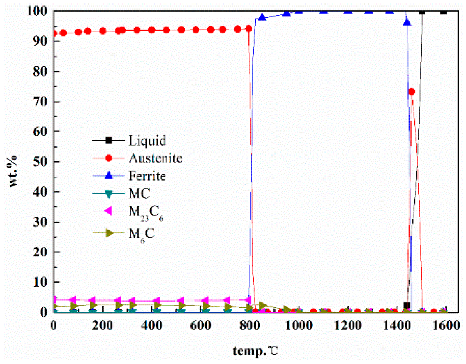
Figure 2.
The drawing of high-temperature tensile specimen. (mm)

Figure 3.
Effects of alloying elements on M23C6 carbides. (a) Effect of V on M23C6; (b) effect of W on M23C6; (c) effect of Mo on M23C6; (d) effect of Cr on M23C6; (e) effect of C on M23C6.
Figure 3.
Effects of alloying elements on M23C6 carbides. (a) Effect of V on M23C6; (b) effect of W on M23C6; (c) effect of Mo on M23C6; (d) effect of Cr on M23C6; (e) effect of C on M23C6.

Figure 4.
Effects of alloying elements on M6C carbides. (a) Effect of V on M6C; (b) effect of W on M6C; (c) effect of Mo on M6C; (d) effect of Cr on M6C; (e) effect of C on M6C.
Figure 4.
Effects of alloying elements on M6C carbides. (a) Effect of V on M6C; (b) effect of W on M6C; (c) effect of Mo on M6C; (d) effect of Cr on M6C; (e) effect of C on M6C.
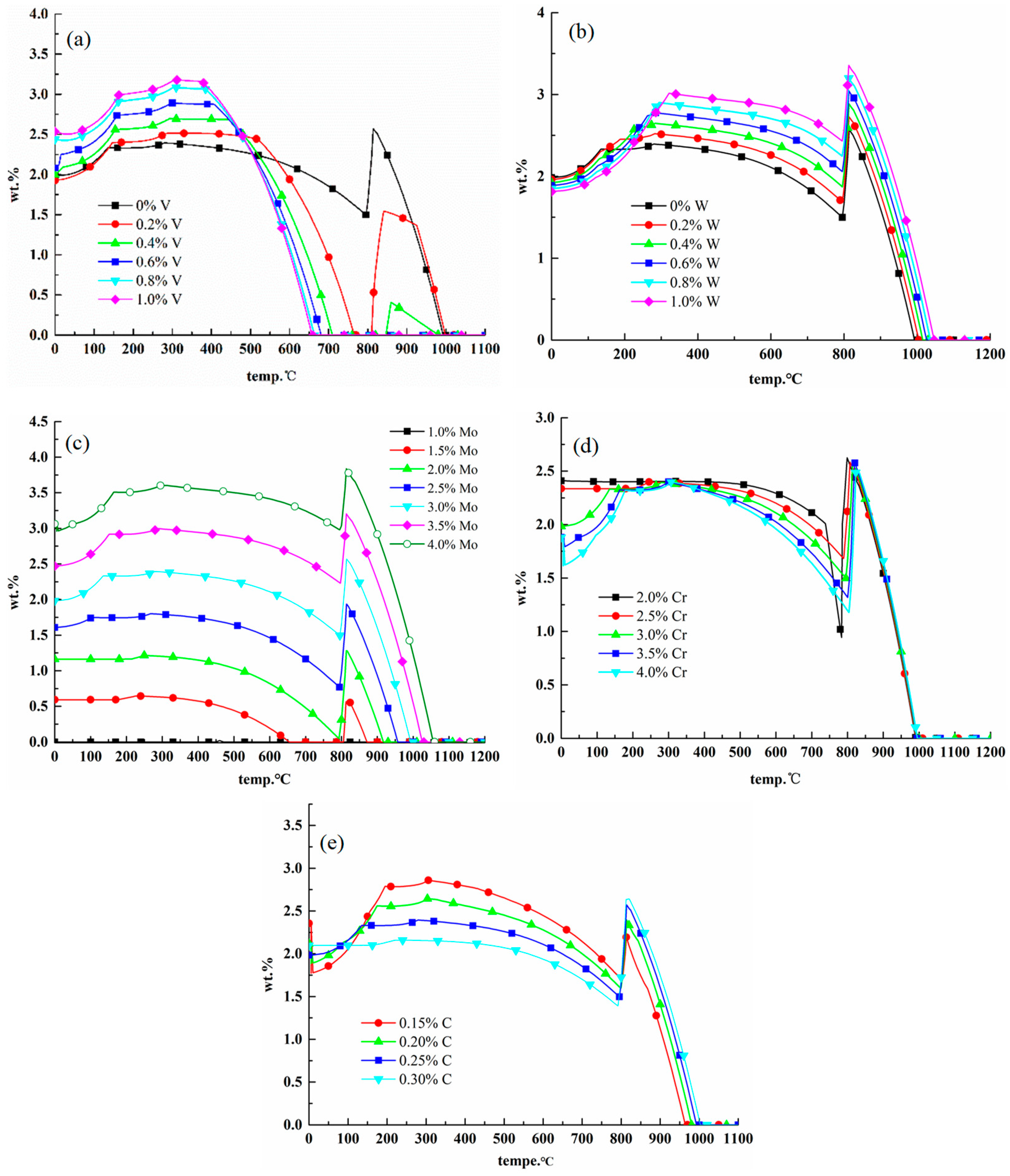
Figure 5.
Effects of alloying elements on MC carbides. (a) Effect of V on MC; (b) effect of W on MC; (c) effect of Mo on MC; (d) effect of Cr on MC; (e) effect of C on MC.
Figure 5.
Effects of alloying elements on MC carbides. (a) Effect of V on MC; (b) effect of W on MC; (c) effect of Mo on MC; (d) effect of Cr on MC; (e) effect of C on MC.

Figure 6.
Alloy 2 equilibrium phase diagram.

Figure 7.
Comparison of carbides—both materials.

Figure 8.
TEM images showing different kinds of precipitates of 25Cr3Mo2NiWVNb steel after tempering at 640 °C. (a) M2C; (b) M6C; (c) MC; (d) the corresponding diffraction pattern of MC.
Figure 8.
TEM images showing different kinds of precipitates of 25Cr3Mo2NiWVNb steel after tempering at 640 °C. (a) M2C; (b) M6C; (c) MC; (d) the corresponding diffraction pattern of MC.

Figure 9.
TEM micrographs of two kinds of precipitates in 25Cr3Mo3NiNb steel after tempering at 640 °C.
Figure 9.
TEM micrographs of two kinds of precipitates in 25Cr3Mo3NiNb steel after tempering at 640 °C.

Figure 10.
TEM micrographs of two kinds of nano-sized short rod-shaped precipitates in different steels. (a) 25Cr3Mo2NiWVNb steel; (b) 25Cr3Mo3NiNb.
Figure 10.
TEM micrographs of two kinds of nano-sized short rod-shaped precipitates in different steels. (a) 25Cr3Mo2NiWVNb steel; (b) 25Cr3Mo3NiNb.

Figure 11.
The corresponding SAED pattern of nano-sized short rod-shaped precipitates in 25Cr3Mo2NiWVNb steels.
Figure 11.
The corresponding SAED pattern of nano-sized short rod-shaped precipitates in 25Cr3Mo2NiWVNb steels.

Figure 12.
Microstructure comparison of two materials after stretching at 700 °C. (a) Alloy 1; (b) alloy 2.
Figure 12.
Microstructure comparison of two materials after stretching at 700 °C. (a) Alloy 1; (b) alloy 2.

Figure 13.
MC carbides, M2C carbides and dislocation groups in alloy 2.


Table 1.
Chemical composition of 25Cr3Mo3NiNb for phase diagram calculation.
| Elements | C | Ni | Cr | Mo | Nb |
|---|---|---|---|---|---|
| wt% | 0.25 | 0.65 | 3 | 3 | 0.1 |
Table 2.
25Cr3Mo2NiWVNb steel composition (mass fraction, %).
| Elements | C | Ni | Cr | Mo | V | W | Nb | Fe |
|---|---|---|---|---|---|---|---|---|
| Chemical compositions | 0.29 | 1.45 | 2.50 | 2.18 | 0.46 | 0.58 | 0.05 | Bal. |
Table 3.
25Cr3Mo3NiNb steel composition (mass fraction, %).
| Elements | C | Ni | Cr | Mo | Nb | Fe |
|---|---|---|---|---|---|---|
| Chemical compositions | 0.28 | 0.65 | 3.00 | 2.9 | 0.08 | Bal. |
Table 4.
Heat treatment process of test steels.
| Heat Treatment Process | Heat Treatment Process System |
|---|---|
| Annealing process | Annealed at 870 °C for 2 h, cooled to 500 °C at a cooling rate of 30 °C/h, and then cooled down to room temperature in the air |
| Quenching process | Austenitization temperature at 1020 °C holding for 1 h, followed by an immediate water-quench to room temperature |
| Tempering process | Tempered at 640 °C for 2.5 h after quenching, cooled down to room temperature in the air |
Table 5.
Preliminarily formulated alloy 25Cr3Mo2NiWVNb composition range.
| Elements | C | Si | Mn | Ni | Cr | V | Mo | W | Nb |
|---|---|---|---|---|---|---|---|---|---|
| wt% | 0.27–0.32 | ≤0.10 | ≤0.10 | 1.3–1.5 | 2.0–3.0 | 0.3–1.0 | 1.5–2.5 | 0.40–0.70 | 0.03–0.1 |
Table 6.
Comparing the information calculated from the balance phase of alloy 1 and alloy 2.
| Balanced Phase | 25Cr3Mo3NiNb (Alloy 1) | 25Cr3Mo2NiWVNb (Alloy 2) | ||||
|---|---|---|---|---|---|---|
| Content at 500 °C | Content at 600 °C | Content at 700 °C | Content at 500 °C | Content at 600 °C | Content at 700 °C | |
| MC | 0.0987% | 0.109% | 0.117% | 0.787% | 0.81% | 0.557% |
| M6C | 2.26% | 2.11% | 1.85% | 1.4% | 1.05% | 0% |
| M23C6 | 3.84% | 3.91% | 4.05% | 3.92% | 3.73% | 3.32% |
| M2C | 0 | 0 | 0 | 0 | 0.239% | 1.283% |
Table 7.
Mechanical properties of alloy 1 and alloy 2 after heat-treatment processes.
| Steel | Ultimate Tensile Strength/MPa | Yield Strength/MPa | Elongation/% | Hardness/HRC |
|---|---|---|---|---|
| Alloy 1 | 1180 | 920 | 18.5 | 35.5 |
| Alloy 2 | 1374 | 1178 | 17 | 43 |
Table 8.
High-temperature tensile test properties of two alloys.
| Materials | Test Temperature/°C | Ultimate Tensile Strength/MPa | Yield Strength/MPa | Elongation/% |
|---|---|---|---|---|
| Alloy 1 | 700 | 380 | 277 | 24.0 |
| Alloy 2 | 700 | 495 | 385 | 21.0 |
© 2019 by the authors. Licensee MDPI, Basel, Switzerland. This article is an open access article distributed under the terms and conditions of the Creative Commons Attribution (CC BY) license (http://creativecommons.org/licenses/by/4.0/).
Share and Cite
MDPI and ACS Style
Zhang, Z.; Zhang, J.; Yao, Z.; Xie, G.; Lian, Y.; Ma, M.; Zhao, C.; Huang, J. Design for Novel Hot-Work Die Steel by Thermodynamic Calculation and Microstructural Examination. Metals 2019, 9, 805. https://doi.org/10.3390/met9070805
AMA Style
Zhang Z, Zhang J, Yao Z, Xie G, Lian Y, Ma M, Zhao C, Huang J. Design for Novel Hot-Work Die Steel by Thermodynamic Calculation and Microstructural Examination. Metals. 2019; 9(7):805. https://doi.org/10.3390/met9070805
Chicago/Turabian StyleZhang, Zunjun, Jishan Zhang, Zhihao Yao, Guoliang Xie, Yong Lian, Minyu Ma, Chao Zhao, and Jinfeng Huang. 2019. "Design for Novel Hot-Work Die Steel by Thermodynamic Calculation and Microstructural Examination" Metals 9, no. 7: 805. https://doi.org/10.3390/met9070805
Note that from the first issue of 2016, this journal uses article numbers instead of page numbers. See further details here.