Numerical Study on the Formability of Metallic Bipolar Plates for Proton Exchange Membrane (PEM) Fuel Cells


1
CEMMPRE, Department of Mechanical Engineering, University of Coimbra, Rua Luís Reis Santos, Pinhal de Marrocos, 3030-788 Coimbra, Portugal
2
CMEMS, Microelectromechanical Systems Research Unit, University of Minho, Campus de Azurém, 4800-058 Guimarães, Portugal
*
Author to whom correspondence should be addressed.
Metals 2019, 9(7), 810; https://doi.org/10.3390/met9070810
Submission received: 10 July 2019
/
Revised: 19 July 2019
/
Accepted: 21 July 2019
/
Published: 23 July 2019
(This article belongs to the Special Issue Modelling and Simulation of Sheet Metal Forming Processes)
Abstract
:Thin stamped bipolar plates (BPPs) are viewed as promising alternatives to traditional graphite BPPs in proton exchange membrane fuel cells. Metallic BPPs provide good thermal/electrical conductivity and exhibit high mechanical strength, to support the loads within the stack. However, BPPs manufactured by stamping processes are prone to defects. In this study, the effect of the tool’s geometry on the thin sheet formability is investigated through finite element simulation. Despite the broad variety of flow field designs, most of BPPs comprise two representative zones. Hence, in order to reduce the computational cost, the finite element analysis is restricted to these two zones, where the deformation induced by the stamping tools is investigated. The channel/rib width, the punch/die fillet radii, and the channel depth are the parameters studied. The analysis is conducted for a stainless steel SS304 with a thickness of 0.15 mm. The results show that the maximum value of thinning occurs always in the U-bend channel section, specifically in the fillet radius of the die closest to the axis of revolution.
1. Introduction
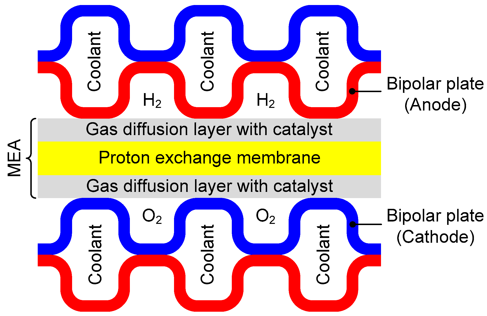
In the last years, fuel cell technology has received increasing attention due to the growing concerns about the depletion of fossil fuels and climate changes [1]. The proton exchange membrane (PEM) fuel cells emerged as one promising candidate to replace internal combustion engines in the automotive industry, producing electricity from the electrochemical reaction between hydrogen and oxygen [2]. They are characterised by: (i) low operation temperatures (<100 °C); (ii) quick start-up; (iii) high power density; (iv) high efficiency; and (v) low greenhouse gas emissions [3]. The main drawbacks of the fuel cells are the high manufacturing cost and the low durability, which prevent their widespread commercialization [4]. For transportation applications, the 2015 US Department of Energy (DOE) targets for the fuel cell cost and lifetime are $30/kW and 5000 h, respectively, which are in line with the automotive internal combustion engine systems [5]. The key components of a PEM fuel cell are the bipolar plates (BPPs) and the membrane electrode assembly (MEA). The last comprises the PEM, the gas diffusion layer (GDL), and a catalyst layer, as presented schematically in Figure 1.
The BPPs are key elements of a PEM fuel cell, comprising about 60–80% of the stack weight and up to 30–50% of the stack manufacturing cost [6]. They are multifunctional components responsible for: (i) supplying a uniform distribution of the reactant gases (H2 and O2) over the electrodes via flow channels; (ii) removing the heat and reaction products (water) from the cell assembly; (iii) connecting electrically the cathode of one cell to the anode of the adjacent cell (that is why they are called BPPs); and (iv) providing structural support for the thin and mechanically weak MEA. Therefore, an ideal material for BPPs should comprise the following properties: high electrical conductivity, low gas permeability, high corrosion resistance in acidic environments, high mechanical strength, and low cost [7]. The earlier BPPs were fabricated from high-density graphite, which is chemically stable (excellent corrosion resistance) and possesses high thermal/electrical conductivity [8]. Nevertheless, the graphite plates are brittle, exhibit low mechanical strength, and present high manufacturing cost, resulting from the need to mill the flow field channels [3]. Accordingly, several studies have been performed in order to develop more suitable and cost-effective materials for the fabrication of BPPs, such as metals and composites [9]. Further, the adoption of metallic materials allows for the application of other manufacturing techniques, including stamping [10], hydroforming [11], rubber pad forming [12], micro-electrical discharge machining (μEDM) [13], electrochemical micro-machining [14], and vacuum die casting [15].
Among the metals candidates for BPPs, stainless steels, Ni-based alloys, Ti-based alloys, and Al-based alloys have been considered for PEM fuel cells [6]. The stainless steel is presently a consensual material for BPPs, due to its relatively high strength, high chemical stability, high electrical conductivity, low gas permeability, and much lower manufacturing cost in comparison with graphite [7]. The main drawbacks of metals are the high density and the weak corrosion resistance [16]. Regarding the high density, it can be alleviated by using ultra-thin sheets (51 μm of thickness) [17], which requires the adopting of different forming methods to produce the BPPs [18]. The corrosion of the BPPs leads to a release of metal ions, which contaminate the PEM [19,20]. In addition, a passive film of oxides is generated on the BPP surface during the fuel cell operation, which increases the interfacial contact resistance between the BPPs and the GDL [21]. Both previously mentioned conditions significantly reduce the stack performance and lifetime [22]. Thus, several studies have been carried out in the last years to improve the corrosion resistance (eliminate the passive film) using coatings [23]. Some corrosion-resistant-treated metal BPPs show a 12% saving in hydrogen consumption and higher efficiency in relation to graphite [24].
The metallic BPPs manufactured by forming processes received raised interest in the last years, namely the stainless steels, since they are promising candidates to replace the graphite at low cost for massive production of fuel cells [7]. However, different forming defects can occur in the forming of ultra-thin BPPs, such as springback, wrinkles, thinning, and fracture [10]. Accordingly, several strategies have been proposed to improve the formability and reduce the forming defects. In order to obtain deeper channels on the BPPs, dynamic loads (sine and square waves) are applied in the stamping process of the 0.1 mm-thick austenitic stainless steel SS304 [25]. The forming depth of the BPP increases up to 10%, in comparison with the static load, when the number of cycles is over five. On the other hand, Park et al. [26] explored the use of solution heat treatment to improve the formability of two stainless steels (SS304 and SS316). Since the ductility increases after applying the heat treatment, the channel depth achieved in the stamping process doubles for the heat-treated sheet. Recently, Bong et al. [27] proposed the adoption of a multi-stage forming approach to improve the formability of ultra-thin ferritic stainless steel.
Since the flow field configuration of BPPs is usually defined by a channel pattern (see Section 2), most of the numerical studies of the stamping process reported in the literature consider plane strain conditions and they are restricted to the analysis of a single channel. Nevertheless, the accurate modelling of the forming conditions requires the study of different regions, which comprise distinct strain paths. Therefore, the purpose of this study is to assess the formability of BPPs manufactured by stamping, considering two representative zones of the BPPs (straight and the U-bend channel sections), which are analysed in detail using finite element simulation. The developed numerical model aims to provide a reference for optimizing stamping process of BPPs. Section 2 contains a brief presentation of the flow field configurations currently used in PEM fuel cells, in order to highlight their common geometrical features. The proposed finite element model adopted in the analysis of the stamping process is presented in Section 3, namely the model adopted to describe the mechanical behaviour of the stainless steel and the process conditions. Section 4 comprises the results for the straight channel section, where the effect of the cross-section geometry on the deformation is analysed considering plane strain conditions. The results regarding the U-bend channel section are presented in Section 5, highlighting the influence of tools geometry on the formability of stamped BPPs, as well as the importance of the adopted boundary conditions. The main conclusions of this study are discussed in Section 6.
2. Flow Field Configurations
The main functions of the flow field in a BPP is to distribute evenly the reactant gases (H2 and O2) over the respective GDL and remove the water produced during the reaction. Since the performance of the PEM fuel cell is strongly affected by the flow field design, several numerical models have been developed to analyse the coupled transport process and electrochemical reaction in PEM fuel cells [28]. Typically, the flow field configurations can be divided into five types: parallel, interdigitated, pin-type, spiral, and serpentine, which are schematically illustrated in Figure 2. The serpentine flow field, either containing single (Figure 2e) or multiple channels (Figure 2f), is the most commonly used design in commercial fuel cells [29]. The effect of the gas flow fields design on the fuel cell performance was investigated experimentally by Dhahad et al. [30]. On the other hand, the modelling of an optimum flow field design was presented by Kahraman and Orhan [31], including a parametric study with respect to different design and performance parameters in a flow field plate. In addition to the conventional flow field patterns, some nature-inspired flow field designs have been studied recently [32]. The results show that the bio-inspired interdigitated designs improve the fuel cell performance by about 20–25%, in comparison with the conventional designs [33]. However, the manufacturing complexity leads to significant costs because typically these BPPs are made from graphite composite and produced by a selective laser sintering process.
In addition to the gas flow field configuration, several studies have been carried out to optimise the channel geometries (dimensions and shape) in order to achieve better fuel cell’s performance [34]. Since originally the channels of the BPPs were milled on graphite plates, most of the studies are focused on the rectangular channel geometry [35]. The influence of the channel cross-section aspect ratio (height/width) on the performance of a PEM fuel cell was numerically investigated by Manso et al. [36]. They concluded that fuel cell models with high channel cross-section aspect ratios present better performance, due to the increasing mass transport. On the other hand, the effect of the channel/rib width ratio on PEM fuel cell performance was assessed by Shimpalee and Van Zee [34], using computational fluid dynamics simulation. The results show that for automotive applications the performance is higher for a wider channel with narrower rib spacing, indicating that the heat removal from the MEA is less important than the water management.
The adoption of graphite BPPs or thick metallic BPPs fabricated by milling allows obtaining independent flow field configurations on each side of the plate. Nevertheless, for thin metallic BPPs manufactured by a stamping process, the flow field configuration of one side of the plate is always determined by the configuration of the opposite side, because both sides are formed simultaneously. Indeed, it is difficult to obtain two continuous channels on both sides of a single BPP to provide reactant and cooling flow field, respectively [37]. Thus, typically the reactant flow channel is continuous, with exception to the interdigitated channel (Figure 2b). Moreover, the cross-section of the flow channels in BPPs manufactured by a stamping process is shaped like a trapezoidal with fillets. Hence, Xu et al. [38] recently established a model to calculate the influence of the tapered channel geometry on the pipe resistance and flow distribution.
3. Finite Element Model
In order to analyse the stamping process used to manufacture metallic BPPs, the influence of the tools geometry on the formability was assessed using finite element simulation. The numerical simulations of the stamping process were carried out with the in-house static implicit finite element code DD3IMP [39], specifically developed to simulate sheet metal forming processes [40,41]. Its main characteristic is the use of a fully implicit algorithm of Newton–Raphson type to solve, within a single iterative loop, the non-linearities related with the frictional contact problem and the elastoplastic behaviour of the deformable body. All simulations were performed on a computer machine equipped with an Intel® Core™ i7-4770K Quad-Core processor (3.5 GHz frequency) and the Windows® 10 (64-bit platform) operating system.
3.1. Material Properties
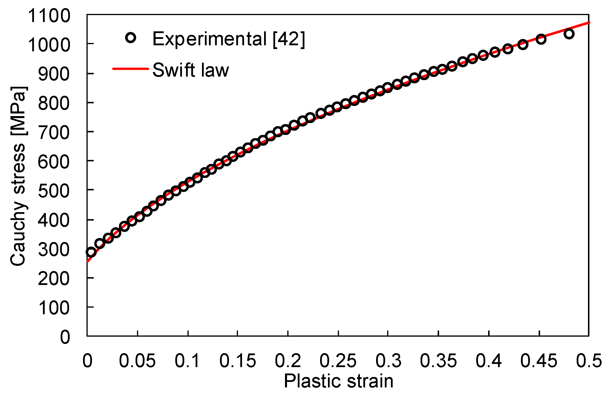
The metal sheet considered in this study is of austenitic stainless steel SS304 with a thickness of 0.15 mm, which is commonly used in the sheet metal forming of BPPs [25]. The mechanical behaviour of this ultra-thin sheet of stainless steel was experimentally evaluated by Pham et al. [42]. The stress–strain curve recorded in the experimental uniaxial tensile test (initial strain rate of 10−3 s−1) is used in the present study to define the material parameters in the numerical model. Hence, the elastic behaviour of the stainless steel is considered isotropic and constant, which is described by the Hooke’s law with an Young’s modulus of 206.2 GPa and a Poisson ratio of 0.30 [42]. Regarding the plastic response, the work hardening behaviour is described by the phenomenological Swift hardening law, where the flow stress, , is given by:
where denotes the equivalent plastic strain, while , , and n are the material parameters.
The parameters of the Swift hardening law were identified using the stress–strain curve of the experimental tensile test, presented in Figure 3. The identification procedure is based on the minimization of a cost function, which evaluates the difference between numerical and experimental stress values, using least squares estimation. The obtained material parameters for the isotropic hardening law are listed in Table 1, which are identical to the ones adopted in the numerical model used by Hu et al. [10]. The comparison between the experimental and numerical stress–strain curves is presented in Figure 3, highlighting the accurate description of the work hardening behaviour by the Swift law.
The plastic anisotropy coefficients of the stainless steel SS304 were experimentally calculated by Pham et al. [43] in the rolling and transverse directions. They obtained similar values for both directions, close to 0.9, which are in agreement with the values presented by Raj [44] for the SS304 with a thickness of 0.5 mm. However, in the present study, the behaviour of the metal sheet is assumed isotropic and modelled by the von Mises yield function, in order to avoid the influence of the orientation of the sheet. In fact, the experimental study conducted by Park et al. [26] shows that the influence of the sheet orientation (channel parallel or perpendicular to the rolling direction of the sheet) on the maximum channel depth is insignificant.
3.2. Stamping Process
The high productivity and the low cost of mass production are the main advantages of the stamping process for BPPs manufacturing. The desired geometry of the ultra-thin BPP (flow field and channel geometry) is obtained by plastic deformation induced by the forming tools operation (displacement control). Typically, the forming tools are assumed rigid in the numerical simulation, while the deformation of the metallic sheet is described by an elastoplastic material model (strain rate-insensitive), as described in the previous section. Hence, in the present study, the tools surface is discretized with Nagata patches [45,46]. The blank sheet is discretized with linear hexahedral finite elements using a selective reduced integration technique [47] to avoid volumetric locking. In order to accurately capture the through-thickness gradients (stress and strain), all simulations use six finite elements in the thickness direction. Despite the large computation time associated with the solid finite elements, they are required for accurate predictions when the ratio between the tool fillet radius and the sheet thickness is lower than five [48]. The friction between the blank and the forming tools is modelled through the classical Coulomb’s law. The value of the constant friction coefficient adopted in the finite element model is selected as μ = 0.1, which is within the range of values commonly used in the numerical simulation of BPPs stamping [10,27].
Due to the large geometric complexity of the ultra-thin BPPs (see the example shown in Figure 4 [49]), the finite element simulation of the stamping process is commonly carried out under plane strain conditions, i.e., simplified two-dimensional (2D) finite element models are used to study locally a few numbers of channels [50]. In fact, the number of finite elements required to describe accurately the entire BPP is very high, since the minimum fillet radius of the channel is considerably smaller in comparison with the BPP size. Therefore, in the present work, specific areas of the BPP are studied by finite element simulation, namely the straight and the U-bend channel sections indicated in Figure 4. Despite the variety of flow field configurations (see Figure 2), these two channel sections are usually present in the BPPs, allowing evaluating different deformation mechanisms existent in the BPPs stamping process.
4. Straight Channel Section
Since the main region of a flow channel is straight (see Figure 4), the effect of the cross-section geometry on the deformation is numerically analysed using plane strain conditions. The geometry of the trapezoidal channel obtained by sheet metal forming (see Figure 5a) is usually defined by five key parameters: (i) channel depth (h); (ii) channel width (w1); (iii) rib width (s); (iv) draft angle (θ); and (v) fillet radii (r and R). These dimensions are dictated mainly by the geometry of the forming tools (punch and die) and the stamping process conditions. Hence, the influence of the tool dimensions (see Figure 5a) on the formability of stamped BPPs was assessed in the present study through the thinning and the equivalent plastic strain predicted by numerical simulation. The fillets in the trapezoidal shape of the channel cross-section are defined by the fillet radius of the punch and die (see Figure 5b). For a predefined channel height, the angle between the walls of the channel (draft angle θ) is directly related to the ratio between the channel width w1 and the dimension w2, as shown in Figure 5. Since the die position is fixed in the numerical model, the channel depth is simply dictated by the prescribed vertical displacement of the punch.
Regarding the stainless steel BPPs manufactured by a stamping process, the review carried out by Peng et al. [7] summarizes the range of values currently used for each key parameter that defines the flow channel (cross-section). The initial thickness of the stainless steel sheets used in the forming process of BPPs ranges between 0.051 mm [18] and 0.15 mm [10]. Based on the previous studies, the values of channel width range from 0.75 mm [18] to 1.5 mm [10]. On the other hand, since the channel cross-section aspect ratio is usually lower than 0.5, the channel depth ranges between 0.20 mm [18] and 0.60 mm [51]. In fact, the channel depth reached by forming (before fracture) is always inferior to 5 times the initial thickness. In order to simplify the sensitivity analysis performed in this study, some simplifications are introduced in the geometry of the forming tool. Hence, the rib width is selected to be equal to the channel width (w1 = s) and the fillet radius of the punch and die are assumed identical in the 2D plane strain finite element model, i.e., r = R.
4.1. Multiple Channels
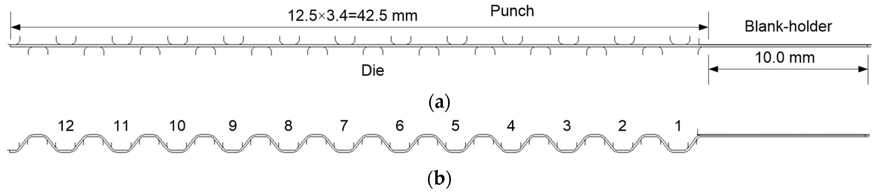
Although the numerical simulation of the forming process is usually restricted to a single channel [50], BPPs are composed by a set of parallel channels (see Figure 4). The proximity of the channel to the blank edges can change the local process conditions in terms of restraining force. The border effect on the channel geometry was experimentally studied by Mahabunphachai et al. [18] for stamped BPPs. They show that for a BPP with 26 parallel channels, the height of each one varies according to its position, presenting variations of about 25% (higher values of channel height closer to the blank edges). Therefore, in order to quantify the influence of the adopted boundary conditions on the numerical results, a stamped BPP composed by 25 parallel channels is analysed under plane strain conditions. Due to symmetry conditions, only half BPP width is simulated (see Figure 6), which is discretized with 3000 × 6 = 18,000 finite elements. In order to account for the border effect, the rib width is extended (10 mm) and a blank-holder is added to allow clamping the blank during the forming, as shown in Figure 6a. The dimensions of the forming tools (punch and die) are presented in Table 2.
The predicted final geometry of the BPP is presented in Figure 6b assuming a channel depth of h = 1.0 mm (punch displacement), highlighting the trapezoidal shape of the channel cross-section in stamped BPPs. In order to cover a wide range of experimental clamping conditions, applied during the stamping process, three distinct boundary conditions are adopted in the numerical model. They are defined by: (i) an unconstrained free edge of the flange with the blank-holder placed over the flange with a fixed gap (initial thickness of the blank); (ii) an unconstrained free edge of the flange and application of a constant force on the blank-holder (initial contact pressure of 10 MPa); (iii) a free edge of the flange constrained in the x-direction with the blank-holder placed over the flange with a fixed gap (initial thickness of the blank). They are denoted by an unconstrained free edge, a fixed free edge, and a clamped flange, respectively.
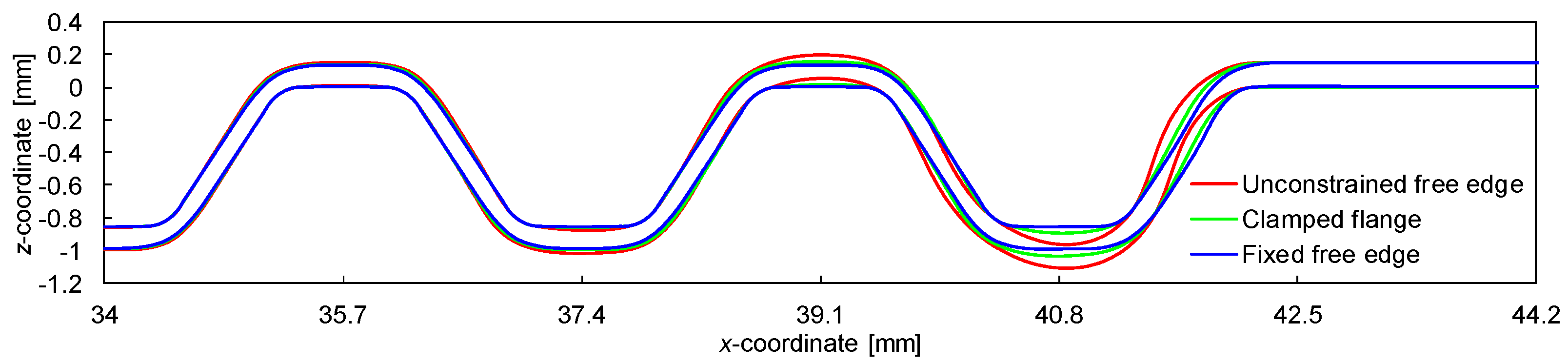
The predicted cross-section geometry of the two channels closest to the flange is presented in Figure 7, comparing the three boundary conditions applied to the flange. The shape of channel #1 (see Figure 6) is strongly affected by the boundary conditions adopted, as highlighted in Figure 7. Since the flange is completely free to slide (≈2.29 mm length) when the free edge is unconstrained while the blank-holder presents a fixed gap, the bottom of channel #1 is curved, while the fillet radii of the trapezoidal shape are larger. This induces differences in the height of the channels and consequent dimensional errors of the metallic BPP, which creates variations in the GDL assembly pressure distribution [52]. On the other hand, when the free edge of the flange is fixed in the x-direction, the geometry of all channels is identical, as shown in Figure 7. The application of a constant blank-holder force on the flange allows for a controlled sliding of the flange (≈1.16 mm length), providing a channel shape sited between the other two conditions.
The predicted thickness distribution on the BPP along the x-direction is presented in Figure 8, comparing the three different boundary conditions applied on the flange. The effect of the boundary conditions on the final thickness is negligible in the central region of the BPP, i.e., the three finite element models provide identical results for the channels away from the boundary. On the other hand, the predicted thickness distribution of the channels adjacent to the flange is strongly influenced by the boundary conditions adopted, as shown in Figure 8. The thinning is lower in this region of the BPP due to the sliding of the flange, particularly when the free edge of the flange is unconstrained. In contrast, the minimum value of thickness arises in the central region of the BPP, specifically in the fillet radii of the flow channels.
Since both the cross-section geometry of the flow channels (Figure 7) and the thickness distribution (Figure 8) present cyclic symmetry along the BPP width direction, particularly for channels away from the border, most of the studies are focused on a single channel [50]. Moreover, the maximum value of thinning occurs in the central region of the BPP, which dictates the formability analysis of the stamping process. Therefore, the analysis of a single channel is representative of the deformation occurring in the straight channel section of the BBPs. Hence, the sensitivity analysis carried out in the present study considers only a single channel in the finite element model, allowing reducing significantly the computational cost.
4.2. Single Channel
Due to symmetry conditions, only half-channel width is simulated under plane strain conditions, as shown in Figure 9. The displacement of the nodes located at the mid-width of the channel/rib is constrained in the x-direction, providing the cyclic symmetry conditions observed in the thickness distribution (Figure 8). Since the symmetry conditions are applied in both extremities of the channel, only the punch and the die are required in the numerical simulation (see Figure 9). Regardless of the tool dimensions tested during the sensitivity analysis, the half-distance between two consecutive channels d = 1.7 mm is fixed in all simulations (see Figure 5). The blank is discretized with 100 × 6 = 600 finite elements.
The reference values for the dimensions of the forming tools (punch and die) are presented in Table 2. The die is fixed, while the punch presents a prescribed displacement in the vertical direction, providing a maximum channel depth of h = 1.0 mm (see Figure 5b). In order to study the influence of the tools geometry on the formability, the channel/rib width, the punch/die radius, and the channel depth are selected as variable parameters in the present numerical model.
Effect of Tool Dimensions
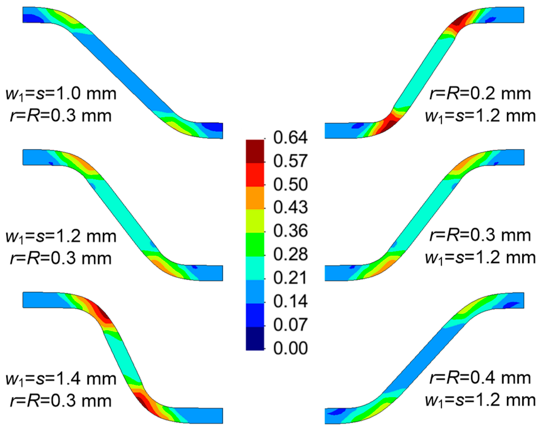
The channel/rib width is dictated by the punch/die width (assumed identical: w1 = s), while the fillet radius of the trapezoidal shape of the channel is defined by the fillet radius of the punch/die (assumed identical: r = R), as shown in Figure 5. The predicted geometry of the channel cross-section is presented in Figure 10, comparing three values of punch/die width, namely w1 = s = 1.0 mm, w1 = s = 1.2 mm, and w1 = s = 1.4 mm, and three values of punch/die fillet radius, namely r = R = 0.2 mm, r = R = 0.3 mm, and r = R = 0.4 mm. The maximum value of plastic strain (fillet zones) increases when the channel/rib width rises and when the fillet radius of the punch/die decreases. Both conditions lead to a decrease of the draft angle, as shown in Figure 10. The maximum value of equivalent plastic strain increases by approximately 40% from the narrow to the broad channel and increases by about 50% from the largest to the lower fillet radius.
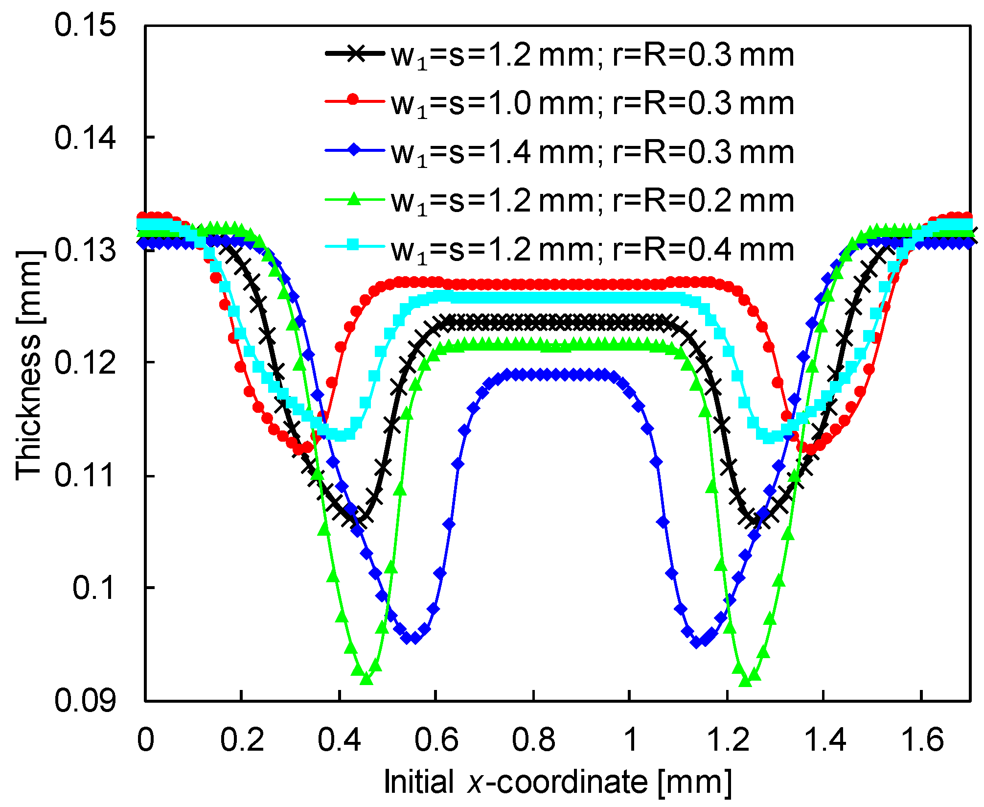
The predicted thickness distribution is presented in Figure 11 (half-channel), for the three different values of channel/rib width and the three values of punch/die fillet radius (h = 1.0 mm). The thickness is roughly constant in the wall, presenting a value slightly lower than the one measured in the rib/bottom of the channel. The minimum value of thickness occurs in the fillet zones of the flow channel, which is in agreement with the equivalent plastic strain distribution shown in Figure 10. Using the lower fillet radius, the minimum thickness is approximately 0.092 mm, while the adoption of the highest fillet radius leads to a minimum thickness of about 0.114 mm. Increasing the channel/rib width leads to a reduction of the minimum thickness, as shown in Figure 11. The comparison of the thickness distribution presented in Figure 11 with the thickness distribution in a BPP composed by 25 parallel channels (Figure 8) shows that the boundary conditions adopted in the single channel model allow representing accurately the process conditions.
The evolution of the maximum thinning in the channel is presented in Figure 12 for the three different values of channel/rib width and the three values of punch/die fillet radius. The increase of the maximum thinning is approximately linear for a punch displacement larger than 0.5 mm. However, considering either the lower fillet radius (r = R = 0.2 mm) or the broader channel (w1 = s = 1.4 mm), the thinning rate increases gradually after 0.8 mm of punch displacement (see Figure 12). This behaviour can indicate the occurrence of necking in the fillet radius of the flow channel, which is in agreement with the larger thickness strain predicted in this region (see Figure 11). For this channel geometry and considering the depth of 1.0 mm, the predicted maximum thinning is nearly 40%. Therefore, the formability of stamped BPPs is strongly affected by both the channel/rib width and the punch/die fillet radius.
Since the draft angle of the flow channel is dictated by the channel width w1, the dimension w2, and the channel depth (see Figure 5a), its value decreases with the punch displacement rising. The evolution of the draft angle with the punch displacement is presented in Figure 13, for the three different values of channel/rib width and the three values of punch/die fillet radius. For all channel geometries analysed, the decrease of the draft angle is approximately linear up to a channel depth of 0.5 mm However, the draft angle is always smaller for wider channel/rib and for smaller fillet radii of the punch/die, as shown in Figure 13 and Figure 10. In fact, considering a channel depth of 1.0 mm and r = R = 0.3 mm, the draft angles are about 51° and 91° in the broader and narrower channel, respectively.
The punch force required for the stamping of a single channel, assuming plane strain conditions, is presented in Figure 14, for three different values of channel/rib width and three different values of punch/die fillet radius. Since the thinning is significantly higher in wider channels with smaller fillet radii (see Figure 12), the required punch force is also considerably higher. Indeed, the punch force required for forming the wider channel is at least 40% higher than the one necessary for forming the narrowest channel, as shown in Figure 14. Besides, the slowest increase of the punch force after 0.7 mm of punch displacement indicates the onset of necking in the fillet radius of the flow channel (see Figure 11).
The last analysis considers different values for the channel and rib widths, i.e., w1 ≠ s, but the summation of them is always 2.4 mm in order to keep d = 1.7 mm (see Table 2). Assuming r = R = 0.3 mm and h = 1.0 mm, the final geometry of the channel cross-section is presented in Figure 15, comparing three different configurations. The predicted equivalent plastic strain distribution is identical in all channel configurations, because the draft angle is the same. Indeed, the flat zone in the bottom of the channel is reduced while the flat zone in the rib top is enlarged in the same proportion, as shown in Figure 15. Accordingly, this leads only to a shift in the thickness distribution, preserving the maximum thinning value during the punch force evolution.
5. U-bend Channel Section
In addition to the straight channel section, the BPP manufactured by forming is also composed by U-bend channel sections, as indicated in Figure 4. Indeed, the straight channel sections are connected between them by U-bend channel sections, leading to different flow field configurations (see Figure 2). Nevertheless, the modelling of the U-bend channel section requires the development of three-dimensional (3D) finite element models. This section contains the numerical analysis of this zone of the BPP, namely the effect of the tools geometry on the BPP deformed configuration.
5.1. Boundary Conditions
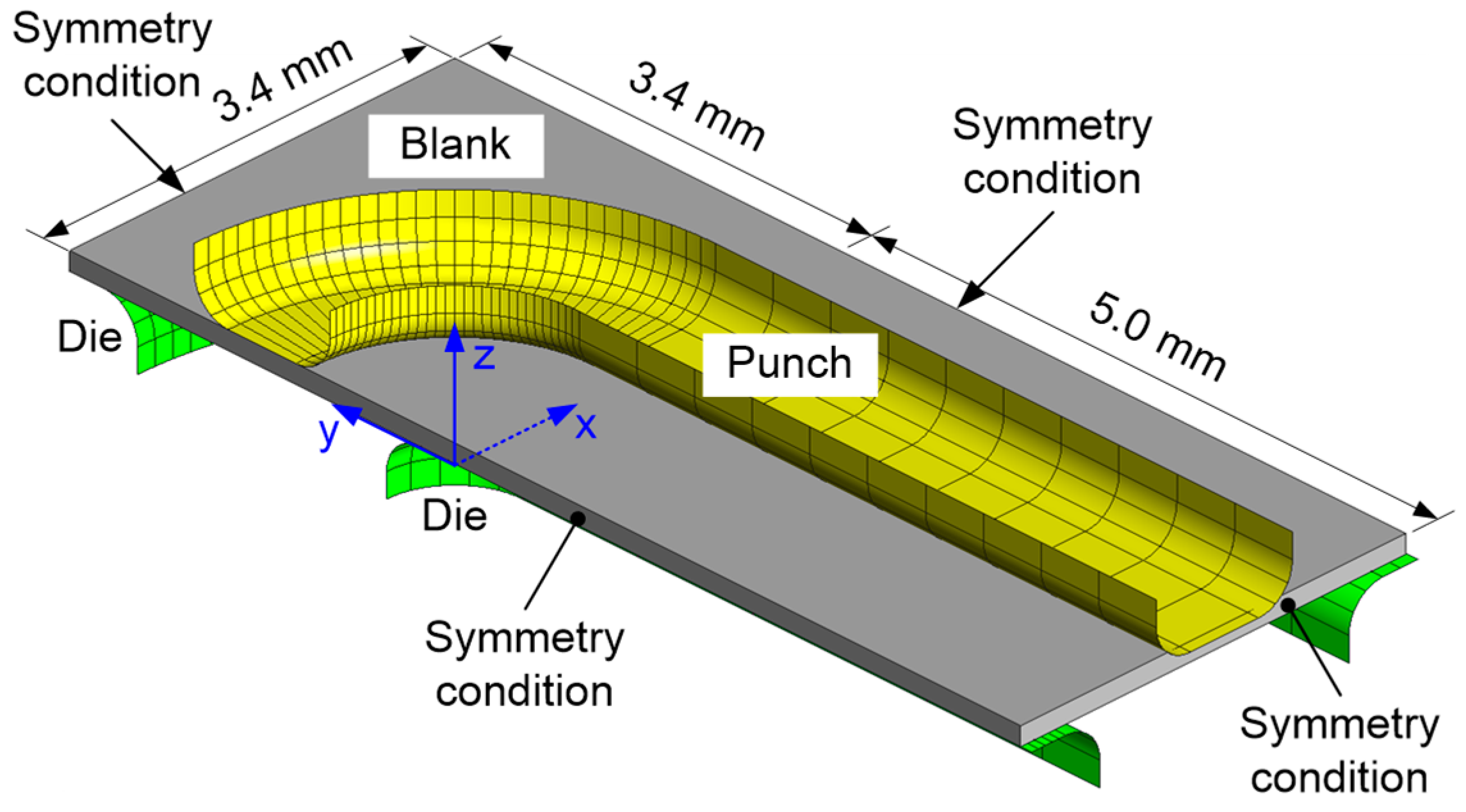
Besides the geometrical dimensions that describe the cross-section geometry of the channel, the U-bend section requires the definition of other dimensions. Anyway, revolving the cross-section geometry is the simplest way to create a U-bend channel section. Figure 16 presents the finite element model of the forming tools obtained by revolving the cross-section geometry (half-model), previously used as a reference in Section 4. The square blank (3.4 mm width) is discretized with 150 × 150 × 6 = 135,000 finite elements. Besides, symmetry conditions are applied in each of the four blank edges, in order to take into account the effect of the neighbouring channels, as illustrated in Figure 16.
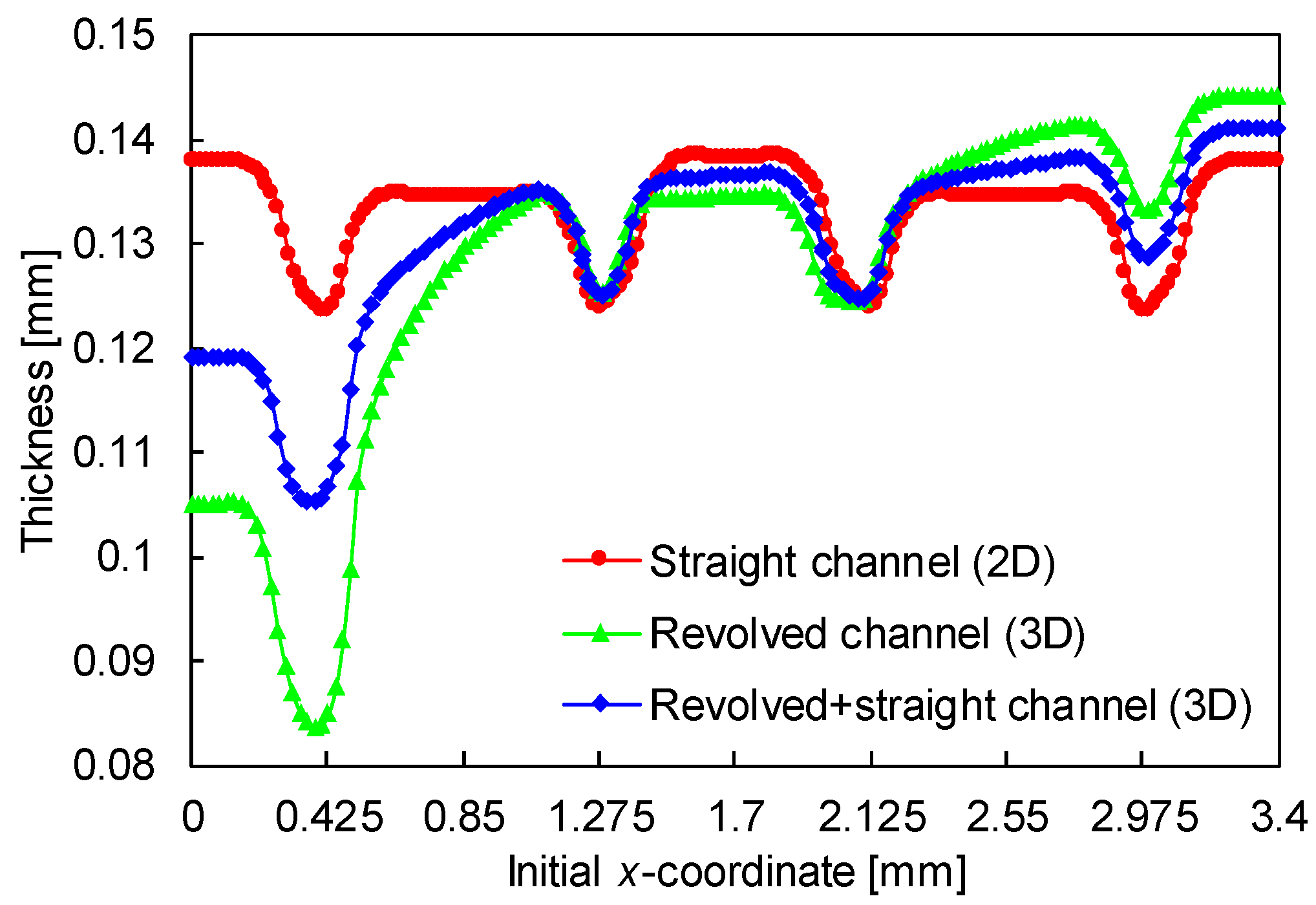
Considering the dimensions of the cross-section geometry listed in Table 2, the thickness distribution in the flow channel at y = 0 (see Figure 16) is presented in Figure 17. Figure 17 also shows the thickness distribution for a straight channel with the same geometrical dimensions, assuming plane strain conditions. Note that the 3D model considered has a total length of 3.4 mm, instead of the 1.7 mm (half) used in the previous section (see Figure 9). The thickness is substantially different from the one obtained with the finite element model previously presented in Section 4.2 (plane strain conditions). Since the thinning is considerably higher in the U-bend channel section than in the straight section, the channel depth (vertical displacement of the punch) is limited to 0.7 mm in this analysis. The thinning is significantly larger in the fillet radius of the channel close to the axis of revolution (near axisymmetric boundary conditions), as shown in Figure 17. On the other hand, the thicknesses predicted by both models are similar in the punch fillet radii. Besides, the computational time is higher than 10 h, when assuming 3D conditions, while when considering plane strain conditions, it is less than half-minute.
In order to assess the effect of the adopted boundary conditions on the deformation behaviour, the straight channel section is included in the revolved tool geometry. The finite element model of the forming tools is presented in Figure 18, using 5.0 mm as the length of the straight channel section. The blank is rectangular with dimensions 3.4 × 8.4 mm2 and discretized with 150 × 167 × 6 = 150,300 finite elements. The symmetry conditions are applied on all edges of the blank (see Figure 18), as shown in the previous model.
Using the finite element model presented in Figure 18 (labelled revolved + straight channel) with the dimensions listed in in Table 2, the predicted thickness distribution in the flow channel at y = 0 is presented in Figure 17. Since this numerical model is composed by the revolved tool geometry (Figure 16) and the extruded cross-section geometry (Figure 9), the predicted thickness is in-between the values obtained with the two previous models, as shown in Figure 17. Since the U-bend channel section is always connected to the straight channel (see Figure 4), the blank deformation is better predicted using this model, namely in the transition between the U-bend and the straight sections (y = 0). In fact, the maximum thinning occurs always in the region of the U-bend channel [49].
5.2. Bent Geometry
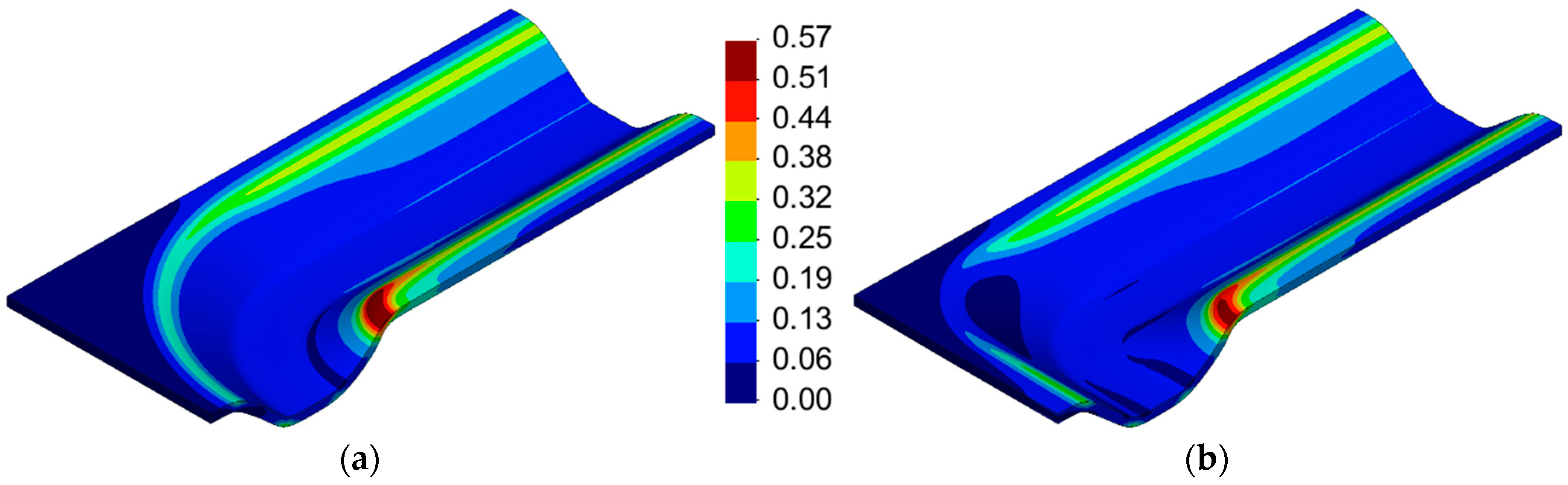
Considering the numerical model shown in Figure 18, the equivalent plastic strain distribution is presented in Figure 19a. The maximum value of equivalent plastic strain arises in the fillet radius of the die close to the axis of revolution. On the other hand, considering the fillet radius furthest away from the axis of revolution, the equivalent plastic strain increases from the U-bend to the straight channel section (see Figure 19a). This tool geometry leads to a cross-section profile (trapezoidal) which remains the same along the flow channel.
Since the lowest values of equivalent plastic strain (almost zero) are located in the exterior rib of the U-bend channel section (Figure 19a), the tool geometry (punch and die) was modified according to Figure 20. The revolved radius in the exterior rib of the die is 1.2 mm, while the revolution radius of the interior rib is kept identical (0.6 mm). The cross-section profile of the punch geometry is constant, while the clearance between the punch and die, measured along the diagonal direction, is equally distributed on both sides (see Figure 20). Thus, the U-bend channel section is composed of straight sections of the punch and die.
Considering the tool geometry presented in Figure 20, the equivalent plastic strain distribution plotted on the deformed configuration of the stamped channel is illustrated in Figure 19b. The area with larger values of equivalent plastic strain is reduced in comparison with the one obtained with the model given in Figure 18. Therefore, the formability of the stamped BPP is improved using the rounded bend tool geometry (Figure 20). Nevertheless, the cross-section profile of the flow channel is not constant along the entire U-bend section. The draft angle is larger in the diagonal direction (see Figure 19b), which results from the large clearance between the punch and the die in this zone of the channel, as highlighted in Figure 20b.
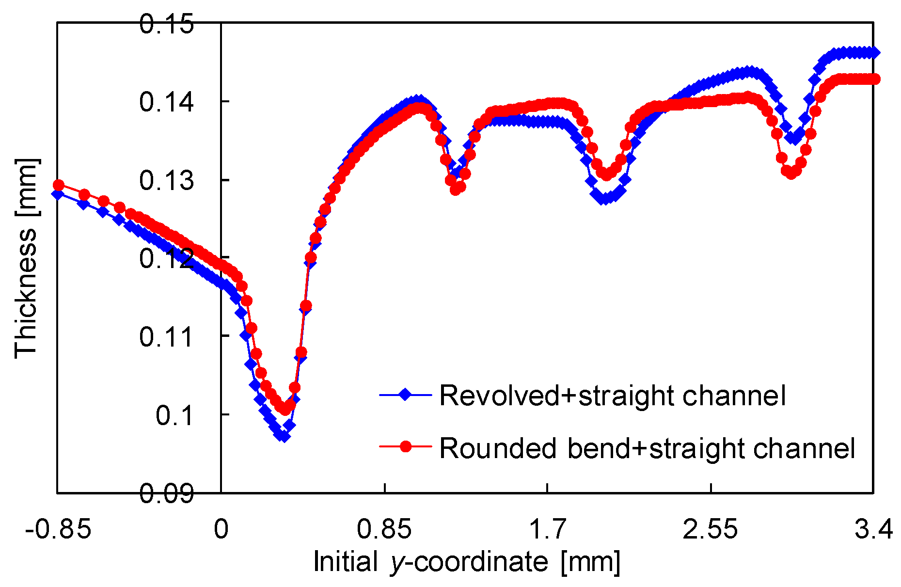
The final thickness distribution at x = 0 is presented in Figure 21, comparing the finite element models presented in Figure 18 and Figure 20. According to the axis system indicated in Figure 20, the negative values of y-coordinate correspond to the straight channel section. The minimum value of thickness occurs in the symmetry plane (x = 0) of the U-bend channel section (compare Figure 17 and Figure 21), specifically in the fillet radius of the die. However, the maximum thinning predicted with the tool geometry defined in Figure 20 (rounded bend) is lower than the one obtained using the model present in Figure 18. Besides, the tool geometry with rounded bend provides a flow channel with more uniform thickness, i.e., the final thickness ranges between 0.143 mm and 0.101 mm in this section, as shown in Figure 21. This improves the contact pressure distribution in the assembly due to the low dimensional error in terms of channel height of the metallic BPP [52].
5.3. Effect of Tool Dimensions
The rib width adjacent to the axis of revolution dictates the maximum value for the revolution radius of the cross-section geometry (see die in Figure 20b). Taking into account the results obtained assuming plane strain conditions (see Figure 11 and Figure 12), the thinning decreases with the reduction of the channel/rib width. Therefore, a new model was analysed, for which the rib width is increased to s = 1.4 mm in comparison with the tool geometry illustrated in Figure 20, while the other dimensions are kept constant (see in Table 2). In another model, the fillet radius R of the die is increased to R = 0.4 mm because, according to the straight channel results, the thinning decreases by increasing of the punch/die fillet radii (see Figure 11 and Figure 12). Finally, a model was built that takes into account both the rib width and the fillet radius of the die, which are increased to 1.6 mm and 0.5 mm, respectively.
The predicted thickness distribution in the stamped flow channel at x = 0 is presented in Figure 22, comparing the three die geometries previously described. The punch dimensions considered in the simulation are w1 = 1.2 mm and r = 0.3 mm, and the channel depth is h = 0.7 mm. Considering the U-bend channel section, the minimum value of thickness arises always in the fillet radius of the die closest to the axis of revolution, as shown in Figure 22. Indeed, the change of the die geometry, namely the rib width and the fillet radius, affects predominantly the thinning in this zone of the channel. The increase of both parameters leads to a reduction of the thinning. Considering the largest values for the rib width and fillet radius (s = 1.6 mm and R = 0.5 mm), the minimum thickness is about 0.11 mm, i.e., the maximum thinning is approximately 27% for h = 0.7 mm.
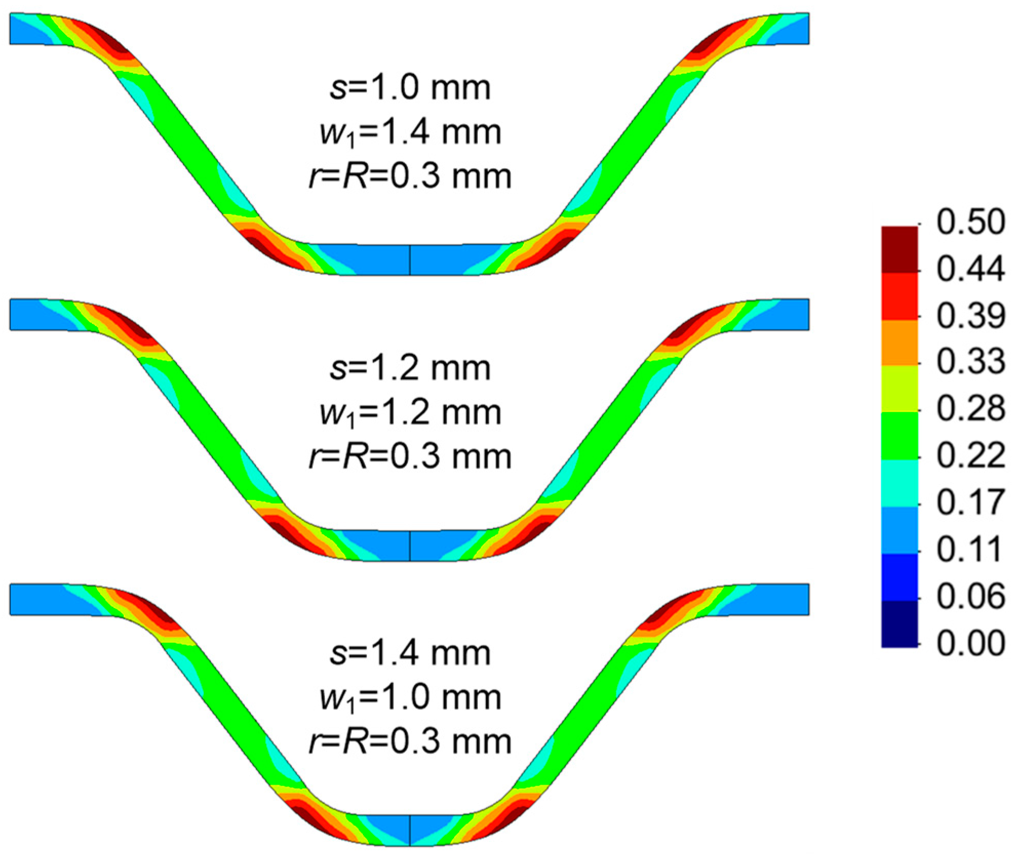
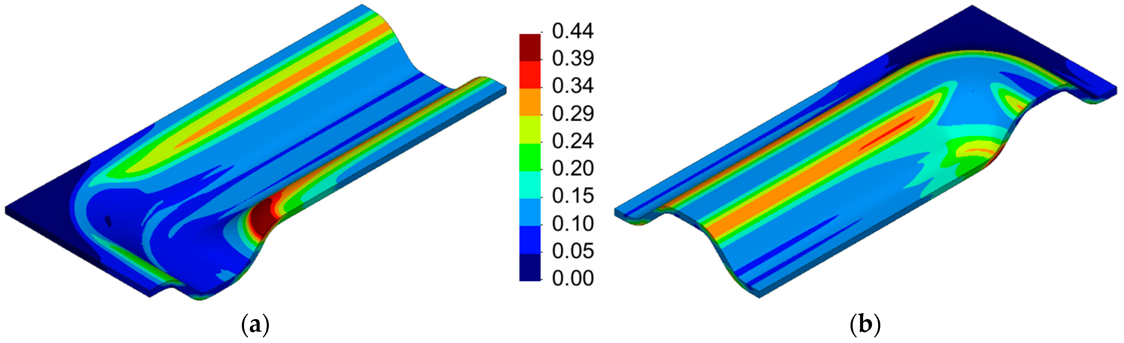
The equivalent plastic strain distribution is presented in Figure 23, comparing the three die geometries adopted in the finite element simulation. Although the distribution seems similar for all conditions, the maximum value of equivalent plastic strain is reduced from about 0.53 to approximately 0.43, which occurs always in the elliptic surface of the U-bend channel section (see Figure 23). Therefore, the increase of both the rib width and the fillet radius leads to a significant reduction of the equivalent plastic strain in this zone of the channel. Despite the modification of the die geometry, the flow channel cross-section areas are identical for all conditions. The obtained draft angle is approximately 95° in the trapezoidal shape of the channel cross-section.
The draft angle decreases when the punch width increases (Figure 13), due to the reduction of the gap between the punch and the die (see Figure 9b). The results obtained assuming plane strain conditions indicate that the channel width and the punch fillet radius have opposite effects on the thinning (see Figure 11). Thus, both the channel width and the fillet radius of the punch are increased. Considering the punch dimensions of w1 = 1.4 mm and r = 0.4 mm, the equivalent plastic strain distribution plotted on the deformed configuration of the channel is presented in Figure 24. The maximum value of equivalent plastic strain arises on the upper surface of the flow channel, specifically in the fillet radius of the die closest to the axis of revolution. On the other hand, the maximum value of equivalent plastic strain on the lower surface of the flow channel is located in the punch fillet radii (straight section), as shown in Figure 24b. In fact, regarding the straight channel section, the largest values of equivalent plastic strain occur always in the fillet radii, namely in the die fillet (upper surface) and in the punch fillet (lower surface).
The minor–major strain plot is presented in Figure 25, comparing the predictions obtained for the upper and lower surface of the flow channel. The strain paths of the points located on the upper surface are different from the one predicted for the lower surface of the channel, which is in accordance with the equivalent plastic strain gradient through the thickness (Figure 24). The deformation mode conditions in the BPP are predominantly between plane strain and equi-biaxial stretching, as shown in Figure 25. Nevertheless, the upper surface of the flow channel presents several points with nearly equi-biaxial stretching (large strain), which corresponds to the fillet radius of the die closest to the axis of revolution (see Figure 24a). On the other hand, the lower surface of the flow channel is mainly under plane strain conditions. Indeed, the largest value of major strain arises in that surface (see Figure 25), namely in the straight channel section.
The predicted thickness distribution is presented in Figure 26 for three different cross-sections of the stamped flow channel. The minimum value of thickness occurs in the fillet radius of the die (closest to the axis of revolution), specifically in the cross-section at x = 0. On the other hand, the predicted thickness distribution in the cross-section at y = −5 mm is identical to the one obtained considering plane strain conditions (straight channel section). Therefore, the formability analysis of this stamping process requires the study of the U-bend channel section, where the thinning is larger, as highlighted in Figure 26. Indeed, the maximum thinning (arising in the U-bend channel section) decreases by increasing the rib width, whereas assuming plane strain conditions (straight channel section) the increase of the rib width leads to increase of the thinning (see Figure 12).
6. Conclusions
This study presents the finite element analysis of the stamping process used in the manufacturing of metallic BPPs for PEM fuel cells. The effects of the geometrical dimensions of the forming tools on the formability and final thickness were discussed considering the stainless steel SS304 with a thickness of 0.15 mm. In order to reduce the computational cost of the simulation, only two representative zones of the BPP were studied, namely the straight and the U-bend channel sections.
Considering the finite element model composed by several parallel flow channels, the predicted geometry of each stamped channel varies according to its relative position, which results from the border effect. Both the height and the cross-section of the flow channel closest to the free edge are substantially different from the one adjacent to the symmetry condition. Nevertheless, the geometry of most flow channels was accurately predicted by the numerical model that considers half-channel width under plane strain conditions. Regarding the influence of the tools (punch and die) geometry on the formability, the amount of thinning decreases with the reduction of the channel/rib width and increase of the punch/die fillet radii. On the other hand, the predicted thinning increases as the channel depth increases.
The deformation mode changes gradually from plane strain in the straight channel section to biaxial strain in the U-bend section. Therefore, the accurate analysis of this zone requires the inclusion of a portion of the straight channel section in addition to the revolved cross-section geometry. In fact, the thinning is considerably overestimated when the model comprises only the revolved cross-section geometry. The maximum value of thinning occurs always in the U-bend channel section, namely in the fillet radius of the die closest to the axis of revolution. This zone presents the highest value of equivalent plastic strain, which increases by reducing both the rib width and the fillet radius.
The validation of the presented numerical model with experimental results will allow improving the reliability of the numerical results. The conclusions obtained from the numerical results should be attested using an experimental design of experiences.
Author Contributions
D.M.N. carried out the numerical simulations; J.L.A. developed software; D.M.N., M.C.O., and L.F.M. performed the formal analysis; D.M.N. wrote the original manuscript; all the authors participated in the writing, review and editing process.
Funding
This research was funded by the Portuguese Foundation for Science and Technology (FCT) under projects PTDC/EMS-TEC/0702/2014 (POCI-01-0145-FEDER-016779) and PTDC/EMS-TEC/6400/2014 (POCI-01-0145-FEDER-016876) by UE/FEDER through the program COMPETE 2020. The support under the project MATIS (CENTRO-01-0145-FEDER-000014) is also acknowledged.
Conflicts of Interest
The authors declare no conflicts of interest. The funders had no role in the design of the study; in the collection, analyses, or interpretation of data; in the writing of the manuscript, or in the decision to publish the results.
References
- Dunn, S. Hydrogen futures: Toward a sustainable energy system. Int. J. Hydrogen Energy 2002, 27, 235–264. [Google Scholar] [CrossRef]
- Wang, Y.; Chen, K.S.; Mishler, J.; Cho, S.C.; Adroher, X.C. A review of polymer electrolyte membrane fuel cells: Technology, applications, and needs on fundamental research. Appl. Energy 2011, 88, 981–1007. [Google Scholar] [CrossRef] [Green Version]
- Karimi, S.; Fraser, N.; Roberts, B.; Foulkes, F.R. A Review of Metallic Bipolar Plates for Proton Exchange Membrane Fuel Cells: Materials and Fabrication Methods. Adv. Mater. Sci. Eng. 2012, 2012, 1–22. [Google Scholar] [CrossRef] [Green Version]
- Wang, J. Barriers of scaling-up fuel cells: Cost, durability and reliability. Energy 2015, 80, 509–521. [Google Scholar] [CrossRef]
- DOE. Hydrogen and Fuel Cell Activities, Progress, and Plans; DOE: New York, NY, USA, 2009.
- Hermann, A.; Chaudhuri, T.; Spagnol, P. Bipolar plates for PEM fuel cells: A review. Int. J. Hydrogen Energy 2005, 30, 1297–1302. [Google Scholar] [CrossRef]
- Peng, L.; Yi, P.; Lai, X. Design and manufacturing of stainless steel bipolar plates for proton exchange membrane fuel cells. Int. J. Hydrogen Energy 2014, 39, 21127–21153. [Google Scholar] [CrossRef]
- Barbir, F. PEM Fuel Cells: Theory and Practice; Elsevier Academic: Cambridge, MA, USA, 2005. [Google Scholar]
- Taherian, R. A review of composite and metallic bipolar plates in proton exchange membrane fuel cell: Materials, fabrication, and material selection. J. Power Sources 2014, 265, 370–390. [Google Scholar] [CrossRef]
- Hu, Q.; Zhang, D.; Fu, H.; Huang, K. Investigation of stamping process of metallic bipolar plates in PEM fuel cell—Numerical simulation and experiments. Int. J. Hydrogen Energy 2014, 39, 13770–13776. [Google Scholar] [CrossRef]
- Peng, L.; Lai, X.; Liu, D.; Hu, P.; Ni, J. Flow channel shape optimum design for hydroformed metal bipolar plate in PEM fuel cell. J. Power Sources 2008, 178, 223–230. [Google Scholar] [CrossRef]
- Liu, Y.; Hua, L. Fabrication of metallic bipolar plate for proton exchange membrane fuel cells by rubber pad forming. J. Power Sources 2010, 195, 3529–3535. [Google Scholar] [CrossRef]
- Hung, J.C.; Chang, D.H.; Chuang, Y. The fabrication of high-aspect-ratio micro-flow channels on metallic bipolar plates using die-sinking micro-electrical discharge machining. J. Power Sources 2012, 198, 158–163. [Google Scholar] [CrossRef]
- Lee, S.J.; Lee, C.Y.; Yang, K.T.; Kuan, F.H.; Lai, P.H. Simulation and fabrication of micro-scaled flow channels for metallic bipolar plates by the electrochemical micro-machining process. J. Power Sources 2008, 185, 1115–1121. [Google Scholar] [CrossRef]
- Jin, C.; Jang, C.; Kang, C.; Jin, C.K.; Jang, C.H.; Kang, C.G. Vacuum Die Casting Process and Simulation for Manufacturing 0.8 mm-Thick Aluminum Plate with Four Maze Shapes. Metals 2015, 5, 192–205. [Google Scholar] [CrossRef] [Green Version]
- Antunes, R.A.; Oliveira, M.C.L.; Ett, G.; Ett, V. Corrosion of metal bipolar plates for PEM fuel cells: A review. Int. J. Hydrogen Energy 2010, 35, 3632–3647. [Google Scholar] [CrossRef]
- Koç, M.; Mahabunphachai, S. Feasibility investigations on a novel micro-manufacturing process for fabrication of fuel cell bipolar plates: Internal pressure-assisted embossing of micro-channels with in-die mechanical bonding. J. Power Sources 2007, 172, 725–733. [Google Scholar] [CrossRef]
- Mahabunphachai, S.; Cora, Ö.N.; Koç, M. Effect of manufacturing processes on formability and surface topography of proton exchange membrane fuel cell metallic bipolar plates. J. Power Sources 2010, 195, 5269–5277. [Google Scholar] [CrossRef]
- Kim, A.R.; Vinothkannan, M.; Yoo, D.J. Sulfonated fluorinated multi-block copolymer hybrid containing sulfonated (poly ether ether ketone) and graphene oxide: A ternary hybrid membrane architecture for electrolyte applications in proton exchange membrane fuel cells. J. Energy Chem. 2018, 27, 1247–1260. [Google Scholar] [CrossRef]
- Kim, A.R.; Park, C.J.; Vinothkannan, M.; Yoo, D.J. Sulfonated poly ether sulfone/heteropoly acid composite membranes as electrolytes for the improved power generation of proton exchange membrane fuel cells. Compos. Part B Eng. 2018, 155, 272–281. [Google Scholar] [CrossRef]
- André, J.; Antoni, L.; Petit, J.P.; De Vito, E.; Montani, A. Electrical contact resistance between stainless steel bipolar plate and carbon felt in PEFC: A comprehensive study. Int. J. Hydrogen Energy 2009, 34, 3125–3133. [Google Scholar] [CrossRef]
- Ge, J.; Higier, A.; Liu, H. Effect of gas diffusion layer compression on PEM fuel cell performance. J. Power Sources 2006, 159, 922–927. [Google Scholar] [CrossRef]
- Wlodarczyk, R.; Zasada, D.; Morel, S.; Kacprzak, A. A comparison of nickel coated and uncoated sintered stainless steel used as bipolar plates in low-temperature fuel cells. Int. J. Hydrogen Energy 2016, 41, 17644–17651. [Google Scholar] [CrossRef]
- Hung, Y.; EL-Khatib, K.M.; Tawfik, H. Corrosion-resistant lightweight metallic bipolar plates for PEM fuel cells. J. Appl. Electrochem. 2005, 35, 445–447. [Google Scholar] [CrossRef] [Green Version]
- Jin, C.K.; Koo, J.Y.; Kang, C.G. Fabrication of stainless steel bipolar plates for fuel cells using dynamic loads for the stamping process and performance evaluation of a single cell. Int. J. Hydrogen Energy 2014, 39, 21461–21469. [Google Scholar] [CrossRef]
- Park, W.T.; Jin, C.K.; Kang, C.G. Improving channel depth of stainless steel bipolar plate in fuel cell using process parameters of stamping. Int. J. Adv. Manuf. Technol. 2016, 87, 1677–1684. [Google Scholar] [CrossRef]
- Bong, H.J.; Lee, J.; Kim, J.H.; Barlat, F.; Lee, M.G. Two-stage forming approach for manufacturing ferritic stainless steel bipolar plates in PEM fuel cell: Experiments and numerical simulations. Int. J. Hydrogen Energy 2017, 42, 6965–6977. [Google Scholar] [CrossRef]
- Afshari, E.; Mosharaf-Dehkordi, M.; Rajabian, H. An investigation of the PEM fuel cells performance with partially restricted cathode flow channels and metal foam as a flow distributor. Energy 2017, 118, 705–715. [Google Scholar] [CrossRef]
- Wang, J. Theory and practice of flow field designs for fuel cell scaling-up: A critical review. Appl. Energy 2015, 157, 640–663. [Google Scholar] [CrossRef]
- Dhahad, H.A.; Alawee, W.H.; Hassan, A.K. Experimental study of the effect of flow field design to PEM fuel cells performance. Renew. Energy Focus 2019, 30, 71–77. [Google Scholar] [CrossRef]
- Kahraman, H.; Orhan, M.F. Flow field bipolar plates in a proton exchange membrane fuel cell: Analysis & modeling. Energy Convers. Manag. 2017, 133, 363–384. [Google Scholar]
- Arvay, A.; French, J.; Wang, J.C.; Peng, X.H.; Kannan, A.M. Nature inspired flow field designs for proton exchange membrane fuel cell. Int. J. Hydrogen Energy 2013, 38, 3717–3726. [Google Scholar] [CrossRef]
- Guo, N.; Leu, M.C.; Koylu, U.O. Bio-inspired flow field designs for polymer electrolyte membrane fuel cells. Int. J. Hydrogen Energy 2014, 39, 21185–21195. [Google Scholar] [CrossRef]
- Shimpalee, S.; Van Zee, J.W. Numerical studies on rib & channel dimension of flow-field on PEMFC performance. Int. J. Hydrogen Energy 2007, 32, 842–856. [Google Scholar]
- Hontañón, E.; Escudero, M.J.; Bautista, C.; García-Ybarra, P.L.; Daza, L. Optimisation of flow-field in polymer electrolyte membrane fuel cells using computational fluid dynamics techniques. J. Power Sources 2000, 86, 363–368. [Google Scholar] [CrossRef]
- Manso, A.P.; Marzo, F.F.; Mujika, M.G.; Barranco, J.; Lorenzo, A. Numerical analysis of the influence of the channel cross-section aspect ratio on the performance of a PEM fuel cell with serpentine flow field design. Int. J. Hydrogen Energy 2011, 36, 6795–6808. [Google Scholar] [CrossRef]
- Hu, P.; Peng, L.; Zhang, W.; Lai, X. Optimization design of slotted-interdigitated channel for stamped thin metal bipolar plate in proton exchange membrane fuel cell. J. Power Sources 2009, 187, 407–414. [Google Scholar] [CrossRef]
- Xu, Y.; Peng, L.; Yi, P.; Lai, X. Analysis of the flow distribution for thin stamped bipolar plates with tapered channel shape. Int. J. Hydrogen Energy 2016, 41, 5084–5095. [Google Scholar] [CrossRef]
- Menezes, L.F.; Teodosiu, C. Three-dimensional numerical simulation of the deep-drawing process using solid finite elements. J. Mater. Process. Technol. 2000, 97, 100–106. [Google Scholar] [CrossRef] [Green Version]
- Oliveira, M.C.; Alves, J.L.; Menezes, L.F. Algorithms and Strategies for Treatment of Large Deformation Frictional Contact in the Numerical Simulation of Deep Drawing Process. Arch. Comput. Methods Eng. 2008, 15, 113–162. [Google Scholar] [CrossRef] [Green Version]
- Menezes, L.F.; Neto, D.M.; Oliveira, M.C.; Alves, J.L. Improving Computational Performance through HPC Techniques: Case study using DD3IMP in-house code. AIP Conf. Proc. 2011, 1353, 1220–1225. [Google Scholar]
- Pham, C.H.; Thuillier, S.; Manach, P.Y. Prediction of flow stress and surface roughness of stainless steel sheets considering an inhomogeneous microstructure. Mater. Sci. Eng. A 2016, 678, 377–388. [Google Scholar] [CrossRef]
- Pham, C.H.; Thuillier, S.; Manach, P.Y. Mechanical Properties Involved in the Micro-forming of Ultra-thin Stainless Steel Sheets. Metall. Mater. Trans. A 2015, 46, 3502–3515. [Google Scholar] [CrossRef]
- Raj, A.K. Formability: Metastable Austenitic Stainless Steels; Lulu Press: Morrisville, NC, USA, 2015. [Google Scholar]
- Neto, D.M.; Oliveira, M.C.; Menezes, L.F.; Alves, J.L. Applying Nagata patches to smooth discretized surfaces used in 3D frictional contact problems. Comput. Methods Appl. Mech. Eng. 2014, 271, 296–320. [Google Scholar] [CrossRef]
- Neto, D.M.; Oliveira, M.C.; Menezes, L.F.; Alves, J.L. Nagata patch interpolation using surface normal vectors evaluated from the IGES file. Finite Elem. Anal. Des. 2013, 72, 35–46. [Google Scholar] [CrossRef]
- Hughes, T.J.R. Generalization of selective integration procedures to anisotropic and nonlinear media. Int. J. Numer. Methods Eng. 1980, 15, 1413–1418. [Google Scholar] [CrossRef]
- Li, K.P.; Carden, W.P.; Wagoner, R.H. Simulation of springback. Int. J. Mech. Sci. 2002, 44, 103–122. [Google Scholar] [CrossRef]
- Peng, L.; Liu, D.; Hu, P.; Lai, X.; Ni, J. Fabrication of Metallic Bipolar Plates for Proton Exchange Membrane Fuel Cell by Flexible Forming Process-Numerical Simulations and Experiments. J. Fuel Cell Sci. Technol. 2010, 7, 031009. [Google Scholar] [CrossRef]
- Xu, S.; Li, K.; Wei, Y.; Jiang, W. Numerical investigation of formed residual stresses and the thickness of stainless steel bipolar plate in PEMFC. Int. J. Hydrogen Energy 2016, 41, 6855–6863. [Google Scholar] [CrossRef]
- Koo, J.Y.; Jeon, Y.P.; Kang, C.G. Effect of stamping load variation on deformation behaviour of stainless steel thin plate with microchannel. Proc. Inst. Mech. Eng. Part B J. Eng. Manuf. 2013, 227, 1121–1128. [Google Scholar] [CrossRef]
- Liu, D.; Peng, L.; Lai, X. Effect of dimensional error of metallic bipolar plate on the GDL pressure distribution in the PEM fuel cell. Int. J. Hydrogen Energy 2009, 34, 990–997. [Google Scholar] [CrossRef]
Figure 1.
Schematic representation of a proton exchange membrane fuel cell composed by the bipolar plates (BPPs) and the membrane electrode assembly (not to scale).
Figure 1.
Schematic representation of a proton exchange membrane fuel cell composed by the bipolar plates (BPPs) and the membrane electrode assembly (not to scale).

Figure 2.
Scheme of typical flow field configurations: (a) straight parallel; (b) interdigitated; (c) pin-type; (d) spiral; (e) single-channel serpentine; (f) multiple-channel (triple) serpentine.
Figure 2.
Scheme of typical flow field configurations: (a) straight parallel; (b) interdigitated; (c) pin-type; (d) spiral; (e) single-channel serpentine; (f) multiple-channel (triple) serpentine.

Figure 3.
Comparison between experimental and numerical stress–strain curves from the uniaxial tensile test in the rolling direction (stainless steel SS304).
Figure 3.
Comparison between experimental and numerical stress–strain curves from the uniaxial tensile test in the rolling direction (stainless steel SS304).

Figure 4.
Example of a bipolar plate manufactured by forming, indicating both the straight and the U-bend channel sections: a BPP with an interdigitated flow field for reactant gases and a serpentine flow field for the coolant fluid on the opposite side [49].
Figure 4.
Example of a bipolar plate manufactured by forming, indicating both the straight and the U-bend channel sections: a BPP with an interdigitated flow field for reactant gases and a serpentine flow field for the coolant fluid on the opposite side [49].

Figure 5.
Stamping process used to manufacture BPPs: (a) cross-section of the obtained trapezoidal channel with key dimensions; (b) cross-section of the tools (punch and die including the main dimensions).
Figure 5.
Stamping process used to manufacture BPPs: (a) cross-section of the obtained trapezoidal channel with key dimensions; (b) cross-section of the tools (punch and die including the main dimensions).

Figure 6.
Finite element model (plane strain conditions and half width) of a stamped BPP composed by 25 parallel channels: (a) initial position; (b) final configuration.
Figure 6.
Finite element model (plane strain conditions and half width) of a stamped BPP composed by 25 parallel channels: (a) initial position; (b) final configuration.

Figure 7.
Cross-section of the BPP (2 channels closest to the flange) using three different boundary conditions in the flange region and considering plane strain conditions.
Figure 7.
Cross-section of the BPP (2 channels closest to the flange) using three different boundary conditions in the flange region and considering plane strain conditions.

Figure 8.
Thickness distribution on the BPP along the x-direction using three different boundary conditions in the flange region and considering plane strain conditions.
Figure 8.
Thickness distribution on the BPP along the x-direction using three different boundary conditions in the flange region and considering plane strain conditions.

Figure 9.
Finite element model of the stamping process (half-channel) assuming plane strain conditions: (a) initial configuration; (b) final configuration.
Figure 9.
Finite element model of the stamping process (half-channel) assuming plane strain conditions: (a) initial configuration; (b) final configuration.

Figure 10.
Equivalent plastic strain distribution plotted on the deformed configuration of the channel for three values of channel/rib width (left side) and for three values of punch/die fillet radius (right side) and h = 1.0 mm.
Figure 10.
Equivalent plastic strain distribution plotted on the deformed configuration of the channel for three values of channel/rib width (left side) and for three values of punch/die fillet radius (right side) and h = 1.0 mm.

Figure 11.
Thickness distribution in half-channel for three values of channel/rib width and three values of punch/die fillet radius (h = 1.0 mm).
Figure 11.
Thickness distribution in half-channel for three values of channel/rib width and three values of punch/die fillet radius (h = 1.0 mm).

Figure 12.
Evolution of the maximum thinning in the channel with the punch displacement for three values of channel/rib width and three values of punch/die fillet radius (plane strain conditions).
Figure 12.
Evolution of the maximum thinning in the channel with the punch displacement for three values of channel/rib width and three values of punch/die fillet radius (plane strain conditions).

Figure 13.
Draft angle evolution obtained for three values of channel/rib width and three values of punch/die fillet radius (plane strain conditions).
Figure 13.
Draft angle evolution obtained for three values of channel/rib width and three values of punch/die fillet radius (plane strain conditions).

Figure 14.
Punch force evolution obtained for three values of channel/rib width and three values of punch/die fillet radius (plane strain conditions).
Figure 14.
Punch force evolution obtained for three values of channel/rib width and three values of punch/die fillet radius (plane strain conditions).

Figure 15.
Equivalent plastic strain distribution plotted on the deformed configuration of the channel for three different values of channel width and rib width (plane strain conditions) and h = 1.0 mm.
Figure 15.
Equivalent plastic strain distribution plotted on the deformed configuration of the channel for three different values of channel width and rib width (plane strain conditions) and h = 1.0 mm.

Figure 16.
Finite element model adopted to simulate the stamping of the U-bend channel section (revolved tool geometry).
Figure 16.
Finite element model adopted to simulate the stamping of the U-bend channel section (revolved tool geometry).

Figure 17.
Thickness distribution in a single channel at y = 0 for the three different models. The parameters are w1 = s = 1.2 mm, r = R = 0.3 mm, and h = 0.7 mm.
Figure 17.
Thickness distribution in a single channel at y = 0 for the three different models. The parameters are w1 = s = 1.2 mm, r = R = 0.3 mm, and h = 0.7 mm.

Figure 18.
Finite element model adopted to simulate the stamping of the U-bend channel section (revolved tool geometry with a straight section).
Figure 18.
Finite element model adopted to simulate the stamping of the U-bend channel section (revolved tool geometry with a straight section).

Figure 19.
Equivalent plastic strain distribution plotted on the deformed configuration of the channel: (a) revolved tool geometry in the U-bend channel section; (b) rounded bend in the U-bend channel section.
Figure 19.
Equivalent plastic strain distribution plotted on the deformed configuration of the channel: (a) revolved tool geometry in the U-bend channel section; (b) rounded bend in the U-bend channel section.

Figure 20.
Finite element model of the tools adopted in the stamping of the U-bend channel section (rounded bend): (a) lateral view; (b) top view.
Figure 20.
Finite element model of the tools adopted in the stamping of the U-bend channel section (rounded bend): (a) lateral view; (b) top view.

Figure 21.
Thickness distribution in a single channel at x = 0, for the two different models. The parameters are w1 = s = 1.2 mm, r = R = 0.3 mm, and h = 0.7 mm.
Figure 21.
Thickness distribution in a single channel at x = 0, for the two different models. The parameters are w1 = s = 1.2 mm, r = R = 0.3 mm, and h = 0.7 mm.

Figure 22.
Thickness distribution in the flow channel at x = 0, comparing three different geometries of the die. The parameters are w1 = 1.2 mm, r = 0.3 mm, and h = 0.7 mm.
Figure 22.
Thickness distribution in the flow channel at x = 0, comparing three different geometries of the die. The parameters are w1 = 1.2 mm, r = 0.3 mm, and h = 0.7 mm.

Figure 23.
Equivalent plastic strain distribution plotted on the deformed configuration of the channel for different die dimensions: (a) s = 1.4 mm and R = 0.3 mm; (b) s = 1.4 mm and R = 0.4 mm; (c) s = 1.6 mm and R = 0.5 mm. The other parameters are w1 = 1.2 mm, r = 0.3 mm, and h = 0.7 mm.
Figure 23.
Equivalent plastic strain distribution plotted on the deformed configuration of the channel for different die dimensions: (a) s = 1.4 mm and R = 0.3 mm; (b) s = 1.4 mm and R = 0.4 mm; (c) s = 1.6 mm and R = 0.5 mm. The other parameters are w1 = 1.2 mm, r = 0.3 mm, and h = 0.7 mm.

Figure 24.
Equivalent plastic strain distribution plotted on the deformed configuration of the channel parameters considering w1 = 1.4 mm, s = 1.6 mm, r = 0.4 mm, R = 0.5 mm, and h = 0.7 mm: (a) upper surface of the flow channel; (b) lower surface of the flow channel.
Figure 24.
Equivalent plastic strain distribution plotted on the deformed configuration of the channel parameters considering w1 = 1.4 mm, s = 1.6 mm, r = 0.4 mm, R = 0.5 mm, and h = 0.7 mm: (a) upper surface of the flow channel; (b) lower surface of the flow channel.

Figure 25.
Minor–major strain plots for both surfaces of the channel (upper and lower) considering w1 = 1.4 mm, s = 1.6 mm, r = 0.4 mm, R = 0.5 mm, and h = 0.7 mm.
Figure 25.
Minor–major strain plots for both surfaces of the channel (upper and lower) considering w1 = 1.4 mm, s = 1.6 mm, r = 0.4 mm, R = 0.5 mm, and h = 0.7 mm.

Figure 26.
Thickness distribution in three different localizations of the flow channel considering w1 = 1.4 mm, s = 1.6 mm, r = 0.4 mm, R = 0.5 mm, and h = 0.7 mm.
Figure 26.
Thickness distribution in three different localizations of the flow channel considering w1 = 1.4 mm, s = 1.6 mm, r = 0.4 mm, R = 0.5 mm, and h = 0.7 mm.


Table 1.
Material parameters used in the isotropic Swift hardening law to describe the SS304 stainless steel.
Table 1.
Material parameters used in the isotropic Swift hardening law to describe the SS304 stainless steel.
| Y0 (MPa) | K (MPa) | n |
|---|---|---|
| 255.02 | 1481.84 | 0.508 |
Table 2.
Reference values for the main dimensions of the forming tools (punch and die) adopted in the analysis of the straight channel section.
Table 2.
Reference values for the main dimensions of the forming tools (punch and die) adopted in the analysis of the straight channel section.
| w1 | w2 | S | r | R | d= (w2 + s)/2 |
|---|---|---|---|---|---|
| 1.2 mm | 2.2 mm | 1.2 mm | 0.3 mm | 0.3 mm | 1.7 mm |
© 2019 by the authors. Licensee MDPI, Basel, Switzerland. This article is an open access article distributed under the terms and conditions of the Creative Commons Attribution (CC BY) license (http://creativecommons.org/licenses/by/4.0/).
Share and Cite
MDPI and ACS Style
Neto, D.M.; Oliveira, M.C.; Alves, J.L.; Menezes, L.F. Numerical Study on the Formability of Metallic Bipolar Plates for Proton Exchange Membrane (PEM) Fuel Cells. Metals 2019, 9, 810. https://doi.org/10.3390/met9070810
AMA Style
Neto DM, Oliveira MC, Alves JL, Menezes LF. Numerical Study on the Formability of Metallic Bipolar Plates for Proton Exchange Membrane (PEM) Fuel Cells. Metals. 2019; 9(7):810. https://doi.org/10.3390/met9070810
Chicago/Turabian StyleNeto, Diogo M., Marta C. Oliveira, José L. Alves, and Luís F. Menezes. 2019. "Numerical Study on the Formability of Metallic Bipolar Plates for Proton Exchange Membrane (PEM) Fuel Cells" Metals 9, no. 7: 810. https://doi.org/10.3390/met9070810
Note that from the first issue of 2016, this journal uses article numbers instead of page numbers. See further details here.