Carbide Precipitation, Dissolution, and Coarsening in G18CrMo2–6 Steel


1
School of Materials Science and Engineering, Taiyuan University of Science and Technology, Taiyuan 030024, China
2
Shanxi Key Laboratory of Metal Forming Theory and Technology, Taiyuan 030024, China
*
Author to whom correspondence should be addressed.
Metals 2019, 9(9), 916; https://doi.org/10.3390/met9090916
Submission received: 25 July 2019
/
Revised: 18 August 2019
/
Accepted: 19 August 2019
/
Published: 22 August 2019
(This article belongs to the Special Issue High-Strength Low-Alloy Steels)
Abstract
:The precipitation, dissolution, and coarsening of different carbides at 680 °C in G18CrMo2–6 steel was investigated experimentally combined with Jmatpro simulation. The G18CrMo2–6 steel was normalized at 940 °C, followed by tempering at different times at a constant temperature of 680 °C. During the tempering process, there are mainly two kinds of carbide, namely M3C and M23C6. Through characterization of microstructural evolution, thermodynamic calculation, and kinetic simulation, it was observed that during the tempering process, the stable M23C6 carbide was growing, whereas the metastable M3C carbide was disappearing. At the end, the M3C carbide was dissolved and the M23C6 carbide was in equilibrium with the matrix.
1. Introduction
Low-alloy chromium-containing heat-resistant steel is widely used in the power generation industry of pressure vessels and superheater tubes due to its excellent mechanical properties, good weldability, and good creep properties at high temperatures. To increase the efficiency of steam turbine equipment, these steels have been improved to provide higher creep strength. The creep strength of these steels usually decreases rapidly during long-term use because the microstructure becomes unstable at high temperatures. The coarsening of carbide is detrimental for creep strength. Therefore, it is very important to carefully investigate the evolution behavior of carbide. Actually, the alloying element molybdenum is usually added to these steels to reduce the segregation of the impurity elements at the grain boundaries and to cause solid solution strengthening. In addition, the alloying element vanadium is added to form fine grain strengthening and precipitation hardening.
Many authors have studied the crystal structure, chemical composition, and distribution of carbides in these steels. The evolution and distribution of carbides during heat treatment and service are the main factors affecting the creep resistance of such low-alloy steels. Tsai et al. [1] and Tsai and Yang [2] found that in the heat affected zone of 2.25Cr1Mo steels, M2C, M3C, M7C3, and M23C6 carbides precipitated at different times during tempering at 700 °C, and the final equilibrium precipitate is M23C6 carbide. Yang and Kim [3] studied the mechanical properties and thermal embrittlement of 2.25Cr1Mo steel after a long period of high-temperature aging treatment and observed that some carbides were transformed during that treatment, leading to thermal embrittlement. Janovec et al. [4,5] found that the composition of steel, tempering temperature, and tempering holding time had an influence on the composition, type, and distribution position of the precipitate carbides. Tao et al. [6] investigated the carbide evolution of 2.25Cr1Mo weld metal during tempering at 700 °C and found that the precipitation strengthening effect was weakened due to carbide coarsening, and then the hardness of the tempered sample decreased. Jiang et al. [7,8] studied the evolution of 2.25Cr1Mo0.25V during tempering at 700 °C, and found that the decomposition of the martensite–austenite island and the coarsening of the MC carbide led to a decrease in material strength and an increase in ductile–brittle transition temperature (DBTT).
A method for simulating diffusion reactions in a multi-component system was developed by Ågren [9,10], which can be used to calculate nucleation, dissolution, and coarsening, etc. It is assumed that there is no difference in chemical composition and chemical potential at the interface between the matrix and the carbide. In this case, the problem is a simple diffusion problem. Therefore, the concentration of the components at the interface can be estimated by thermodynamic calculation. Based on the methods, many researchers [11,12,13,14,15,16,17,18] have studied the evolution of precipitated phases in steel.
Related research work has been done to study the influence of alloying elements on precipitation behavior. The growth and coarsening of M23C6 carbide was the subject of many related investigations. However, only a few investigations focus on the dissolution of carbides. The dissolution, precipitation, and growth of carbides often occur at the same time. Simultaneously simulating the evolution of several precipitates can reduce the simulation error. The aim of this paper was to investigate the precipitation, coarsening, and possible dissolution of carbides in matrix at 680 °C, which is a normal tempering temperature for low-alloy chromium-containing heat-resistant steels.
2. Experimental Section
2.1. Material Preparation and Heat Treatments
G18CrMo2–6 steel was melted into an ingot of 20 kg using a vacuum induction furnace (Wanfeng Inc., Luoyang, China). The chemical composition (wt%) of G18CrMo2–6 steel is listed in Table 1. Jmatpro calculation provides useful guidelines for the evolution and volume fractions of phases in G18CrMo2–6 steel. The thermodynamic calculations were carried out under equilibrium conditions and the kinetic calculations were carried out at a temperature of 680 °C. The steel was diffusion annealed at 1200 °C for 10 h and then air cooled to room temperature. Afterward, 10 × 10 × 10 mm3 blocks were cut down from the diffusion-annealed material using a DK7740 wire cutting machine (Star Peak Inc., Taizhou, China), and then the specimen was placed in a glass tube filled with argon for subsequent heat treatments. All specimens were cooled in a furnace after being heated at 940 °C for 2 h to simulate the cooling rate of the actual production process. Then, all samples were tempered at 680 °C; this tempering temperature is commonly used to make large castings and forgings. In order to study the evolution of the microstructure and precipitates during tempering, the tempering time varied from 0 to 1000 h.
2.2. Sample Preparation and Characterization
After the heat treatments, metallographic specimens were ground, polished, and then etched with 4 vol % nital liquid for 5–10 s for microstructure observation. An AXIOVERT 200MAT Optical microscope (OM) (Zeiss, Oberkochen, Germany), an S-3400N scanning electron microscope (SEM) (JEOL Ltd, Tokyo, Japan), and a transmission electron microscope (TEM) (Oxford Instruments, Abingdon UK) were used to observe the microstructure. Thin foil samples for TEM were prepared by mechanical polishing, and twin jet electro-polishing was performed with a 10% perchloric acid-glacial acetic acid solution with 20 V voltage at −20 °C. The composition of carbides in the samples was detected by an energy-dispersive X-ray (EDX) analyzer (JEOL Ltd, Tokyo, Japan) which was attached to the SEM and TEM. The carbide powder obtained by electrolytic extraction method was identified by X-ray diffraction (XRD) to investigate the carbides’ evolution during tempering.
3. Results and Discussion
3.1. Phase Diagram Calculation
The equilibrium phase diagram of G18CrMo2–6 steel is calculated as shown in Figure 1. The abscissa is the temperature and the ordinate is the weight fraction of the equilibrium phase. According to the equilibrium phase diagram, there is only one precipitate phase of M23C6 (M = Fe, Cr, Mn, Mo) at 680 °C. The results of the phase diagram calculation are inconsistent with the experimental results reported in the literature [6,19]. This is mainly because the equilibrium phase diagram is only the result of thermodynamic calculations, and the calculation process ignores the effects of kinetics. In addition, the state of the experimental materials is metastable under normal conditions.
3.2. Characterization of Microstructural Evolution
3.2.1. Characterization of Microstructural Evolution by OM
Figure 2 presents the metallographic photographs of the samples after tempering at 680 °C for different tempering times. After the above heat treatment, it can be seen that the microstructure of the samples is composed of two phases of ferrite and bainite; the white area is ferrite and the gray and dark areas are bainite. With the extension of tempering time, the participation of white parts on the matrix increased gradually, and the color difference between ferrite and bainite decreased. It seems that the participation of ferrite increased and the participation of bainite decreased. However, tempering heat treatment cannot change the crystal structure of ferrite and bainite in the matrix. This may be the illusion caused by the evolution of the precipitates on the bainite matrix during tempering. However, the morphology, distribution, and type of carbides may change during tempering.
3.2.2. Characterization of Microstructural Evolution by SEM and XRD
In the initial stages of tempering (Figure 3a,b), many long rod-shaped precipitates in the bainite grains can be observed, and almost no precipitates appear at the grain boundaries. When the tempering time is extended, the length of the rod-shaped precipitate in the bainite decreases, and some precipitates appear and gradually grow at the grain boundaries (Figure 3c,d). After 1000 h of tempering, the precipitates in the bainitic matrix become finely dispersed and the aspect ratio becomes smaller. The carbides in the bainite become spherical and their number decreases; this indicates that the carbides have spheroidized and dissolved. Additionally, there are much more precipitates at the grain boundaries.
The precipitate of the samples after tempering at 680 °C was obtained by extraction, and the main precipitated phase was found to be M3C and M23C6 by XRD (Figure 4). During tempering for a short time (2 h), the dominant precipitate in the sample is M3C. In the case of long-time tempering (250 h), the precipitate in the sample is composed of M3C and M23C6. This indicates that M23C6 gradually precipitates during the tempering process.
3.2.3. Characterization of Microstructural Evolution by TEM
Figure 5a,b shows the TEM images of the precipitates in the bainite grains. When the tempering time is extended, the length of the rod-shaped precipitate in the bainite is shortened (Figure 5b) and the precipitates in the bainitic matrix become finely dispersed. Both the rod and spherical particles in the bainitic matrix are M3C-type carbides and the corresponding selected area electron diffraction (SAED) is shown in Figure 5c. The result of EDX analysis indicates that M3C is rich in Fe, Mn, Mo, and Cr (Figure 5d). As the tempering time is prolonged, the aspect ratio of M3C becomes lower, indicating that the M3C has spheroidized.The spheroidization mechanism for M3C has been proposed [20]. The flat surface is inconsistent with the chemical potential of the curved surface. This difference sets up a chemical potential gradient and thus provides a driving force for the diffusion of carbon atoms and alloy elements. The diffusion causes the spalling and spheroidization of the flat surface cementite. Therefore, as the tempering time is extended, the aspect ratio of M3C is gradually reduced, eventually forming a granular cementite.
3.3. Kinetic Simulation
According to the equilibrium phase diagram in Figure 1, only M23C6 carbide at 680 °C is stable. The results of the equilibrium phase diagram are inconsistent with the experimental results. The experiments show that there are two kinds of carbides, namely, M3C in the bainite matrix and M23C6 at the grain boundary. There seem to be two different evolutionary processes, one with dissolution of the metastable M3C within the bainite grains and one with precipitation of the stable M23C6 at grain boundaries.
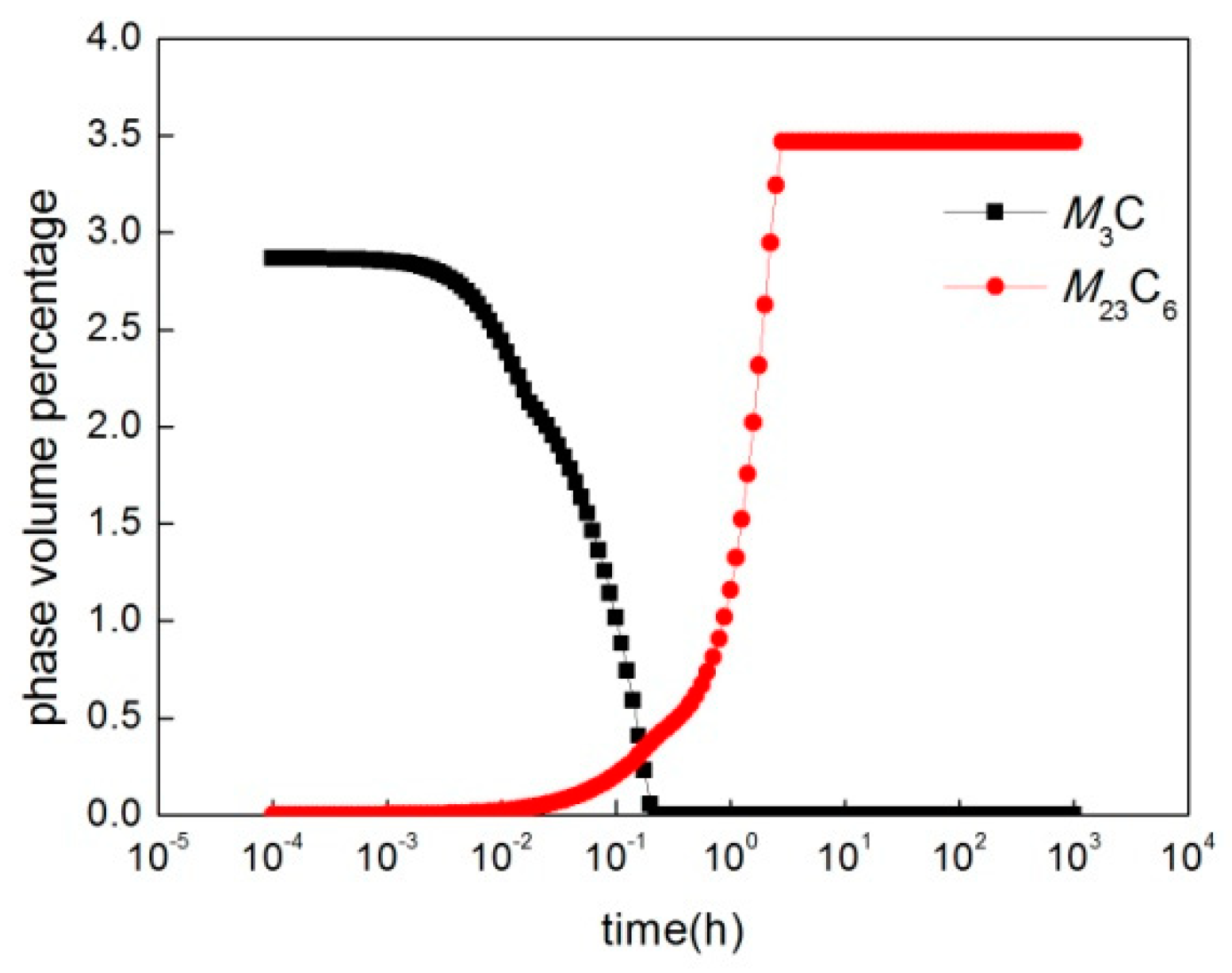
The results of the kinetic simulation are shown in Figure 7. Within about 10 s, the percentage of M3C carbides decreases at a low rate, and the percentage of M23C6 carbides remains unchanged. After about 10 s, the percentage of M3C carbides decreases faster than previously, and the percentage of M23C6 carbides begins to increase. This increase of M23C6 carbides between 10 and 1000 s is obviously coupled with the decrease of the M3C carbides. After the M3C carbides are dissolved, the percentage of M23C6 carbides keep increasing and then the system eventually approaches equilibrium between the M23C6 carbides and the matrix. As equilibrium is approached, the percentage of M23C6 carbides remains unchanged. Although the dissolution of M3C is beneficial to the creep strength of the material, the coarsening of M23C6 carbide is detrimental for creep strength.
4. Conclusions
The evolution of carbides in G18CrMo2–6 steel during 680 °C tempering was investigated experimentally combined with Jmatpro simulation.
(1) During the tempering process, there are mainly two kinds of carbides, namely M3C in the bainite matrix and M23C6 at the grain boundary.
(2) The experimental, thermodynamic and kinetic results show that when the tempering time is short, the stable M23C6 carbide precipitates and coarsens, whereas the metastable M3C carbide disappears. At the end, the M3C carbide was dissolved and the M23C6 carbide was in equilibrium with the matrix.
Author Contributions
Data curation, Z.L.; writing—original draft preparation, Z.L., P.J. and Y.L.; writing—review and editing, Z.L. and H.Q.; supervision, Z.L.
Funding
This research was funded by the National Natural Science Foundation of China (No. 51875383) and the China Scholarship Council (No. 201708140137), as well as the Doctoral Research Foundation of Taiyuan University of Science and Technology, China (20162011).
Conflicts of Interest
The authors declare no conflict of interest.
References
- Tsai, M.; Chiou, C.; Yang, J. Microstructural evolution of simulated heat-affected zone in modified 2.25Cr–1Mo steel during high temperature exposure. J. Mater. Sci. 2003, 38, 2373–2391. [Google Scholar] [CrossRef]
- Tsai, M.; Yang, J. Microstructural degeneration of simulated heat-affected zone in 2.25Cr–1Mo steel during high-temperature exposure. Mater. Sci. Eng. A 2003, 340, 15–32. [Google Scholar] [CrossRef]
- Yang, H.; Kim, S. A study on the mechanical strength change of 2.25Cr–1Mo steel by thermal aging. Mater. Sci. Eng. A 2001, 319, 316–320. [Google Scholar] [CrossRef]
- Janovec, J.; Svoboda, M.; Kroupa, A.; Výrostková, A. Thermal-induced evolution of secondary phases in Cr–Mo–V low alloy steels. J. Mater. Sci. 2006, 41, 3425–3433. [Google Scholar] [CrossRef]
- Janovec, J.; Svoboda, M.; Výrostková, A.; Kroupa, A. Time–temperature–precipitation diagrams of carbide evolution in low alloy steels. Mater. Sci. Eng. A 2005, 402, 288–293. [Google Scholar] [CrossRef]
- Tao, P.; Zhang, C.; Yang, Z.-G.; Hiroyuki, T. Evolution and Coarsening of Carbides in 2.25Cr–1Mo Steel Weld Metal During High Temperature Tempering. J. Iron Steel Res. Int. 2010, 17, 74–78. [Google Scholar] [CrossRef]
- Jiang, Z.; Wang, P.; Li, D.; Li, Y. The evolutions of microstructure and mechanical properties of 2.25Cr-1Mo-0.25V steel with different initial microstructures during tempering. Mater. Sci. Eng. A 2017, 699, 165–175. [Google Scholar] [CrossRef]
- Jiang, Z.; Wang, P.; Li, D.; Li, Y. Influence of the decomposition behavior of retained austenite during tempering on the mechanical properties of 2.25Cr-1Mo-0.25 V steel. Mater. Sci. Eng. A 2019, 742, 540–552. [Google Scholar] [CrossRef]
- Agren, J. Local equilibrium and prediction of diffusional transformations. Scand. J. Metall. 1991, 20, 86–92. [Google Scholar]
- Ågren, J. Computer simulations of diffusional reactions in complex steels. ISIJ Int. 1992, 32, 291–296. [Google Scholar] [CrossRef]
- Bjärbo, A.; Hättestrand, M. Complex carbide growth, dissolution, and coarsening in a modified 12 pct chromium steel—An experimental and theoretical study. Metall. Mater. Trans. A 2001, 32, 19–27. [Google Scholar] [CrossRef]
- Prat, O.; Garcia, J.; Rojas, D.; Carrasco, C.; Kaysser-Pyzalla, A. Investigations on coarsening of MX and M23C6 precipitates in 12% Cr creep resistant steels assisted by computational thermodynamics. Mater. Sci. Eng. A 2010, 527, 5976–5983. [Google Scholar] [CrossRef]
- Xia, Z.; Zhang, C.; Yang, Z. Control of precipitation behavior in reduced activation steels by intermediate heat treatment. Mater. Sci. Eng. A 2011, 528, 6764–6768. [Google Scholar] [CrossRef]
- Xiao, X.; Liu, G.; Hu, B.; Wang, J.; Ma, W. Coarsening behavior for M23C6 carbide in 12% Cr-reduced activation ferrite/martensite steel: experimental study combined with DICTRA simulation. J. Mater. Sci. 2013, 48, 5410–5419. [Google Scholar] [CrossRef]
- Zhu, N.; He, Y.; Liu, W.; Li, L.; Huang, S.; Vleugels, J.; van der Biest, O. Modeling of nucleation and growth of M23C6 carbide in multi-component Fe-based alloy. J. Mater. Sci. Technol. 2011, 27, 725–728. [Google Scholar] [CrossRef]
- Dahlgren, R. Prediction of Near Surface M3C after Hard Turning of SAE 52100 Steel. Master’s Thesis, Chalmers University of Technology, Gothenburg, Sweden, 2012. [Google Scholar]
- Gustafson, Å.; Hättestrand, M. Coarsening of precipitates in an advanced creep resistant 9% chromium steel—quantitative microscopy and simulations. Mater. Sci. Eng. A 2002, 333, 279–286. [Google Scholar] [CrossRef]
- Yin, Y.F.; Faulkner, R.G. Simulations of precipitation in ferritic steels. Met. Sci. J. 2003, 19, 91–98. [Google Scholar] [CrossRef]
- Li, Z.; Xiao, N.; Li, D.; Zhang, J.; Luo, Y.; Zhang, R. Effect of microstructure evolution on strength and impact toughness of G18CrMo2–6 heat-resistant steel during tempering. Mater. Sci. Eng. A 2014, 604, 103–110. [Google Scholar] [CrossRef]
- Tian, Y.L.; Kraft, R.W. Mechanisms of pearlite spheroidization. Metall. Trans. A 1987, 18, 1403–1414. [Google Scholar] [CrossRef]
Figure 1.
(a) Equilibrium phase diagram of G18CrMo2–6 steel; (b) composition of M23C6 carbide.
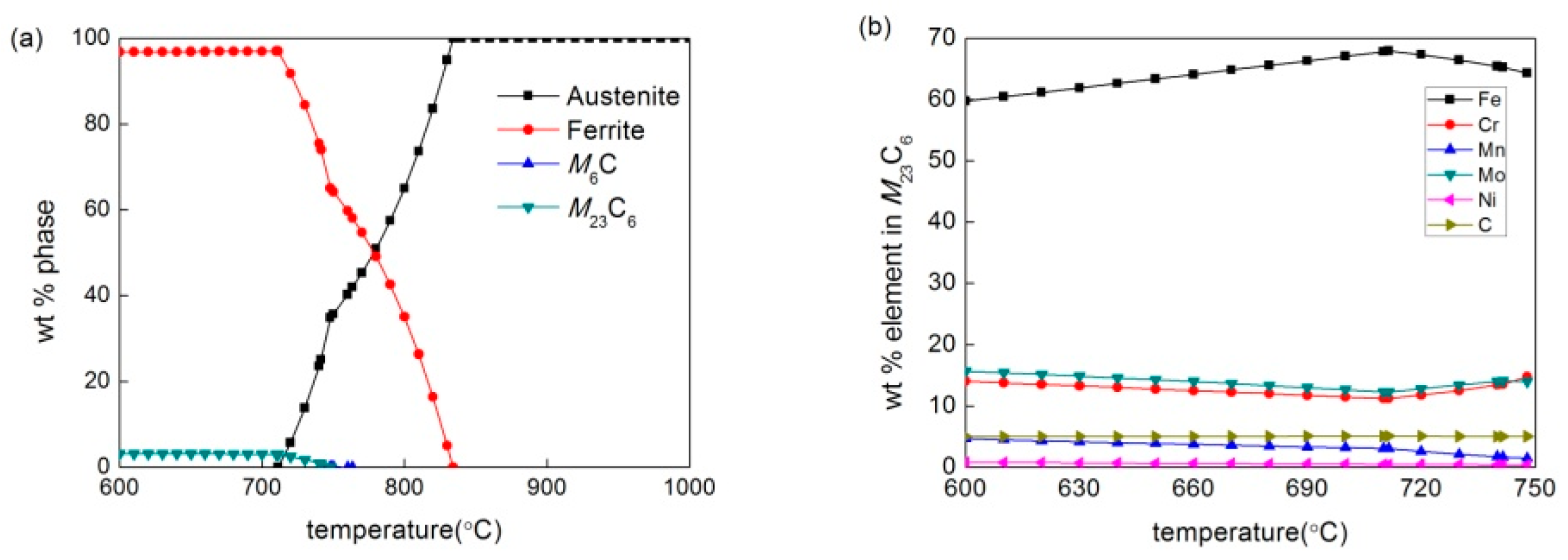
Figure 2.
Metallographic photographs of the microstructure of G18CrMo2–6 steel tempered at 680 °C for different times: (a) 0 h, (b) 100 h, (c) 500 h, (d) 1000 h.
Figure 2.
Metallographic photographs of the microstructure of G18CrMo2–6 steel tempered at 680 °C for different times: (a) 0 h, (b) 100 h, (c) 500 h, (d) 1000 h.
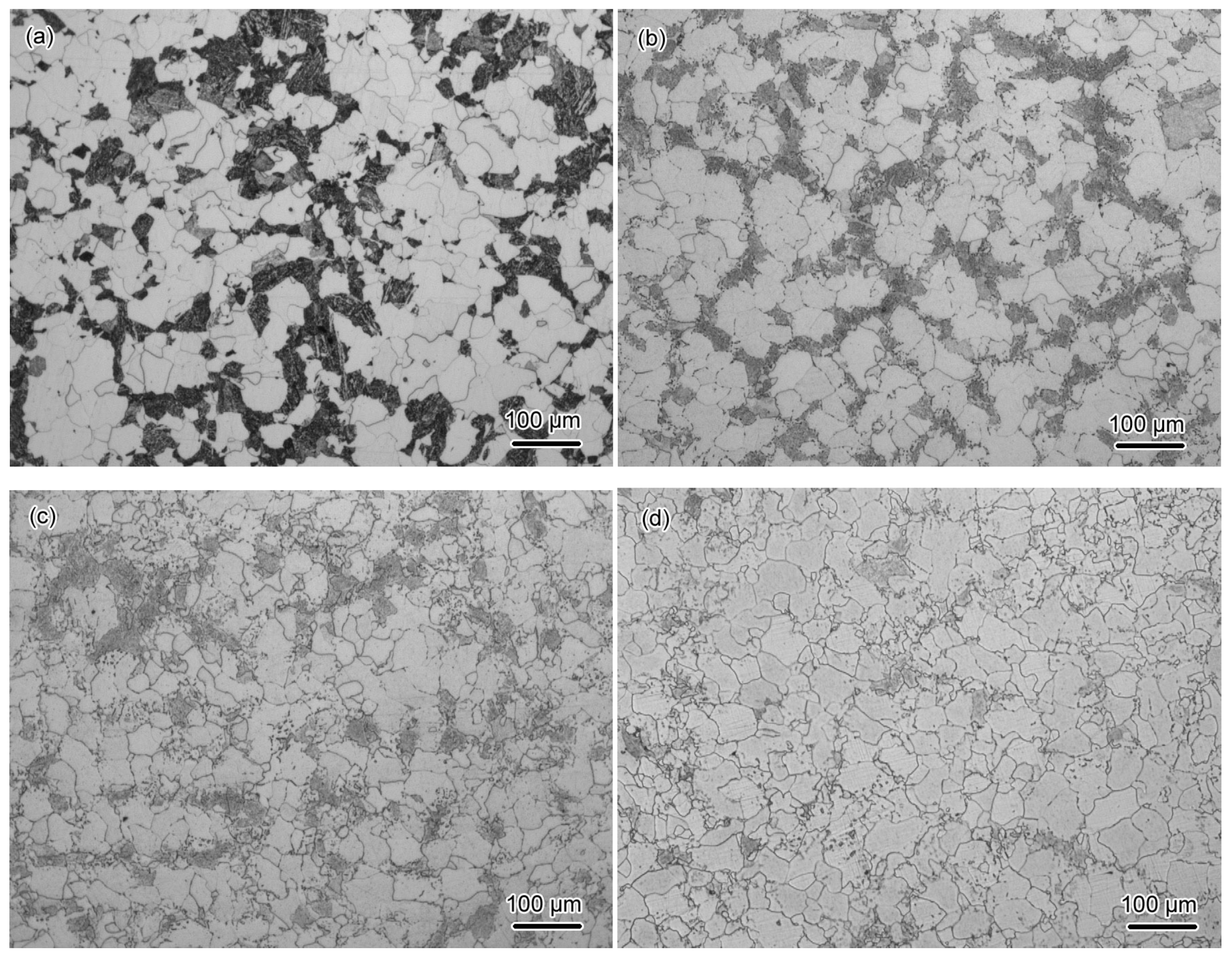
Figure 3.
Images of bainite region after tempering at 680 °C for (a) 0 h, (b) 10 h, (c) 50 h, (d) 100 h, (e) 500 h, and (f) 1000 h.
Figure 3.
Images of bainite region after tempering at 680 °C for (a) 0 h, (b) 10 h, (c) 50 h, (d) 100 h, (e) 500 h, and (f) 1000 h.
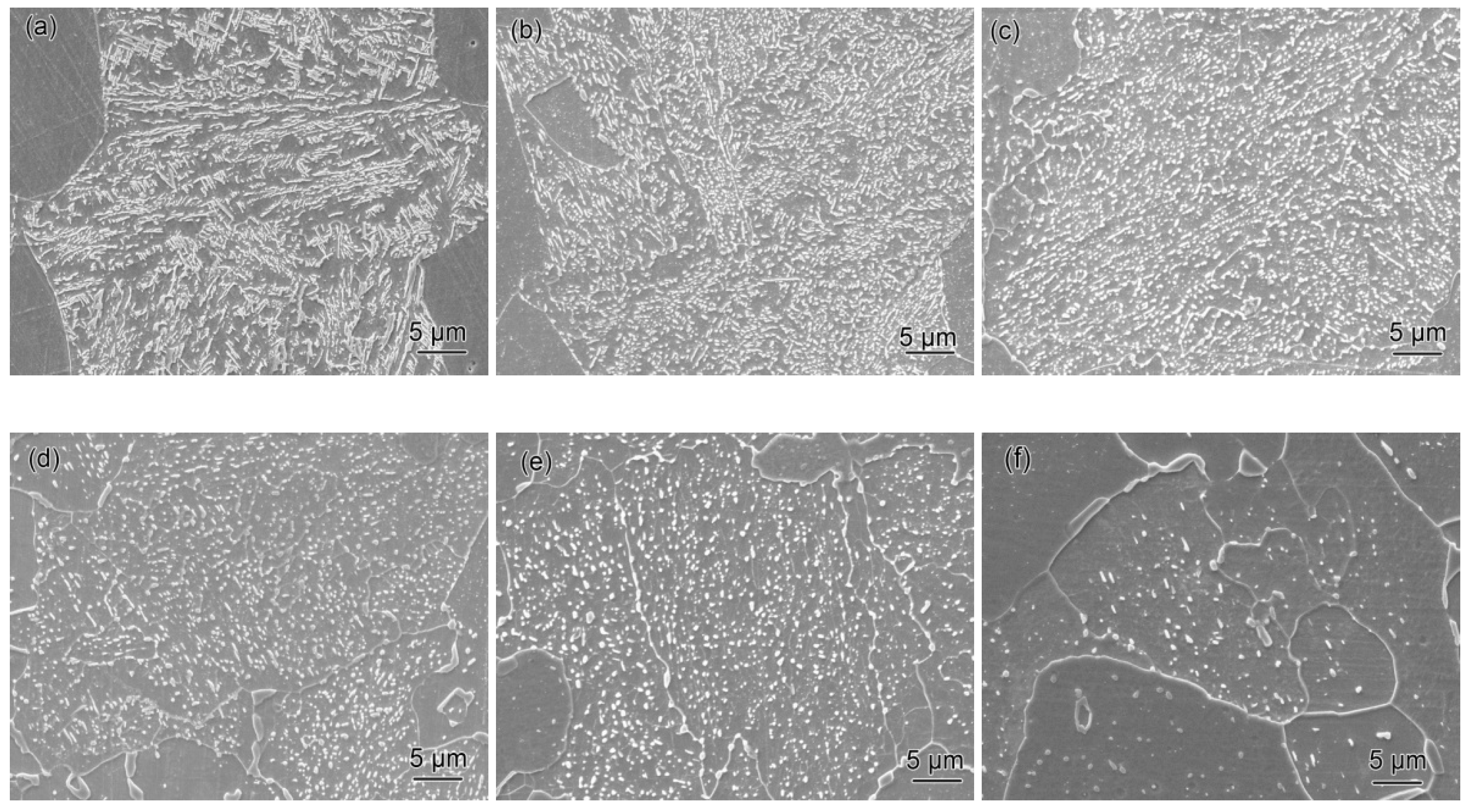
Figure 4.
Patterns of precipitate extracted from samples tempered at 680 °C for 2 h and 250 h, reproduced from [19], with copyright permission from Elsevier, 2014.
Figure 4.
Patterns of precipitate extracted from samples tempered at 680 °C for 2 h and 250 h, reproduced from [19], with copyright permission from Elsevier, 2014.
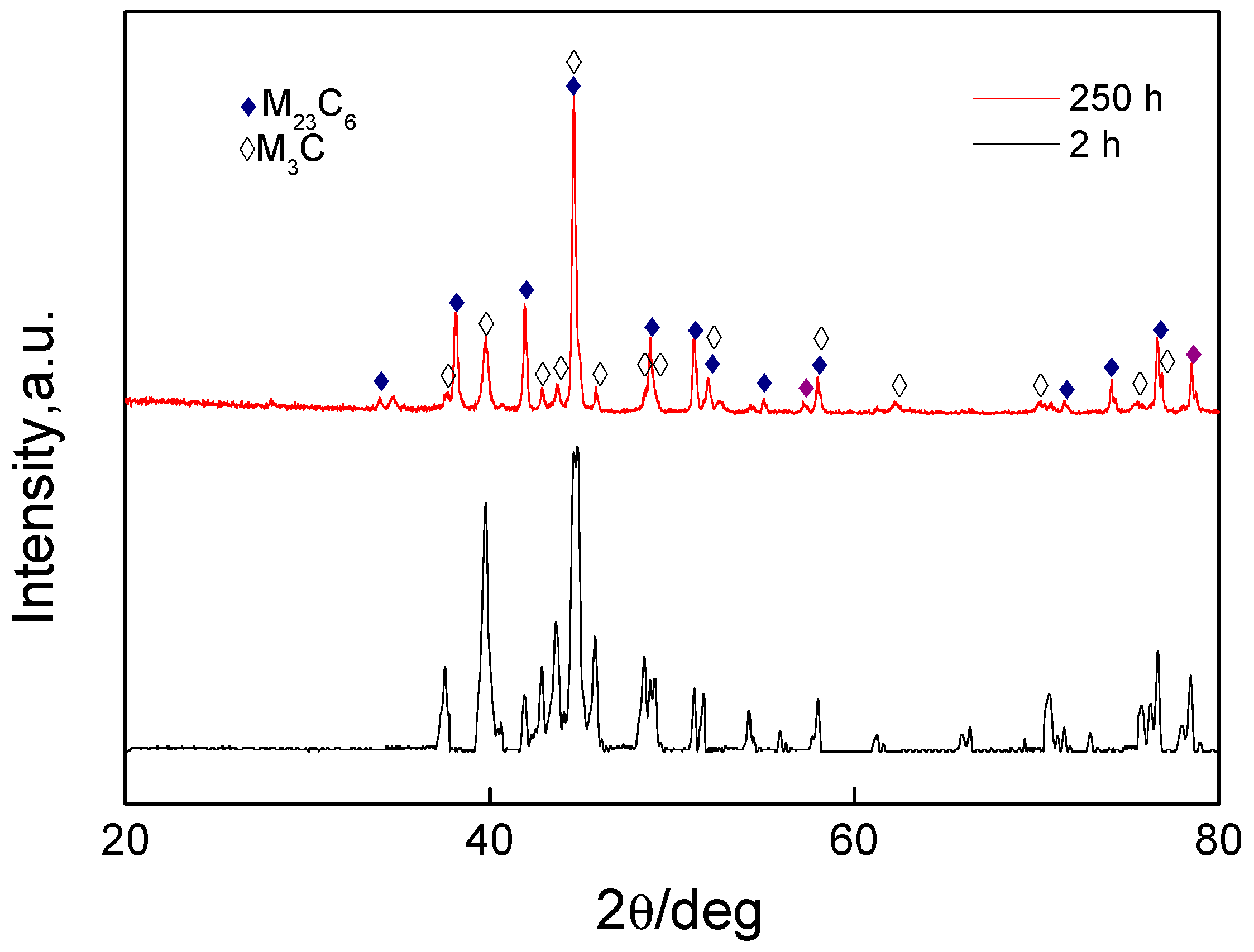
Figure 5.
Micrographs of particles within bainite: (a) 680-2, (b) 680-100, (c) SAED pattern, and (d) EDX.
Figure 5.
Micrographs of particles within bainite: (a) 680-2, (b) 680-100, (c) SAED pattern, and (d) EDX.
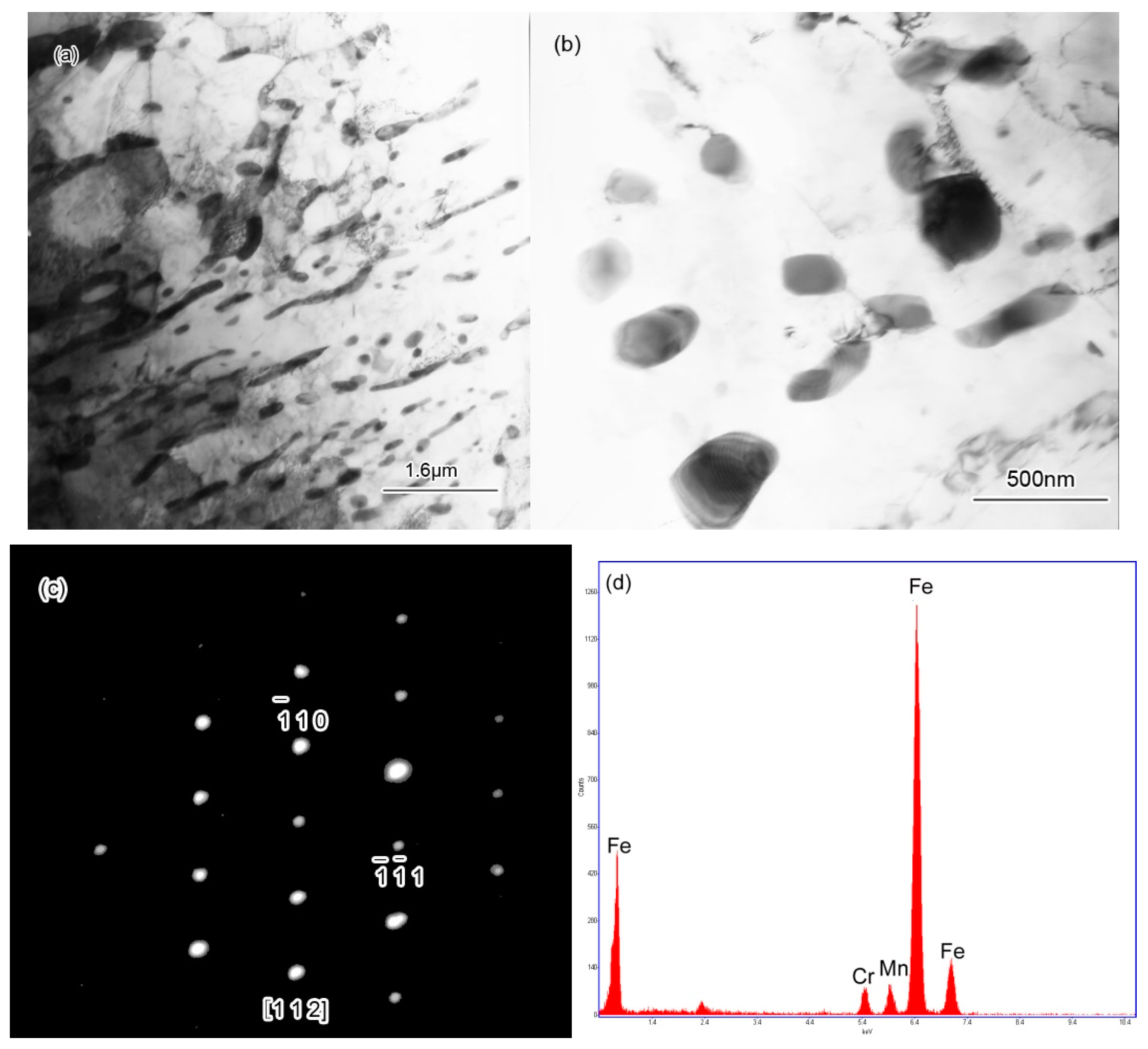
Figure 6.
(a) Micrographs of particles at the grain boundary and (b) SAED pattern.
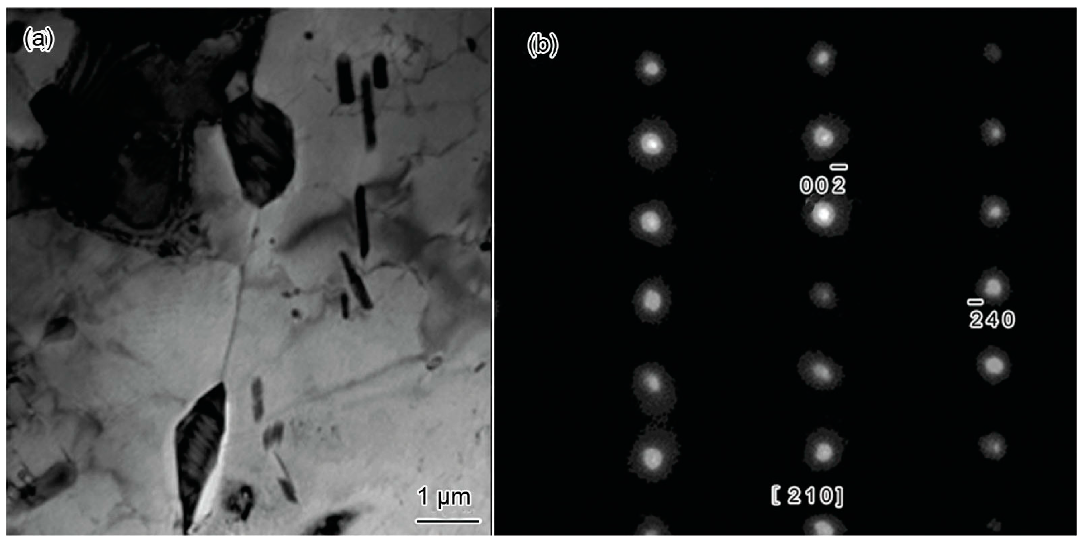
Figure 7.
Simulation of the growth of M23C6 simultaneously with the dissolution of M3C.

Table 1.
Steel compositions (wt%).
| Fe | Cr | Mn | Mo | Ni | Si | C |
|---|---|---|---|---|---|---|
| Bal. | 0.6 | 0.75 | 0.6 | 0.46 | 0.45 | 0.16 |
© 2019 by the authors. Licensee MDPI, Basel, Switzerland. This article is an open access article distributed under the terms and conditions of the Creative Commons Attribution (CC BY) license (http://creativecommons.org/licenses/by/4.0/).
Share and Cite
MDPI and ACS Style
Li, Z.; Jia, P.; Liu, Y.; Qi, H. Carbide Precipitation, Dissolution, and Coarsening in G18CrMo2–6 Steel. Metals 2019, 9, 916. https://doi.org/10.3390/met9090916
AMA Style
Li Z, Jia P, Liu Y, Qi H. Carbide Precipitation, Dissolution, and Coarsening in G18CrMo2–6 Steel. Metals. 2019; 9(9):916. https://doi.org/10.3390/met9090916
Chicago/Turabian StyleLi, Zhenjiang, Pengju Jia, Yujing Liu, and Huiping Qi. 2019. "Carbide Precipitation, Dissolution, and Coarsening in G18CrMo2–6 Steel" Metals 9, no. 9: 916. https://doi.org/10.3390/met9090916
Note that from the first issue of 2016, this journal uses article numbers instead of page numbers. See further details here.