Experimental Investigation of Novel Corrugated Steel Deck under Construction Load for Composite Slim-Flooring


1
School of Engineering, Deakin University, Waurn Ponds, VIC 3216, Australia
2
Institute for Frontier Materials, Deakin University, Waurn Ponds, VIC 3216, Australia
*
Author to whom correspondence should be addressed.
Buildings 2020, 10(11), 208; https://doi.org/10.3390/buildings10110208
Submission received: 19 October 2020
/
Revised: 14 November 2020
/
Accepted: 16 November 2020
/
Published: 18 November 2020
(This article belongs to the Section Building Energy, Physics, Environment, and Systems)
Abstract
:Trapezoidal-shaped thin-walled metallic profiled sheets are used in composite floor construction to enable rapid construction and reduce reinforcement and formwork requirements in concrete casting. However, relevant literature reported the early failure of steel sections due to the buckling and shear of existing trapezoidal and re-entrant decking profiles. There are also limitations regarding design rules for composite flooring systems. Current work aims to develop a new type of composite top-hat section for possible use in composite slim-floor construction. Sinusoidal metallic corrugated sheets that are widely used in building construction were utilized and a new bending technique was used to produce deck components, in which transverse corrugations were introduced along the main direction of the corrugated profile. This paper investigates the structural response of these new sections for several loading and support conditions using a pilot experimental scheme. The developed top-hat sections demonstrated considerable resistance to bending as well as buckling through effective stress re-distributions under considered construction stage loading for single span and continuous span conditions. Currently available design equations recommended by Australian Standards for a similar type of corrugated decks were used to predict the design strength and to compare it with those obtained experimentally. It was concluded that the expressions proposed by the code were inadequate for single span loading cases and would require modifications before being applied to the new profile.
1. Introduction
Composite construction is the usage of different materials to act in unison to provide enhanced resistance under varying loading conditions. Steel–concrete composite construction has been in practice for over a century [1,2], and has been widely adopted in major structures in Australia since 1965 [3].
Composite flooring systems are commonly used to achieve large column-free spans in buildings to enable open plan occupancy or greater flexibility in structures [4]. Cold-formed steel decking profiles have gained popularity in steel–concrete composite flooring systems as they can offer significant savings in cost and construction time by not relying on formwork during construction. Steel decks act as the formwork for concrete during the construction stage and later as tensile reinforcement once the concrete is hardened. Especially, ‘Slimflor’ and ‘Slimdek’ construction [5] introduced in the 1990s in Europe have proved to be highly efficient in their performance and have gained popularity. These slabs used integrated steel beams that are confined within the composite floor systems (Figure 1), and hence relatively shallow slabs [6] can accommodate variable floor thickness. Trapezoidal sheets or re-entrant shaped decks have been widely used for this type of composite flooring. In addition to flooring, these panels are also used in wall cladding, roofing, and bridge decks; and hence their behaviour and performance under various loading types have been extensively studied over time.
In composite flooring systems, the predominant mode of failure (Figure 2) is reported to occur due to vertical [7,8] and longitudinal shear [9,10] between the concrete and the steel deck. The shear connection at the interface of the concrete and the metallic deck is one of the key influencing factors for identifying the most efficient deck/rib configuration. Trapezoidal and re-entrant shape decks have been extensively explored for its shear and buckling properties. However, attempts to further develop innovative shapes to improve the shear and buckling resistance for composite decks are scarce in the literature. Hillman and Murray [11] developed an innovative composite flooring system using cold-formed steel decks in the form of long-span decks interlocked in an inverted hat position. Concrete was then placed on top of a very light gage, shallow steel deck which is laid transversely across the top of the inverted hat. Subsequent options to ensure sufficient interlock between the steel deck and the concrete slab resulted in more elaborate geometries including indentations and corrugations on the steel deck web and flanges. Mostly re-entrant and trapezoidal profiled sheets with or without additional features on the interface have previously been investigated for a mechanical interlock between the concrete and the profiled steel sheets [10,12,13,14,15]. The bond between both materials is formed by a mechanical clamping effect when the profiled steel sheets deform (Figure 3). However, slippage between both components will occur due to longitudinal shear stresses. Features such as embossments [16,17] or notches on steel sheet profiles [18] and an increased steel sheet thickness have been noted to positively influence the strength in composite sections. When it comes to changes in the rib geometry, the effect of high ribbed decks on the strength and shear connection has also been studied. Thondel and Studnicka’s study widened the limits for rib heights provided in the European codes [19]. The introduction of different shapes of stiffeners also improved the profile geometry and corresponding strength in buckling, but most studies directed to the modification of deck profiles primarily focused on variations of trapezoidal or re-entrant deck types.
The design of composite flooring systems is usually carried out in two phases, i.e., (i) the construction phase; when the steel sheeting by itself must be capable of carrying the weight of wet concrete, workmen, tools, and other live loads; and (ii) the service phase; when the hardened concrete develops composite action with the steel deck to carry both the design dead and live loads. However, previous work on steel decks was mostly limited to composite stage testing; that is with the presence of concrete. Very few reports [20,21,22] assessed the performance of the separate steel decks under construction loading. This information is essential to efficiently design steel decks for composite floor systems [8] and to address issues of buckling and shear failure. The geometry and flexibility of steel sheet under construction loads significantly affect the overall behaviour of slabs as reported in parametric studies on various types of corrugated decks conducted by Degtyarev [23]. The results showed that properties such as the geometry of the deck and the loading condition greatly influence the strength, behaviour and effective transverse width distribution of the decks [23]. Regarding prediction of the behaviour of thin-walled decks in the construction stage, some other studies focused predominantly on the resistance of decks during construction when subjected to a combination of the moment and contact pressure from support reactions [24,25,26].
This paper introduces a new profile developed to improve the performance of thin-walled decks and to address common issues of shear failure and buckling [16,17,27] seen in commonly available deck types. The research presents an innovative multiple hat section produced from Lysaght’s CUSTOM ORB profile, as detailed in the next section. The proposed sections are manufactured using a new metal forming technology developed by an Australian manufacturer [28] which introduces transverse corrugations into the main direction of the corrugated profile.
Conventional trapezoidal and re-entrant decks have already been covered by existing standards for their strength, manufacturing and use in various engineering applications. Nevertheless, the strength of these decks is affected by buckling and limited shear capacity due to various reasons such as inefficient rib geometry, and the yield and tensile strengths of profiled decks. Hence, there is a need for the provision of additional features such as embossments and stiffeners. Thus, the current research is aimed to assess the structural performance of a proposed steel deck geometry under the construction load in light of the concerns above. The test outcomes under construction load will help understand the contribution of the bare steel sections in composite action when concrete is incorporated. The applicability of the novel profile is evaluated through the testing of a set of multiple top-hat section decks and a single top-hat section under different construction loading conditions specified in AS/NZ 2327-2017 [29]. The new decks may be used in many structural applications including slim-floor systems where the depth of the floor deck will incorporate the supporting beam. This composite slim-floor system could prove efficient in structural performance as well as in cost-effectiveness.
Design codes for composite floor systems are outlined in Europe EN 1994-1-1 [30] and in Australia AS/NZ 2327-2017 [29]. In the current study, the deck with a multiple hat section was tested for its deck type properties in a single span, continuous span and end span settings as per the testing guidelines recommended in AS/NZ 2327-2017 [29]. It is worth noting that most guidelines have been developed for trapezoidal-shaped decks, and hence relevant modifications were made to suit the testing of the proposed corrugated shape used in the current study. Obtained test results were compared with those determined following general design rules for steel structures presented in AS 4100-1998 [31] and those for cold-formed steel sections in AS/NZ 4600-2018 [32]. It was concluded that the design recommendations proposed by the code are inadequate for certain loading cases and require revisions before applying to the new profile.
2. Development of New Corrugated Deck Geometry
2.1. Proposed Top-Hat Composite Deck
An innovative metal bending technology has recently been developed in Australia [28], which produces smooth bent corners (Figure 4) in a commercially available Lysaght CUSTOM ORB corrugated sheet at a variety of angles. This technology is known as FormFlow, which has been used in the current work to produce a novel steel deck geometry for possible use in a slim-floor composite system. This incorporates novel top-hat sections produced from a commercially available Colorbond sheet. These sinusoidal corrugated Colorbond sheets were bent at 90° to form the hat sections. Two groups of samples were manufactured such as a single top-hat section (Figure 5a) and multiple rows of hat sections (Figure 5b). These sections were produced by introducing bends in transverse direction on sinusoidal corrugated sheets. The single top-hat section was tested to understand the behaviour of an isolated corrugated top-hat section under flexural loading. A detailed cross-section of the developed hat section is shown in (Figure 5c). A multiple hat section (Figure 5d) was also investigated to examine its ability to act as a deck. The role of the single top-hat is to act as ribs within the developed deck to form efficient top-hat composite decks to be used in slim-floor composite construction (Figure 5e). The traditional shallow decking profiles are between 45 and 60 mm high with a rib spacing of 150–333 mm [33]. The current tool available for bending the corrugated sheet is restricted to a minimum channel width and height of 60 mm. Therefore, the developed deck dimensions include three hat sections forming a total width of 480 mm, with 1200 mm in length and 60 mm in height.
The advantage of the unique technology is that it avoids the need for capping, flashing or complex corner designs. In addition to this, the technology enables the development of new, stronger and an ultra-functional corrugated strip that can be adopted for different applications in construction. Decks are often susceptible to local buckling due to typical large width-to-thickness ratios, which require the use of complex stiffeners. Previous studies on the optimisation of deck geometries have mainly been limited to varying the dimensions of standard cross-sections such as trapezoidal or re-entrant decks [17,34]. The top-hat composite deck is advantageous when compared to conventional trapezoidal or re-entrant decks. This is because corrugated sheets are already strong along the axis of corrugation and the geometry of the innovative profile provides higher resistance to buckling by introducing bends that are transverse to the corrugation direction. These top-hats may provide additional strength in the perpendicular direction in addition to the main corrugation direction. Likewise, normal trapezoidal decks have a longitudinal stiffener in the middle of the rib to improve the load-carrying capacity as well as the buckling resistance of the decks. However, this makes it impossible to place shear studs centrally, and thus giving rise to favourable and unfavourable sides in secondary beams [35], which is reported to be a major construction issue. In comparison to this, the in-depth sinusoidal cross-section of the top-hat composite deck as well as a vastly different shear interface geometry could offer additional axial and bending stiffness. The unique and irregular geometry of the top flange may act stronger in buckling and help prevent having to use stiffeners. Additional shear strength capacity in the composite stage could also be achieved by the irregular surface of the profile. The proposed profile can reduce shear failure because the possible slip between two materials can be greatly suppressed by the transverse corrugations. In addition, the new profile can transmit shear forces over a wider area with the absence of a sharp geometry usually seen in embossments which would easily break concrete. Therefore, the tearing failure produced on the sheet causing the separation of the steel profile and concrete may be avoided. Thus, the current research investigates the strength capacity of the new top-hat composite deck developed using the new forming technology for possible improved application in composite slim-floor construction.
2.2. Significance of Material Used for Top-Hat Composite Deck
Corrugated metallic sheets with sinusoidal waves produced using a cold-forming process is a fairly old product that has been used in roofing since it was first patented in 1829. Given the structural strength it provides along the axis of corrugations, corrugated iron has been extensively used in various applications such as sheds, roofing or water tanks. Corrugated sheets are typically galvanised with zinc coating for corrosion resistance. However, in 1888 [36], John Lysaght Ltd. (Melbourne, Australia) introduced a galvanising machine to apply an even coating of homogenous colour on the surfaces of corrugated iron sheets. This is widely known as “Colorbond” in the construction industry and has been extensively used in roof covering. The galvanised side of the steel sheet is essentially used for the composite phase. Adhesion and frictional interlock is established between the steel and concrete. However, in the new deck, the main deterrent to slip and separation, as normally seen in other profiled sheets, is the presence of the corrugations in both directions. Although modern manufacturing techniques can produce varying lengths of corrugated sheets, their use has been limited to roofing or cladding for architectural purposes. The enhanced stiffness due to corrugation remains neglected by not employing theses sheets as load-carrying features. The qualities and economy of corrugated metal come from the efficiency of its strength to weight ratio, where maximum strength is achieved from the minimum use of material. Its load-carrying capacity can be utilised efficiently if designed for specific needs. Furthermore, any product introduced in the mainstream construction market should be cost competitive. Colorbond is an easily available commercial product that has been extensively used for various small-scale construction purposes and hence is a proven cost-effective material. In addition to the material cost savings, significant cost-reduction is obtained from FormFlow technology due to specific tooling tailored for all corrugated shapes, reduced manufacturing processes and site activity.
The typical thickness of metallic profiles used in composite decks vary between 0.7 and 1.1 mm. Although Colorbond steel satisfies the thickness properties and other features necessary for composite decking such as material and finish, the geometrical properties such as the depth of the profile makes it unsuitable for direct application as steel decking in composite slab construction. The simple rib profile cannot incorporate the required depth for decks and can easily lead to shear failure and slip. Therefore, developing a deck profile with the Colorbond corrugated sheets for possible use in composite construction could prove beneficial. The development of FormFlow technology opened up the opportunity to produce innovative structural shapes for civil engineering applications.
3. Overview of Test Program
To develop a suitable design for the new sections and to investigate the contribution of these steel sections in a composite stage with concrete, it is important to test the bare steel sections for initial strength assessment under construction stage loading. Material properties were obtained from tensile coupon tests. A single top-hat section was tested for its behaviour under four-point bending arrangement, whilst multiple hat sections were tested under various deck arrangements to understand the structural behaviour during construction. The conducted tests included three groups of experiments that replicate all loading conditions during construction, i.e., a single-span test, continuous span test, and an end span test based on the construction phase guidelines recommended by AS 2327:2017 [29]. Single span tests were conducted to assess the flexural capacity and general behaviour of these decks. Decks with continuous span were also tested for negative moment exposure and continuity conditions. Finally, end support tests were conducted to replicate the outer supports of the decks and to evaluate the resistance of the deck to concentrated shear loads in the absence of a bending moment. Three different test arrangements provided comprehensive information on the performance of the proposed corrugated multiple hat sections.
3.1. Material Properties
The base metal has an average thickness of 0.75 mm steel with a zinc coating of 0.04 mm on one side and a food-grade polymer film on the other side giving an overall thickness of 0.9 mm. Tensile tests were performed on five samples cut from a flat sheet in the rolling direction and before the corrugations were roll formed. Tests were performed as per AS 1391-2017 [37] and the applied load was measured using a load cell of 50 kN attached to an Instron testing machine. Figure 6a shows the dimensions of the coupons used and Table 1 summarizes the mechanical properties of the material obtained from the stress–strain curves (Figure 6b) obtained from the tests.
3.2. Tests on Single Hat Sections (Experiment Group (a))
To investigate the behaviour of the manufactured isolated hat sections and their contribution in decks, standard flexural tests as per AS 2327-2017 [29] were performed on two top-hat section beam specimens (B1 and B2) using a universal testing machine of 500 kN capacity. The four-point bending test configuration with a span of 1000 mm is shown in Figure 7a,b, was used to determine the load (F) vs. deflection (δ) relationship of the top-hat beams. To capture the full load–deflection curve, tests were commenced with a load control and changed to the deflection control after stable loading was attained. A constant deflection rate of 1.5 mm/min was applied and deflections were carefully recorded. A laser transducer was used to record the deflection of the hat as a function of the load which was applied by a hydraulic actuator as shown in Figure 7a. The first beam specimens was tested using a corrugated timber block to uniformly transfer the applied loads on to the corrugated sheet. However, the use of corrugated timber block in B1 (Figure 7d) resulted in a loss of contact in some parts and movement of the timber block, as shown in Figure 7e, also affecting the test response. Hence, flat timber blocks were used for testing B2 as shown in Figure 7c. No slip or movement was noticed when it switched to flat timber blocks as the blocks maintained constant contact at the tops of the hat-section through the entire loading of the samples. The timber blocks were 85 mm wide to efficiently be held in place between the rollers and two top corrugations of the hat-section samples. Load–deflection relationships were recorded along with observed failure modes. The ultimate moment and shear capacity of the sections were also calculated from the recorded experimental results.
3.3. Tests on Multiple Hat Sections
3.3.1. Test Set-Up for Single-Span Decks (Experiment Group (b))
To examine the flexural capacity of the multiple hat section deck, four simply supported single span specimens of 1000 mm effective span and 480 mm width were tested. The cross-sectional properties are the same as detailed in Figure 8a. The test arrangement was set according to AS 2327-2017 [29], Appendix F Standard Tests—Tests on Profiled Steel Sheeting. Decks with a total length of 1200 mm and a span length of 1000 mm were subjected to two transverse loads that were applied at one-third of the spans. Loads were uniformly distributed along the width using flat timber blocks as shown in Figure 8b. Timber blocks were also used at support sections following the design code recommendations to prevent the opening of webs due to reaction forces at supports. The mid-span vertical deflection of the decks was measured using laser transducers. Load–deflection relationships were recorded along with observed failure modes. The ultimate moment and shear capacity of the sections were also calculated from the recorded experimental results.
3.3.2. Test Set-Up for Continuous Span Multiple Hat Sections (Experiment Group (c))
During the construction stage, decks are subject to a combination of moment and concentrated forces at internal supports. To analyse the resistance in continuous span condition, additional bending tests were conducted on two continuous decks with a total length of 2000 mm, spanning over three supports with two 1000 mm spans following AS 2327-2017 [29] (see Figure 9a,b). This set-up is recommended to evaluate the resistance of the multiple hat section when subjected to negative moments at the internal support. To simulate a uniform load distribution, the load was applied through four transverse line loads using two 400 mm-long steel rectangular hollow sections (RHS), supported on roller supports that eventually transferred the loads on to the deck through flat timber blocks. Hinge bottom supports were applied using clamps so that the deck was allowed to rotate only when roller supports were used at the ends. The vertical deflection was measured with laser transducers at two mid-span sections. Load–deflection relationships were recorded along with observed failure modes. The ultimate moment and shear capacity of the sections were also calculated from the recorded experimental results.
3.3.3. Test Set-Up for End Support Region of the Multiple Hat Section (Pure Shear Capacity) (Experiment Group (d))
Lastly, two end support deck tests (ESD1 and ESD2) were conducted to replicate the outer supports of the decks and to evaluate the resistance of the deck to concentrated shear loads in the absence of a bending moment. The end support test explores the behaviour of the deck under local transverse forces and helps understand the resistance of edge supports. Tests were also carried out following recommendations given in AS/NZ 2327-2017 [29], Appendix F specifications. The distance from the internal edge of the end support to the end of the deck ‘u’ was kept at 50 mm as recommended by the design code. Figure 10 presents the general view of the end support test configuration decks. The decks were tested under simply supported conditions and the load was applied at a bearing length of 300 mm, as suggested in the design code. Vertical deflections at the loading sections were carefully measured.
4. Test Results and Discussion
4.1. Results of Single Hat Sections (Experiment Group (a))
In corrugated top-hat beam specimens (B1 and B2), no local buckling of the flanges or the bottom plate was observed; tests were terminated due to excessive deflection (Figure 11). In B1, an early load drop was observed due to the loss in contact with the corrugated timber block support. When flat timber blocks were used for testing B2, a steady increase in load was observed with large deflections but without significant load reduction. The applied load was maintained as the deflection of the beam increased to nearly 90 mm in B2 and the test was stopped. Figure 12 shows the obtained load–deflection curves for B1 and B2 with an average maximum load of 0.87 kN for the two tested top-hat beams. These results show the contribution of each of these hat sections in a deck and can be optimized to receive maximum performance. Test results are summarised for ultimate load and deflection with the corresponding shear and moment capacities in Table 2.
4.2. Results of Multiple Hat Sections
4.2.1. Results of Single-Span Decks (Experiment Group (b))
Four single-span decks (SSD) tested as part of the current research showed the limited local failure of flanges around the loading regions as seen in Figure 13b. Geometric deformations were visible as the sheets splayed outwards and the outer flanges came undone due to excessive deformation behaviour as shown in Figure 13a. The test was stopped when the deflection exceeded 80 mm and the applied load reached a plateau; the load vs. mid-span deflection relationships for all four single-span decks are shown in Figure 14. An average ultimate load of 2.11 kN was recorded for the four tested decks. The corrugations on the outer flanges were noticeably spread wide at the maximum moment for all four samples. AS 2327-2017 details minimum construction loads occurring in three stages for the decks of particular spans without propping. The mean construction load is determined as a sum of the mean dead loads and live loads on the decks over three stages. Dead loads include the weight of steel sheeting, the reinforcements placed as well as fresh concrete, and a uniformly distributed live load of 1kN/m2 is also considered. Therefore, the total construction load may be taken as 2.05 kN for the considered deck configurations. Mean capacities obtained from the test results show sufficient load capacity in the construction stage and thereby prove the adequacy of the proposed deck types to be used as profiled decks in composite construction. Seeing that no major material failure has occurred, the decks can be significantly strengthened when confined within concrete in the composite stage. The minimal buckling failure observed during tests prove that these decks offer better resistance to possible local failure than available trapezoidal and re-entrant decks. The details of the test results for the ultimate loads and deflections with the corresponding shear and moment capacities are summarised in Table 2.
4.2.2. Results of Continuous Span Multiple Hat Sections (Experiment Group (c))
The load–displacement curves for two continuous span decks (CSD1 and CSD2) are shown in Figure 15a. The initial local failure of the decks occurred at the middle support section for both CSDs due to the local failure of the compression region of the cross-section as shown in Figure 16a. Failure due to crushing was also observed at mid-spans of the load points as shown in Figure 16b. For CSD1, a reduction in stiffness was observed when the applied load reached approximately 6.9 kN, resulting in a moment of 0.59 kNm, and triggered local failure at the internal support. After this, the deck continued to resist additional loading and ultimately the test was stopped after exceeding a load of 7 kN and an ultimate moment of 0.64 kNm due to excessive deflection. However, in the CSD2, the collapse of the mid-support occurred at a maximum of 7.2 kN and a slightly higher moment of 0.62 kNm was attained. There is a strength reserve due to the moment redistribution when the internal support buckles. This is evident from the internal support buckling at nearly 90% of the ultimate load. Strain distribution measurements near the mid-support on the bottom surfaces of the section is also shown to verify this assumption. Although the stress–strain relationship is non-uniform for the two samples, variations in strain were observed to be close to the mid-support failure in both samples as shown in Figure 15b. Test results for continuous decks are also detailed in Table 2.
4.2.3. Results of End Support Region of the Multiple Hat Section (Pure Shear Capacity) (Experiment Group (d))
The collapsed deck of the end span tests shows significant failure under the interior loading plate but not the anticipated support section failure under concentrated shear force as can be seen in Figure 17. The failure loads Fu and corresponding displacements at loading section du are shown in Table 2. Figure 18 presents the load–deflection curves corresponding to the loading section for the end support tests. Figure 17 shows the distance from the internal edge of the end support to the end of the deck, shown as u = 50 mm, did not influence the failure mode. The sections failed prematurely under the loading region of the specimens rather than at the end support, and the collapsed deck showed only minor deformations at the ends. Hence, the observed failure was a combination of bending with some interaction with support reaction, which was not the expected outcome from the test. Nevertheless, due to the absence of significant web crippling, the results demonstrate that the proposed new deck types will not undergo early end support failure, and deck action will not be limited by this behaviour.

Table 2.
Summary of test results.
| Sample No. | Ultimate Load Fu (kN) | Ultimate Moment Capacity Mu (kNm) | Ultimate Shear Capacity Vu (kN) | Ultimate Deflection du (mm) |
|---|---|---|---|---|
| Single Top-Hat Section—Flexure Test (Experiment Group (a)) | ||||
| B1 | 0.88 | 0.15 | 0.44 | 46.90 |
| B2 | 0.86 | 0.14 | 0.43 | 69.27 |
| Average | 0.87 | 0.145 | 0.435 | 58.08 |
| Multiple Top-Hat Composite Deck—Single-Span Test (Experiment Group (b)) | ||||
| SSD1 | 2.05 | 0.34 | 1.03 | 83.78 |
| SSD2 | 2.17 | 0.36 | 1.09 | 76.40 |
| SSD3 | 2.08 | 0.34 | 1.04 | 73.95 |
| SSD4 | 2.13 | 0.35 | 1.07 | 71.10 |
| Average | 2.11 | 0.35 | 1.06 | 76.31 |
| Multiple Top-Hat Composite Deck—Continuous Span Test (Experiment Group (c)) | ||||
| CSD1 | 7.51 | 0.64 | 2.54 | 61.35 |
| CSD2 | 7.45 | 0.63 | 2.52 | 63.78 |
| Average | 7.48 | 0.635 | 2.53 | 62.56 |
| Multiple Top-Hat Composite Deck—End-Span Test (Experiment Group (d)) | ||||
| ESD1 | 8.61 | 0.39 | 7.75 | 15.31 |
| ESD2 | 8.58 | 0.38 | 7.72 | 15.29 |
| Average | 8.59 | 0.385 | 7.74 | 15.3 |
Figure 17.
Local failure near the support.

Figure 18.
Load vs. displacement for end support deck tests.

It is important to note that this test arrangement was initially designed for plain trapezoidal decks and its applicability to cross-sections similar to the ones used in the current study would require modification; some amendments to the test set-up are suggested herein for future reference. It is evident that the local transverse resistance of webs closer to end support is higher. As seen in various end-one-flange loading tests on decks in the literature, it is necessary to keep the span length very short and the bearing plate under the load much wider than the support bearing plates. Span lengths used in some successful studies [38,39,40] of end span loading of decks can be adopted in such cases. In these tests, the distance from the support on each side to the loading plate should not be less than 1.5 h, where h is the height of the deck. Previous studies also reported that the influence of ‘u’ is insignificant on the ultimate resistance of decks and the length of bearing support could play a significant role in such behaviour. Further strengthening of the midspan region of the test specimens using pieces of the same deck type could prevent unwanted flexural failure and should help yielding results relevant to shear failure at end support.
In conclusion, the test set-up provided in AS 2327:2017 [29] is unsuitable and inadequate for any type of deck other than trapezoidal decks and would require modifications as suggested for the deck in consideration for capturing an appropriate structural response.
5. Comparison of Deck Strength with Design Strengths Predicted by the Australian Code
5.1. Assessment of Hat Sections (Experiment Group (a)) and Single-Span Multiple Hat Sections (Experiment Group (b))
Ultimate resistances for the considered decks were calculated according to AS 4600:2018 [32] and AS 4100:1998 [31]. This is to assess the relevance of the formulas available in the codes for the new deck types considered in the current research. Moment resistances calculated for top-hat sections are compared in Table 3 with those achieved in tests (experiment group (a)). The nominal section moment resistance (Ms) of hat sections were determined as follows:
where Ze is the effective section modulus calculated with the extreme compression or tension fibre at fy. The nominal member moment resistance Mb is then calculated from Ms as per the provisions in the code.
Similarly, AS 4600:2018 does not particularly provide additional guidelines for cold-formed sections such as decking profiles. The equation used to assess hat section resistance was also used for the single-span deck. Bending moments calculated for all cases are compared in Table 4 for SSD types with those attained in tests (Experiment group (b)).
According to these results, AS 4600:2018 [32] overestimates the predictions for the bending moment resistance. There is a need to improve the equations to include the properties of the new proposed top-hat section. Resistances predicted through the standard equations for the sections are overestimated since the section properties of the complex geometry need to be investigated further. There is a variation in the cross-section due to corrugations and accounting for this as a reduction factor will yield a result close to the experimental result. Future work requires the standard formula to be revised for the prediction of moment resistance of the deck by further investigating the section properties to incorporate the effects of the varying and non-uniform cross-section.
5.2. Assessment of Continuous Span Decks (Experiment Group (c))
Continuous deck tests were conducted to determine the resistance for the combined bending moment and support reaction over two or more spans for a given support width. Consequently, the failure of middle support occurred due to the bending moment–support reaction interaction, which reduced the resistance of the internal support section.
In this section, experimental reactions Rs at collapse load Fs of internal support are compared to the design resistances Rc calculated from the expressions provided in AS 4600-2018. The reactions at the middle support Rs was determined from the test results to compare against those predicted using code equations, which provide a design concentrated load or reaction Rc in the presence of the bending moment. Hence, for comparison, the resistance of the section is recognized as the reaction at the middle support from experimental and theoretical results. Therefore, the analysis of these decks is expressed in terms of the reaction force at failure around the internal support. Since the strength of continuous decks is directed by the bending moment and bearing force interaction at the internal support, AS 4600-2018 [32] presents the following expression for combined bending and bearing for unstiffened webs:
where:
- R* = design concentrated load or reaction in the presence of the bending moment;
- Rb = nominal resistance for concentrated load or reaction in the absence of bending moment;
- ɸb = capacity reduction factor for bending;
- ɸw = capacity reduction factor for bearing;
- M* = design bending moment at, or immediately adjacent to, the point of application of the design concentrated load or reaction (R*);
- Ms = nominal section moment resistance about the centroid;
Further Rb, which is bearing in the absence of holes or openings is given as
where
- C = coefficient;
- tw = thickness of the web;
- = angle between the plane of the web and the plane of the bearing surface and shall be within the limits of 90° ≥ ≥ 45°;
- Cr = coefficient of inside bent radius;
- ri = inside bent radius;
- Cl = coefficient of bearing length;
- lb = actual bearing length;
- Cw = coefficient of web slenderness;
- dl = depth of the flat portion of the web measured along the plane of the web;
In this experiment, the middle support collapsed at a load Fs. The corresponding reactions obtained at middle support (Rs) were compared to the design resistances calculated using Equation (3) as given by the Australian Code, and obtained results are presented in Table 5. Values for the required design parameters in Equation (3) were obtained from AS 4600-2018 [32].
Experimentally obtained reaction forces at the internal support (Rs) were compared with the relevant resistances (Rc) predicted using Equation (3), which produced 27% conservative results. The observed conservatism may be attributed to the geometry of the decks as the present equation was proposed for flat hat sections or decks. In addition, the bending moment redistribution at the internal support may have contributed to this observed conservatism since the middle supports failed at load levels of almost 90% of the final capacities.
5.3. Assessment of End Span Decks (Experiment Group (d))
The failure of the tested end-supported multiple hat sections showed failure due to the interaction of moment and local force. Hence, Equation (2), which has already been introduced for continuous span tests, was used to investigate the design resistance of the deck and this equation incorporates the combined effects of bending and bearing for unstiffened webs. Ultimate experimental reactions Rs are reported in Table 6 with the calculated design resistance Rend. The nominal web crippling resistance Fend of cold-formed sections at end supports is given by previously presented Equation (3). However, different classification based on the test were used for the coefficients. That is, the parameters used in Equation (3) conform to the end support conditions following information from AS 4600-2018 [32]. Other parameters such as bearing length was also changed according to the test set-up. Comparisons between the measured ultimate web crippling load Fu and the predicted nominal web crippling load Fend as per Equation (3) are also reported in Table 6.
It is obvious from the results that the ultimate loads obtained from the experimental tests are higher than those predicted using the Australian code. It is worth noting that the end support results were also analysed for web crippling load using Equation (2) but with different expressions used for the internal support instead of the end support; this was presented as Fint and the corresponding resistance Rint was obtained using Equation (3). It was observed that this technique produced results closer to the experimental values but are still conservative. This can be attributed to the observation that the failure behaviour of the conducted end support tests was not the typical support section failure; and suggested modifications to the test set-up, as outlined in Section 4.2.3, would help achieve targeted results. Nevertheless, due to the absence of significant web crippling, it may safely be assumed that that the new deck types will not undergo early end support failure and deck composite action will not be limited by this behaviour.
6. Conclusions
Current research presents a complete experimental study on a new form of corrugated steel multiple hat decks as well as a top-hat section to determine their resistance under construction stage loading for typical support conditions. Three different test configurations were adopted in the experimental plan to portray the behaviour of the decks under different loading conditions; simply supported deck tests, continuous deck tests over two spans and end support tests. Following are the major observations that can be summarised from test results:
- (i)
- The proposed profiles efficiently resist construction stage loadings. Minimal buckling failure also indicates that the deck can be sufficiently strengthened when confined within concrete in the composite stage.
- (ii)
- The failure pattern of the single-span decks are comparatively different to regular decks due to limited buckling, but large deflections. Existing code equations for trapezoidal decks failed to accurately predict the test resistances of the proposed deck. Code predictions were overestimated by around 37% for the individual top-hat sections and by 31% for the top-hat composite decks.
- (iii)
- The comparative results showed that expressions in the codes may be generally applicable to the new sections, however, appropriate modifications should be introduced to obtain accurate prediction values. Resistances predicted through the standard equations for the sections are overestimated since the section properties of the complex geometry need to be investigated further. There is around 29% variation across the cross-section of the profile due to corrugations and accounting for this variation as a reduction factor will yield a result close to the experimental result.
- (iv)
- Continuous decks with two spans failed at the internal support by local buckling as a result of interaction between the bending moment and support reaction. The local buckling at the compressed area of the deck occurred only at nearly 90% of the ultimate loads. The resistance of the sections predicted using the interaction equation in AS 4600-2018 produced 27% conservative predictions.
- (v)
- End support tests also showed similar results with the bending moment and local transverse force interaction causing failure at the internal span and less significant web-crippling at end support regions. Code predictions were conservative when compared against test results.
- (vi)
- Based on the test observations of end support tests, it is suggested to modify the test set-up to maintain the span length very short and the bearing plate under the load much wider than the support bearing plates. Furthermore, strengthening of the midspan region of the test specimens is also suggested to avoid unnecessary flexural failure.
7. Future Research
The properties and efficiency of the new sections were characterized. Future work requires the standard formula to be revised for the prediction of moment capacity of the deck by further investigating the section properties to incorporate the effects of the varying and non-uniform cross-section in the form of a reduction factor. The experimental observations have been verified with existing finite element models. Further on the basis of the current research, an accurate finite element models can be developed in the next stage with an extensive parametric study to find a shape, size and application of the developed profile that makes optimal use of its materials is necessary. This will help optimise the deck geometry and calibrate the calculation. To better understand the performance of such in the presence of concrete, experimental studies have to be conducted for composite slabs with the new decks. This is important to establish the possible advanced shear properties of the deck profile.
Author Contributions
Conceptualization, K.J., M.A., M.W. and R.A.-A.; Formal analysis, K.J.; Investigation, K.J.; Methodology, K.J., M.A., M.W. and R.A.-A.; Resources, M.W.; Supervision, M.A., M.W. and R.A.-A.; Writing—original draft, K.J.; Writing—review & editing, M.A., M.W. and R.A.-A. All authors have read and agreed to the published version of the manuscript.
Funding
This research received no external funding.
Conflicts of Interest
The authors declare no conflict of interest.
References
- Wright, H.; Evans, H.; Harding, P. The use of profiled steel sheeting in floor construction. J. Constr. Steel Res. 1987, 7, 279–295. [Google Scholar] [CrossRef]
- Pelke, E.; Kurrer, K.-E. On the evolution of steel-concrete composite construction. In Proceedings of the 5th International Congress on Construction History, Construction History Society of America, Atlanta, GA, USA, 3–7 June 2015. [Google Scholar]
- Uy, B.; Hicks, S.J.; Kang, W.-H.; Thai, H.-T.; Aslani, F. Australasian advances in steel-concrete composite bridge and building structures. In Proceedings of the Eighth International Conference on Steel and Aluminium Structures, Hong Kong, China, 7–9 December 2016; pp. 7–9. [Google Scholar]
- Ahmed, I.M.; Tsavdaridis, K.D. The evolution of composite flooring systems: Applications, testing, modelling and eurocode design approaches. J. Constr. Steel Res. 2019, 155, 286–300. [Google Scholar] [CrossRef]
- Lawson, R.M.; Bode, H.; Brekelmans, J.W.P.M.; Wright, P.J.; Mullett, D.L. ‘Slimflor’ and ‘Slimdek’ construction: European developments. Struct. Eng. 1999, 77, 22–30. [Google Scholar]
- Chen, S.; Limazie, T.; Tan, J. Flexural behavior of shallow cellular composite floor beams with innovative shear connections. J. Constr. Steel Res. 2015, 106, 329–346. [Google Scholar] [CrossRef]
- Pereira, M.; Simões, R. Contribution of steel sheeting to the vertical shear capacity of composite slabs. J. Constr. Steel Res. 2019, 161, 275–284. [Google Scholar] [CrossRef]
- Simões, R.; Pereira, M. Vertical shear behaviour of steel-concrete composite slabs. ce/papers 2019, 3, 289–294. [Google Scholar] [CrossRef]
- Cederwall, L.A.K. Slip and Separation at Interface of Composite Slabs. In Proceedings of the Twelfth International Specialty Conference on Cold-Formed Steel Structures, Missouri University of Science and Technology, St. Louis, MO, USA, 18–19 October 1994; pp. 385–397. [Google Scholar]
- Marimuthu, V.; Seetharaman, S.; Jayachandran, S.A.; Chellappan, A.; Bandyopadhyay, T.; Dutta, D. Experimental studies on composite deck slabs to determine the shear-bond characteristic values of the embossed profiled sheet. J. Constr. Steel Res. 2007, 63, 791–803. [Google Scholar] [CrossRef]
- Hillman, J.R.; Murray, T.M. An innovative cold-formed floor system. In Proceedings of the 12th International Specialty Conference on Cold-Formed Steel Structures, St. Louis, MO, USA, 18–19 October 1994. [Google Scholar]
- De Andrade, S.A.; Vellasco, P.C.S.; Da Silva, J.G.S.; Takey, T.H. Standardized composite slab systems for building constructions. J. Constr. Steel Res. 2004, 60, 493–524. [Google Scholar] [CrossRef]
- Li, X.; Zheng, X.; Ashraf, M.; Li, H. Experimental study on the longitudinal shear bond behavior of lightweight aggregate concrete—Closed profiled steel sheeting composite slabs. Constr. Build. Mater. 2017, 156, 599–610. [Google Scholar] [CrossRef]
- Li, X.; Zheng, X.; Ashraf, M.; Li, H. The longitudinal shear bond behavior of an innovative laminated fiber reinforced composite slab. Constr. Build. Mater. 2019, 215, 508–522. [Google Scholar] [CrossRef]
- Crisinel, M.; Marimon, F. A new simplified method for the design of composite slabs. J. Constr. Steel Res. 2004, 60, 481–491. [Google Scholar] [CrossRef]
- Mistakidis, E.S.; Dimitriadis, K.G. Bending resistance of composite slabs made with thin-walled steel sheeting with indentations or embossments. Thin-Walled Struct. 2008, 46, 192–206. [Google Scholar] [CrossRef]
- Ferrer, M.; Marimon, F.; Crisinel, M. Designing cold-formed steel sheets for composite slabs: An experimentally validated FEM approach to slip failure mechanics. Thin-Walled Struct. 2006, 44, 1261–1271. [Google Scholar] [CrossRef]
- Siddh, S.; Patil, Y.; Patil, H. Experimental studies on behaviour of composite slab with profiled steel sheeting. Mater. Today Proc. 2017, 4, 9792–9796. [Google Scholar] [CrossRef]
- Thondel, S.; Studnička, J. Behaviour of Steel-Concrete Composite Beam with High Ribbed Deck. Procedia Eng. 2012, 40, 457–462. [Google Scholar] [CrossRef] [Green Version]
- Widjaja, B.R.; Easterling, W. Developments in long span composite slabs. Eng. J. 2000, 37, 73–82. [Google Scholar]
- Arrayago, I.; Ferrer, M.; Marimon, F.; Real, E.; Mirambell, E. Experimental investigation on ferritic stainless steel composite slabs. Eng. Struct. 2018, 174, 538–547. [Google Scholar] [CrossRef]
- Arrayago, I.; Real, E.; Mirambell, E.; Marimon, F.; Ferrer, M. Experimental study on ferritic stainless steel trapezoidal decks for composite slabs in construction stage. Thin-Walled Struct. 2019, 134, 255–267. [Google Scholar] [CrossRef]
- Degtyarev, V.V. Concentrated load distribution in corrugated steel decks: A parametric finite element study. Eng. Struct. 2020, 206, 110158. [Google Scholar] [CrossRef]
- Hofmeyer, H.; Kerstens, J.; Snijder, H.; Bakker, M. Combined web crippling and bending moment failure of first-generation trapezoidal steel sheeting. J. Constr. Steel Res. 2002, 58, 1509–1529. [Google Scholar] [CrossRef]
- Lawson, R.M.; Popo-Ola, S. Load capacity of continuous decking based on small-scale tests. Thin-Walled Struct. 2013, 69, 79–90. [Google Scholar] [CrossRef]
- Biegus, A.; Czepiżak, D. Research on the interactive resistance of corrugated sheets under combined bending and contact pressure. Thin Walled Struct. 2006, 44, 825–831. [Google Scholar] [CrossRef]
- Davies, J.; Jiang, C. Design procedures for profiled metal sheeting and decking. Thin Walled Struct. 1997, 27, 43–53. [Google Scholar] [CrossRef]
- FormFlow. 2020. Available online: https://formflow.net.au (accessed on 18 October 2020).
- Standards Australia AS/NZS 2327-2017: Composite Structures—Composite Steel-Concrete Construction in Buildings; Standards Australia: Sydney, Australia, 2017.
- European Committee for Standrdization Eurocode 4: EN 1994-1-1:2005 Design of Composite Steel and Concrete Structures—Part 1-1: General Rules and Rules for Buildings; CEN: Brussels, Belgium, 2005.
- Standards Australia AS/NZS 4100-1998: Steel Structures; Standards Australia: Sydney, Australia, 2016.
- Standards Australia AS/NZS 4600-2018: Cold-Formed Steel Structures; Standards Australia: Sydney, Australia, 2018.
- Rackham, J.; Couchman, G.H.; Hicks, S. Composite Slabs and Beams Using Steel Decking: Best Practice for Design and Construction; Steel Construction Institute: Silwood Park, UK, 2009. [Google Scholar]
- Daniels, B.J.; Crisinel, M. Composite Slab Behavior and Strength Analysis. Part II: Comparisons with Test Results and Parametric Analysis. J. Struct. Eng. 1993, 119, 36–49. [Google Scholar] [CrossRef]
- Qureshi, J.; Lam, D.; Ye, J. The influence of profiled sheeting thickness and shear connector’s position on strength and ductility of headed shear connector. Eng. Struct. 2011, 33, 1643–1656. [Google Scholar] [CrossRef]
- Spennemann, D.H. Recording Historic Corrugated Iron: A guide to Techniques; Charles Sturt University: Albury-Wodonga, Australia, 2015. [Google Scholar]
- Standards Australia AS 1391–2007 (R2017): Metallic Materials—Tensile Testing at Ambient Temperature; Standards Australia: Sydney, Australia, 2017.
- Studnicka, J. Web Crippling of Wide Deck Sections. In Proceedings of the Tenth International Specialty Conference on Cold-Formed Steel Structure, St. Louis, MO, USA, 23–24 October 1990. [Google Scholar]
- Avci, O.; Easterling, S.W. Web Crippling Strength of Multi-Web Steel Deck Sections Subjected to End One Flange Loading. In Proceedings of the 16th International Specialty Conference on Cold-Formed Steel Structures, Orlando, FL, USA, 17–18 October 2002. [Google Scholar]
- Wallace, J.A.; Schuster, R.M. Web Crippling of Cold Formed Steel Multi-Web Deck Sections Subjected to End One-Flange Loading; American Iron and Steel Institute: Washington, DC, USA, 2003. [Google Scholar]
Figure 1.
Slimflor beam incorporated with profiled steel deck.

Figure 2.
Failure modes in composite slabs.
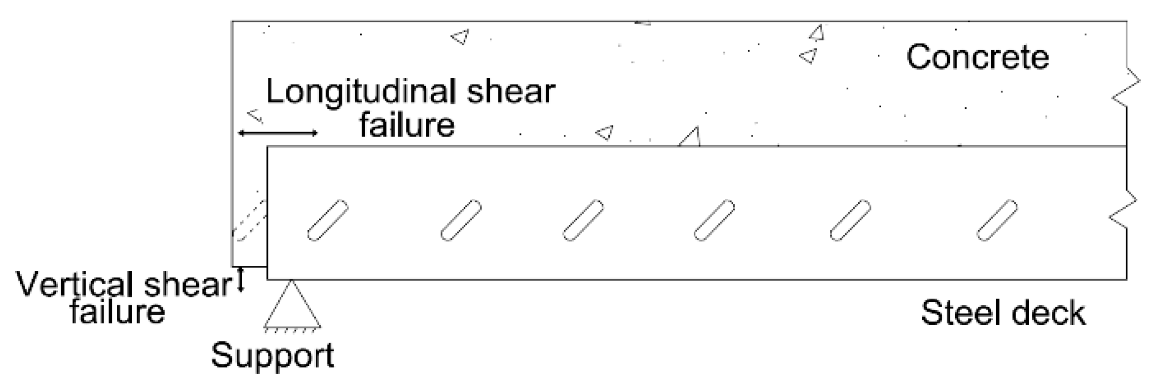
Figure 3.
Failure mechanism of steel decks in composite stage.
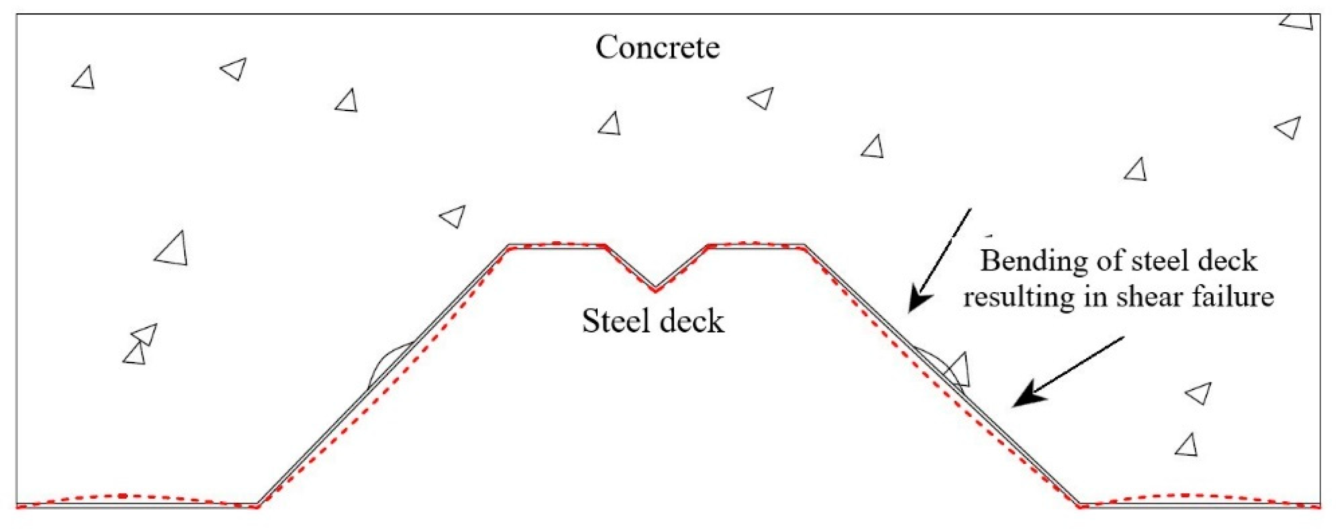
Figure 4.
Bent corrugated sheet.

Figure 5.
Details of the proposed innovative profiles: (a) proposed top-hat section; (b) proposed multiple hat sections; (c) cross-section properties of top-hat section geometry; (d) cross-section properties of multiple hat section geometry; and (e) the possible application of the proposed deck in composite slim-flooring.
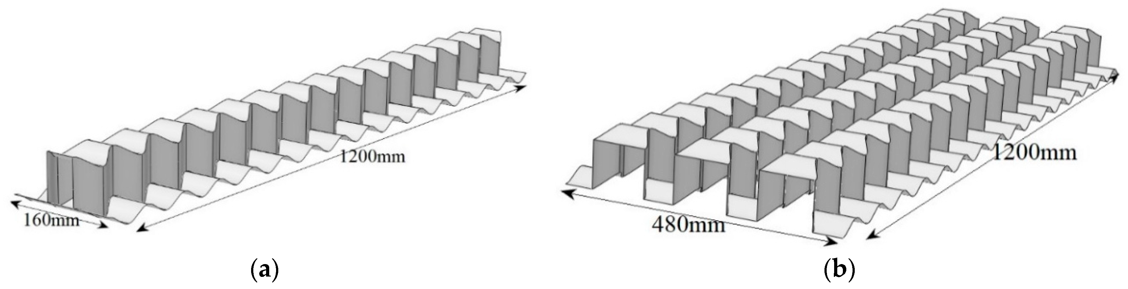

Figure 6.
Details of the tensile test: (a) dimensions of the tensile coupon; and (b) stress–strain curves of the material.
Figure 6.
Details of the tensile test: (a) dimensions of the tensile coupon; and (b) stress–strain curves of the material.

Figure 7.
Details of the experimental bending test of the hat sections: (a) schematic showing a four-point bending test arrangement used to test the hat section; (b) flat timber block at support; (c) bending test of the hat section; (d) corrugated timber blocks for testing B1; and (e) the loss of contact of timber block at support.


Figure 8.
Details of the experimental test of single-span multiple hat sections: (a) schematic showing the single-span test set-up for corrugated multiple hat sections; and (b) the single span deck test set-up before loading.
Figure 8.
Details of the experimental test of single-span multiple hat sections: (a) schematic showing the single-span test set-up for corrugated multiple hat sections; and (b) the single span deck test set-up before loading.


Figure 9.
Details of the experimental test of continuous span multiple hat sections: (a) test arrangement for the continuous span test; and (b) continuous span test.
Figure 9.
Details of the experimental test of continuous span multiple hat sections: (a) test arrangement for the continuous span test; and (b) continuous span test.


Figure 10.
End span test.
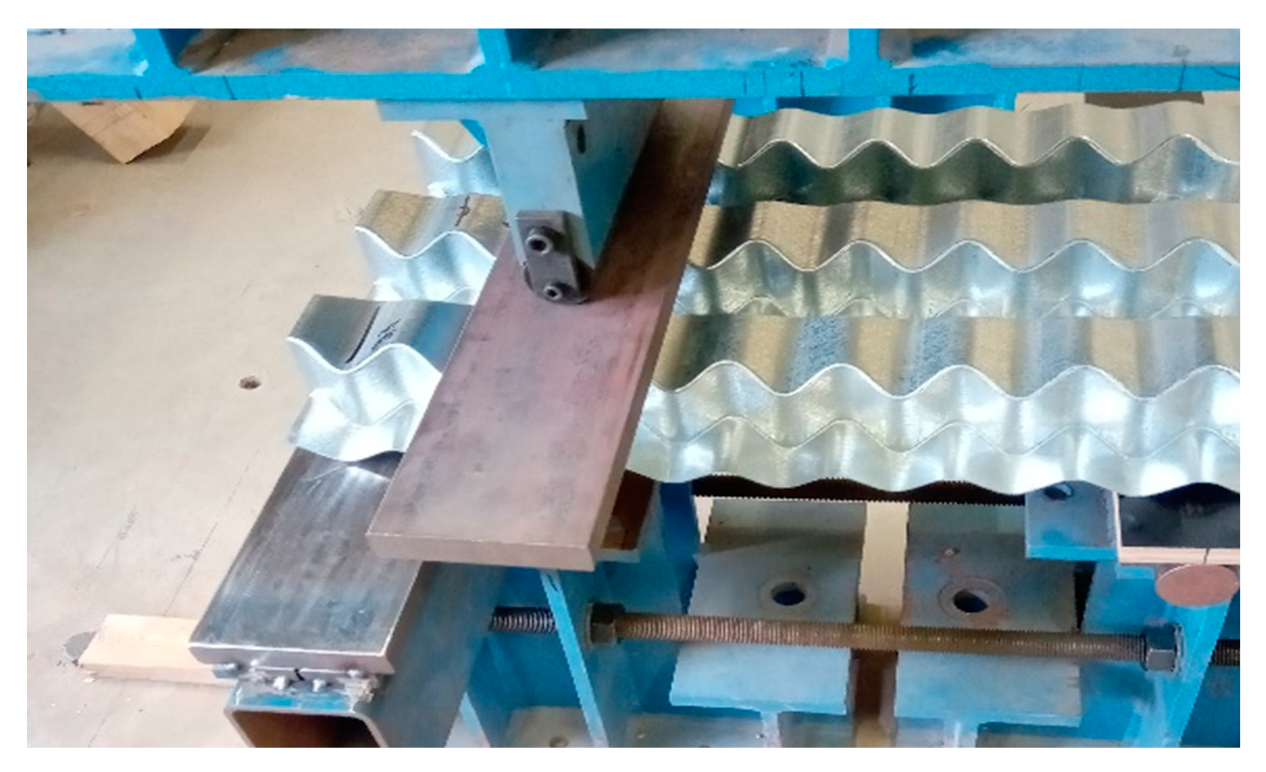
Figure 11.
Failed top-hat section.
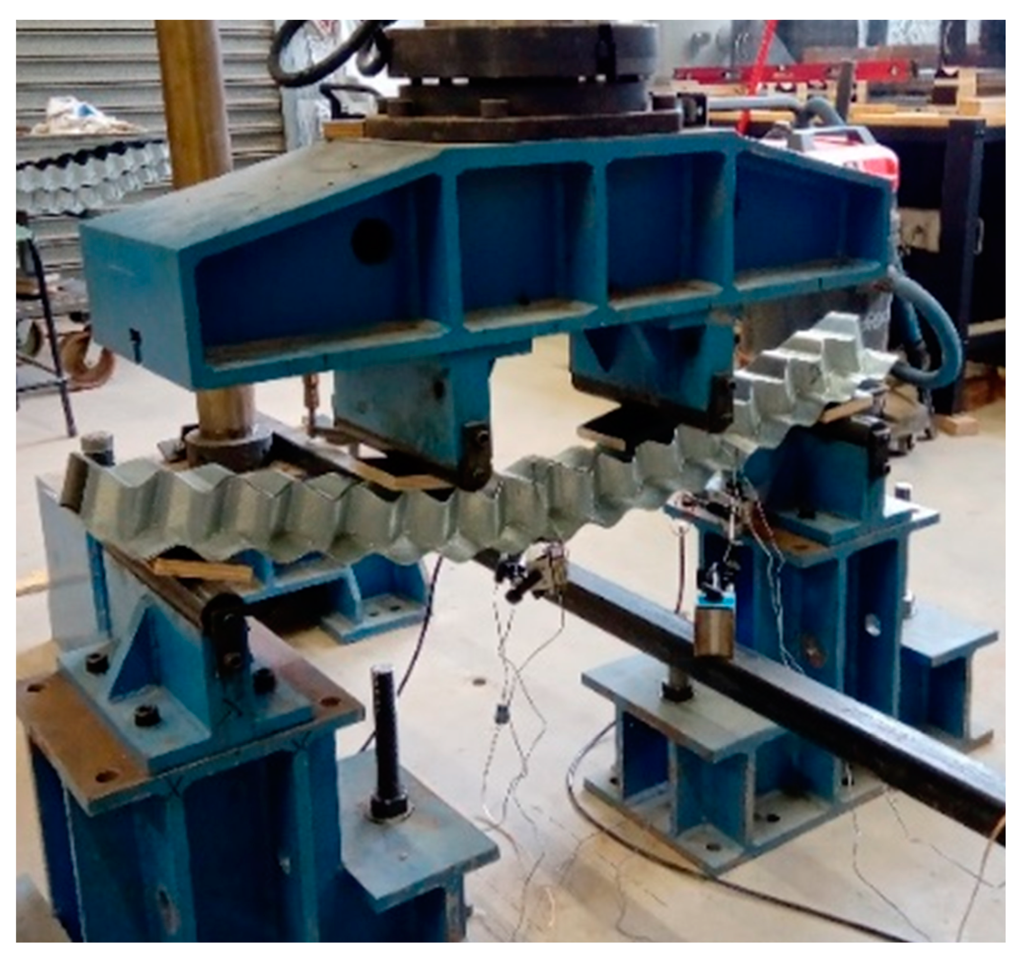
Figure 12.
Load vs. displacement for the corrugated top-hat beams.

Figure 13.
Failure pattern of the tested single-span decks: (a) deformed shape of the deck showing excessive deflection; and (b) local failure around the loading regions.
Figure 13.
Failure pattern of the tested single-span decks: (a) deformed shape of the deck showing excessive deflection; and (b) local failure around the loading regions.
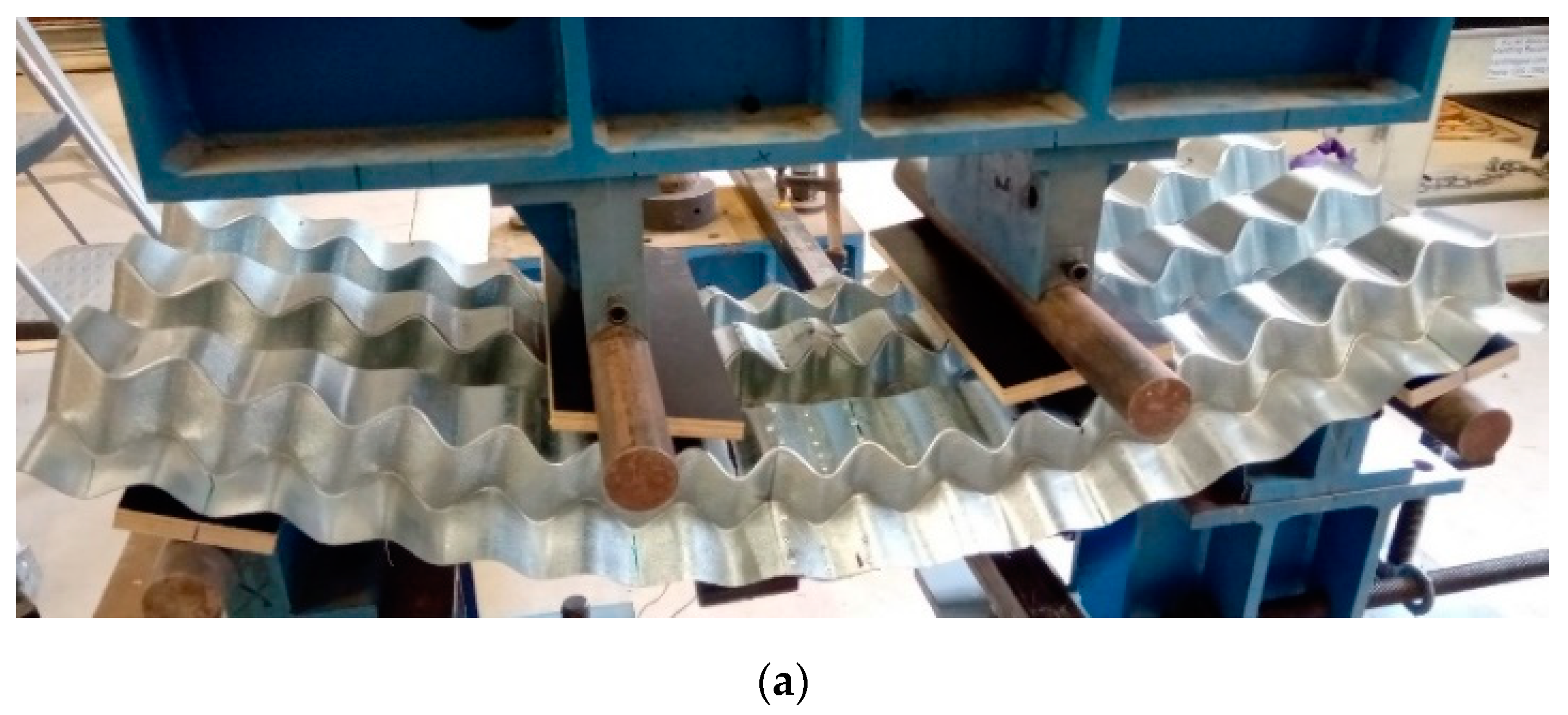

Figure 14.
Load vs. mid-span deflection curves for single span deck tests.
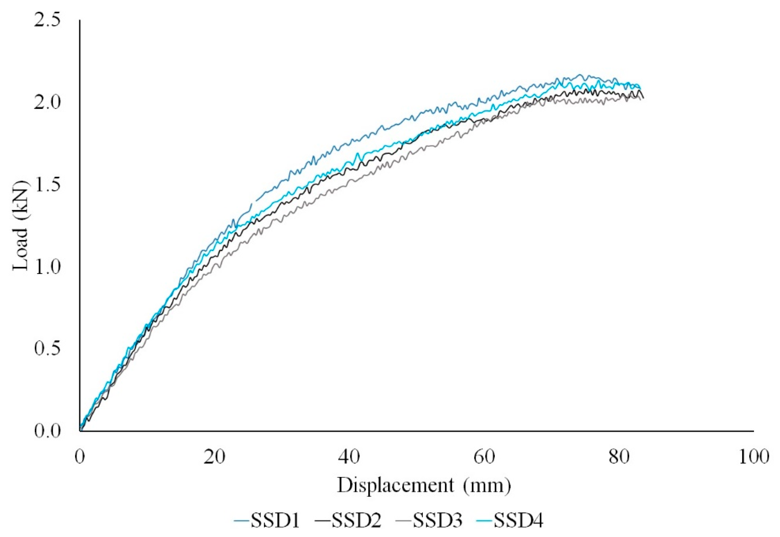
Figure 15.
Results from continuous span deck tests: (a) load vs. deflection curve for CSD; and (b) stress vs. strain curves for CSD close to middle support.
Figure 15.
Results from continuous span deck tests: (a) load vs. deflection curve for CSD; and (b) stress vs. strain curves for CSD close to middle support.

Figure 16.
Failure pattern of the tested continuous span decks: (a) deformed shape of the continuous span deck (CSD); and (b) local squashing observed at internal support.
Figure 16.
Failure pattern of the tested continuous span decks: (a) deformed shape of the continuous span deck (CSD); and (b) local squashing observed at internal support.

Table 1.
Material properties obtained from the tension coupon tests.
| Sample No. | Young’s Modulus E (GPa) | Yield Stress σy (MPa) | Ultimate Stress σu (MPa) | Ultimate Strain εu (%) |
|---|---|---|---|---|
| S1 | 191.07 | 218.08 | 222.52 | 17.53 |
| S2 | 202.06 | 252.64 | 258.58 | 26.66 |
| S3 | 204.33 | 229.51 | 237.61 | 27.25 |
| S4 | 202.38 | 219.80 | 227.49 | 26.05 |
| S5 | 211.81 | 249.90 | 260.52 | 27.55 |
| Average | 202.33 | 233.98 | 241.34 | 25.01 |
| COV | 0.04 | 0.07 | 0.07 | 0.17 |
Table 3.
Experimental and calculated results for individual top-hat sections (experiment group (a)).
Table 3.
Experimental and calculated results for individual top-hat sections (experiment group (a)).
| Beam No. | Ultimate Load Fu (kN) | Experimental Moment Capacity Mu (kNm) | Predicted Moment Capacity Mb (kNm) | Mu/Mb |
|---|---|---|---|---|
| B1 | 0.88 | 0.15 | 0.21 | 0.71 |
| B2 | 0.86 | 0.14 | 0.21 | 0.66 |
| Average | 0.87 | 0.145 | 0.21 | 0.69 |
Table 4.
Experimental and calculated results for single-span decks (experiment group (b)).
| Deck No. | Ultimate Load Fu (kN) | Experimental Moment Resistance Mu (kNm) | Predicted Moment Resistance Mb (kNm) | Mu/Mb |
|---|---|---|---|---|
| SSD1 | 2.05 | 0.34 | 0.48 | 0.71 |
| SSD2 | 2.17 | 0.36 | 0.75 | |
| SSD3 | 2.08 | 0.34 | 0.71 | |
| SSD4 | 2.13 | 0.35 | 0.73 | |
| Average | 2.10 | 0.35 | 0.48 | 0.73 |
Table 5.
Experimental and calculated results for continuous deck tests (experiment group (c)).
| Deck No. | Ultimate Load Fu (kN) | Middle Support Collapse Load Fs (kN) | Reaction Force Rs (kN) | Predicted Capacity Rc (kN) |
|---|---|---|---|---|
| CSD1 | 7.51 | 6.90 | 4.69 | 3.63 |
| CSD2 | 7.45 | 7.20 | 4.88 | |
| Average | 7.48 | 7.05 | 4.78 | 3.63 |
Table 6.
Experimental and calculated results for the end support tests (experiment group (d)).
| Deck No. | Web Crippling Load Fu (kN) | Ultimate Experimental Reaction Rs (kN) | Predicted Web Crippling Load Fend (kN) | Predicted Design Resistance Rend (kN) | Predicted Web Crippling Load Fint (kN) | Predicted Design Resistance Rint (kN) |
|---|---|---|---|---|---|---|
| (As End Support) | (As Internal Support) | |||||
| ESD1 | 8.61 | 6.46 | 2.21 | 1.51 | 5.73 | 3.92 |
| ESD2 | 8.58 | 6.40 | ||||
| Average | 8.59 | 6.43 | 2.21 | 1.51 | 5.73 | 3.92 |
Publisher’s Note: MDPI stays neutral with regard to jurisdictional claims in published maps and institutional affiliations. |
© 2020 by the authors. Licensee MDPI, Basel, Switzerland. This article is an open access article distributed under the terms and conditions of the Creative Commons Attribution (CC BY) license (http://creativecommons.org/licenses/by/4.0/).
Share and Cite
MDPI and ACS Style
John, K.; Ashraf, M.; Weiss, M.; Al-Ameri, R. Experimental Investigation of Novel Corrugated Steel Deck under Construction Load for Composite Slim-Flooring. Buildings 2020, 10, 208. https://doi.org/10.3390/buildings10110208
AMA Style
John K, Ashraf M, Weiss M, Al-Ameri R. Experimental Investigation of Novel Corrugated Steel Deck under Construction Load for Composite Slim-Flooring. Buildings. 2020; 10(11):208. https://doi.org/10.3390/buildings10110208
Chicago/Turabian StyleJohn, Keerthana, Mahmud Ashraf, Matthias Weiss, and Riyadh Al-Ameri. 2020. "Experimental Investigation of Novel Corrugated Steel Deck under Construction Load for Composite Slim-Flooring" Buildings 10, no. 11: 208. https://doi.org/10.3390/buildings10110208
Note that from the first issue of 2016, this journal uses article numbers instead of page numbers. See further details here.