Article

Structural Performance of Arched Space Trusses Using Date Palm Midribs for Light and Cost-Effective Construction in Egypt

1
Department of Architecture, Faculty of Engineering, Ain Shams University, Cairo P.O.11517, Egypt
2
Department of Design and Production, Faculty of Engineering, Ain Shams University, Cairo P.O.11517, Egypt
3
Department of Structural Engineering, Faculty of Engineering, Ain Shams University, Cairo P.O.11517, Egypt
*
Author to whom correspondence should be addressed.
Buildings 2020, 10(6), 106; https://doi.org/10.3390/buildings10060106
Submission received: 15 April 2020 / Revised: 11 May 2020 / Accepted: 30 May 2020 / Published: 3 June 2020
(This article belongs to the Section Building Structures)

Abstract

:
Date palm midribs enjoy a long heritage among rural builders and craftsmen in Egypt for their abundance and low-cost. This familiarity encouraged previous studies to tackle the question of using date palm midribs in wide-span construction to provide simple, quick, cost efficient shaded structures. The design of tri-arched space truss was aimed to utilize date palm midribs in cost-efficient wide-span construction with minimal processing and maximum structural efficiency. However, the validated mechanical properties, the workability, the short-term and the long-term structural behaviors of the system are yet to be investigated. This paper investigates the structural behavior of a proposed tri-arched system using 1:3 scale specimens. The long-term environmental effects are also studied in one of the specimens. The specimens experienced high flexibility and gradual failure. A finite element model was created to predict the behavior of the specimens. The validated model was used to determine the structural behavior of the system with 12 m span. The system was found to be safe under the loads of wind and roofing. This paper is a part of a continuous process of validation that aims to utilize date palm midribs in contemporary wide-span construction to match the spirit of the youth in rural communities.

1. Introduction

Date palms require annual pruning process as a part of their cultivation maintenance. The main benefits of this pruning process are to remove excess leaves in order to facilitate the processes of pollinations and collecting the dates, to allow for better fruit production with higher exposure for sunlight, and most importantly, to collect the residues that can be utilized in many industrial fields [1,2,3]. Those agricultural residues of date palm-based industries support over one million families in Egypt [4]. As shown in Table 1, date palm midribs acquire the highest percentage among the total amount of the products of the annual pruning process of date palms [3].
As a result, date palm midribs have been used in numerous forms of traditional handicrafts and vernacular construction in Egypt since the Ancient Egyptian period [5]. Consequently, a strong technical heritage can still be found in the rural societies in Egypt, to the present day. In handmade furniture (Figure 1a), fruit crates (Figure 1b) and bread boards, midribs girders are punctured and shorter spandrels are hammered and fixed by friction through the punctured holes [6]. Fencing in the rural areas (Figure 1c) usually depends on fixing midribs and whole date palm leaves (the midribs without removing the leaflets) vertically in the soil and reinforcing the fences with horizontal midribs using ropes [6]. The doors in this type of fencing depends on simple midribs lattices. In traditional roofing in the rural areas in Egypt (Figure 1d), date palm midribs are laid over beams made from date palm trunks and thick layers of mud are added over the midribs for thermal insulation [6]. Those example show that date palm midribs are utilized as reliable materials to benefit from their abundance, high renewability rate, and cost-efficiency [6,7].
As realized from the technical heritage of date palm midribs in Egypt, depending on ropes for fastening and using simple friction-based connections were the basic techniques needed when utilizing date palm midribs in the majority of that heritage [2]. Those simple techniques require no extensive preparation for midribs prior to use. This ability of direct use is due to the ability of the peripheral cover of a date palm midrib to resist humidity and direct sunlight [1,8]. Thus, all those characteristics led to the widespread utilization of date palm midribs among the poor rural societies in Egypt, such as in several products for household and vernacular rural housing [6,8]. The know-how behind this surviving heritage still enjoy high popularity among craftsmen in Egypt, which makes it possible to build on this knowledge for further exploitation of the potential of the material [2,9,10].
Subsequently, the structural potentials of date palm midribs were examined in previous studies in order to determine the possibility of using date palm midribs in the construction of light wide-span construction, as a substitute for conventional building materials and imported timber in Egypt [1]. Introducing date palm midribs as a local and cost-efficient material for light wide-span construction would contribute to solving the problem of the lack of shaded public areas that are increasingly needed in order to shelter users from the hot summer mornings in rural areas in Egypt [11].Such manner is clearly inspired by the international trend to rethink construction utilizing bio-based building materials such as bamboo and reeds [12]. However, the main challenge in developing date palm midribs-based construction is to achieve durability, flexibility and sophistication, in order to match the demands of the contemporary youth and restore their faith in local materials [13], while sustaining their simplicity and cost efficiency without complicated connections or excessive industrialization [7,8].
Despite the history of date palm midribs, limited numbers of studies were performed to study their structural behavior and suitability in wide-span construction. Several previous trials of utilizing date palm midribs in wide-span construction were inspired from the spontaneous intellect in the traditional Iraqi Mudhif. An average 13 m-span Mudhif, a traditional building type for social gathering in the marshlands in Iraq, is a simple barrel vault which consists of consecutive arched reed bundles with 500–700 mm diameter [14]. Additional reed bundles are used as purlins to connect the arches together. The design of the date palm midribs vault was inspired by the Mudhif concept, where it depended on building real scale mock-ups of arched date palm midribs bundles planted in the ground consecutively to form a wide-span vault [15], as shown in Figure 2. However, as the date palm midribs bundles were relatively heavier than their reed counterpart, the available manpower led to the decrease of the diameter to only 250 mm instead of the 700 mm diameter of the reed bundles in the Mudhif [15]. This decrease caused high deformations in the arches, which led to the addition of intermediate palm trunks columns, which subsequently reduced the span from the intended 13 m to 3.25 m between the columns [8,15,16]. Nevertheless, the main gain of this trial was maintaining the simplicity of the system where the used date palm midribs were in their original shape without any processing.
Based on this trial, a cross-vault module was developed to cover a food shelter in the United Arab Emirates. The design of the 8 m × 8 m module depended on a grid that consisted of two perpendicular sets of diagonal arched date palm midribs bundles [17]. The cross-vault module created the form of a dome skeleton that was free of intermediate columns. That module was repeated in four rows and four columns to cover the total area of 50 m2. Linen fabrics were tensioned over the arches, as the double curvature of the design meant that the only feasible covering method was covering by fabrics. This design succeeded in covering 8 m spans without intermediate columns. However, the cross vault module restricted the area to be square shaped to create the dome skeleton form. Moreover, the repetition of the arches footings along the perimeter of the covered area restrained the openness and the ability for future expansion of the function inside [8].
On the other hand, other trials focused on the microscopic nature of the date palm midrib, instead of depending on the spontaneous experience such as in the vault and cross vault module discussed earlier. The analysis of the composition of date palm midribs shows the following characteristics:
(1)
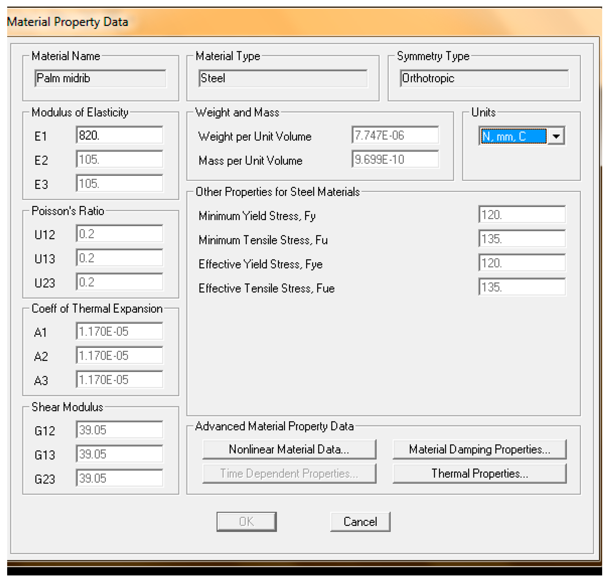
The fibers of the midribs are arranged longitudinally in fibro-vascular bundles [2,18]. Accordingly, the mechanical properties vary according to the direction of those bundles [8]. Those bundles are the solo structural unit in the cross-section, where no cross linking is found between the bundles as the midribs belong to the monocotyledons class [2]. As a result, date palm midribs can be considered as an orthotropic material. In engineering elastic models, orthotropic materials are materials where the properties vary according to three planes in the material: longitudinal, tangential and radial [19]. In date palm midribs, the lack of growth rings leads to the unification of the tangential and radial planes [8]. The orthotropic mechanical properties of date palm midribs, the Baladi species, are shown in Table 2.
(2)
The area and the density of the fibro-vascular bundles vary along the radial line from the highest at the peripheral cover to the lowest at the core area [2]. Accordingly, the cross-section of a date palm midrib can be classified into peripheral cover, transition area and core area.
(3)
At the 1.25 mm thick peripheral cover, the density reaches 1.14 gm/cm3. At the transition area and down to the core area, the density decreases to 0.885 gm/cm3 and 0.823 gm/cm3, respectively [18]. As a result, the tensile strength is the highest at the peripheral cover, at 248 N/mm2, and decreases to 78 N/mm2 and 69 N/mm2 in the transition area and the core zone, respectively [3,18]. This means that sustaining the peripheral cover of the midribs is crucial for the overall strength. Those values, while compared to the corresponding values of the European red pine wood, 78 N/mm2 and beech wood, 97 N/mm2, show promising competitiveness that encourages previous and current researches to introduce date palm midribs as source for wood substitute [2,3,18].
This longitudinal arrangement of the fibers without cross-linking led to the need to employ date palm midribs in a form-active structural element to achieve high structural efficiency [7,8]. The idea of structural efficiency is built on the fact that axial stresses can be more uniformly distributed over the cross-section than in the case with bending stresses [21]. In a form-active element, the design of the element aims to use the strength of the material to the maximum limit within the entire cross-section, by including axial forces to achieve uniform stresses and decreasing bending forces to the least limit [21]. This need for including axial forces and decreasing bending is even more highlighted in the case of date palm midribs, as the longitudinal fibers in the cross-section of date palm material are the only channels that can carry internal forces efficiently in the cross-section, which makes them responsible for the stiffness of the material.
A structural theory that is based on channeling axial forces only is the theory of trusses, which are semi-form active elements [21]. If the loads are applied on the hinged connections of the triangulation, then the sides of the triangles will carry only axial forces with relatively high efficiency of the material [21]. The first trial of using date palm space trusses depended on shredding the midribs into thin strips, than pressing the strips using formaldehyde to produce 100 mm × 100 mm × 1000 mm elements as the chords of the square pyramid units of the space truss [3,7,22], as shown in Figure 3. The designed joinery was fixing the endings of the chords with U-shaped high strength bolts to steel plates. Those steel plates are welded to customized steel boxes. The preliminary experimentation on the space truss design showed promising results regarding the structural potentials of midribs.
However, practically, the manufacture of the joinery designed in the trial was highly complicated, which contradicts the aim of cost-efficiency. Moreover, the removal of the peripheral cover in the process of making the chords decreased the overall structural strength and the natural resistance against the humidity and direct sunlight [20].
In order to overcome the challenges opposed by the complexity of the steel box connectors in the date palm midribs space truss and the removal the peripheral cover of the midribs, the second trial aimed to design a date palm midribs planar truss with simpler joinery and without the need for excessive processing of the midrib elements. The N-truss depended on steel bolts that were driven through the midribs at the intersection between the bracings and the chords. This meant that the chords consisted of two midribs so the spacing in between would host the bracings. One m span specimens were tested and the maximum load carried before failure was 400 kg with the deflection of 43 mm. The failure occurred because of the lateral twisting at the joints [20].
The N-truss trial succeeded in the design of simple steel bolts joinery. However, the validated model of the N-truss showed that the maximum span to be covered by this truss was only 3 m. In spans wider than 3 m, the lateral twisting and the high flexibility of the midribs would cause excessive deflection [20]. Moreover, the natural differences between the values of the expansion and shrinkage between the midribs and the steel joinery, need to be fully investigated in order to design the impact of the interaction between the midribs and the steel joinery on the long-term integrity of the system [7,20].
Consequently, it was realized that the most efficient structural performance of date palm midribs can be obtained by:
(1)
Adopting axial forces-exclusive building elements to adapt to their fibers as the solitary load channel in the cross-section of the material [7,8].
(2)
Choosing the forms of those building elements carefully to adapt to the high flexibility of date palm midribs and to reduce the impact of the deflection on the overall behavior [20].
Both conditions are sustained in arches. The principle of involving axial forces without bending moment happens in the pure form of arches [23]. A single span arch without moment-resistant bases with coplanar supports and a uniform load distribution converts all the internal forces to compression taking a parabolic shape. Hence, a parabolic arch is the compression counterpart of the catenary shape that is adopted by a hung cable under the uniform tension of gravity [23]. Thus, a parabolic arch is a form-active element that acquires the maximum structural efficiency among arches [21]. From that fusion between the structurally analyzed concept of trusses and the spontaneous simplicity of arches, emerged the third trial: the concept of date palm midribs tri-arched space truss, as shown in Figure 4 [8]. A 1:20 scaled physical model, shown in Figure 5, was built to visualize the details of the design and to imitate the construction procedures. The model depended on limited and repeatable prototypes with a high potential for mass production [8]. In addition, the parabolic arched chords hosted simple friction joints that provided sufficient stability to the model [8].
This concept of tri-arched space trusses provided a solution that depended mainly on parabolic chords and simple friction joinery without the removal of the peripheral cover or excessive processing. Moreover, the following aspects can be realized about this concept:
(1)
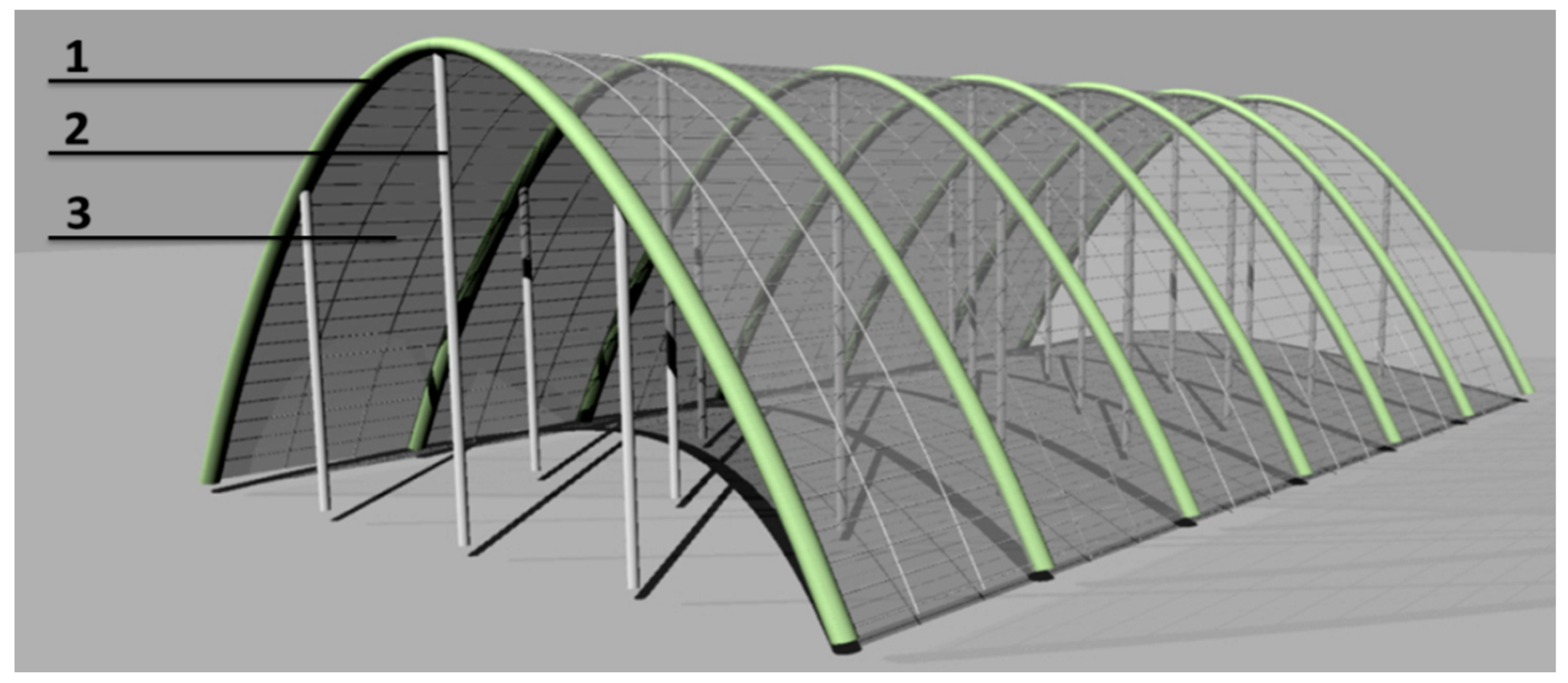
Wide-span coverage: The 3D distribution and the maximum utilization of each element offer high rigidity and stiffness under heavy distributed and concentrated loads. This qualifies the structural system to be used in structures that require high flexibility and wide spans without the necessity of intermediate columns or complicated joinery [24]. Such system can be used for light wide-span multi-purpose halls, traditional open markets, sheds and garages. Those functions are allowed to be built from natural materials, under specific design guidelines, by the Egyptian Code of the Design fundamentals and execution requirements for structures fire protection.
(2)
Mass-production: The stability of a trussed system under loads depends on the self-stabilizing nature of the triangle, the main element of a truss, where the fixed lengths of the sides of the triangle keep its form steady [21]. This means that the predetermined fixed lengths of the repetitive members inside a truss make it simple to depend on prefabrication, which simplifies the process of mass production [8].
(3)
Flexibility: The basic truss action can be sustained even with the simplification of using continuous members through the joints. Those members, usually the chords, can reduce the truss deflections slightly but will not restrain the free deformation of the truss if the continuous members are flexible enough. This flexibility is required so that when the vertical loads on the truss lead to tension on the bottom chord, for instance, the chord and the unrestrained supports can take the deformation safely [23]. This characteristic is highly required when dealing with a material of high deformations such as date palm midribs [7].
(4)
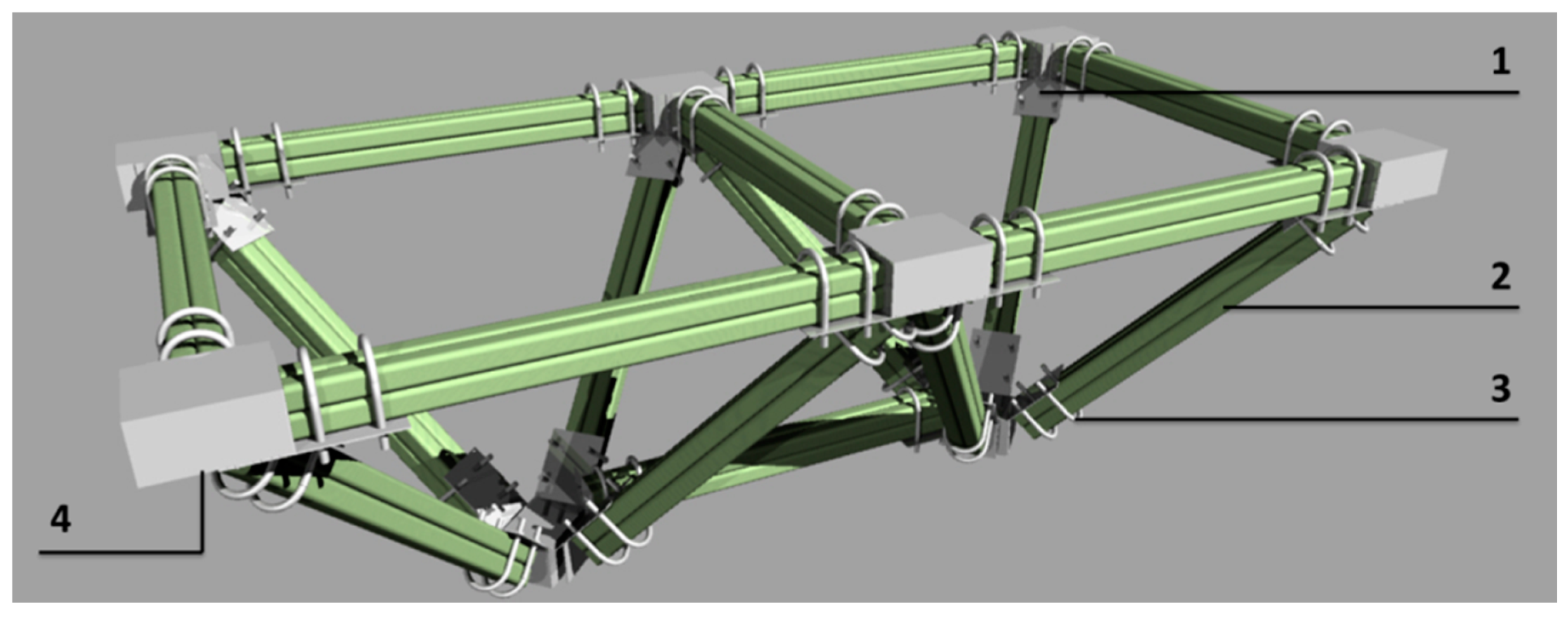
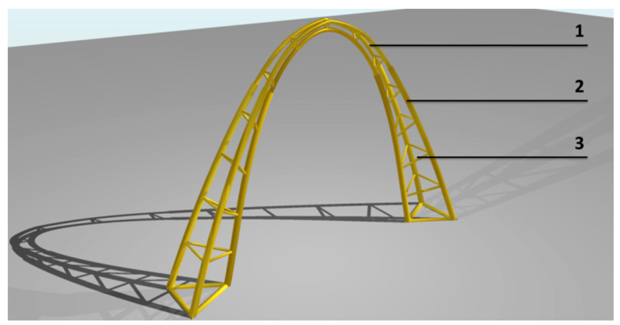
Joinery simplicity: By shaping the chords of the truss to be parabolic arch, the internal forces in the arched chords would be exclusively compression [23]. This compression of the bundles would be exerted on the triangulation members inserted with friction into the chords. This friction-based joinery can be assumed to be hinged joints with no moment resistance, as no adhesives are used to resist moment.
(5)
Cost-efficiency: using date palm midribs in their natural form without excessive processing, depending on friction joinery without customized connections, and employing simple building sequence with moderate manpower [8] contribute to decreasing the overall cost of the system relatively while compared to conventional structures made of steel and concrete or imported timber.
Subsequently, the concept of date palm midribs tri-arched space truss was found to balance between respecting the curved and lean nature of the midribs by shaping the chords to be parabolic bundles, adhering to the midribs simple heritage and the inherited techniques by using friction joinery and robes, and employing form active structural elements such as trusses and arches. Thus, the objective of this article is to determine the structural efficiency and the workability of the date palm midribs tri-arched space truss system for light and cost-efficient wide span construction in Egypt.
Accordingly, the following hypothesis was generated: “Using date palm midribs bundles as parabolic truss chords and depending on simple friction joinery provide sufficient stability to the date palm midribs tri-arched space truss system under its own weight, standard roofing and extreme wind loads while covering the span of 12 m”.
In order to test this hypothesis, the workability of the construction details, the structural behavior, and the long-term effects are to be investigated in this article according to the methodology that is illustrated in Figure 6. This methodology aims to achieve a validated finite element method (FEM) model to predict the structural behavior of date palm midribs tri-arched space truss at the span of 12 m.

2. Material and Methods

In order to undertake experimental testing to investigate the structural behavior of date palm midribs in the proposed system, three scaled testing specimens were constructed for the testing in the concrete laboratory in the Faculty of Engineering, Ain Shams University in Cairo, Egypt.

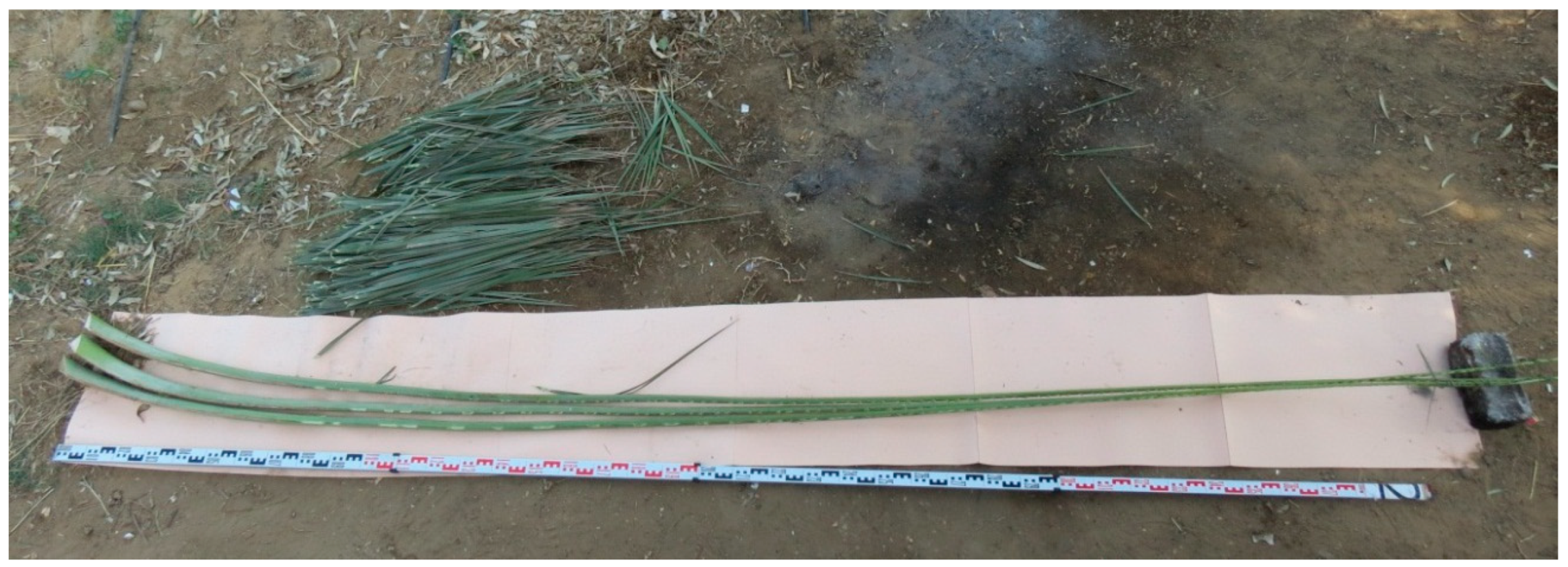
2.1. Shape and Preparation of Date Palm Midribs

A date palm midrib is the longitudinal stem of a whole date palm leaf, on which the leaflets are based as shown in Figure 7. At the base on the trunk, the cross-section of a midrib is triangular and becomes narrower and denser towards the end of the midrib [2]. The length of a midrib varies according to the species of the date palm, ranging from 4 m to 6 m [9]. Only excessive and dry midribs are removed during the pruning process, leaving the midribs that are required for healthy photosynthesis in the palm.
The preparation of date palm midribs is relatively simple. The removal of the leaflets is done manually, then the midribs are left to dry in the air, either vertically or horizontally. In vertical drying, the midribs are collected in bundles and laid to a wall for 2–3 weeks to dry. However for applications that require straighter midribs, the midribs are laid on the ground in layers for 4–6 weeks [8]. For the specimens in this article, the vertical drying method was used to sustain the natural bent shape that was needed to create the arched chords. Finally, the midribs were divided into groups where the midribs of each group were cut to the needed lengths. The needed lengths were obtained by scaling the actual lengths from the original 12 m span design in order to imitate the details of the overlapping in the arched chords and to study their impact on the structural performance. The thick ends and the final thin ends of the midribs were discarded to be used then as a fuel source.

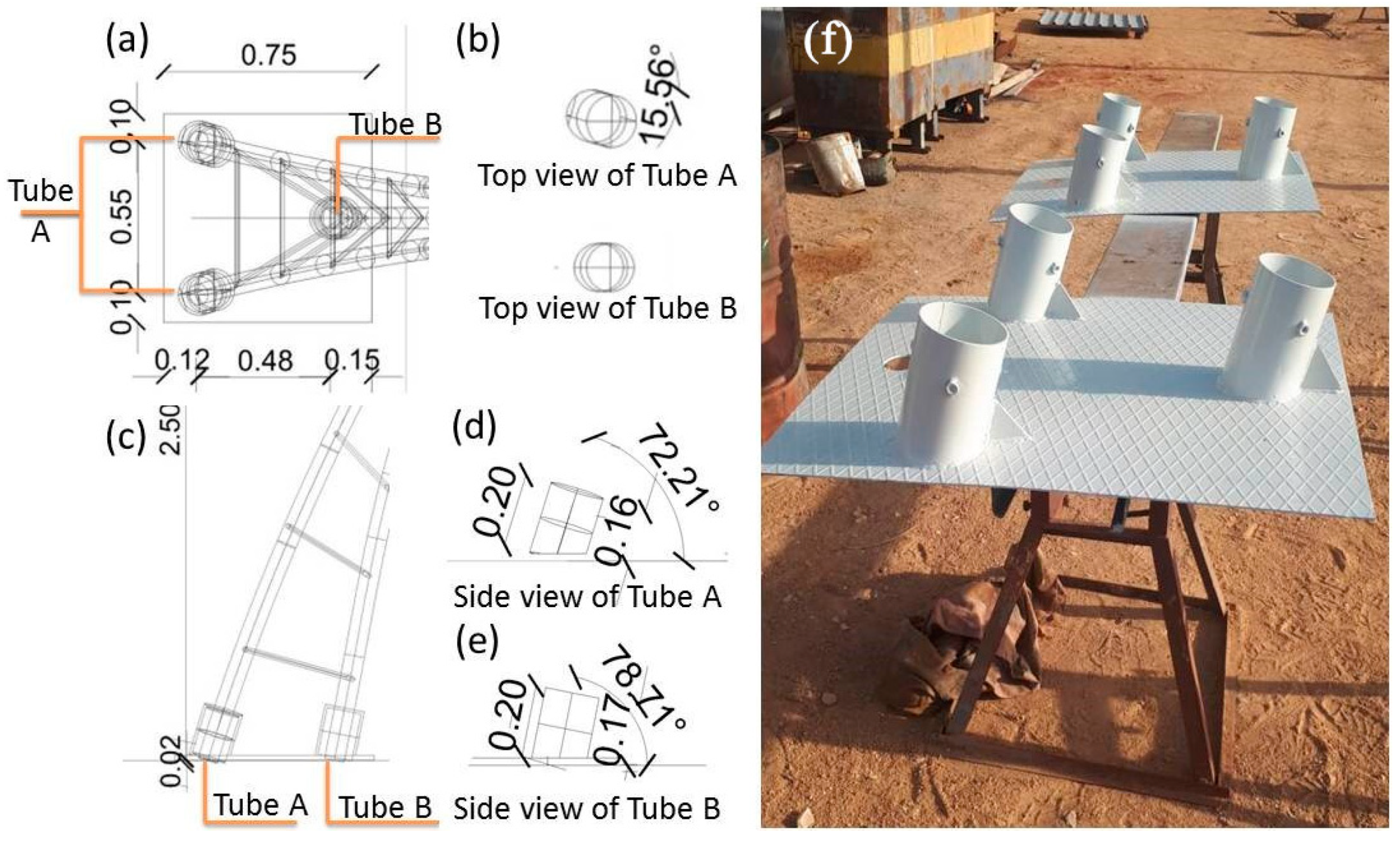
2.2. Design of the Test Specimens

The span of the specimen was 3.3 m and the height was 2.50 m according to the limitations of the machinery available in the laboratory. As stated previously, each specimen consisted of three parabolic arched chords made from 12% moisture content date palm midribs. The ropes used for binding the midribs bundles were local kenaf ropes. The bracings joinery depended on friction connection in between the midribs of the bundles without the use of any adhesives. The foundations were designed to be prefabricated steel base in order to facilitate transportation of the specimens. The date palm midribs used belonged to the Baladi species, which is a hybrid soft cultivar species of date palms that grows along the Nile Valley in Upper Egypt [4]. The dimensions of a specimen, according to the limitations of the machinery in the laboratory, were as shown in Figure 8.
Regarding the base, a customized base was built of stainless steel with special cylindrical tubes to simulate underground precast concrete foundation. The base, shown in Figure 9, was prefabricated to be used for all specimens with the specific angles and dimensions that would guarantee the exact ratios needed to build the specimens as identical as possible. The dimensions are shown in Figure 9a. The base depended on two prototypes of the tubes, tube A and tube B. The prototypes differed in the angles of horizontal rotation and vertical inclination, as shown in Figure 9b–e. Both prototypes shared the same the diameter of 15 cm. Prior to experimentation, the bases were both welded to a C-channel beam at the span of 3.30 m in order to facilitate transportation of the specimens, as shown in Figure 9f.

2.3. Building Procedures of the Specimens

The total process of building the first specimen depended on a team of four date palm midribs fencing workers and two crate makers and took two full working days. On the first day, the four fencing workers were hired to build the specimen. On the second day, only the two crate makers were hired to rebuild and repair the asymmetries of the specimen. The second and the third specimens were built by the three crate makers. Each specimen was completed in less than four hours. According to the crate makers, the specimens were simple to build. They reported that the know-how and the skills of building the specimens were easily grasped once their first trial was completed.
The third specimen was chosen to become a long-term specimen, where the duration between building and testing the specimen was six months to determine the effect of time and creep on the structural behavior. A summary of the procedures was as follows:

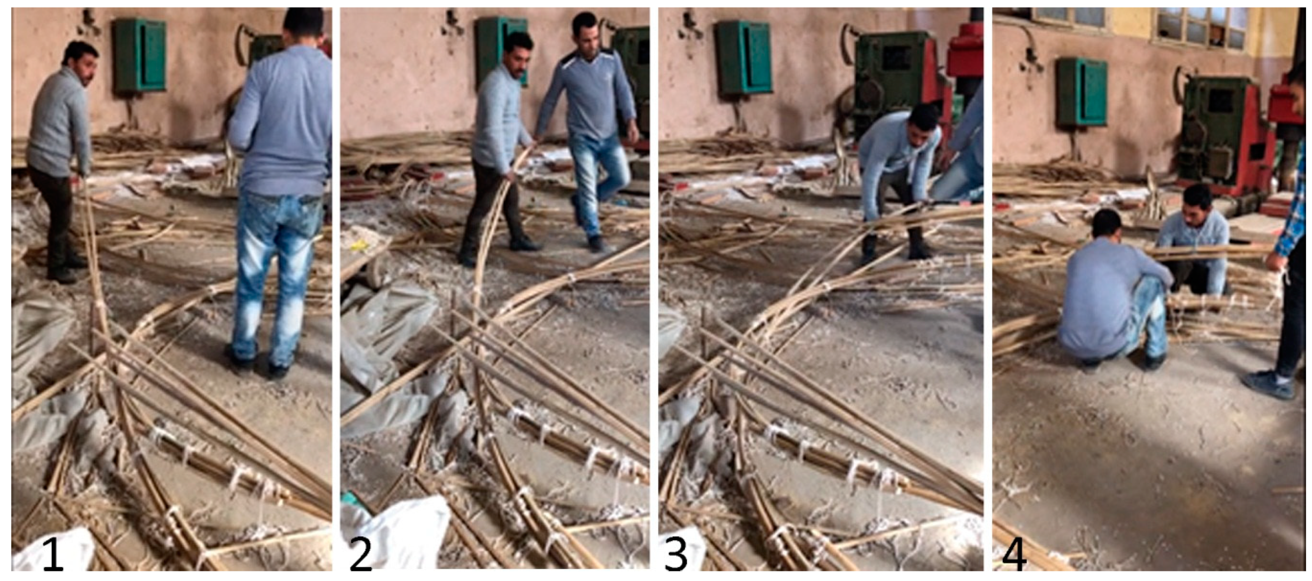
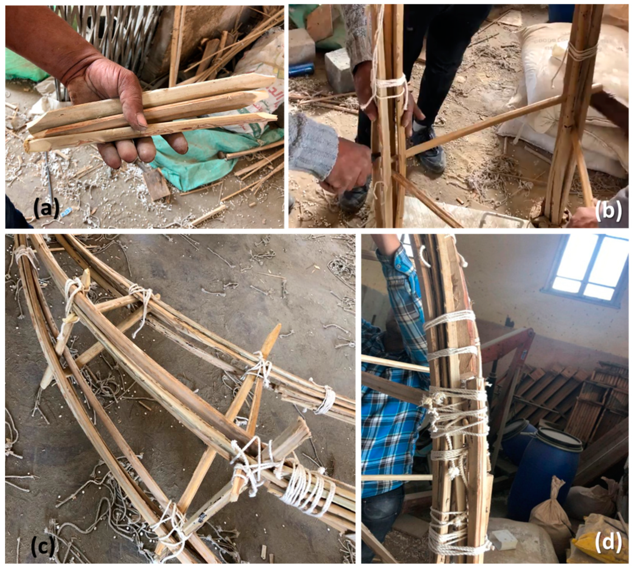
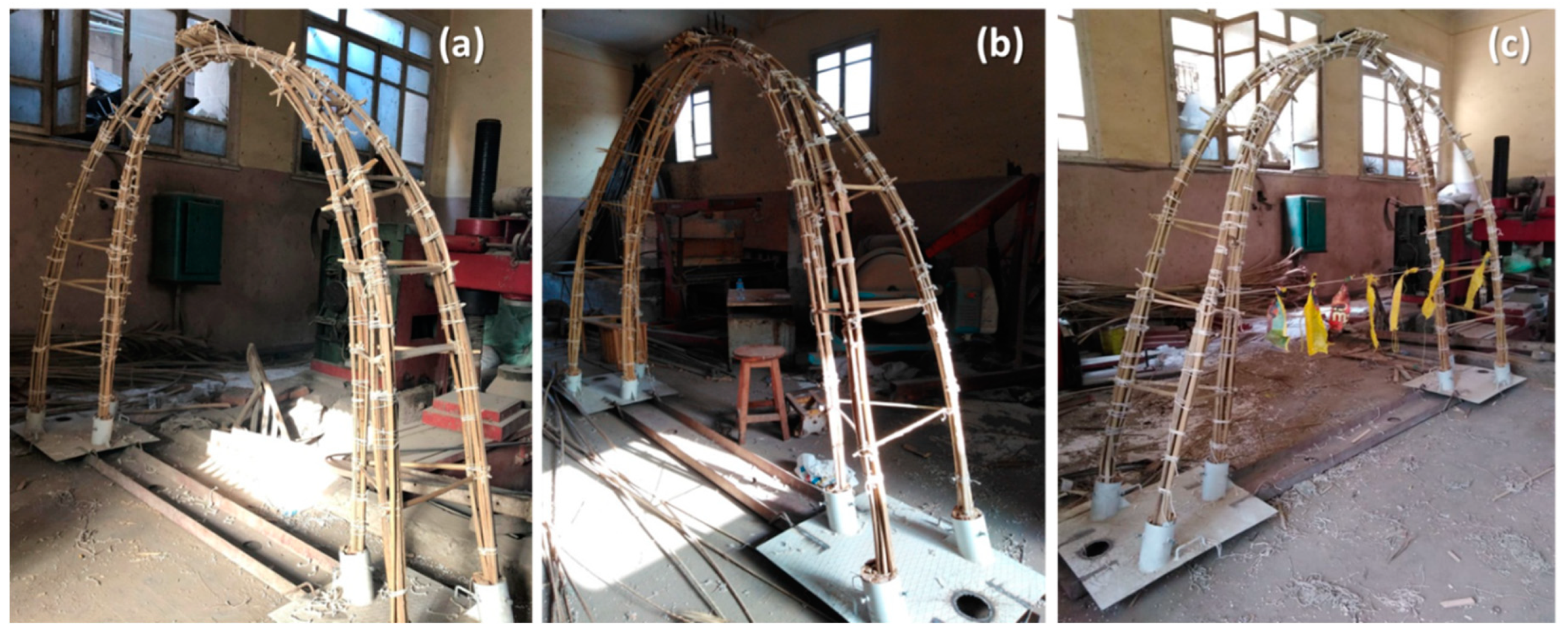
2.3.1. Building the Arched Chords

Each arched chord consisted of four midrib elements cut for the same length for the middle bundle, 8 midrib elements cut for the same length for the two bottom bundles, and eight midribs cut for the same length as additional elements to increase the cross-section of the two bottom bundles. Hence, the higher arched chords are identical. Therefore, the three arched chords required the preparation of 6 groups where all the elements of each group were cut to the same length.
In the first specimen, the chords were built using the full-length bending method, as shown in Figure 10. Three date palm midribs elements were tied with the designed overlap to make the full-length first bundle using local kenaf ropes. Then, the bundle was bent and inserted into the cylindrical tubes in both bases and scraps from the trimmed pieces were inserted around the bundles to begin to tighten the grip inside the cylinders. At first the bundle was bent easily, however the middle midrib element cracked announcing the failure of the first attempt (Figure 10a). The cracking was assumed to occur due to the fragility of the cross section of the bundle in the middle. Therefore, another trial was made by bending each 2 full-length bundles together instead of bending each bundle individually (Figure 10b). Hence, each arch would consist of 4 bundles. Then the other two bundles were bent and tied to the first pair (Figure 10c). Then additional scraps were hammered into the cylindrical tubes to fasten the cylinders to make the base as stiff as possible. However, it was realized after completion that the natural variance on the ability of bending between the midribs in the middle bundles led to severe asymmetry in the structure, as shown in Figure 10d.
Therefore, although the completed specimen was sufficiently sturdy, the asymmetry of the top bracings and the difference between the heights and inclinations of the arches required using another method in building the chords. This ability of readjustment was provided thanks to the mechanical details of the structure that were adhesives free.
As a result, the crate makers, based on their experience in friction-based joinery in making crates and cages from date palm midribs [6], suggested using the segmented bending method instead of bending full-length bundles to guarantee the symmetry of the structure. In order to modify the structure, the middle arches were untied and the bottom bundles were strictly fixed in the cylindrical tubes by hammering more midribs pieces into the cylindrical tubes around the bottom bundles. The middle bundle was designed to consist of two halves, where each half consisted of two midribs. Since the cross-section of a midrib becomes narrower along the distance from the pair, each half of the middle bundle was made by tying the base of the first midrib to the end of the second midrib. The first half of the middle bundle was fastened by ropes on one side of the pre-fixed bottom bundle, bent by a worker as he walked, and fastened to one side of the second bottom bundle, as shown in Figure 11. The same steps are repeated on the other side of the bottom bundles, and then the two halves (four midribs) of the middle bundles are tied together at moderate intervals. The completed arches (Figure 12a) and the overlapping area (Figure 12b) showed more unified design with fewer deformities than in the first method.
As to be shown in the following sections, the failure was concentrated on the middle bundles of the specimen. Thus, the lower bundles were still intact and available to be reused in the following specimens in order to prove the reusability of the system elements due to the friction-based adhesive-free joinery.

2.3.2. Installing Bracings and Additional Members

The bracings consisted of six groups, where each group consisted of six midrib elements cut to the same length to form two equilateral bracing triangles. Firstly, the ends of the bracings were pruned and sharpened (Figure 13a). Secondly, the workers used a chisel to open a space in between the elements of the bundles (Figure 13b). Thirdly, each bracing was pushed using a mallet through the openings in the bundles (Figure 13c). It was clear that the compression inside the arches caused high friction which led to that the process of inserting the bracings to be forceful, which accordingly minimalized the threat of dismantling. Fourthly, ropes were used to fasten the bundles before and after each inserted bracing into the bundles to protect from loosening. Finally, the sharpened ends of the bracings were trimmed after securing the exact needed lengths in between the bundles. In addition, extra supports at the bottom of each arch were added to increase the cross-section of the bottom cross-section than the middle cross-section (Figure 13d). The completed specimens are shown in Figure 14.

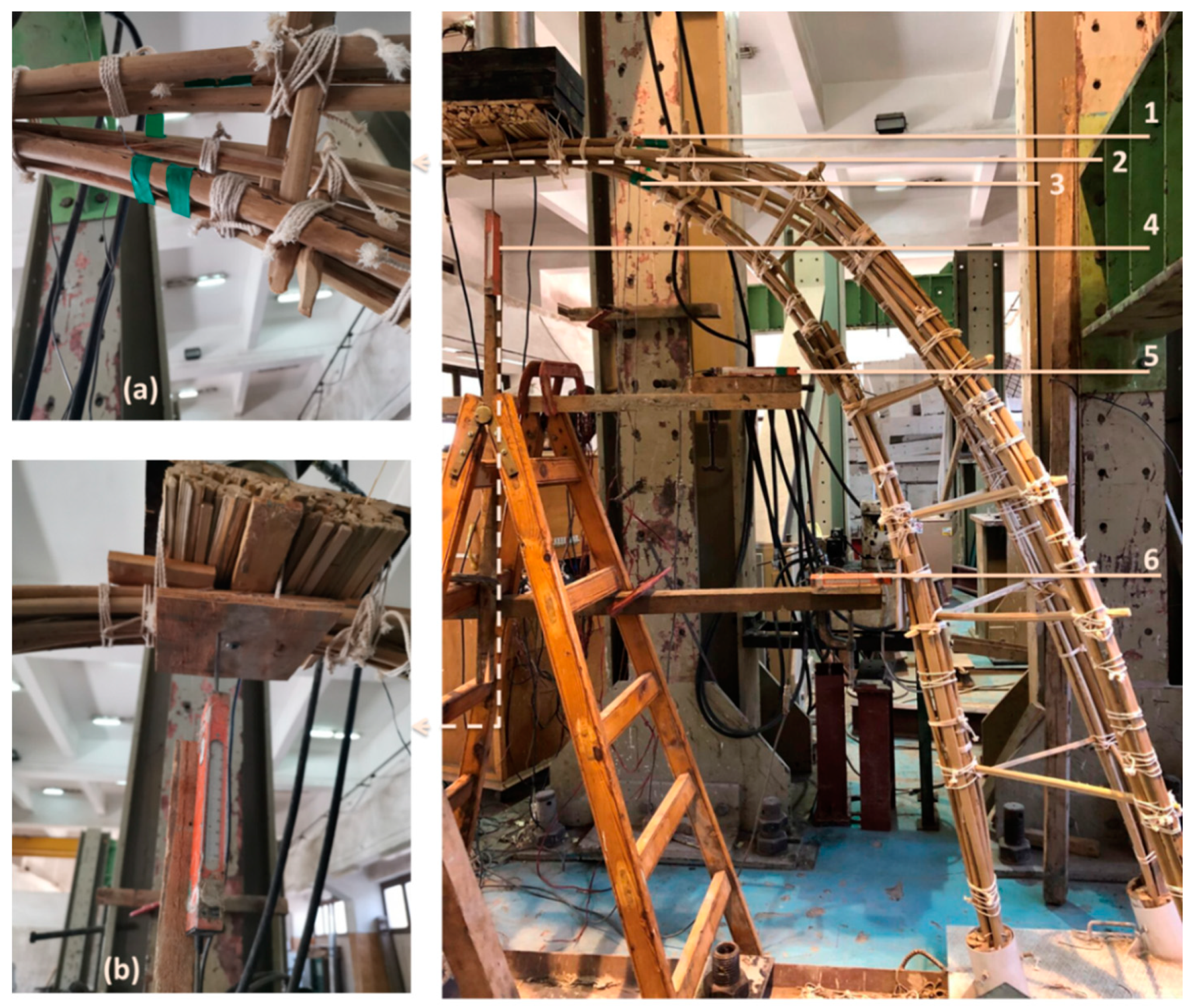
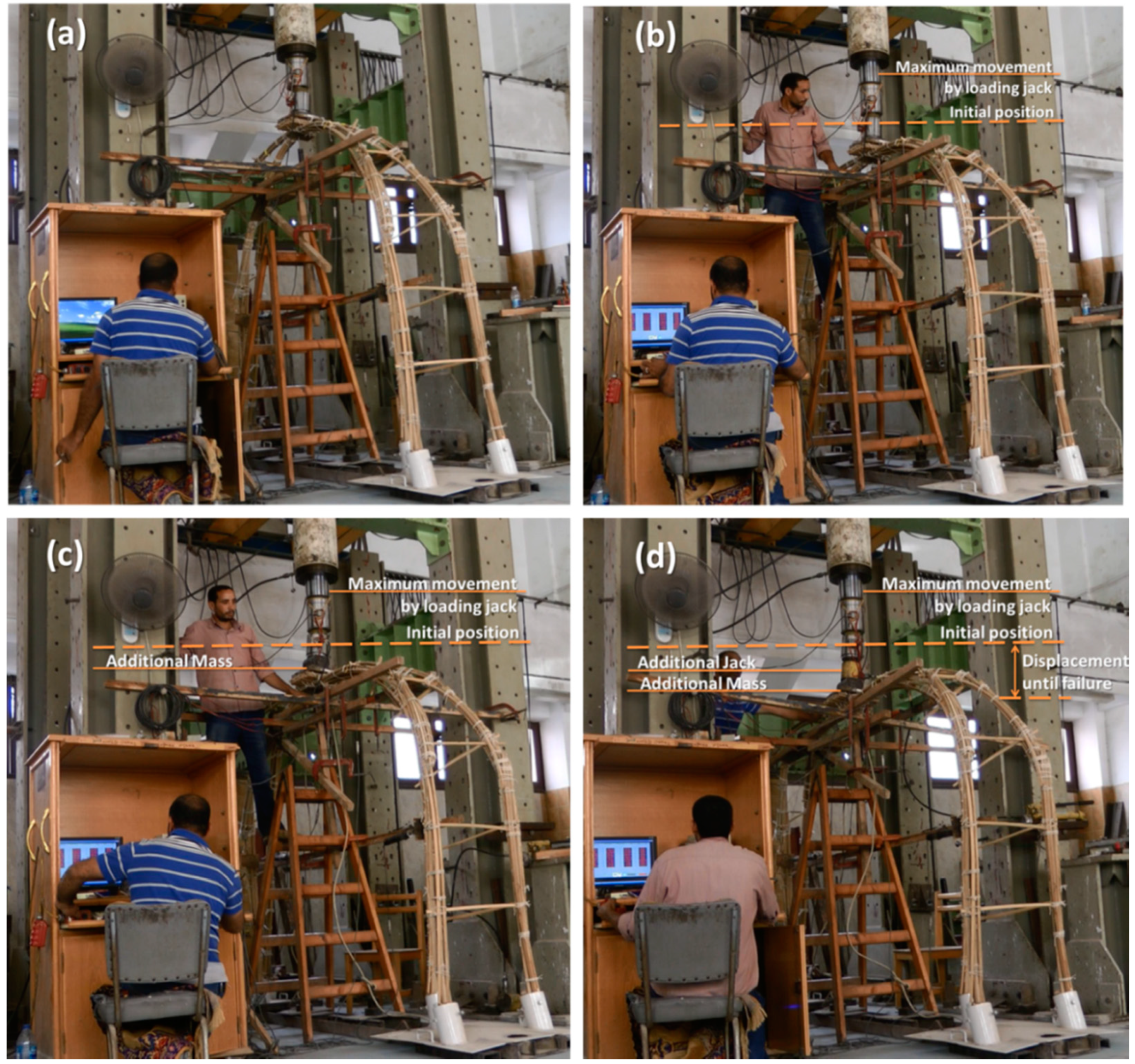
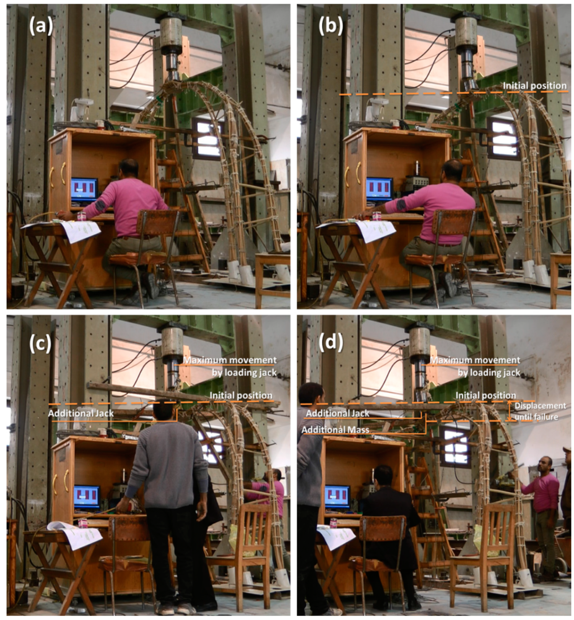
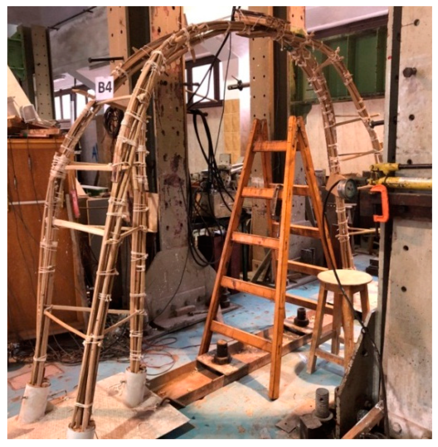
2.4. Test Setup and Instrumentation

One vertical linear variable differential transformer (LVDT) and four horizontal LVDTs were mounted on both sides of each specimen to measure the displacement during the vertical loading. Three strain gauges were mounted on the top portions of the arches of each specimen to measure the strain during the vertical loading. Details of the instrumentations are shown in Figure 15.

3. Results and Discussion

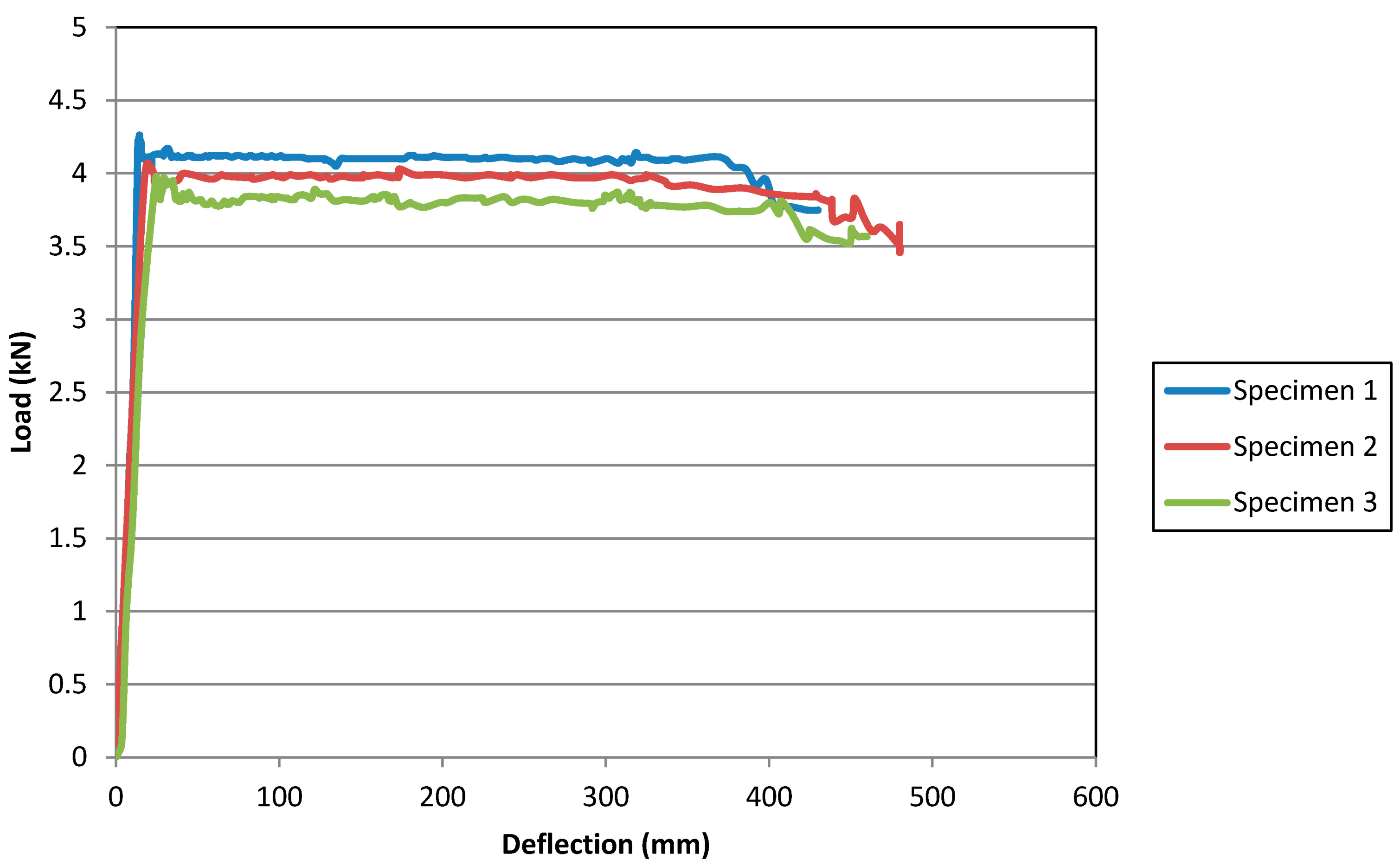
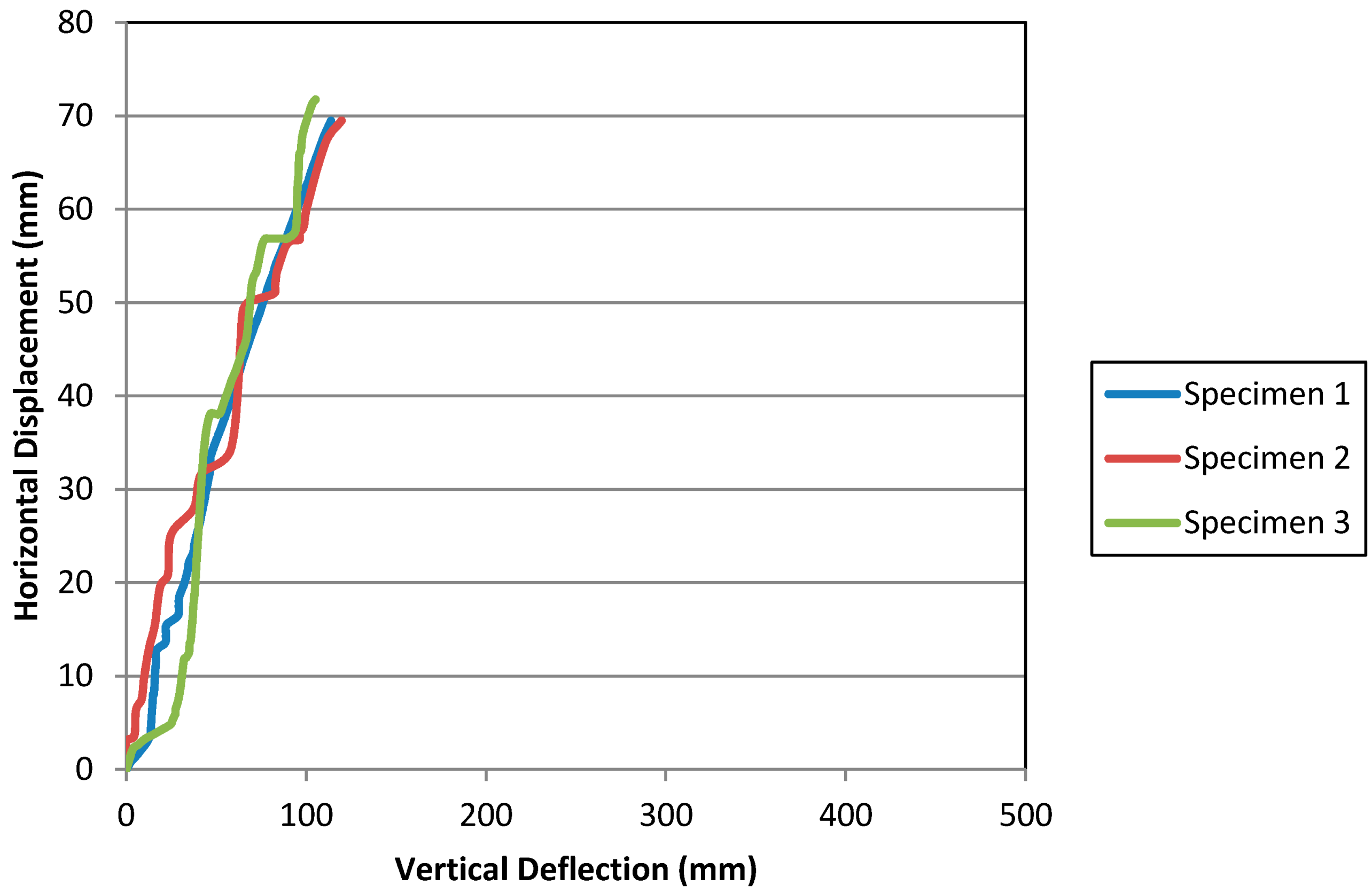
3.1. Experimental Program Results

The specimens demonstrated high ductility as predicted form previous experience with date palm midribs. The detailed experimentation sequences of the specimens were as follows:

3.1.1. Performance of the First Specimen

In the first specimen (Figure 16a), the experimentation sequence was still to be explored. The date palm midribs demonstrated high flexibility more than predicted, adapting to the increasing vertical load by continuous stretching. The main loading jack completed its maximum movement of 250 mm where the middle bundles of specimen stretched and descended steadily without failure (Figure 16b). As a result, it was decided best to fix the current height of the specimen in order to release the jack and allow for the addition of an extra height to add to the vertical displacement of the main loading jack (Figure 16c). The test was resumed and after more deformations, successive sounds of cracking were heard, until the ultimate failure above the overlap area ( Figure 16d). After the test was concluded, the load was released and it was observed that the specimen returned to its original shape despite the local failure in the members.

3.1.2. Performance of the Second Specimen

In the second specimen (Figure 17a), the loading jack reached its maximum movement, 250 mm, while the specimen remained intact (Figure 17b). Wooden planks were fixed to the loading frame in order to maintain the displacement while the loading jack was released and additional mass with the height of 80 mm was added.
Still, the loading jack reached the maximum movement for the second time safely although the middle bundles lost most of the parabolic curvature (Figure 17c). The current displacement was maintained by re-adjusting the wooden planks. The loading jack was released and a hydraulic jack, with the height of 120 mm, was added to manually control the extension of the jack closely until failure. The loading jack reached the maximum movement for the third time. However, the failure could be visibly seen after extending the hydraulic jack for 30 mm (Figure 17d). Similar to the first specimen, the second specimen also returned to its original position after the release of loading.

3.1.3. Performance of the Third (Long Term) Specimen

The third (long-term) specimen (Figure 18a) featured a similar behavior. The loading jack reached its maximum movement safely (Figure 18b), and then, the current displacement was maintained by the use of horizontal wooden planks in order to release the loading jack and add the hydraulic jack. The testing was resumed and the loading jack reached its maximum movement for the second time with no sound of cracking or visual cracks reported although the middle bundles were found to be almost flat (Figure 18c). The current displacement was maintained, the jack was released and the additional mass was added. The maximum movement of the loading jack was reached for the third time, but with repetitive sounds of cracking. The failure was reported during the first attempt to extend the hydraulic jack (Figure 18d). Despite being exposed to weather, the third specimen also returned to its original shape after the release of load, indicating a low effect of long-term factors.

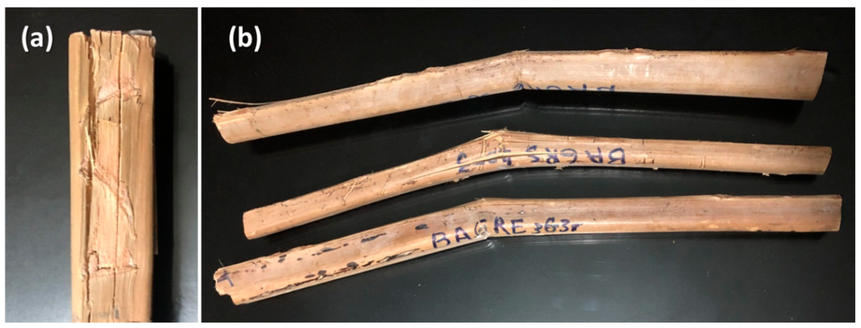
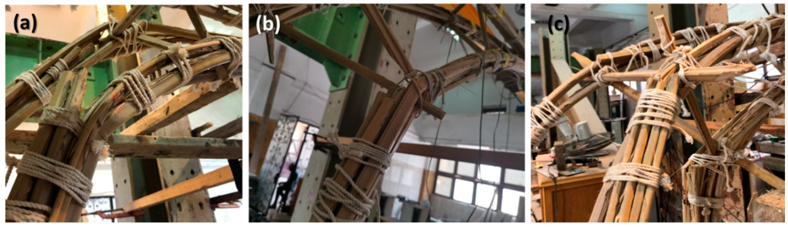
3.1.4. Failure Analysis

The failure was found to be gradual without sudden breaking. The final form of the specimen, after failure and before releasing the loads, showed that the middle bundles became flatter than before, with the area around the loading pallet lower than the rest of the middle bundles, as shown in Figure 19. The actual failure was found in the middle bundles and above the overlap area in the middle bundles. This failure, however, still allowed the specimen to return to the initial form after releasing the loads at the end of testing Figure 20.
The failure at the middle bundles was found to take the form of few narrow longitudinal cracks that resembled the failure patterns reported in the tension testing of date palm midribs previously as shown in Figure 21a [16,20]. Such type of failure occurs because of the tensile overstressing on the peripheral cover of the date palm midribs. This overstressing leads to the failure of the peripheral cover to firmly contain the vascular bundles in the peripheral cover, transitional and core areas of the midribs, which leads to the disassociation of the fibers and the formation of the longitudinal cracks. In summary, this type of failure in the specimens required extremely careful inspection to detect and showed gradual and slow progress.
On the other hand, the failure at the overlapping area was more distinguished and influential on the structural behavior of the specimens. The failure demonstrated at the overlapping area showed breakage at the middle bundles right above the end of the overlap. This breakage type of failure was reported previously as the failure pattern in the bending testing of date palm midribs, as shown in Figure 21b [16]. The vertical loading at the top of the middle bundles gradually reduced the arched shape of the bundles. As a result, the middle bundles tended to expand while still attached to the bottom bundles in the overlapping area. On the other hand, the firmness of bottom bundles was growing along the increasing compression that was generated from the resistance of the natural parabolic shaping to the vertical loading and the solid fixation into the base. Subsequently, the resistance of the bottom bundles to bend enough to accommodate the increasing expansion of the middle bundles led to the generation of a focused bending, and ultimately, the formation of a breaking failure in the middle bundles. Thus, it was found that although under the normal circumstances the parabolic arches contain exclusive axial compression, bending is generated in the arches under extreme loading. In summary, the progress of this type of failure in the specimens was slightly faster and more crucial than the longitudinal cracks and declared the end of testing. The failure of the first, second and third specimens are shown in Figure 22.

3.1.5. General Behavior

The load versus displacement curves for the three specimens is illustrated in Figure 23. The three specimens showed a highly ductile behavior. The specimens were able to sustain the total load with an increase in deformation without a reduction in capacity followed by a gradual strength loss due to failure of members of the truss. As mentioned earlier, the specimens restored their original shape after the presumed failure, which indicates that the specimens could be easily repaired if needed. The capacities of the three specimens were 4.26, 4.06, and 3.97 kN, respectively. The ultimate deflections of the three specimens were 430, 480, and 460 mm, respectively. The results show a consistent behavior of the specimens, even for the long-term specimen, indicating that the structural behavior is not highly affected by atmospheric exposure.
The relation between the vertical deflection and the horizontal displacement at the top and bottom LVDTs for the three specimens are illustrated in Figure 24 and Figure 25, respectively.
The figures show that with vertical loading, the arches have both vertical and outwards horizontal displacements. The values of the horizontal displacements at the top LVDT are around 60 to 70% of the vertical deflection and at the bottom LVDT are around 30 to 40% of the vertical deflection. This is the main reason for the high ductility of the arches, since they resist the vertical load with two dimensional large displacements.
The relation between the strain and deflection is illustrated in Figure 26. The strain increased with the increase of loading. This indicates that the vertical load, despite being constant, is transferred to the members gradually with the increase in deformations so that the overall equilibrium of the structure is maintained. This explains why the load remained constant during the experiments and did not decrease until the onset of members’ failure. It should be noted that the strain gauges malfunctioned before reaching the total deflection. The rough nature of the peripheral cover of the midrib made it harder to attach the strain gauges and caused the early malfunctioning.

3.2. Analytical Program Results

According to the experience gained through working on the detailing of the specimens, a digital structural analysis was undertaken in order to validate the structural behavior of date palm midribs in the given design and to predict the structural performance in the 12 m span design.

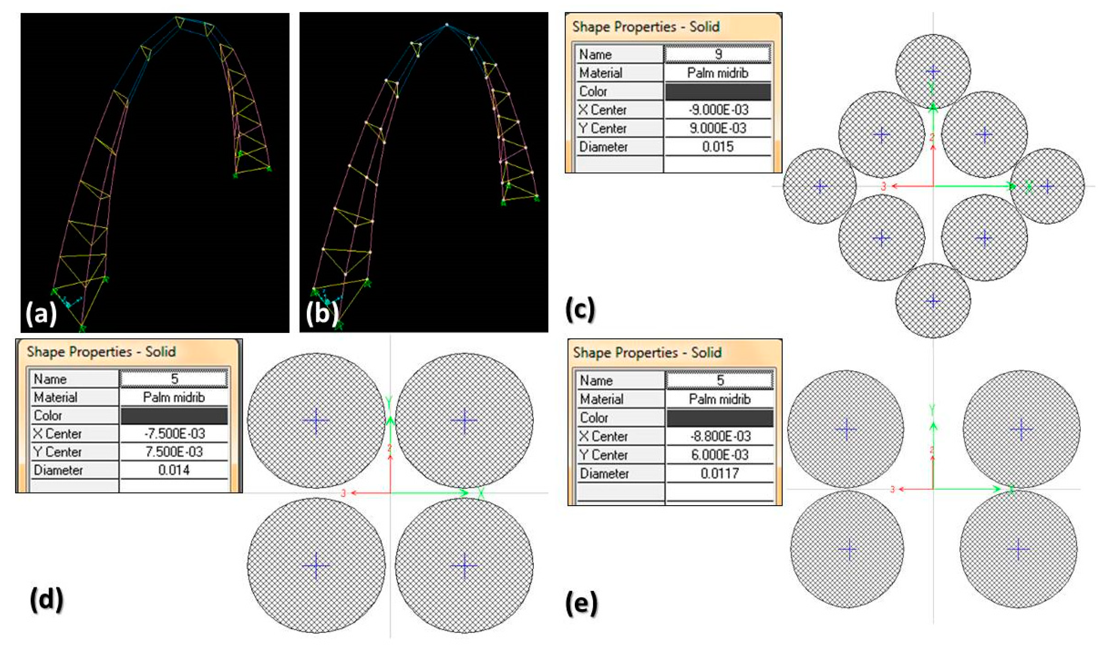
3.2.1. Development of the Finite Element Method (FEM) Model

The finite element method model was analyzed using SAP2000, an integrated software for structural analysis and design by Computers and Structures, Inc., US. A major factor in the accuracy of the digital analysis is the correspondence between the actual specimens and the digital model. Therefore, although the design is originally an arched space truss, the scale of the actual specimens caused that the top bracings to be completely embedded in the thickness of the arched chords. Thus, the bundles of the chords became attached together at the top by the pallet used to take the vertical load, and eventually, the function of the bracings disappeared. Furthermore, the joints in the actual specimens depended only on friction without adhesives. Although the bracings, once inserted in between two chords, could not be moved in or out, they could be rotated by force, which means that the joints had no resistance to moment. Therefore, all joints in the digital model were hinged. The only joints defined to be fixed were the joints at the foundations, where the steel tubes in the prefabricated base in the specimens were completely stuffed that no movement of the chords was allowed at all. Therefore, the design of the digital model was altered to imitate the actual specimen, where the chords were designed to virtually meet at the same joint as shown in Figure 27a,b.
Although the bundles in the specimens were strictly bound and fastened by ropes, the irregular shape of the date palm midrib cross-sections and the cavities left after inserting the bracings made it very important to define well-customized cross-section of the bundles in SAP2000. A solid circular cross-section was defined as the single midrib element in the bracings cross-section. However, predefined solid circular cross-sections would not represent the structural behavior to resemble the real condition of the rope-fastened bundles. Therefore, the cross-sections of the chords were designed using the Section Designer tool in SAP2000. In the bottom bundles, the cross-section was designed to consist of four main midribs and four secondary midribs to represent the overlap area and the additional members below the overlap area. The cross-section of the middle bundle was designed to consist of four midribs. The portion of the middle bundles above the overlap was designed to consist of two groups of midribs to imitate the actual building process, where the middle bundles were divided into two groups before fixing to the bottom bundle. The cross-sections of the bottom, middle bundles and the area above the overlap are shown in Figure 27c–e, respectively.
The mechanical properties of a date palm midrib, as discussed earlier in the Introduction, vary according to the relationship with the direction of the fibers in the midrib, in addition to the type of joinery used in testing in the case of the tensile properties. The chosen mechanical properties, including the orthotropic moduli of elasticity, shear moduli and Poisson ratios, were the properties taken from the compression tests, as the parabolic arched chords were to mainly carry axial compression in normal cases [8,16]. However, from the observation of the structural behavior in the experimental testing, it was noted that the most critical part in the structure was in the middle bundles above the overlap where the failures occurred. The date palm midribs in the middle bundles experienced bending at the overlap area until failure under extreme loading. Therefore, the stresses assigned to the date palm midribs in SAP2000 were gained from the bending tests [3,8,16]. The used mechanical properties are shown in Figure 28.

3.2.2. Validation of the Model

A vertical load was applied at the top of the specimen similar to the experimental program. The load was increased until the failure was reached. After the application of 4 kN vertical load on the top joint (Figure 29a), all middle bundles appeared to be completely flat (Figure 29b). The ultimate analytical deflection was 475 mm (Figure 29c). Failure occurred in the top middle bundles and the portion above the overlap (Figure 29d–f). Recall that the average experimental load was 4.1 kN and the average experimental deflection was 457 mm. The error in the load is negligible and the error in displacement is only 4%. These errors are acceptable for such a simple model and prove the efficiency of the model and the validity of the mechanical properties.

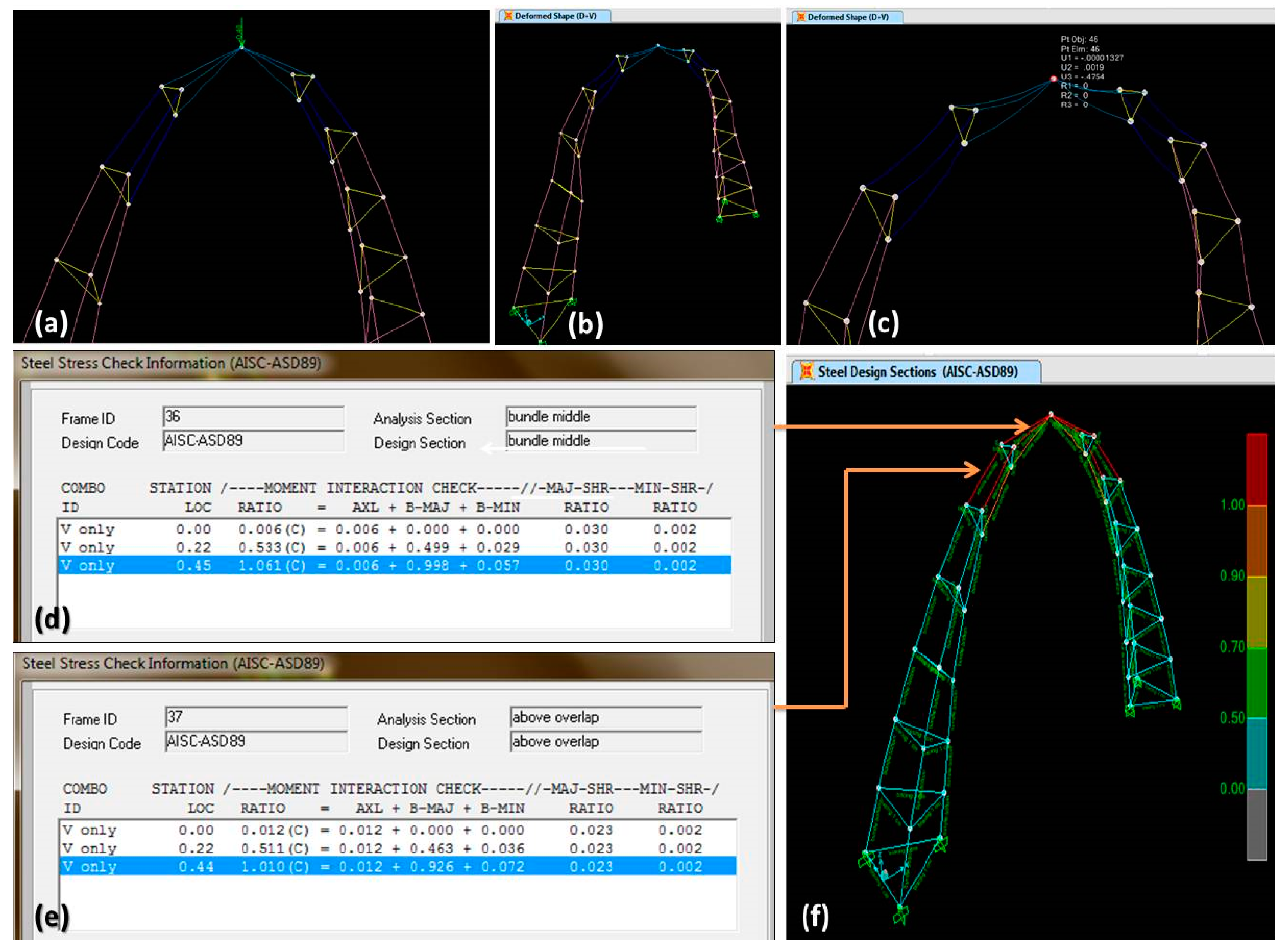
3.3. Analysis of 12 m Span Tri-Arched Space Truss and Discussion

In order to examine the ability of the designed system to cover wide spans, the system with a span of 12 m was analyzed in SAP2000 using the validated mechanical properties. The cross-sections were designed using Section Designer tool in SAP2000 as shown in Figure 30a–c. The initial form is shown in Figure 30d.
The system was tested under extreme wind loads by the Egyptian code and 100 kg/m2 shell loads to imitate the weight of simple wooden sheathing and thatch roofing [25]. The in-plane and out-of-plane wind loads on the system are shown in Figure 31a,b. The shell loads were installed along the higher arches in the system as shown in Figure 31c. The deformations under the in-plane and out of plane wind loads on the system are shown in Figure 31d,e. The design of the cross-sections of the system was safe by a large factor, as shown in Figure 31f. The deformations of the model were small and recoverable.
Thus, the results of the validated 12 m-span model proved that the hypothesis that was generated earlier is valid. The tri-arched space truss system was found to be structurally safe to cover spans of 12 m under own weight, standard roofing and wind loads. The parabolic chords successfully hosted friction joinery that withstood the threat of disassembly while no adhesives were used. This structural performance remained unchanged in the long term specimen, which meant that the creep impact, accumulated during six months, was minimal. Those findings built on the previous studies; by validating the efficiency of the structural concept of the tri-arched space truss, examining the workability of the details of the design and generating a validated model that effectively predicts the structural behavior of date palm midribs under loading. This illustrates the ability of the proposed system to cover wide spans and opens the door for further development.

4. Conclusions

Utilizing date palm midribs in wide-span construction is a promising field of research, as it provides a variety of options for building light and cost-efficient wide-span shaded structures. Reviewing the previous trials of utilizing date palm midribs in wide-span construction showed that the required structural system must ensure containing axial stresses exclusively. This system must also adapt to the microscopic composition, the high flexibility, and the natural shape of the midribs without the need for processing and complicated joinery. Therefore, the tri-arched space truss system was selected for experimenting and analysis. The experimental program of the tri-arched space truss system showed that the system allowed for the high flexibility of date palm midribs, taking the deformation safely until failure that happened gradually and steadily. The long-term specimen showed similar behavior to the short-term specimen, which indicated the possibility of using the system to cover moderate-lived functions. The analytical program showed that the compressive modulus of elasticity and the bending strength of the date palm midribs were mainly responsible for the structural behavior. Those results were used to generate a validated FEM model that proved that the system can cover 12 m safely under its own weight, extreme wind loads and the weight of standard roofing on the system. Such system, if repeated consecutively to create wide-span vaulted spaces, can host a variety of cost-efficient shaded functions for the rural societies in Egypt.
The structural analysis of such wide-span arrangements is recommended based on the validated model that is introduced in this article. Further studies are also recommended to investigate the impact of the outdoor environmental conditions on date palm midribs construction. Accordingly, the types and the impact of fire retardants and the conserving treatments are required to be experimented and analyzed. In addition, further studies are recommended to concentrate on the design of the overlapping area in the date palm midribs bundles chords in order to select the most efficient design, as the failures of the specimens and the FEM models were more concentrated in the overlapping areas. Besides, more extensive research is required to design the foundation of the proposed system. Such research is needed to address issues such as the soil type, interconnection with the date palm midribs bundles, and the details that are required to allow for the transportation of the completed component. Correspondingly, a life cycle analysis (LCA) and a life cost cycle analysis (LCCA) should be investigated and the results compared to conventional light shaded structures in order to determine the fields where the use of the developed date palm midribs tri-arched space truss is most feasible.

Author Contributions

Conceptualization: E.A.D., Y.M. and H.E.; methodology: A.M. and A.A.; software: E.A.D., A.M. and A.A.; validation, E.A.D., A.M. and A.A.; investigation: E.A.D. and H.E.; resources: H.E. and E.A.D.; data curation: E.A.D.; writing—original draft preparation: E.A.D.; writing—review and editing: A.M.; visualization: E.A.D. and A.M.; supervision: Y.M.; project administration: Y.M.; funding acquisition: No external funding was received. All authors have read and agreed to the published version of the manuscript.

Funding

This research received no external funding.

Conflicts of Interest

The authors declare no conflict of interest.

References

  1. El-Mously, H. Innovating green products as a mean to alleviate poverty in Upper Egypt. Ain Shams Eng. J. 2018, 9, 2039–2056. [Google Scholar] [CrossRef]
  2. Elmously, H. Rediscovering Date Palm by-products: An Opportunity for Sustainable Development. In By-Products of Palm Trees and Their Applications; Materials Research Proceedings: Aswan, Egypt, 2019; Volume 11, pp. 3–61. [Google Scholar] [CrossRef] [Green Version]
  3. El-Mously, H. The Industerial Use of the Date Palm Residues: An Eloquent Example of Sustainable Development; United Arab Emirates University: El Ain, United Arab Emirates, 2001; p. 21. Available online: http://citeseerx.ist.psu.edu/viewdoc/download?doi=10.1.1.588.1154&rep=rep1&type=pdf (accessed on 1 April 2020).
  4. Bekheet, S.; Elsharabasy, S.F. Date Palm Status and Perspective in Egypt. In Date Palm Genetic Resources and Utilization; Johnson, D.V., Al-Khayri, J.M., Jain, S.M., Eds.; Springer Science + Business Media: Dordrecht, The Netherlands, 2015; ISBN 978-94-017-9693-4. [Google Scholar]
  5. Wendrich, W.Z. Basketry. In Ancient Egyptian Materials and Technology; Nicholson, P.T., Shaw, I., Eds.; Cambridge University Press: Cambridge, UK, 2009; ISBN 978-0-521-12098-2. [Google Scholar]
  6. Darwish, E.A.; Elmously, H.; Mansour, Y.; Abdelrahman, A. The Technical Heritage of Date Palm Leaves Utilization in Traditional Handicrafts and Architecture in Egypt & the Middle East. In By-Products of Palm Trees and Their Applications; Materials Research Proceedings; Materials Research Forum LLC: Aswan, Egypt, 2019; pp. 325–332. [Google Scholar] [CrossRef] [Green Version]
  7. Darwish, E.A.; Mansour, Y.; Elmously, H.I. Development of the Structural Uses of Date Palm Rachis for Cheap Wide Span Construction for Rural Communities in the Middle East. IOP Conf. Ser. Mater. Sci. Eng. 2018, 371, 012023. [Google Scholar] [CrossRef]
  8. Darwish, E.A.; Mansour, Y.; Elmously, H.; Abdelrahman, A. Development of sustainable building components utilizing date palm midribs for light wide-span multi-purpose structures for rural communities in Egypt. J. Build. Eng. 2019, 24, 100770. [Google Scholar] [CrossRef]
  9. Barreveld, W.H. Date Palm Products; FAO: Rome, Italy, 1993; ISBN 92-5-103251-3. [Google Scholar]
  10. El-Batraoui, M. The Traditional Crafts of Egypt. Amin, G.A., Ed.; The American University in Cairo Press: Cairo, Egypt; New York, NY, USA, 2016; ISBN 978-977-416-753-9. [Google Scholar]
  11. Dabaieh, M. Energy efficient design strategies for contemporary vernacular buildings in Egypt. In Vernacular Heritage and Earthen Architecture; Correia, M., Carlos, G., Rocha, S., Eds.; CRC Press: Boca Raton, FL, USA, 2013; pp. 599–604. ISBN 978-1-138-00083-4. [Google Scholar]
  12. Kennedy, J.F. Building without Borders Sustainable Construction for the Global Village; New Society Publishers: Gabriola Island, BC, Canada, 2008; ISBN 978-0-86571-481-6. [Google Scholar]
  13. Dabaieh, M. Participatory action research as a tool in solving desert vernacular architecture problems in the Western Desert of Egypt. Action Res. 2013, 11, 279–298. [Google Scholar] [CrossRef]
  14. Almusaed, A.; Almssad, A. Building materials in eco-energy houses from Iraq and Iran. Case Stud. Constr. Mater. 2015, 2, 42–54. [Google Scholar] [CrossRef] [Green Version]
  15. Piesik, S. Arish: Palm-Leaf Architecture; Thames & Hudson: London, UK, 2012; ISBN 978-0-500-34280-0. [Google Scholar]
  16. Darwish, E.A.; Mansour, Y.M.; Elmously, H. Date Palm Rachis as a Local and Renewable Structural Material for Rural Communities in Egypt. Int. J. Environ. Sci. Sustain. Dev. 2018, 2, 115–131. [Google Scholar] [CrossRef]
  17. Piesik, S.; Abdelouahhab, Z.; Coleman, J.; Sheehan, P.; Mangelsdorf, W.; Alkhouri, S.; Sunday, P. A Paradigm of Agro-Ecosystems of Date Palm Oases Understood in the Wider Context of Economic and Culture Ecosystems through Transfer of Knowledge and Technology in the Deseret Regions. In Proceedings of the UNCCD 3rd Scientific Conference, Cancun, Mexico, 9–12 March 2015; Available online: https://www.researchgate.net/publication/281773609_A_Paradigm_of_Agro-ecosystems_of_Date_Palm_Oases_Understood_in_the_Wider_Context_of_Economic_and_Culture_Ecosystems_through_Transfer_of_Knowledge_and_Technology_in_the_Deseret_Regions/stats (accessed on 1 April 2020).
  18. El-Shabasy, A.B.; El-Mously, H.I. A study of the variation of the tensile strength across the cross section of date palm leaves’ midrib. In Materials, Functionality & Design, Proceedings of the 5th European Conference on Advanced Materials and Processes and Applications, Maastricht, The Netherlands, 21–23 April 1997; Volume 4: Characterization and production/design; Sarton, L.A.J.L., European Conference on Advanced Materials and Processes and Applications, Federation of European Materials Societies, Nederlands Society for Materials Science, Eds.; Nederlands Society for Materials Science: Zwijndrecht, The Netherlands, 1997; pp. 4/597–4/600. ISBN 978-90-803513-4-9. [Google Scholar]
  19. Mascia, N.T.; Lahr, F.A.R. Remarks on orthotropic elastic models applied to wood. Mater. Res. 2006, 9, 301–310. [Google Scholar] [CrossRef]
  20. El-sherbiny, T.R. Use of Palm Midribs as Structural Elements; Faculty of Engineering, Ain Shams University: Cairo, Egypt, 2010. [Google Scholar]
  21. Macdonald, A. Structure and Architecture, 2nd ed.; Architectural Press: Oxford, UK, 2001; ISBN 978-0-7506-4793-9. [Google Scholar]
  22. Hassan, N.I. Use of Local Raw Materials in Low Cost Roofing; Institute of Environmental Studies & Research, Ain Shams University: Cairo, Egypt, 2001. [Google Scholar]
  23. Ambrose, J.E.; Tripeny, P. Building Structures, 3rd ed.; Wiley: Hoboken, NJ, USA, 2012; ISBN 978-0-470-54260-6. [Google Scholar]
  24. Lan, T.T. Handbook of Structural Engineering, 2nd ed.; Chen, W.-F., Lui, E.M., Eds.; CRC Press: Boca Raton, FL, USA, 2005; ISBN 978-0-8493-1569-5. [Google Scholar]
  25. Neufert, E.; Herz, R. Architects’ Data, 1st English Language ed.; Lockwood: London, UK, 1970; ISBN 978-0-258-96509-2. [Google Scholar]
Figure 1. Examples of the technical heritage of date palm midribs in Egypt. (a) Traditional furniture made from date palm midribs (Fayoum, Egypt). (b) Traditional fruit crate made from date palm midribs (Giza, Egypt). (c) Traditional fencing by date palm midribs (The New Valley, Egypt). (d) Roofing using date palm midribs and date palm trunks (Asuit, Egypt).
Buildings 10 00106 g001
Figure 2. Perspective of arched date palm midribs bundle vault (Reproduced from [15]). (1) Arched date palm midribs bundles. (2) Date palm trunks as intermediate columns. (3) Date palm midribs bundles as purlins.
Buildings 10 00106 g002
Figure 3. Date palm midribs square pyramid space truss (reproduced from [22]). (1) Steel plate. (2) Space truss element made from pressed midribs strips. (3) U-shaped high strength bolts. (4) Steel box connectors.
Buildings 10 00106 g003
Figure 4. Perspective of date palm midribs tri-arched space truss (Reproduced from [8]). (1) The middle midribs bundle is thinner to form the parabolic shape. (2) The bottom midribs bundles are thicker to take thrust. (3) Bracings.
Buildings 10 00106 g004
Figure 5. 1:20 Tri-arched space truss with cantilever sheds made from date palm midribs strips [8].
Buildings 10 00106 g005
Figure 6. Flowchart of the methodology of this article.
Buildings 10 00106 g006
Figure 7. Date palm midribs and the removed leaflets of 3 midribs (Baladi species).
Buildings 10 00106 g007
Figure 8. General dimensions of the specimen.
Buildings 10 00106 g008
Figure 9. The prefabricated base. (a) Top Dimensions of the stainless steel base. (b) Horizontal angle of rotation of the tubes (c) Side view of the base. (d) Vertical angle of inclination of Tube A. (e) Vertical angle of inclination of Tube B. (f)The base after completion.
Buildings 10 00106 g009
Figure 10. The first attempt in building a specimen. (a) Failure in the middle midribs in the first full-length bundle. (b) Bending two bundles together. (c) The first arch after completion. (d) The asymmetrical defect in the completed structure.
Buildings 10 00106 g010
Figure 11. Steps of bending the middle bundle. (1) The first half of the middle bundle, made from 2 midribs, is fixed to the bottom bundle by ropes. (2) The middle bundle is bent by a moving worker. (3) Completing the bending of the middle bundle. (4) Fixing the ending of the middle bundle to the opposing bottom bundle.
Buildings 10 00106 g011
Figure 12. The arches after completion. (a) The specimen after the completion of the arches. (b) Details of the overlap after the addition of the second half of the middle bundle and fixing it to the bottom bundle.
Buildings 10 00106 g012
Figure 13. Installing the bracings. (a) The sharpened ends of the bracings. (b) A worker is opening a space between the midribs in a bundle using a chisel where the second worker is driving the bracing midrib by a wooden hammer. (c) Fastening the bundles with ropes before and after the bracing insertion. (d) The detail of the overlap after fixing additional midribs to increase the cross-section of the bottom bundles.
Buildings 10 00106 g013
Figure 14. The specimens after completion. (a) The first specimen. (b) The second specimen. (c) The third specimen.
Buildings 10 00106 g014
Figure 15. Standard instrumentation of a specimen. (1) Strain gauge No.1. (2) Strain gauge No.2. (3) Strain gauge No.3. (4) Vertical LVDT. (5) Top horizontal LVDT. (6) Bottom horizontal LVDT. (a) Fixation of the strain gauges. (b) Fixation of LVDT.
Buildings 10 00106 g015
Figure 16. Experimentation of the first specimen. (a) Initial state before loading. (b) Reaching the maximum movement by loading jack for the 1st time: 250 mm. (c) Addition of the hydraulic jack after fixing the current height. (d) Specimen at failure.
Buildings 10 00106 g016
Figure 17. Experimentation of the second specimen. (a) Initial state before loading. (b) Reaching the maximum movement by loading jack for the 1st time: 250 mm. (c) Reaching the maximum movement by loading jack for the 2nd time. (d) Specimen at failure.
Buildings 10 00106 g017
Figure 18. Experimentation of the third specimen. (a) Initial state before loading. (b) Reaching the maximum movement by loading jack for the 1st time: 250 mm. (c) Reaching the maximum movement by loading jack for the 2nd time. (d) Specimen at failure.
Buildings 10 00106 g018
Figure 19. The middle of the top of the specimen is pushed below the rest of the flattened area after failure and before releasing the loading jack.
Buildings 10 00106 g019
Figure 20. The form of a specimen after releasing the loads and the completion of testing.
Buildings 10 00106 g020
Figure 21. Failure patterns of date palm midribs. (a) The longitudinal cracks in date palm midribs in tension testing. (b) The breaking failure in date palm midribs in bending testing.
Buildings 10 00106 g021
Figure 22. The failure in the specimens. (a) Longitudinal cracks and breaking failure in the overlapping area in the first specimen. (b) The breaking failure and the longitudinal cracks above and through the overlapping area in the second specimen. (c) The breaking failure and the longitudinal cracks in the third specimen.
Buildings 10 00106 g022
Figure 23. Load versus vertical deformation for the test specimens.
Buildings 10 00106 g023
Figure 24. Horizontal displacement at the bottom LVDT versus vertical deflection.
Buildings 10 00106 g024
Figure 25. Horizontal displacement at the top LVDT versus vertical deflection.
Buildings 10 00106 g025
Figure 26. Strain versus deflection for the three specimens.
Buildings 10 00106 g026
Figure 27. The setup of the digital model of the system in SAP2000. (a) The digital model before updating to match the specimens. (b) The updated digital model. (c) Cross-section of the bottom bundle. (d) Cross-section of the middle bundle. (e) Cross-section of the portion above overlap. (dimensions in m).
Buildings 10 00106 g027
Figure 28. The defined mechanical properties of date palm midribs in SAP2000.
Buildings 10 00106 g028
Figure 29. Digital analysis of the system under own weight and vertical load of 4 kN. (a) Initial shape (b) Deformed shape. (c) Vertical displacement (475 mm). (d) Stress check information of the top middle bundles (ratio = 1.061) (e) Stress check information of the portion above overlap in the middle bundles (ratio = 1.010). (f) Failure is concentrated in the top middle bundles and the portion above the overlap in the middle bundles.
Buildings 10 00106 g029
Figure 30. The setup of the digital model of the system in SAP2000. (a) Cross-section of the bottom bundle. (b) Cross-section of the bracings. (c) Cross-section of the middle bundle. (d) Initial form of the system.
Buildings 10 00106 g030
Figure 31. Digital analysis of the system under own weight, wind loads and shell load of 100 kg/m2. (a) The in-plane wind loads. (b) The out-of-plane wind loads. (c) The applied shell load (d) Deformation resultant from the in-plane wind loads. (e) Deformation resultant from the out-of-plane wind loads. (f) Design is safe.
Buildings 10 00106 g031
Table 1. Estimated amounts of the products of the annual pruning process of Siwi Species (10% moisture content) [3].
Annual QuantitiesPalm MidribsPalm LeafletsSpadix StemsCoirPetioleTotal (Kg/palm)
Dried Kg (per 1 mature female palm) 1514.691.561454.2
Table 2. Mechanical properties of date palm midribs (Baladi species-soft cultivar) according to EN408–2003 (Moisture Content = 10%) [3,8,16,20].
TestProperty DescriptionValue (N/mm2)
TensionLongitudinal Modulus of Elasticity3790
Effective Yield Stress99
Effective Tensile Stress117
CompressionLongitudinal Modulus of Elasticity825
Tangential Modulus of Elasticity 105
Radial Modulus of Elasticity
Effective Yield Stress45
Effective Compressive Stress50
BendingLongitudinal Modulus of Elasticity10,287
Longitudinal-Radial Shear Modulus109
Longitudinal-Tangential Shear Modulus
Effective Yield Stress120
Effective Bending Stress135
CalculatedRadial-Tangential Shear Modulus39.05
Longitudinal-Radial Poisson’s Ratio0.372
Longitudinal-Tangential Poisson’s Ratio 0.467
Radial-Tangential Poisson’s Ratio0.435
Mass per Unit Volume0.95 m/cm3

