
Improving Building Energy Performance Using Dual VAV Configuration Integrated with Dedicated Outdoor Air System


Department of Civil and Architectural Engineering and Construction Management, University of Cincinnati, Cincinnati, OH 45221, USA
*
Author to whom correspondence should be addressed.
Buildings 2021, 11(10), 466; https://doi.org/10.3390/buildings11100466
Submission received: 31 August 2021
/
Revised: 27 September 2021
/
Accepted: 4 October 2021
/
Published: 12 October 2021
(This article belongs to the Section Building Energy, Physics, Environment, and Systems)
Abstract
:As building systems account for almost half of the total energy consumed by the building sector to provide space heating, cooling, and ventilation, efficiently designing these systems can be the key to energy conservation in buildings. Dual VAV systems with an effective control strategy can substantially reduce the energy consumption in buildings, providing a significant scope of further research on this system configuration. This paper proposes to utilize the warm air duct of the dual VAV system as a dedicated outdoor air (DOA) unit when no heating is required, which allows the cooling load to be effectively distributed between two ducts. A specific control sequence is proposed with different supply air temperature reset strategies to estimate the heating, cooling loads, and fan power energy consumption of the proposed system. A simple two-zone office building is taken as a preliminary case study to simulate the airflow rates and fan power of a single duct VAV and proposed dual VAV systems to illustrate the concept. Finally, a larger multi-zone office building is simulated to measure the annual heating, cooling loads, and fan power energy and compare the energy savings among the systems. The results show significant fan power reduction ranging from 1.7 to 9% and notable heating energy reduction up to 76.5% with a small amount of cooling load reduction varying from 0.76 to 2.56% depending on the different locations for the proposed dual VAV systems. Further energy savings from different supply air temperature reset strategies demonstrate the opportunity of employing them according to climates and case studies. The proposed dual VAV system proves to have the potential to be adapted in buildings for the purpose of sustainability and energy savings.
1. Introduction
Buildings in the residential and commercial sectors have accounted for 40% of the total energy consumption in the USA in 2020 [1]. According to the building energy data book of the US Department of Energy, about 50% of the energy consumed by the building sector is directly associated with space heating, cooling, and ventilation [2]. As such, it is crucial to design these systems in a safe and efficient manner while minimizing energy consumption. In the last decade, a significant amount of research has been carried out to achieve better performance and improve the efficiency of such systems [3]. Previously, heating, ventilation, and air conditioning (HVAC) systems were designed to control the temperature with constant air volume (CAV) which did not satisfy the requirements of every zone in a building. Variable air volume (VAV) was later introduced to the systems as a novel solution to control the temperatures in multiple zones [3]. Consequently, Variable air volume (VAV) air conditioning systems have proven to be more economical than other alternatives due to their ability to adjust in response to load variations. Thus, they are being widely adopted in buildings in the USA [4]. As a result, any modification in the design and operation of the VAV systems to reduce building energy consumption will contribute largely to total energy savings in the building sector.
The simplest and most common system-single duct VAV system comprises of one central air handling unit with multiple VAV boxes providing cooling and heating to different zones according to specific needs with one single duct. Thus, the system provides cold air to the zones in cooling loads, and reheat is applied to the cold air to meet the heating demands of other zones. Adding to that, ASHRAE Standard 62 [5] mandates that each zone should have adequate ventilation to dilute accumulated contaminants which should also be supplied by the single duct VAV system with the modulation of outside air damper to bring in fresh air [6]. Since multiple zones have different numbers of occupants, devices, and activities, the ventilation requirement in different terminal units may be unevenly distributed. Due to these two scenarios of simultaneous heating and cooling and various ventilation requirements, there are additional loads to be met on cooling and heating equipment. This makes the single-duct VAV system somewhat ineffective for energy usage reduction. The control strategy suggested in Guideline 36 [7] can be applied to the single duct VAV system to achieve slightly better energy performance in a multi-zone building. However, these strategies can only alleviate the inefficiency to some extent, but it cannot be prevented altogether due to the configuration of the single duct system [8]. Figure 1 shows a simple schematic of the single duct VAV system.
On the contrary, dual duct systems are designed to maintain different temperature setpoints for simultaneous varying loads by mixing two streams of cold and hot supply airflow supplied by two ducts [10]. Primarily, dual duct systems were also constant air volume controls or CAV systems in the 1980s. With time, researches and improvements were made and the CAV system was changed to a VAV system with a single fan or a dual fan configuration [11,12]. Simulations and modeling techniques for optimized performance of the different system components have also been developed [13,14,15,16] along with fault and anomaly detection in system operation [17]. Thus, advanced control strategies and optimization of the dual duct systems can play a significant role in the pursuit of energy consumption reduction and thermal comfort. Suitable applications of the dual duct systems include offices [18], schools [12], multi-purpose commercial spaces [19], etc. In comparison to the dual duct single fan configuration, the dual duct dual fan system uses less energy for air treatment and fan power [20], and ASHRAE guideline 36 [7] has already included the control sequence of dual duct dual fan system where the return air is recirculated by the warm air fan. However, due to the synchronized conditioning and thermal treatment of two airflows, the energy consumption of a dual duct system can be high [10]. Some studies have been performed where a common outdoor air intake is provided for both warm and cold air distribution units [12,21], but this produces high heating loads in winter and the dual fans cannot run in parallel for one specific mode such as cooling when needed.
In response to that, Nassif and Ridwana [9] have proposed a new configuration of dual duct dual fan system referred to as ‘Dual VAV Systems’ where the secondary air distribution system or the warm air distribution system is also equipped with outdoor air intake. The study of this system configuration along with its proposed control sequence has already shown a significant reduction of fan energy and heating load in different climate zones in the USA. There remains a valuable scope of research advancement for this configuration and control strategy development for the purpose of energy conservation. Thus, this paper takes that configuration as a baseline for further study and explores different aspects of energy reduction if these systems are applied in buildings. This research proposes to use the secondary air distribution system to act as a dedicated outdoor air (DOA) unit when in the cooling mode which can bring the required fresh air to the zones in a case study office building. In this way, the primary air distribution system only recirculates and conditions the air without any intake of outdoor air. Consequently, this approach can reduce the fan power of the primary AHU due to lower flow friction while ensuring a healthy breathing zone inside the building with the use of secondary AHU. A new control sequence with two different supply air temperature strategies is also proposed for the operation of this dual VAV configuration integrated with the DOA unit. The control sequence is simulated in the case study building and the energy consumption is compared amongst three cases (single duct VAV, dual VAV, and dual VAV with the DOA system) to measure the energy savings The novelty of the research lies in creatively utilizing the dual VAV system by integrating dedicated outdoor air provision within the configuration along with the new sequence of control to lower the energy consumption of the buildings.
2. Methodology
2.1. Configuration of Dual VAV System and DOA
The new proposed configuration of the dual VAV system is shown in Figure 2. There are two separate air handling units (AHUs) annotated as primary and secondary AHU which consist of both heating and cooling coils. As a result, each AHU has a similar control loop for duct static pressure and supply air temperature (such as a single duct AHU) and can be operated in either cooling or heating mode at any given time. A traditional dual duct dual fan system is not equipped with both heating and cooling coils in a single duct, which explains the name Dual VAV system for this configuration. In addition to that, the zones are equipped with VAV boxes where either one or both dampers can operate to provide the necessary airflow for a certain mode (i.e., heating or cooling, unlike traditional dual duct systems where cold and hot airflow are mixed to maintain the supply temperature). Another major enhancement proposed in the dual VAV system is the provision of outdoor air intake for the secondary AHU. Generally, the primary AHU will provide cold air to the zones in need of cooling and the secondary AHU will operate in heating. However, in Nassif and Ridwana’s work [9], it has been shown that both AHUs can be operated for cooling when needed and secondary AHU can bring necessary ventilation when the primary dampers are closed and vice versa. This control sequence has lowered the load on the equipment leading to a significant reduction in energy consumption.
Therefore, the major focus of the paper is to use the outdoor air intake provision of the secondary AHU as a dedicated outdoor air unit. Dedicated outdoor air (DOA) system refers to a unit assigned to handle the loads from conditioning outside ventilation air where another unit takes care of the rest of the loads generated in a building. Thus, DOA systems condition the outside ventilation air separately from the return air [22]. In a dual VAV system, when there is little or no need for heating and the economizer is also disabled, both primary and secondary AHUs can be used for cooling. In this case, the secondary AHU can operate as a DOA unit, maintaining cold fresh air intake parallel to the primary AHU supply. The primary AHU will only recirculate, cool, and condition the return air which can reduce the fan power for this AHU. For this purpose, the secondary AHU does not need to be equipped with an economizer; the provision to intake outdoor air and control the dampers for minimum air ventilation should suffice. This operational strategy enables the primary AHU to be designed to handle only the effective cooling load instead of the whole cooling load. The effective cooling load is the load after subtracting the ventilation capacity of secondary AHU from the peak cooling load. As both the AHUs, air ducts and VAV boxes will carry the cooling load, the system sizes can be smaller along with reduced fan power and air resistance in each AHU. It is worth mentioning that for the purpose of this study, the secondary AHU is being used as a DOA unit. However, due to the symmetry of the AHUs in the dual VAV configuration, the primary AHU can also be assigned as the DOA unit and the secondary AHU can recirculate the return air in cooling mode.
2.2. Proposed Sequences of Operation
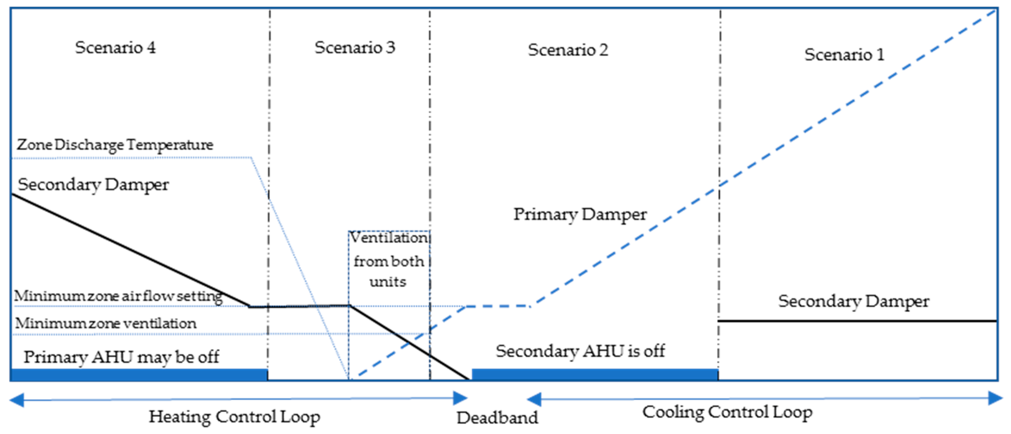
To evaluate the energy consumption for the proposed configuration of a dual VAV system along with a DOA unit, four different scenarios are considered. Table 1 shows the summary of all those scenarios, outdoor air temperature (OAT), the control strategies for both the AHUs and the damper positions. The first scenario is where the outdoor is warm and temperature is above 70 °F (21.1 °C), the economizer is disabled to avoid bringing too much warm air inside and all of the zones are in cooling. The primary AHU is mainly used for the cooling load of the building, and so this AHU is operated in cooling with a supply temperature setpoint of 55 °F (12.8 °C), recirculating the return air without any intake of outdoor air. The primary VAV box damper is modulated to maintain the space temperature through two cascaded control loops. The first loop determines the airflow setpoint, and the second loop modulates the damper position to maintain the actual airflow at that setpoint. However, as there is required minimum ventilation for each zone, the secondary AHU works as a DOA unit for scenario 1 and supplies the minimum outdoor air at the setpoint 55 °F (12.8 °C). The minimum ventilation airflow setpoint generally depends on zone characteristics such as area and occupancy that dynamically vary based on the reading of the occupancy sensor, CO2 sensor, time of day, schedule, etc. Thus, the secondary VAV damper is modulated in similar cascade control loops such as the primary AHU wherein the first loop measures the minimum ventilation airflow for each zone and the second modulates the damper positions to maintain that airflow for ventilation. Table 1 shows the sequence of operation for the proposed dual VAV system with DOA. Here, OAT is outdoor air temperature, SAT is the supply air temperature, OA is outdoor air, and RA is return air.
During mild weather, for example, when the temperature ranges from 55 to 70 °F (12.8 to 21.1 °C), the economizer is enabled. In this range, for scenario 2, most of the zones require cooling and a few zones are either in deadband or in heating due to low cooling loads. The primary AHU operates in a partial or full free cooling mode. The settings for primary dampers are air temperature setpoint for zones in cooling and minimum ventilation requirements for the zones in deadband or heating. The secondary AHU can either be switched on or off. However, if this AHU remains on, it does not introduce any fresh air from outside as the primary AHU is already in economizer mode. The secondary AHU only recirculates the returned air and the dampers are modulated to maintain the temperature setpoint in the zone in heating mode along with reheat if needed. Similar to scenario 2, some zones are in cooling or deadband and others are in heating in scenario 3. The primary AHU remains operational to supply cold air or required ventilation in zones. Thus, primary dampers are controlled to maintain cooling setpoint temperature for the zones in cooling and minimum ventilation for other zones. The secondary AHU is mainly operated to handle the heating load and the temperature of the supply warm air temperature depends on the mixing of the return air and outside air. The dampers are also modulated to provide partial ventilation and minimum airflow for the heating airflow setpoint. The hot water valve becomes operational if the space temperature needs to be maintained after the minimum airflow setpoint. In scenario 4, all of the zones are in heating as the outdoor temperature is cold (below 55 °F or 12.8 °C). As an advantage of the dual VAV system configuration, the primary AHU and dampers are switched off in this case. Only the secondary AHU remains operational to supply warm air along with required ventilation to all the zones. Reheat is also activated when necessary and dampers settings are controlled to maintain space heating temperature setpoint. Figure 3 shows both the AHU and damper control sequence in the four scenarios for the dual VAV system with DOA provision.
2.3. Modeling Strategy
Single duct VAV and dual VAV system configurations are considered in this paper to compare the energy consumption of a dual VAV system with a DOA unit. As both the ducts and air loops in the proposed dual VAV configuration show more similarity to a single duct VAV system, the modeling strategy and comparisons are also based on that instead of a traditional dual duct system. To simulate the single duct and dual VAV systems’ performance, the modeling strategy shown in Figure 4 is developed to simulate the cooling and heating loads on equipment as well as fan power.
The hourly cooling sensible and heating loads are obtained from the energy simulation software eQuest (eQuest v3.65). Based on the sensible loads, the supply air temperature (system-level supply air temperature), and the required zone cooling or heating temperatures, the zone model calculates the zone airflow rates, reheat requirements, and the zone discharge air temperatures by employing the following sensible heat equation:
where q is the sensible load (qs) or reheat (qr), cp is the specific heat of air, m is the mass airflow rate, and Δt is the temperature difference. The zone model is described later in this section. The outside airflow rate is calculated based on the ASHRAE standard 62.1 multi-zone ventilation rate procedure [5]. The loads on cooling and heating coils are determined using the VAV system model, similar to ASHRAE Secondary HVAC toolkit [23] or EnergyPlus [24]. The return air humidity ratio is calculated based on the latent heat equation (a multiplication of latent heat of water evaporation, mass flow rate, and humidity ratio change). The initial supply humidity ratio is assumed. The iteration process is then applied. The mixing air conditions are calculated using energy and mass equations for return and outside of the air stream mixture. The dual-temperature economizer control algorithm is used. The cooling and heating loads are then calculated as a multiplication of the supply mass flow rate, and the mixing air and supply air enthalpy difference. The model strategy includes the simple cooling coil model from ASHRAE Secondary HVAC toolkit [23] or EnergyPlus [24] to estimate the supply humidity ratio.
The system airflow rate vs. and total pressure Pt are the inputs for the fan model. The fan model is similar to the detailed fan model introduced in ASHRAE Secondary HVAC toolkit [22]. The system airflow rate vs. is the sum of zone airflow rates (∑Vz). The total pressure Pt is calculated based on the following equation:
The flow coefficient c is determined from design information (e.g., Pt = 7 in wg, pressure setpoint Pset = 2.5 in wg, and vs. = 2000 cfm for the preliminary example shown below).
The zone model for single-duct VAV systems is shown in Figure 5 and the zone model for dual VAV systems is shown in Figure 6. For a single-duct system, the required zone discharge air temperature Tzd-req to meet zone load is calculated by rearranging Equation (1). The calculation as shown in Figure 5 is based on the minimum zone airflow rate and heating zone temperature. If the calculated discharge air temperature Tzd-req is less than the AHU supply air temperature Ts, the zone will be in cooling or deadband and the zone airflow Vz should be equal to or higher than the minimum airflow value. The zone airflow rate is calculated with the equation as shown in Figure 5. As there is no reheat for this case, the discharge air temperature Tzd should be equal to the supply air temperature. If the calculated discharge air temperature is greater than the supply air temperature, the zone will be in heating and reheat should be activated to raise the supply air temperature from the AHU supply to the required discharge air temperature (equations in Figure 5). If the required air discharge temperature is higher than the maximin limit Tzmax, the temperature should then be set to the maximum limit and the more-than-minimum zone airflow rate should be supplied (equation in Figure 5). Otherwise, the airflow rate should be kept at the minimum limit.
The zone model for dual VAV systems is shown in Figure 6. Similar to the single duct system, the required zone discharge air temperature Tzd-req is calculated. If the required discharge air temperature is less than the supply air temperature, the zone will be in cooling and deadband and the zone airflow rate is calculated by the equation shown in Figure 6. As there is no reheat for this case, the discharge air temperature should be equal to the supply air temperature. If the required discharge air temperature is greater than the supply air temperature, the zone will be in heating, but more importantly, the reheat may not be activated yet. The reheat is activated only if the required discharge air temperature becomes higher than the secondary AHU supply air temperature. This demonstrates why this system would use less heating as compared to the single duct system (compare Figure 5 vs. Figure 6). Also, as the primary zone airflow is zero, no simultaneous heating and cooling occur. If the discharge air temperature is higher than the maximum limit, a higher-than-minimum secondary airflow rate should be then calculated (equation in Figure 6). Otherwise, the airflow rate should be at the minimum limit. When the required discharge air temperature is between the primary and secondary supply air temperatures, the load can be met by mixing the primary and secondary airflow rates. The equations to find those airflow rates are shown in Figure 6.
2.4. Simulation in Two Example Buildings
Two example buildings are taken to simulate the control logic of the proposed system. One simple two-zone 2000 ft2 (185.8 m2) office building is first simulated to calculate loads, airflow rates, and fan power for eight different outdoor temperature conditions in order to illustrate the concept and for discussion. This simulation is simple yet shows effectively how the proposed system can reduce the airflow rates and fan power in the example building. Finally, a multi-zone 25,000 ft2 (2322.6 m2) office building is simulated for the evaluation of total annual cooling, heating loads, and fan power. The comparison is done among single duct, dual VAV, and dual VAV with DOA system to show the energy consumption reduction with different supply air temperature reset strategies. The details of the example buildings and supply air temperature (SAT) reset strategies are discussed in the next section.
3. Description of Case-Study Buildings and SAT Reset Strategies
3.1. Case Study of a Two-Zone Office Building
At first, the two-zone office building is simulated for preliminary calculations. One zone of this example consists of the interior spaces and the other represents exterior spaces; each zone has an area of 1000 ft2 (92.9 m2) and the design cooling load of 22,000 btu/h or 6447.6 W (equivalent to 1 cfm/ft2 based on the space cooling temperature of 75 °F or 21.1 °C and supply air temperature of 55 °F or 12.8 °C). The design airflow rate is 1000 cfm and the minimum airflow rate is 200 cfm which is 20% of the total design flow (0.2 cfm/ft2). The zones are considered as a mix of office and conference spaces with an occupancy of 10. The loads in the exterior zone are assumed to be varied with outdoor air conditions and presented as a percentage of the design load of 22,000 btu/h (6447.6 W). The loads in the interior zone are assumed to be always constant at 80% of the design load (i.e., 17,600 Btu/h or 5158.1 W). A negative load refers to the heating load. The latent loads are assumed to be constant and calculated based on the occupancy in each zone (200 Btu/h per person or 59 W per person). It is also assumed that the primary AHU duct is designed to handle the effective cooling load and the secondary AHU duct is made to be the same size. The design total fan static pressure is assumed to be 7 inWG, the design duct static pressure setpoint is maintained at 2.5 inWG and the fan efficiency is assumed to be constant at 70%.
3.2. SAT Reset Strategies
Different SAT reset strategies are applied for single duct VAV and proposed dual VAV systems to achieve maximum energy savings in different climate zones. For a single-duct VAV system, the SAT reset strategy is based on the outdoor air temperature (OAT) and it is called the OA-SAT reset algorithm. According to this reset algorithm, the SAT is 65 °F (18.3 °C) if the OAT is less than 50 °F (10 °C), the SAT is 55 °F (12.8 °C) if the OAT is greater than 65 °F (18.3 °C), and within the range of 50–65 °F (10–18.3 °C) outside the SAT varies linearly with the OAT. The dual VAV system is considered when the secondary AHU stays off, the economizer is disabled, and when the same OA-SAT reset strategy is applied. Due to the consideration of this specific case, a comparison can be made between the single duct and dual VAV system loads and airflow rates. For a dual VAV system with DOA provision, a case is considered when the secondary AHU operates as DOA to provide required ventilation and the economizer is disabled. A simple SAT reset strategy is used in this case; the primary AHU SAT is kept at a constant of 55 °F (12.8 °C) and the secondary AHU SAT is kept at the highest possible temperature that is obtained from mixing the required OA with return air RA (without using system heating).
3.3. Loads, Airflow Rates, and Fan Power Calculations for the Two-Zone Building Example
Table 2, Table 3 and Table 4 show the results of the loads, airflow rates including outdoor airflow fraction, and fan power for the systems when SAT reset strategies are applied in the case of the two-zone office building. These calculations are done to compare the fan powers of different system configurations with different SAT reset strategies to observe how the proposed system performs in a wide range of outdoor temperatures. The sensible load is presented as a percentage of the total and as the interior zone is always in cooling mode, it is omitted from the tables. The tables are organized in accordance with the outdoor temperature varying from highest to lowest. Here, AHU1 is the primary AHU, AHU2 is the secondary AHU, OA is outdoor air, and SAT is supply air temperature.
Table 2 represents the results of the single duct VAV system. The system flow rate is the sum of two-zone airflow rates and so the interior zone airflow rate can be checked by subtracting the exterior zone airflow rate from the system airflow rate. In Table 2, when the OAT is higher than 70 °F (21.1 °C), the zones are in cooling and the economizer is disabled, the single duct VAV system cools the supply air with the required minimum OA to 55 °F (12.8 °C). For example, in the first case, when the OAT is 95 °F (35 °C), the total supply airflow is 1800 cfm, the exterior zone flow rate is 1000 cfm, the interior zone flow rate is 800 cfm, the corrected OA fraction is 12.4%, the sensible cooling load is 44,515.1 Btu/h (13,046.1 W), the fan power is 1.84 kW, and no reheat is used. In the fourth case when the OAT is 65 °F (18.3 °C) and the economizer becomes enabled, introducing 100% fresh air, the exterior zone is in deadband, the zone airflow rate reaches its minimum airflow rate (200 cfm), no reheat is applied, and fan power is reduced to 0.60 kW. When the OAT is equal to and lower than 60 °F (15.6 °C), the exterior zone switches to operate in heating and the reheat is applied. So, in the fifth case, there is simultaneous heating and cooling in the single VAV system with mechanical cooling of 2126.7 Btu/h (623.3 W) and zone reheat of 806.7 Btu/h (236.4 W). When the OAT is below 55 °F (12.8 °C), the outside air damper is modulated to maintain the supply air temperature at its setpoint. For instance, when the OAT is 45 °F (7.2 °C) and the exterior sensible load is −30%, the OA fraction becomes 38.9%, the discharge temperature reaches the high limit of 90 °F (32.2 °C), so the zone airflow rate increases from minimum airflow rate of 200 cfm to 275 cfm. As the supply air temperature setpoint increases to 65 °F (18.3 °C), the system airflow rate and fan power are increased significantly from previous cases.
Table 3 shows the results for dual VAV systems when the secondary AHU2 stays off and OA-SAT reset algorithm is applied. During warm weather when the OAT is higher than 70 °F (21.1 °C), or the exterior zone is in deadband, both single-duct and dual VAV systems perform similarly as the secondary AHU is not operational. However, in the fifth case, when the OAT is 60 °F (15.6 °C) and OA- SAT reset strategy is applied, the dual VAV systems perform much better than the single duct VAV system. In the dual VAV system, no reheat is used and cooling load is reduced as no simultaneous cooling and heating occur. In the single-duct VAV system, a total of 1160 cfm serving both zones need to be cooled to 58.3 °F (14.6 °C), but in dual VAV systems, only the primary AHU airflow (1146.6 cfm) needs to be cooled. This example only represents two zones, but the reduction can be significant for large-scale systems. For instance, if the total system supply airflow is equally split into the two AHUs, the amount of airflow that needs to be cooled is reduced by 50% from a single duct VAV system. In the cases where both the AHUs are operating, the total fan power of the dual VAV system is also reduced as duct sizes for single VAV and dual VAV systems are kept the same. This fan power reduction is due to reduced flow resistance as both duct systems are used. As economizer remains enabled, the primary AHU introduces a large amount of fresh air and return air recirculated back to the secondary AHU is also rich in the fresh air. Thus, a lower OA fraction is required to be introduced by secondary AHU. For instance, when the OAT is 25 °F or −3.9 °C (last case), the AHU1 OA faction is 18.8% (similar to the one for single duct VAV system), introducing more than the required ventilation, and so the AHU2 OA fraction is reduced to 12.9%.
Table 4 shows the results for dual VAV systems with simple SAT reset when the secondary AHU operates as DOA to provide required ventilation. As the economizer is disabled in this scenario, the primary AHU just circulates and cools the return air. The total system airflow splits into two duct systems, namely the flow resistance and the total fan power are reduced from the previous two systems. Also, as the secondary zone damper maintains the required fresh air in each zone, the system ventilation efficiency (Ev) becomes one (1.0), a lower fraction of fresh air is introduced, and thereby the cooling load is reduced. For instance, at 95 °F (35 °C) OAT, when the AHU2 runs as DOA, the fresh air amount drops from 223.2 cfm (12.4%) to 220 cfm, sensible cooling load drops from 44,515.1 Btu/h to 44,440 Btu/h (13,046.1 to 13,024.1 W). and the fan power reduces from 1.84 kW to 1.49 kW. Again, for large-scale systems serving many zones, when the Ev may be relatively low, the cooling load reduction could be much greater than what is shown in this example. In addition, due to lower SAT, the system airflow rates are decreased for all cases when the OAT is lower than 65 °F (18.3 °C). Compared to single and dual VAV systems with higher SAT setpoint, this provides additional fan energy and required zone reheat reduction. This happens due to the increased fraction of OA in AHU1 and consequently reduced fraction in AHU2 which allows more OA to be circulated back to AHU2. For example, when the OAT is 55 °F (12.8 °C) and the SAT is also 55 °F (12.8 °C) instead of 61.7 °F (16.5 °C) such as the previous systems, the OA fraction for AHU1 increases from 65.9% to 100% and the recirculated air to AHU2 is rich in OA. Consequently, the OA fraction for AHU2 drops from 33.1% to 23.9%, causing the AHU2 supply air temperature to increase from 68.1 °F to 69.8 °F (20.1 to 21 °C) and the zone reheat to drop from 859.6 to 494.2 Btu/h (251.9 to 144.8 W). One important thing to bear in mind for this SAT reset strategy is that keeping SAT at 55 °F (12.8 °C) increases the number of hours the mechanical cooling is used, leading to an increase in the cooling load and cooling energy use. This occurs only when the OAT is between 50–65 °F (10–18.3 °C). This increased energy consumption may or may not exceed the energy savings obtained from the fan. For instance, at OAT of 60 °F (15.6 °C), the cooling load increases from 2043.4 Btu/h to 5103.1 Btu/h (598.9 to 1495.6 W), whereas the fan power drops from 0.74 kW to 0.57 kW. So, during this OAT range (50–65 °F or 10–18.3 °C), there is a trade-off between the cooling load and the fan energy use in dual VAV systems. Otherwise, it is always better to keep the SAT at the lowest possible temperature (55 °F or 12.8 °C) to save fan power and at the same time reduce the heating loads. However, for a single duct VAV system, the scenario is quite complicated as the reheat is added to this trade-off equation. It is not always good to lower SAT to save fan power in this system since that would lead to an increase in both cooling and heating loads. Thus, Table 2, Table 3 and Table 4 show how the supply air temperature, supply airflow, sensible loads, and fan power vary in the single duct and dual VAV systems at different outdoor air conditions. It is observed that using dual VAV systems with DOA provision and SAT reset has resulted in the reduction of the sensible loads and fan power for this building.
3.4. Case Study of a Multi-Zone Office Building
A larger building can show effectively how much energy reduction can be achieved by using the proposed dual VAV system in the above-mentioned SAT reset strategies along with the sequence of control. So, a multi-zone 25,000 ft2 (2322.6 m2) office building is taken as an example to estimate the total annual heating, cooling loads, and fan power. The building has five zones with one large core zone and four exterior zones. Default values are taken for envelope construction, interior details, windows, doors, etc. in different climate zones according to ASHRAE standard 90.1 [25]. The space cooling and supply temperature are kept as 75 °F (23.9 °C) and 55 °F (12.8 °C), respectively, as the previous example. Design airflow rates are determined based on those temperatures and peak cooling loads. The minimum airflow rate is 20% of the total design airflow in this case as well along with the same latent loads for people.
The detailed results of the total annual heating, cooling load, and fan power for the large office building are discussed in the next section. Different locations are considered varying from cold to hot climate zones from the ASHRAE standard 169 [26]. Orlando, Florida, and Phoenix, Arizona are in climate zone 1 that are very hot-humid and very hot-dry locations respectively. Austin, Texas is a hot-humid climate in zone 2. Charlotte, North Carolina, and Los Angeles, California lie in climate zone 3, which are warm locations. Cincinnati, Ohio, and Seattle, Washington are in zone 4 with mixed humid or dry climates. Boston, Massachusetts is in zone 5 having a cool-humid climate. Lastly, Fargo, North Dakota is in zone 7 with a very cold climate. The annual loads are simulated for all the locations mentioned and the percentage of reduction is then compared in the next section.
4. Results and Discussion
4.1. Annual Heating, Cooling Loads and Fan Energy Consumption with OA-SAT Reset Algorithm
To show the energy consumption for annual loads and fan energy uses in a dual VAV system with DOA provision and the proposed sequence of operation, the calculations are conducted for the whole year. The calculations are first carried out for three different cases: (1) single duct VAV system (referred to as SD), (2) dual VAV systems when AHU2 does not operate as DOA (refer to as DD), and (3) dual VAV systems when AHU2 operates as DOA (refer to as DD + DOA). All three cases use the same SAT reset strategy: OA-SAT reset strategy in this comparison. For the dual VAV systems, the OA-SAT algorithm resets the SAT only for AHU1 (the AHU2 SAT is kept as the maximum possible temperature obtained from mixing the required outdoor air and return air). Figure 7, Figure 8 and Figure 9 show the annual heating loads, cooling loads, and fan energy for these three cases.
It is observed that using dual VAV and dual VAV with DOA provision systems reduces a significant amount of heating load in all locations compared to the single duct VAV system. The heating load reduction ranges from 10.3% in Fargo ND for very cold climate, and up to 76.5% in Los Angeles for warm climate when the OA-SAT reset strategy is applied. The DD and DD + DOA produce the same amount of heating load reduction in all locations. It happens since running the AHU2 as a dedicated outdoor air unit in cooling mode will not affect the heating loads of the building. On the contrary, in most locations, using DD does not have a noteworthy reduction of the cooling load, it varies only from 0.53% to 1.01% as shown in Figure 8. However, if AHU2 operates as DOA in cooling (DD + DOA), the annual cooling load is further reduced due to the better system ventilation efficiency (Ev = 1). The maximum cooling load reduction of 2.56% is achieved in Orlando which is a very hot climate as the economizer is frequently disabled and both AHUs run at the same time in cooling. In terms of fan energy, while total system airflow rates are the same for both SD and DD for the same SAT rest strategy, the total flow resistance for DD is lower due to two ducts of the same size than the one for SD. Large fan power reduction is obtained when both AHUs operate in cooling (DD + DOA). For instance, the fan power reductions are 9% and 8.8% for Phoenix and Orlando as both are very hot climates with high cooling loads, as shown in Figure 9. In addition, fan energy reduction is also achieved in a colder climate such as in Fargo or Boston when both primary and secondary AHUs are operating at the same time (one in cooling and the other in heating). The fan energy consumption reductions are 5% and 3.6%, respectively. Overall, it is observed that notable fan energy savings can be achieved by using DD + DOA in cooling mode for hot climate zones.
4.2. Annual Heating and Fan Energy Consumption with Different SAT Reset Strategies
Figure 10, Figure 11 and Figure 12 investigate the energy reduction of dual VAV systems if different types of SAT reset strategies are used. The simple strategy keeps the AHU1 SAT at the lowest possible temperature (e.g., constant at 55 °F or 12.8 °C) and the AHU2 SAT at the maximum possible temperature obtained from mixing the required minimum outdoor air and return air. The dual VAV system with OA-SAT strategy is the baseline for this comparison. The simple strategy is indicated as “constant SAT at 55 °F”. To deal with the increased hours of mechanical cooling due to the simple SAT reset strategy discussed previously, the SAT can be reset within this OAT range of 50–65 °F (10–18.3 °C) not to be constant at the lowest. This modified strategy is indicated as “SAT reset” in Figure 10, Figure 11 and Figure 12.
As shown in Figure 10, it is observed that annual heating loads remain similar for both the simple strategy and SAT reset within the range of 50–65 °F (10–18.3 °C). However, contrary to the case in the single duct VAV system, keeping the AHU1 SAT at 55 °F (12.8 °C) for the dual VAV system has achieved a significant reduction of heating loads from OA-SAT reset strategy varying from 1.95 to 30.94% in different climate locations. In addition, the simple SAT reset also leads to a substantial fan energy saving due to the reduced AHU1 airflow rate required to meet the cooling loads. The saving varies with the location. For instance, the fan energy saving could be up to 23.41% in Cincinnati, a mixed climate zone. This is due to the increase in the AHU1 OA fraction due to which more unused OA can be recirculated back into the AHU2, leading to the reduction in the required AHU2 OA fraction. Also, it should be noted that the zone reheat is applied only when the primary cold air damper is completely closed (Figure 3), so the AHU1 SAT temperature will not have any impact on the amount of zone reheats needed.
One drawback of keeping SAT at 55 °F (12.8 °C) compared to OA-SAT is the increase of cooling loads due to the increase in the number of hours the mechanical cooling is used instead of economizer/free cooling within the range of OAT at 50–65 °F (10–18.3 °C) and there is a tradeoff between the fan and cooling energy uses. As seen in Figure 11 and Figure 12, a lower SAT increases cooling energy use but reduces fan energy consumption. For example, in Figure 11 and Figure 12, the cooling load for Orlando increases by 0.58% but fan energy decreases by 3.05% from OA-SAT reset strategy due to keeping always constant SAT at 55 °F (12.8 °C). The “SAT reset” where the SAT is not constant within the range of OAT at 50–65 °F (10–18.3 °C) can be implemented if the objective is to reduce cooling loads. Comparing to the OA-SAT strategy, this modified reset strategy keeps the same cooling loads and still reduces heating load and fan energy consumption but not as much as the simple strategy (. As shown in Figure 10 and Figure 12, the heating reduction is 17.69% and fan reduction is 1.95% for Orlando when the “SAT reset” is used as compared to 19.73% and 3.05%, respectively, for simple strategy-constant SAT at 55 °F (12.8 °C).
5. Conclusions
As the importance of energy conservation has grown in recent years, innovation and enhancement have become necessary for our conventional building systems. The configuration of dual VAV systems has proven to be beneficial for energy use reduction with a specific sequence of operations. This study shows the innovation of control strategy and sequence of operation on the same system configuration to achieve better and efficient energy performance. The proposed dual VAV system with DOA provision prevents the simultaneous cooling and heating scenario while maximizing the use of outdoor air for cooling, taking advantage of both air handling systems for distributing cooling loads and effectively recirculating air for heating loads. A simple two-zone office building was taken as a preliminary case study and the calculation for single duct VAV and proposed dual VAV systems have shown how supply air temperature varies and fan power reduces due to the effective use of dual VAV systems with outdoor temperatures. The case study of a large multi-zone office building was then simulated for total annual energy consumption and shows noteworthy energy savings in different climates by using the proposed control sequence. By comparing the single-duct VAV with the dual VAV system when the secondary AHU operates as DOA in cooling and when both systems use the same reset control strategy (OA-SAT strategy), the heating load reductions vary from 10.3% to 76.5%, the cooling reductions vary from 0.76% to 2.56%, and the fan annual energy use savings vary from 1.7 to 9% depending on different locations. Furthermore, additional fan energy savings and heating load reductions are obtained when the recommended simple SAT is applied to keep the supply constant at 55 °F or 12.8 °C. The heating reductions vary from 1.96% to 33.27% and the fan savings vary 3% to 29.58% for different locations compared to OA-SAT reset strategy. Keeping the SAT constant with the dual VAV system has proven to be beneficial for mixed and cold climates as well by reducing a larger percentage of fan power.
Comparing the results of energy reduction from a single duct VAV system, the dual VAV system shows huge potential to be used in large-scale multi-zone buildings. Although the amount of energy saving varies for DOA provision and SAT reset, the dual VAV system shows lower energy consumption for most of the climate zones. There remains the further possibility of research on employing this configuration, proposed sequence of operation, and simulated results to reduce the sizing and costs of the HVAC components and equipment. The energy benefits and savings may even exceed the initial cost associated with the dual VAV configuration. However, those remain outside the scope of this study. The integrated approach utilizing the configuration of a dual VAV system with DOA provision along with the proposed control sequence aims to initiate innovative changes to our building systems to achieve the greater purpose of energy efficiency and sustainability in the future.
Author Contributions
Conceptualization, N.N. and I.R.; methodology, N.N. and I.R.; software, N.N. and I.R.; validation, N.N.; formal analysis, N.N. and I.R.; investigation, N.N. and I.R.; data curation, N.N. and I.R.; writing—original draft preparation, N.N. and I.R.; writing—review and editing, I.R.; visualization, N.N. and I.R.; supervision, N.N.; project administration, N.N. Both authors have read and agreed to the published version of the manuscript.
Funding
This research received no external funding.
Institutional Review Board Statement
Not applicable.
Informed Consent Statement
Not applicable.
Data Availability Statement
The data presented in this study are available on request from the corresponding author.
Conflicts of Interest
The authors declare no conflict of interest.
References
- Monthly Energy Review, EIA-US Energy Information Administration. May 2021. Available online: https://www.eia.gov/totalenergy/data/monthly/ (accessed on 16 June 2021).
- Maasoumy, M.; Sangiovanni-Vincentelli, A. Smart Connected Buildings Design Automation: Foundations and Trends. Found. Trends Electron. Des. Autom. 2016, 10, 1–143. [Google Scholar] [CrossRef] [Green Version]
- Rismanchi, B.; Zambrano, J.M.; Saxby, B.; Tuck, R.; Stenning, M. Control strategies in multi-zone air conditioning systems. Energies 2019, 12, 347. [Google Scholar] [CrossRef] [Green Version]
- Qin, J.; Wang, S. A fault detection and diagnosis strategy of VAV air-conditioning systems for improved energy and control performances. Energy Build. 2005, 37, 1035–1048. [Google Scholar] [CrossRef]
- ASHRAE. ASHRAE Standard 62.1-Ventilation for Acceptable Indoor Air Quality; American Society of Heating, Refrigerating, and Air-Conditioning Engineers, Inc.: Atlanta, GA, USA, 2019. [Google Scholar]
- Stanke, D. The Threefold Challenge of Ventilating Single-Duct VAV Systems. Trane Eng. Newsl. 1998, 27, 8. [Google Scholar]
- ASHRAE. ASHRAE Guideline 36-High-Performance Sequences of Operation for HVAC Systems; American Society of Heating, Refrigerating, and Air-Conditioning Engineers, Inc.: Atlanta, GA, USA, 2018. [Google Scholar]
- Nassif, N. Using Dual-Duct, Dual-VAV to Reduce Cooling & Heating Loads. ASHRAE J. 2020, 62, 14–21. [Google Scholar]
- Nassif, N.; Ridwana, I. New Configuration and Control for Dual VAV Systems to Achieve Better Building Energy Efficiency, Accepted. In Proceedings of the ASHRAE Winter Conference, Las Vegas, NV, USA, 29 January–2 February 2022. [Google Scholar]
- Przydróżny, E.; Przydróżna, A. Energy-efficient hybrid dual-duct dual-fan systems. Rev. Romana Ing. Civ. 2019, 10, 266–271. [Google Scholar]
- Wei, G.; Martinez, J.; Minihan, T.; Brundidge, T.; Claridge, D.E.; Turner, W.D. Improving Control of a Dual-Duct Single-Fan Variable Air Volume Systems. In Proceedings of the Third International Conference for Enhanced Building Operations, Berkeley, CA, USA, 13–15 October 2003. [Google Scholar]
- Warden, D. Dual fan, dual duct goes to school. ASHRAE J. 2004, 46, 18. [Google Scholar]
- Talib, R.; Nabil, N.; Choi, W. Optimization-based data-enabled modeling technique for HVAC systems components. Buildings 2020, 10, 163. [Google Scholar] [CrossRef]
- Salsbury, T.; Diamond, R. Performance validation and energy analysis of HVAC systems using simulation. Energy Build. 2000, 32, 5–17. [Google Scholar] [CrossRef]
- Ridwana, I.; Nassif, N.; Choi, W. Modeling of Building Energy Consumption by Integrating Regression Analysis and Artificial Neural Network with Data Classification. Buildings 2020, 10, 198. [Google Scholar] [CrossRef]
- Tahmasebi, M.; Nassif, N.; Eaton, K.; Talib, R. Smart Integrated Optimization Technique for Large Chilled Water Systems. ASHRAE Trans. 2019, 125, 83–86. [Google Scholar]
- Zhou, X. Experimental study of lab-controlled faults in dual-duct VAV system. ASHRAE Trans. 2015, 121, 1VV. [Google Scholar]
- Sotura, M. Dual-fan system. ASHRAE J. 2011, 53, 54–58. [Google Scholar]
- Schuler, M. Dual fan, dual-duct system meets air quality, energy-efficiency needs. Fuel Energy Abstr. 1996, 6, 460. [Google Scholar]
- Warden, D. Dual fan, dual duct systems: Better performance at a lower cost. ASHRAE J. 1996, 38, 36–41. [Google Scholar]
- Przydróżny, E.; Przydróżna, A.; Szczęśniak, S. Energy efficient setting of supply air temperature in dual-duct dual-fan ventilation systems with extract air recirculation. Therm. Sci. Eng. Prog. 2018, 5, 69–85. [Google Scholar] [CrossRef]
- Dieckmann, J.; Roth, K.W.; Brodrick, J. Dedicated outdoor air systems. ASHRAE J. 2003, 45, 58. Available online: https://uc.idm.oclc.org/login?qurl=https%3A%2F%2Fwww.proquest.com%2Fscholarly-journals%2Fdedicated-outdoor-air-systems%2Fdocview%2F220451662%2Fse-2%3Faccountid%3D2909 (accessed on 7 July 2021).
- Brandemuehl, M.J.; Gabel, S.; Andresen, I. HVAC 2 Toolkit: Algorithms and Subroutines for Secondary HVAC System Energy Calculations; American Society of Heating, Refrigerating and Air-Conditioning Engineers: Atlanta, GA, USA, 1993. [Google Scholar]
- Energy Plus. EnergyPlus™ Documentation, Engineering Reference, Version 9.0.1. Available online: https://www.osti.gov//servlets/purl/1395882 (accessed on 9 October 2018).
- ASHRAE. ASHRAE Standard 90.1-Energy Standard for Buildings Except Low-Rise Residential Buildings; American Society of Heating, Refrigerating, and Air-Conditioning Engineers, Inc.: Atlanta, GA, USA, 2019. [Google Scholar]
- ASHRAE. ASHRAE Standard 169-Climatic Data for Building Design Standards; American Society of Heating, Refrigerating, and Air-Conditioning Engineers, Inc.: Atlanta, GA, USA, 2020. [Google Scholar]
Figure 1.
Schematic of single VAV system configuration [9].
Figure 1.
Schematic of single VAV system configuration [9].

Figure 2.
Proposed dual VAV system configuration [9].
Figure 2.
Proposed dual VAV system configuration [9].

Figure 3.
AHU and damper control sequence for proposed dual VAV system with DOA provision.

Figure 4.
Modeling strategy used for single-duct and dual VAV systems.

Figure 5.
Zone modeling strategy used for single duct VAV boxes.

Figure 6.
Zone modeling strategy used for dual VAV boxes.

Figure 7.
Annual heating loads for three cases and reduction by using the proposed system.

Figure 8.
Annual cooling loads for three cases and reduction by using the proposed system.

Figure 9.
Annual fan energy use for three cases and reduction by using the proposed system.

Figure 10.
Annual heating loads for dual VAV systems using different SAT reset strategies.

Figure 11.
Annual cooling loads for dual VAV systems using different SAT reset strategies.

Figure 12.
Annual fan energy for dual VAV systems using different SAT reset strategies.


Table 1.
The sequence of operation for dual VAV system and DOA.
| Scenario Description | AHU and Damper Positions | |||||
|---|---|---|---|---|---|---|
| No | Mode of Operation | OAT Temperature | Primary AHU | Primary Damper | Secondary AHU | Secondary Damper |
| 1 | All zones in cooling, | OAT > 70 °F (21.1 °C) | ‘On’, only recirculating return air | ‘Modulated’ to meet zone temperature setpoint (cooling) | ‘On’ as DOA in cooling | “Modulated” to provide the required ventilation |
| 2 | Most zones in cooling, a few in deadband or heating | OAT ranges from 55 °F to 70 °F (12.8 to 21.1 °C) [Economizer enabled/disabled] | “On” with 100% OA (Economizer) in partial or full free cooling | “Modulated” to provide cooling or maintain the minimum ventilation for the zones in heating or deadband | “On or Off”. If on, it only recirculates the return air | “Modulated” to supply minimum airflow to maintain the heating setpoint. “Closed” for cooling mode |
| 3 | Some zones in cooling or deadband, others in heating | OAT around 55 °F (12.8 °C) | “On” with the lowest possible SAT (e.g., 55 °F or 12.8 °C) | “Modulated”, similar to Scenario 2 | “On” with the maximum SAT obtained from mixing RA and OA. Heating may be applied if the obtained SAT is less than 65 °F (18.3 °C) | “Modulated” similar to Scenario 2. The hot water valve becomes operational after the minimum airflow setpoint |
| 4 | All zones in heating | OAT < 55 °F (12.8 °C), cold outside | “Off” | “Closed” | “On” like Scenario 3 | “Modulated” to supply warm air and required ventilation |
Table 2.
Calculations for Single Duct VAV system.
| OA | Exterior Zone | System Airflow | OA Fraction | SAT | Sensible Loads | Fan | |||||||
|---|---|---|---|---|---|---|---|---|---|---|---|---|---|
| OA | Load | Airflow | Reheat | AHU1 | AHU1 | AHU1 | Cooling | Reheat | Power | ||||
| Temp | % | CFM | btu/h | CFM | % | °F | btu/h | btu/h | kW | ||||
| 95.0 | 100% | 1000.0 | - | 1800.0 | 12.4 | 55.0 | 44,515.1 | - | 1.84 | ||||
| 85.0 | 60% | 600.0 | - | 1400.0 | 16.1 | 55.0 | 33,285.1 | - | 1.10 | ||||
| 75.0 | 30% | 300.0 | - | 1100.0 | 24.0 | 55.0 | 24,200.0 | - | 0.71 | ||||
| 65.0 | 20% | 200.0 | - | 1000.0 | 100.0 | 55.0 | 11,000.0 | - | 0.60 | ||||
| 60.0 | 10% | 200.0 | 806.7 | 1160.0 | 100.0 | 58.3 | 2126.7 | 806.7 | 0.77 | ||||
| 55.0 | 0% | 200.0 | 2273.3 | 1400.0 | 65.9 | 61.7 | - | 2273.3 | 1.10 | ||||
| 45.0 | −30% | 275.0 | 8140.0 | 1875.0 | 38.9 | 65.0 | - | 8140.0 | 2.01 | ||||
| 25.0 | −60% | 550.0 | 14,740.0 | 2150.0 | 18.8 | 65.0 | - | 14,740.0 | 2.75 | ||||
Table 3.
Calculations for Dual VAV system.
| OA | Exterior Zone | System Airflow | OA Fraction | SAT | Sensible Loads | Fan | |||||||
|---|---|---|---|---|---|---|---|---|---|---|---|---|---|
| OA | Load | Airflow1 | Airflow2 | Reheat | AHU1 | AHU2 | AHU1 | AHU2 | AHU1 | AHU2 | Cooling | Heating | Power |
| Temp | % | CFM | CFM | btu/h | CFM | CFM | % | % | °F | °F | btu/h | btu/h | kW |
| 95.0 | 100% | 780.0 | 220.0 | - | 1800.0 | - | 12.4 | - | 55.0 | 55.0 | 44,515.1 | - | 1.84 |
| 85.0 | 60% | 380.0 | 220.0 | - | 1400.0 | - | 16.1 | - | 55.0 | 55.0 | 33,285.1 | - | 1.10 |
| 75.0 | 30% | 80.0 | 220.0 | - | 1100.0 | - | 24.0 | - | 55.0 | 55.0 | 24,200.0 | - | 0.71 |
| 65.0 | 20% | 200.0 | - | - | 1000.0 | - | 100.0 | - | 55.0 | 55.0 | 11,000.0 | - | 0.60 |
| 60.0 | 10% | 154.6 | 45.4 | - | 1114.6 | 45.4 | 100.0 | - | 58.3 | 74.5 | 2043.4 | - | 0.74 |
| 55.0 | 0% | - | 200.0 | 859.6 | 1200.0 | 200.0 | 65.9 | 33.1 | 61.7 | 68.1 | - | 859.6 | 0.91 |
| 45.0 | −30% | - | 275.0 | 7311.4 | 1600.0 | 275.0 | 38.9 | 23.6 | 65.0 | 68.8 | - | 7311.4 | 1.55 |
| 25.0 | −60% | - | 550.0 | 14,109.1 | 1600.0 | 550.0 | 18.8 | 12.9 | 65.0 | 67.9 | - | 14,109.1 | 1.69 |
Table 4.
Calculations for Dual VAV system with DOA provision and simple SAT reset strategy.
| OA | Exterior Zone | System Airflow | OA Fraction | SAT | Sensible Loads | Fan | |||||||
|---|---|---|---|---|---|---|---|---|---|---|---|---|---|
| OA | Load | Airflow1 | irflow2 | Reheat | AHU1 | AHU2 | AHU1 | AHU2 | AHU1 | AHU2 | Cooling | Heating | Power |
| Temp | % | CFM | CFM | btu/h | CFM | CFM | % | % | °F | °F | btu/h | btu/h | kW |
| 95.0 | 100% | 780.0 | 220.0 | - | 1580.0 | 220.0 | - | 100.0 | 55.0 | 55.0 | 44,440.0 | - | 1.49 |
| 85.0 | 60% | 380.0 | 220.0 | - | 1180.0 | 220.0 | - | 100.0 | 55.0 | 55.0 | 33,220.0 | - | 0.89 |
| 75.0 | 30% | 80.0 | 220.0 | - | 880.0 | 220.0 | - | 100.0 | 55.0 | 55.0 | 24,200.0 | - | 0.59 |
| 65.0 | 20% | 200.0 | - | - | 1000.0 | - | 100.0 | - | 55.0 | 55.0 | 11,000.0 | - | 0.60 |
| 60.0 | 10% | 127.8 | 72.2 | - | 927.8 | 72.2 | 100.0 | - | 55.0 | 74.4 | 5103.1 | - | 0.57 |
| 55.0 | 0% | - | 200.0 | 494.2 | 800.0 | 200.0 | 100.0 | 23.9 | 55.0 | 69.8 | - | 494.2 | 0.51 |
| 45.0 | −30% | - | 275.0 | 6679.3 | 800.0 | 275.0 | 79.4 | 10.7 | 55.0 | 71.6 | - | 6679.3 | 0.55 |
| 25.0 | −60% | - | 550.0 | 13,696.2 | 800.0 | 550.0 | 38.5 | 8.3 | 55.0 | 69.7 | - | 13,696.2 | 0.69 |
Publisher’s Note: MDPI stays neutral with regard to jurisdictional claims in published maps and institutional affiliations. |
© 2021 by the authors. Licensee MDPI, Basel, Switzerland. This article is an open access article distributed under the terms and conditions of the Creative Commons Attribution (CC BY) license (https://creativecommons.org/licenses/by/4.0/).
Share and Cite
MDPI and ACS Style
Nassif, N.; Ridwana, I. Improving Building Energy Performance Using Dual VAV Configuration Integrated with Dedicated Outdoor Air System. Buildings 2021, 11, 466. https://doi.org/10.3390/buildings11100466
AMA Style
Nassif N, Ridwana I. Improving Building Energy Performance Using Dual VAV Configuration Integrated with Dedicated Outdoor Air System. Buildings. 2021; 11(10):466. https://doi.org/10.3390/buildings11100466
Chicago/Turabian StyleNassif, Nabil, and Iffat Ridwana. 2021. "Improving Building Energy Performance Using Dual VAV Configuration Integrated with Dedicated Outdoor Air System" Buildings 11, no. 10: 466. https://doi.org/10.3390/buildings11100466
Note that from the first issue of 2016, this journal uses article numbers instead of page numbers. See further details here.