
Assessment of Rotational Stiffness for Metallic Hinged Base Plates under Axial Loads and Moments
by

Mahmoud T. Nawar
1, 
Ehab B. Matar
1,
Hassan M. Maaly
1,
Ahmed G. Alaaser
1 and
Ayman El-Zohairy
2,*
1
Structural Engineering Department, Zagazig University, Zagazig 44519, Egypt
2
Department of Engineering and Technology, Texas A&M University-Commerce, Commerce, TX 75429, USA
*
Author to whom correspondence should be addressed.
Buildings 2021, 11(8), 368; https://doi.org/10.3390/buildings11080368
Submission received: 29 June 2021
/
Revised: 5 August 2021
/
Accepted: 17 August 2021
/
Published: 19 August 2021
(This article belongs to the Special Issue Development of Connections in Steel Structures for Construction)
Abstract
:Pinned base plate connections are the most common base connection used in low-rise steel buildings. In this research, an extensive parametric study is performed using the Finite Element (FE) software Abaqus to determine the elastic rotational stiffness, moment resistance, and energy absorption of the pinned base plate connection connected to a reinforced concrete footing and subjected to an eccentric axial load. The developed FE model is validated using experimental results from the literature. Moreover, an intensive parametric study is conducted to understand the behavior of these connections better. The investigated parameters include the base plate thickness, anchor bolt diameter, and arrangement and number of bolts. The most effective parameters that affect the elastic rotational stiffness and moment resistance of pinned base connections are the anchor bolt arrangement and diameter. The maximum increase in the rotational stiffness was 53% for the anchor bolt diameter of 30 mm when the base plate thickness increased from 12 mm to 30 mm. Based on the base plate thickness, the moment resistance is improved by 150–260% when the bolt diameter increases from 12 mm to 30 mm.
1. Introduction
Low- and medium-rise steel structures are widely used all over the world as industrial buildings, stores, schools, markets, and warehouses. These types of buildings are commonly used because of their low cost and quick fabrication and construction. Reactions of columns (moment, shear, and axial forces) are transferred to foundations through their bases, which can be pinned, semi-rigid, or fixed connections. The moment distribution, as well as lateral drifts in columns, are changed according to the shape of the base plate connection. For low-rise buildings, pinned base plate connections (see Figure 1) with assumptions of no moment are commonly used because of the smaller values of the lateral drifts. Moreover, the required foundation sections for these connections are smaller. On the other hand, using semi-rigid base plate connections as pinned connections by neglecting their rotational stiffness leads to larger lateral drifts than the actual values. Therefore, the semi-rigid base plate connections should be defined with the actual rotational stiffness. Moreover, the pinned connections act as semi-rigid connections and can transfer part of the applied moment to foundations by exhibiting rotational stiffness resistance. During design, the rotational stiffness of the pinned and semi-rigid base plate connections is ignored in single-story low-rise buildings [1]. The prediction of this rotational stiffness is more complicated due to various factors such as the bond between the anchor bolts and concrete base, the stress concentration on concrete under the compression flanges of columns, and the behavior of the grout bed under the steel base plate.
Excessive previous studies explored behaviors of the steel base plate connections and the complex relationships among their components. Experimental studies were conducted on steel base plate connections to investigate the effect of the base plate thickness, anchor diameter, and load eccentricity on the monotonic and cyclic moment capacities and rotational stiffness of these connections [2,3,4,5,6]. Most of these studies were performed on anchor bolts outside the steel column flanges [4,5,6]. Yielding or rupture of the base plate and anchor bolt were the main modes of failure, which were followed by weld cracking and concrete crushing. Relatively limited experimental studies were conducted to study the column base plate connections with anchor bolts inside the steel column flanges [7,8,9,10]. Full-scale steel frames supported by base plate connections with rods inside the column flanges were tested by [11,12,13]. Considering moment restrains for the pinned base connections led to reductions in the service deflections and strength requirements [14,15]. Moreover, reductions in the structure weight up to 12% were obtained [1]. These studies confirmed that the main parameters, which affect the rotational stiffness, were the compressive axial force, anchor bolt diameter, bolt distribution, and base plate thickness: the greater the axial compressive force, the greater the rotational stiffness [1,16,17].
Eurocode 3 [18] grossly overestimated the rotational stiffness of the pinned base plate connections. Moreover, the improved formula by [19] could not predict all cases of these connections. Therefore, an intensive parametric study is presented in this study to understand the behavior of these pinned base plate connections better and calculate their rotational stiffness accurately. A Finite Element (FE) model was developed and validated using experimental results from the literature. Moreover, an intensive parametric study is conducted to understand the behavior of these connections better. The investigated parameters include the base plate thickness, anchor bolt diameter, and arrangement and number of bolts.
2. Finite Element Simulation
A FE model was developed using the numerical software Abaqus, 2017 [20], to simulate a cantilever steel column with a steel base plate connection tested by Gomez et al. [21].
2.1. Geometry of Columns
The steel column section was W200 × 213 (W8 × 48 of A992 Grade 55). The cross-section of the column was constant through the total height with a web of 400 mm × 12 mm and two equal flanges of 200 mm × 16 mm each. The column height was 1000 mm and welded to a base plate of 432 mm × 250 mm. The steel base plate was connected to a reinforced concrete base with four anchor bolts of 19 mm diameter. The steel column flanges were embedded in the reinforced concrete base with an end washer plate. Table 1 shows the values of ultimate and yield stresses which are used in the FE analysis. Moreover, Table 2 lists the concrete and grout material characterizations that are used for the validations.
2.2. Selection of Elements
The eight-node fully integrated brick element, C3D8, was used to model the components under the effect of bending. These components include the base plate, anchor bolts, washers, and nuts. The loading plate, grout, and reinforced concrete base were mainly under the effect of bearing stress. Therefore, the solid element C3D8R with reduced integration was used to model these components. The steel column was represented with general-purpose four-node shell elements, C4R, with reduced integration. This element is suitable to model each of the two flanges and web of the column if local buckling is not required [20]. Two nodes truss element, T3D2, with linear displacement was used to simulate the steel reinforcement bars embedded in the concrete base. The steel column, loading plate, and base plate were simulated as one unit with different material properties for each part because they are welded together. Moreover, the reinforced concrete base and grout were simulated as one unite because of the strong bond between them [21,22]. Figure 2 shows an illustration of the FE model as one-half of the connection with a plane of symmetry passing through the column web thickness. Each of the anchor bolts, including the nuts and square washers, was modeled as one part. The square washers and nuts are simulated as thick square plates, as shown in Figure 3.
2.3. Meshing and Convergence Study
The mesh size was chosen according to the mesh sensitivity study to achieve accuracy of the numerical and computation time. Moreover, each part of the FE model was meshed separately with different sizes according to the sensitivity and importance of this part. The mesh size of the steel column, loading plate, and base plate was 10 mm. The mesh size was refined around the holes, in the anchor bolt cross-section, and through the base plate thickness. The anchor bolt mesh size was 10 mm along the length. The mesh size of the reinforced concrete base was 35 mm.
2.4. Component Interaction and Contact
The three main components of the connection (steel column, reinforced concrete base, and anchor bolt) were assembled by defining the contact surface properties between them. The contact between the steel base plate and grout is “hard contact” with the allowance of separation [20]. The coefficient of friction was 0.45, as mentioned by [21]. Another contact surface was defined between the anchor bolt washer and base plate (steel-steel contact) as hard contact with the allowance of separate property, and the coefficient of friction was 0.8 [23]. The contact between the anchor bolt and the reinforced concrete base includes two parts. The first part is between the outer circular surfaces of the anchors and concrete, which is a frictionless surface [17]. The second one is between the anchor bolt end washer and concrete, which is simulated as hard contact with the allowance of separation.
2.5. Material Definition
All steel parts were modeled as non-linear isotropic hardening material with stress–strain curves provided by [21] under the effect of monotonic loading. The modulus of elasticity of steel was 2.0 × 10⁵ MPa with a Poisson ratio of 0.3. Each steel part (anchor bolt, steel column, base plate, and loading plate) has a different stress–strain curve, which was adopted in the FE model, as provided by Gomez et al. [21]. The concrete damage plasticity model was defined for grout and concrete [20]. The failure stresses were defined by [21], and the stress–strain curve for concrete was modeled as in [24]. The nuts, washers, and loading plate were modeled as rigid and elastic materials. The reinforcement steel bars are defined as bi-linear elastic perfectly plastic material with a yield stress of 400 MPa. For models under the effect of cyclic loading, kinematic hardening plasticity is defined for each material.
2.6. Boundary Condition and Loading Protocol
The lateral monotonic load was applied at the top of the steel column as a lateral deformation in the FE model. The modeled lateral deformation value is reported in the validation section. Moreover, the cyclic loading protocol was used to validate the FE model. The steel column with welded base plate was supported to the reinforced concrete base using a set of anchor bolts. The lower surface of the reinforced concrete base was fully restrained from rotation and transition. Moreover, the symmetrical plane was defined for the FE model at the centerline of the steel column web.
2.7. Validation of the FE Model
Two validations were conducted for two specimens with the same dimensions and materials but under the effect of two different loading protocols, monotonic and cyclic loading, tested by Gomez et al. [21].
2.7.1. The First Specimen under Monotonic Loading
This specimen was subjected to lateral deformation of 250 cm in one direction and zero axial load. Figure 4 shows a good agreement between the experimental and FE results. However, the FE model does not reach the ultimate load because of the stress failure in the anchor bolts. The modes of failure of the tested specimen and FE model are illustrated in Figure 5. The great similarity of deformation is shown by taking into consideration the difference between the ultimate loads for each case. Moreover, the vertical deformation contours of the base plate are almost the same for the FE model and tested specimen (see Figure 6).
2.7.2. The Second Specimen under Cyclic Loading
This specimen was tested under the effect of cyclic loading following the cycle curve protocol, as shown in Figure 7a [21]. The material kinematic hardening model was defined for the plates, anchor bolts, and anchor bolt with one plate washer at the top. The contact between the washer plate and base plate allows separation to take into consideration the effect of the washer plate under the base plate during the reversible loading. Figure 7b shows a good agreement between the FE and experimental results in terms of the base moment and column drift.
3. Parametric Study
An extensive parametric study was performed using the validated FE model to provide perfect descriptions and determine the elastic rotational stiffness, moment resistance, and energy absorption of the base plate connections. The parametric study investigated four variables for each specimen: the number of bolts (B), the diameter of anchor bolts (D), the distance between the anchor bolt and the center line of the base plate (S), and the base plate thickness (T). The steel column in each specimen was supported by a reinforced concrete base and under the effect of an eccentric compressive axial load. This effect was represented by axial concentric compressive and lateral loads. Each specimen was labeled with a unique name to cover all studied parameters, i.e., specimen (B4-D18-S050-T24) can be defined as follows: the number 4 in B4 refers to the number of anchor bolts, where the number of anchor bolts varies from two to six, as shown in Figure 8; the number 18 in D18 refers to the anchor bolt diameter in mm, where the anchor bolt diameter varies from 12 mm to 30 mm; the number 050 in S050 refers to the spacing between the anchor bolt and the center line of the base plate (see Figure 8c,d), where the spacing varies from 0 to 150 mm to represent 0%, 25%, 50%, and 75% of half of the steel column depth; the number 24 in T24 refers to the abase plate thickness in mm, which varies from 12 mm to 30 mm.
According to the AISC limit state [25], the service drift limit for medium-height steel frames should not exceed the height of the column “H” divided by 150 (H/150). The drift of the column through the loading process can be represented through the rotation of column “θ” by dividing the lateral drift over the column height (see Figure 9a). The value of drift at the top of the column was 6.67 mm, which represents 0.67% of the column height. Moreover, the applied moment at this limitation (H/150) was calculated from the FE analysis (see Figure 9b). The rotational stiffness at H/150 was calculated by dividing the applied moment by the rotation “θ” (see Figure 9b). The energy absorption at this value of drift was calculated as the area under the M-θ Curve (see Figure 9c). The calculated values are listed in Table 3 for the analyzed specimens.
Figure 10, Figure 11 and Figure 12 show the moment rotation curves, deformed shapes, and von misses stresses at the drift level of H/150 for analyzed specimens with different bolt numbers and arrangements. The base plate thickness and bolt diameter were kept constant for comparison purposes. The maximum rotation was selected to be 0.02 rad. because the current study aims to explore the rotational stiffness at the elastic region. For the same number of bolts, the rotational stiffness increased by 6.67% when the spacing between bolts increased from 100 mm to 300 mm (see Figure 11a and Figure 12a). Moreover, an incredible improvement in the rotational stiffness was obtained when the number of bolts increased from four to six at the same spacing (31% increase). These results confirm that the bolt arrangement plays a vital role in controlling the rotational stiffness of the base plate connections.
3.1. Effect of the Base Plate Thickness (T)
The base plate thicknesses of 12, 18, 24, and 30 mm are investigated in this section. The base plate thickness shows a slight effect on the moment resistance and rotational stiffness of the pinned base plate connection when using smaller bolt diameters (12 mm and 18 mm). The anchor bolts with smaller diameters control the behavior and subsequently trivialize the effect of the base plate thickness. On the other hand, 24–53% enhancements in the moment resistance are obtained when the base plate thickness increases with using bigger bolt diameters (24 mm and 30 mm). For using bigger bolt diameters, the base plate thickness controls the behavior. However, these improvements vanish at the thickness of 30 mm (see Figure 13). This trend of results is observed for all other arrangements and diameters of the anchor bolts in the base plate connections.
3.2. Effect of the Anchor Bolt Diameter (D)
The anchor bolt diameters of 12, 18, 24, and 30 mm are investigated in this section. The results shown in Figure 14 conclude that the anchor bolt diameter increases the moment resistance of the pinned base plate connections. Moreover, this improvement in the moment resistance is enhanced as the base plate thickness increases. At the base plate thickness of 12 mm, the moment resistance is improved by 150% when the bolt diameter increases from 12 mm to 30 mm (see Figure 14a). However, 260% improvement is obtained when using the base plate thickness of 30 mm (see Figure 14d). Moreover, the increase in the elastic moment resistance reaches 284% for specimens with a base plate thickness of 30 mm and spacing of 150 mm. Therefore, the anchor bolt diameter plays the main role of increasing the moment resistance.
3.3. Effect of the Anchor Bolts Arrangement (Number and Spacing)
The anchor bolt numbers two, four, and six with different spacing are investigated in this section. Figure 15 displays the moment–rotation curves for specimens with different anchor bolt diameters and arrangements, but the base plate thickness is constant (18 mm). Figure 15a shows an increase in the elastic rotational stiffness by 50% for the four bolts arrangement, and the spacing increases from 50 mm to 150 mm. However, a 37% increase is obtained for the six bolts arrangement and the spacing increases from 100 mm to 150 mm. In the same context, the six-bolt arrangement increases the elastic rotational stiffness by 44% when S increased from 100 mm to 150 mm, and the anchor bolt diameter is 18 mm. The distance between the anchor bolts has a greater effect on the rotational stiffness and moment capacity in the elastic region than the number of bolts. Moreover, this effect increases as the bolt diameter increases. Although the values of the rotational stiffness are equal at the drift limit of H/150, the specimens provide different behavior before that limit. Therefore, the comparison is constructed based on the values of K2, which are listed in Table 3.
4. Discussions of the FE Results
To investigate the rotational behavior of the pinned base connection, the elastic rotational stiffness, moment resistance, and energy absorption are calculated and listed in Table 3 for each analyzed specimen at the drift level of H/150 [19]. The tension force in each of the anchor bolts is also listed in Table 3. Figure 16 shows the anchor bolt arrangement according to the direction of the applied moment.
The inelastic behaviors of the specimens were investigated by creating four piecewise linear best fit to the moment–rotation envelopes [16], as shown in Figure 17. The piecewise linear response fitting of specimens B2-D12-S000-T12 and B6-D24-S150-T30 are shown in Figure 18. In the first branch, the stiffness K1 is determined by the elastic rotational stiffness. However, the best fit that minimizes the error between the idealized curve and the envelope obtained from the FE results is used to determine the parameters K2 (see Figure 17).
Figure 19 shows the tensile stresses on the anchor bolts during loading. The tensile stresses in the anchor bolts at the tension side of the moment have a similar trend for different anchor bolt diameters, the same arrangements of bolts, and the same base plate thickness (see Figure 19a). On the other hand, the anchor bolts at the compression side experience small tensile stresses when the anchor bolt diameters increase in size (see Figure 19b).
Figure 20 shows the tensile stresses in the anchor bolts for four and six bolts arrangements. The trend of the tensile stresses is similar between the two specimens. However, the middle anchor in the specimen with six bolts arrangement supports more stiffness, and the elastic moment resistance increases by 32%.
Figure 21 illustrates the effect of the anchor bolt diameter and base plate thickness on the rotational stiffness. The maximum increase in the rotational stiffness was 53% for the anchor bolt diameter of 30 mm when the base plate thickness increased from 12 mm to 30 mm (see Figure 21e). Moreover, the increasing rate drops whenever the anchor bolt diameter decreased. This phenomenon applies to any diameter of the anchors and different thicknesses of the base plate. Figure 21b–d show that the increase in the spacing between the anchors leads to reductions in the effect of the base plate thickness (case of four bolts arrangement). The column flange supports the base plate against bending when the anchors move closer to the column flanges.
Because of the flopped results for specimens with different distances between the anchor bolts at the drift level of H/150, the values of K2 from Table 3 are used as the rotational stiffness in Figure 22. These results confirm the significant effects of the diameter and arrangement of the anchor bolts on the rotational stiffness values. Increasing the number of bolts and spacing leads to enhancements in the rotational stiffness. Moreover, this improvement in the rotational stiffness increases as the bolt diameter becomes bigger (see Figure 22).
5. Conclusions
In this research, an extensive parametric study on pinned base connections is mainly presented to determine the elastic rotational stiffness and moment resistance of these connections at the design serviceability limits. The main findings are summarized as follow:
- The most effective parameters that affect the elastic rotational stiffness and moment resistance of pinned base connections are the anchor bolt arrangement and diameter. The base plate thickness has a slight effect;
- The maximum increase in the rotational stiffness was 53% for the anchor bolt diameter of 30 mm when the base plate thickness increased from 12 mm to 30 mm;
- Based on the base plate thickness, the moment resistance improved by 150–260% when the bolt diameter increased from 12 mm to 30 mm;
- An increase in the elastic rotational stiffness by 50% was obtained for the four bolts arrangement, and the spacing increased from 50 mm to 150 mm. However, only a 37% increase was obtained for the six bolts arrangement, and the spacing increased from 100 mm to 150 mm;
- Increasing spacing between the anchor bolts leads to reductions in the effect of the base plate thickness on the rotational stiffness.
Author Contributions
Supervision, validation, formal analysis: M.T.N.; visualization, writing original draft: E.B.M. and H.M.M.; investigation, resources, software: A.G.A.; supervision, data curation, writing—review and editing: A.E.-Z. All authors have read and agreed to the published version of the manuscript.
Funding
This research received no external funding.
Conflicts of Interest
The authors declare no conflict of interest.
References
- Kavoura, F.; Gencturk, B.; Dawood, M.; Gurbuz, M. Influence of base-plate connection stiffness on the design of low-rise metal buildings. J. Constr. Steel Res. 2015, 115, 169–178. [Google Scholar] [CrossRef]
- DeWolf, J.T.; Sarisley, E.F. Column Base Plates with Axial Loads and Moments. J. Struct. Div. 1980, 106, 2167–2184. [Google Scholar] [CrossRef]
- Burda, J.J.; Itani, A.M. Studies of Seismic Behavior of Steel Base Plates; 1999; Available online: http://hdl.handle.net/11714/7252 (accessed on 1 May 1999).
- Thambiratnam, D.; Paramasivam, P. Base Plates under Axial Loads and Moments. J. Struct. Eng. 1986, 112, 1166–1181. [Google Scholar] [CrossRef]
- Stamatopoulos, G.; Ermopoulos, J.C. Experimental and analytical investigation of steel column bases. J. Constr. Steel Res. 2011, 67, 1341–1357. [Google Scholar] [CrossRef]
- You, Y.-C.; Lee, D. Development of improved exposed column-base plate strong-axis joints of low-rise steel buildings. J. Constr. Steel Res. 2020, 169, 106062. [Google Scholar] [CrossRef]
- Picard, A.; Beaulieu, D. Behaviour of a simple column base connection. Can. J. Civ. Eng. 1985, 12, 126–136. [Google Scholar] [CrossRef]
- Lim, W.-Y.; Lee, D.; You, Y.-C. Exposed column-base plate strong-axis connections for small-size steel construction. J. Constr. Steel Res. 2017, 137, 286–296. [Google Scholar] [CrossRef]
- Picard, A.; Beaulieu, D.; Pérusse, B. Rotational restraint of a simple column base connection. Can. J. Civ. Eng. 1987, 14, 49–57. [Google Scholar] [CrossRef]
- Liu, T.C.-H. Investigation of rotational characteristics of column ‘PINNED’ bases of steel portal frames. Steel Compos. Struct. 2001, 1, 187–200. [Google Scholar] [CrossRef]
- Bajwa, S. Assessment of Analytical Procedures for Designing Metal Buildings for Wind Drift Serviceability; 2010; p. 204. Available online: http://hdl.handle.net/10919/34623 (accessed on 3 August 2010).
- Hong, J.K.; Uang, C.M. Cyclic Performance Evaluation of a Metal Building System with Web-Tapered Members; Report No. SSRP-06/23; Department of Structural Engineering, University of California: La Jolla, CA, USA, 2006. [Google Scholar]
- Kim, S.-E.; Lee, D.-H.; Ngo-Huu, C. Shaking table tests of a two-story unbraced steel frame. J. Constr. Steel Res. 2006, 63, 412–421. [Google Scholar] [CrossRef]
- Eröz, M.; White, D.W.; Desroches, R. Direct Analysis and Design of Steel Frames Accounting for Partially Restrained Column Base Conditions. J. Struct. Eng. 2008, 134, 1508–1517. [Google Scholar] [CrossRef]
- Watwood, V.B. Gable Frame Design Considerations. J. Struct. Eng. 1985, 111, 1543–1558. [Google Scholar] [CrossRef]
- Kavoura, F.; Gencturk, B.; Dawood, M. Reversed Cyclic Behavior of Column-to-Foundation Connections in Low-Rise Metal Buildings. J. Struct. Eng. 2017, 143, 04017095. [Google Scholar] [CrossRef]
- Kanvinde, A.; Jordan, S.; Cooke, R. Exposed column base plate connections in moment frames—Simulations and behavioral insights. J. Constr. Steel Res. 2013, 84, 82–93. [Google Scholar] [CrossRef]
- Da Silva, L.S.; Simões, R.; Gervásio, H. Design of Steel Structures: Eurocode 3: Design of Steel Structures, Part 1-1: General Rules and Rules for Buildings; John Wiley & Sons: Hoboken, NJ, USA, 2012. [Google Scholar]
- Kavoura, F.; Gencturk, B.; Dawood, M. Evaluation of existing provisions for design of “pinned” column base-plate connections. J. Constr. Steel Res. 2018, 148, 233–250. [Google Scholar] [CrossRef]
- Abaqus, Computer Software for Finite Element Analysis, Dassault Systems Simulia; Dassault Systèmes Simulia Corp: Providence, RI, USA, 2016.
- Gomez, I.; Deierlein, G.; Kanvinde, A. Exposed Column Base Connections Subjected to Axial Compression and Flexure; 2010; Available online: https://datacenterhub.org/resources/1239 (accessed on 28 August 2010).
- Astaneh, A.; Bergsma, G.; Shen, J.H. Behavior and design of base plates for gravity, wind and seismic loads. In Proceedings of the National Steel Construction Conference, Chicago, IL, USA, 3–5 June 1992; pp. 209–214. [Google Scholar]
- Igor, S.; Grigoriev, E. Handbook of Physical Quantities, 1st ed.; Available online: https://www.routledge.com/Handbook-of-Physical-Quantities/Grigoriev-Meilikhov-Radzig/p/book/9780849328619 (accessed on 22 May 2021).
- FIB Bulletin 65: Model Code 2010—Final Draft, Volume 1; FIB—The International Federation for Structural Concrete: Lausanne, Switzerland, 2012.
- AISC. Steel Construction Manual, 14th ed.; AISC: Chicago, IL, USA, 2010. [Google Scholar]
Figure 1.
The traditional shape of pinned base connection.

Figure 2.
Finite Element Model.

Figure 3.
Simulation of the anchor bolt with washer and nut: (a) FE model and (b) experimental test.
Figure 3.
Simulation of the anchor bolt with washer and nut: (a) FE model and (b) experimental test.

Figure 4.
Moment–deformation relationships of the tested specimen and FE model.
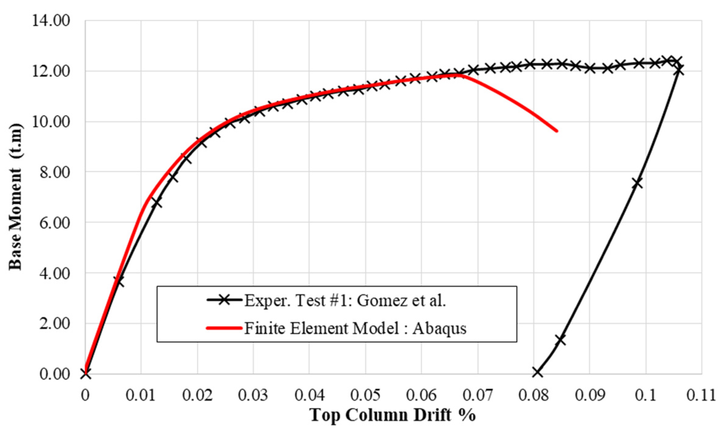
Figure 5.
Modes of failure of the base plate: (a) FE model and (b) experimental test.

Figure 6.
Vertical deformation contours of the base plate: (a) FE model and (b) experimental test.
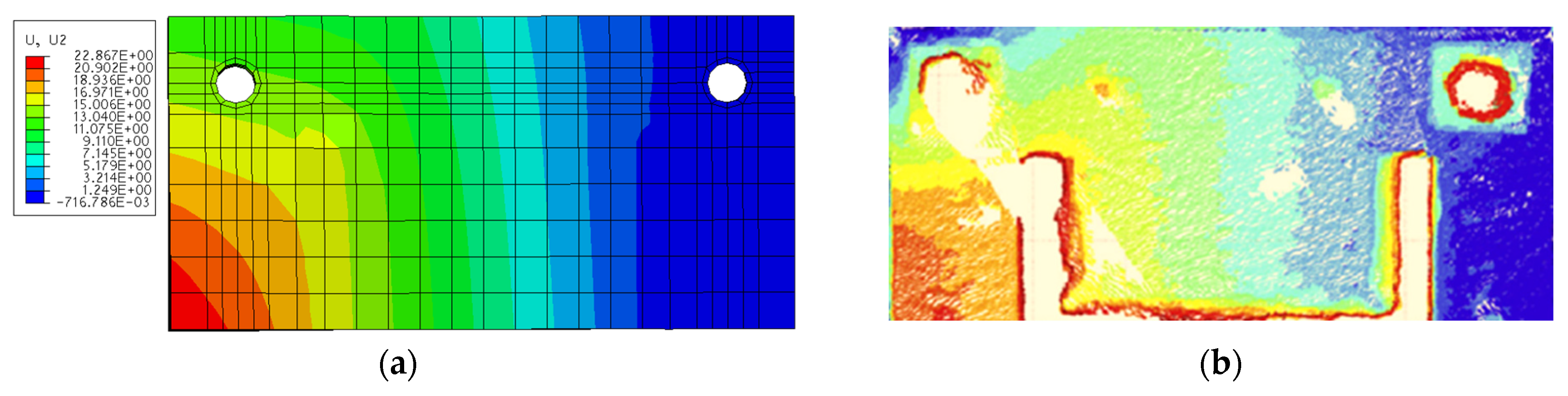
Figure 7.
Validation of the second specimen: (a) cyclic loading protocol and (b) base moment vs. column drift for the FE and experimental results.
Figure 7.
Validation of the second specimen: (a) cyclic loading protocol and (b) base moment vs. column drift for the FE and experimental results.
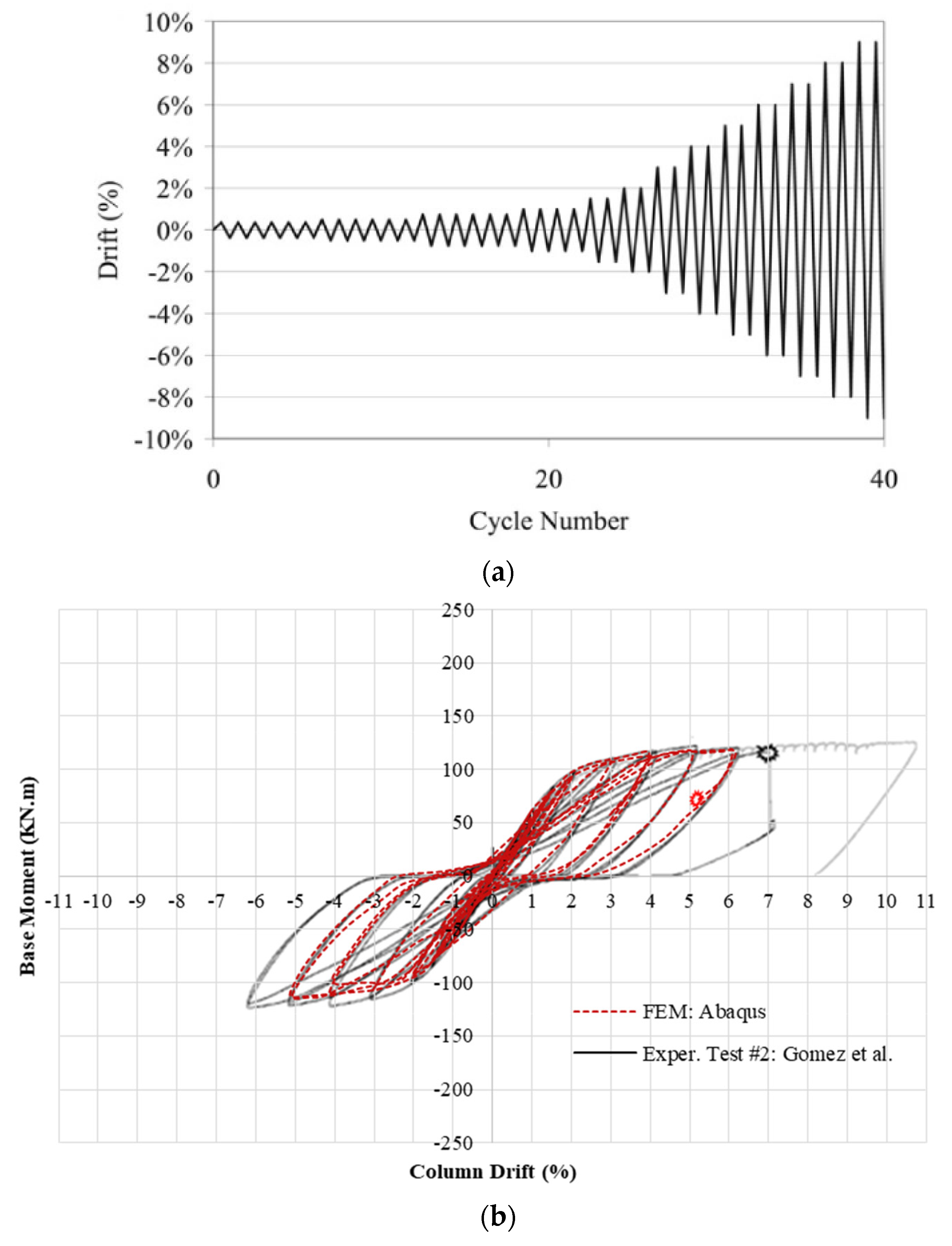
Figure 8.
Various arrangements of the base plate connection: (a) sectional elevation, (b) plan of two anchors, (c) plan of four anchors, and (d) plan of six anchors.
Figure 8.
Various arrangements of the base plate connection: (a) sectional elevation, (b) plan of two anchors, (c) plan of four anchors, and (d) plan of six anchors.
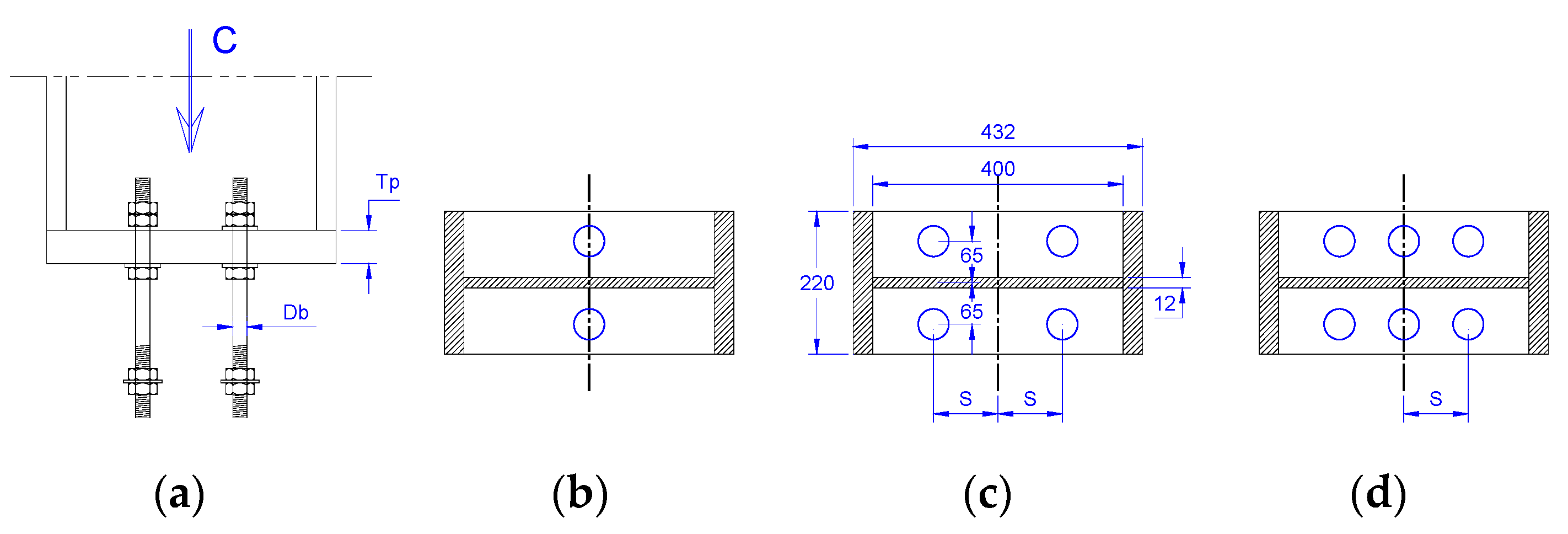
Figure 9.
Schematic for calculating the (a) rotation θ = δ/H, (b) rotational stiffness K = M/θ, and (c) moment and energy at certain value of rotation.
Figure 9.
Schematic for calculating the (a) rotation θ = δ/H, (b) rotational stiffness K = M/θ, and (c) moment and energy at certain value of rotation.

Figure 10.
Specimen B2-D18-S000-T18: (a) moment–rotation curve, (b) deformed shape–von misses stress at H/150 column drift.
Figure 10.
Specimen B2-D18-S000-T18: (a) moment–rotation curve, (b) deformed shape–von misses stress at H/150 column drift.

Figure 11.
Specimen B4-D18-S050-T18: (a) moment–rotation curve, (b) deformed shape–von misses stress at H/150 column drift.
Figure 11.
Specimen B4-D18-S050-T18: (a) moment–rotation curve, (b) deformed shape–von misses stress at H/150 column drift.
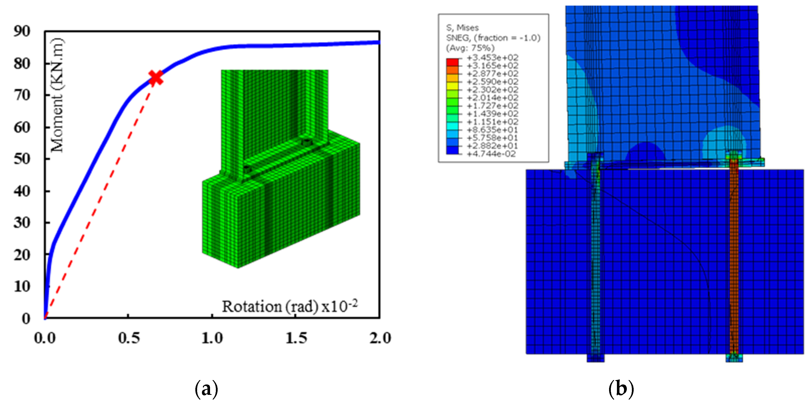
Figure 12.
Specimen B6-D18-S150-T18: (a) moment–rotation curve, (b) deformed shape–von misses stress at H/150 column drift.
Figure 12.
Specimen B6-D18-S150-T18: (a) moment–rotation curve, (b) deformed shape–von misses stress at H/150 column drift.

Figure 13.
Effect of the base plate thickness (T) on the rotational stiffness for different anchor bolt diameters (D): (a) D = 12 mm, (b) D = 18 mm, (c) D = 24 mm, and (d) D = 30 mm (four anchor bolts and S = 50 mm).
Figure 13.
Effect of the base plate thickness (T) on the rotational stiffness for different anchor bolt diameters (D): (a) D = 12 mm, (b) D = 18 mm, (c) D = 24 mm, and (d) D = 30 mm (four anchor bolts and S = 50 mm).
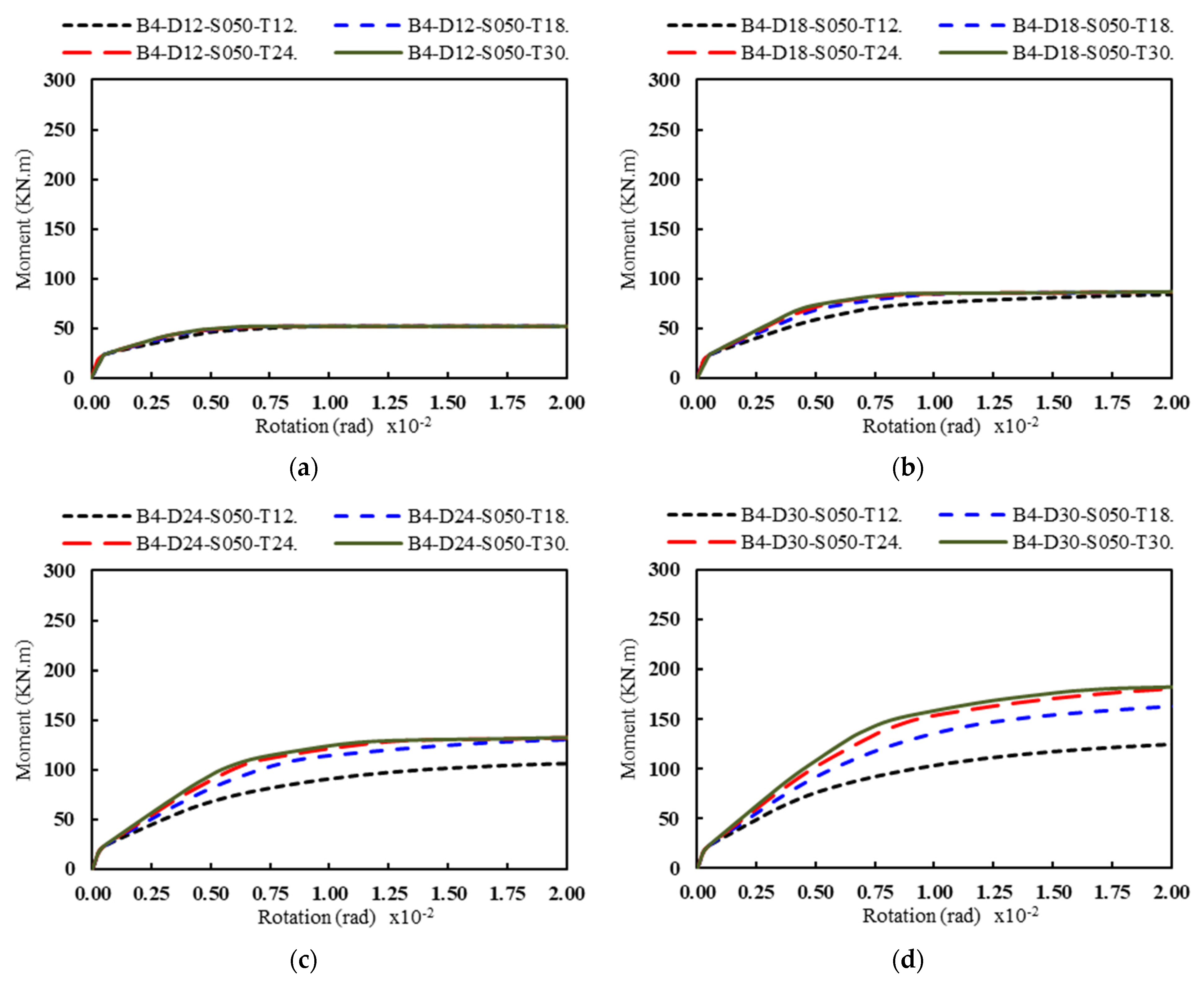
Figure 14.
Effect of the anchor bolt diameter (D) on rotational stiffness for different base plate thickness (T): (a) T = 12 mm, (b) T = 18 mm, (c) T = 24 mm, and (d) T = 30 mm (Four anchor bolts and S = 50 mm).
Figure 14.
Effect of the anchor bolt diameter (D) on rotational stiffness for different base plate thickness (T): (a) T = 12 mm, (b) T = 18 mm, (c) T = 24 mm, and (d) T = 30 mm (Four anchor bolts and S = 50 mm).
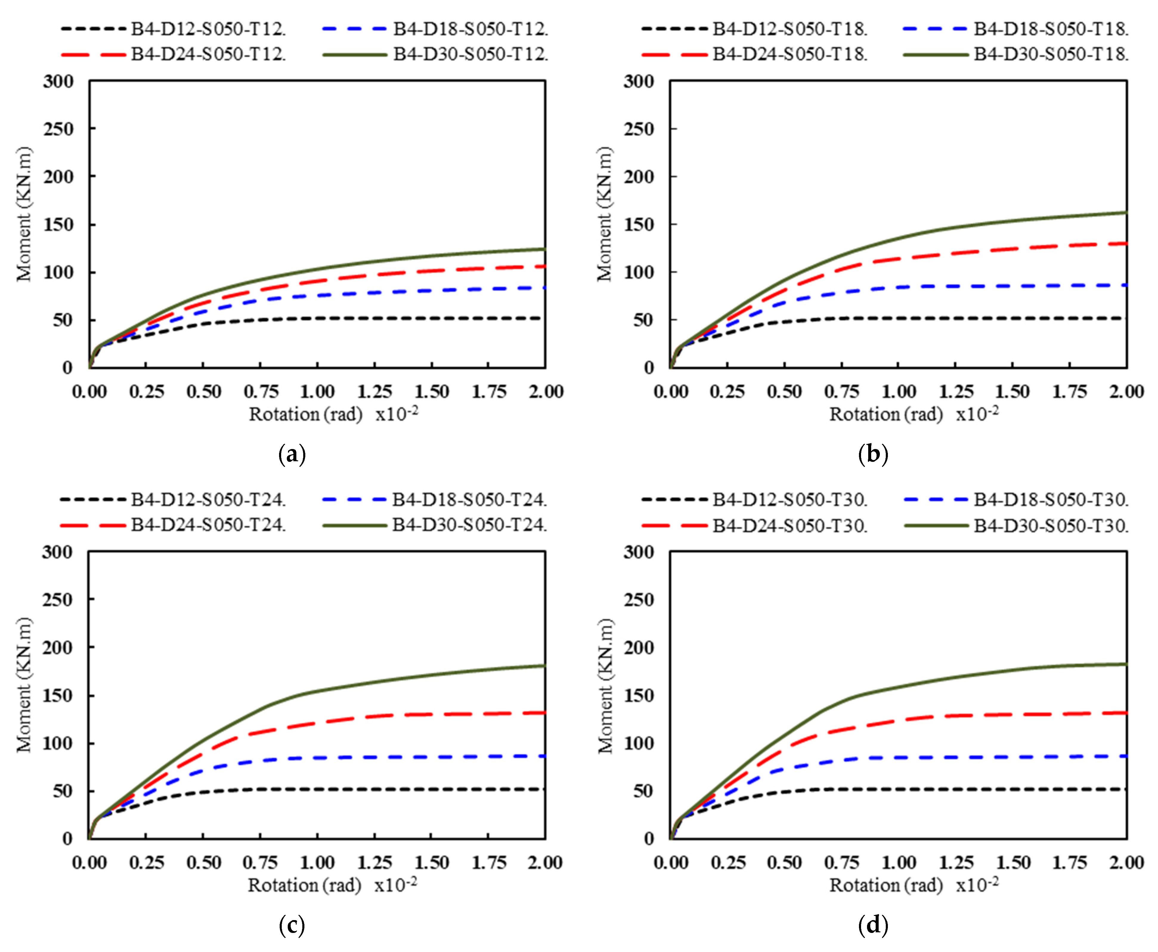
Figure 15.
Effect of the anchor bolt number and spacing (S) on the rotational stiffness for different anchor bolt diameters (D): (a) D = 12 mm, (b) D = 18 mm, (c) D = 24 mm, and (d) D = 30 mm (the base plate thickness of 18 mm).
Figure 15.
Effect of the anchor bolt number and spacing (S) on the rotational stiffness for different anchor bolt diameters (D): (a) D = 12 mm, (b) D = 18 mm, (c) D = 24 mm, and (d) D = 30 mm (the base plate thickness of 18 mm).

Figure 16.
Anchor bolt arrangement according to moment direction.
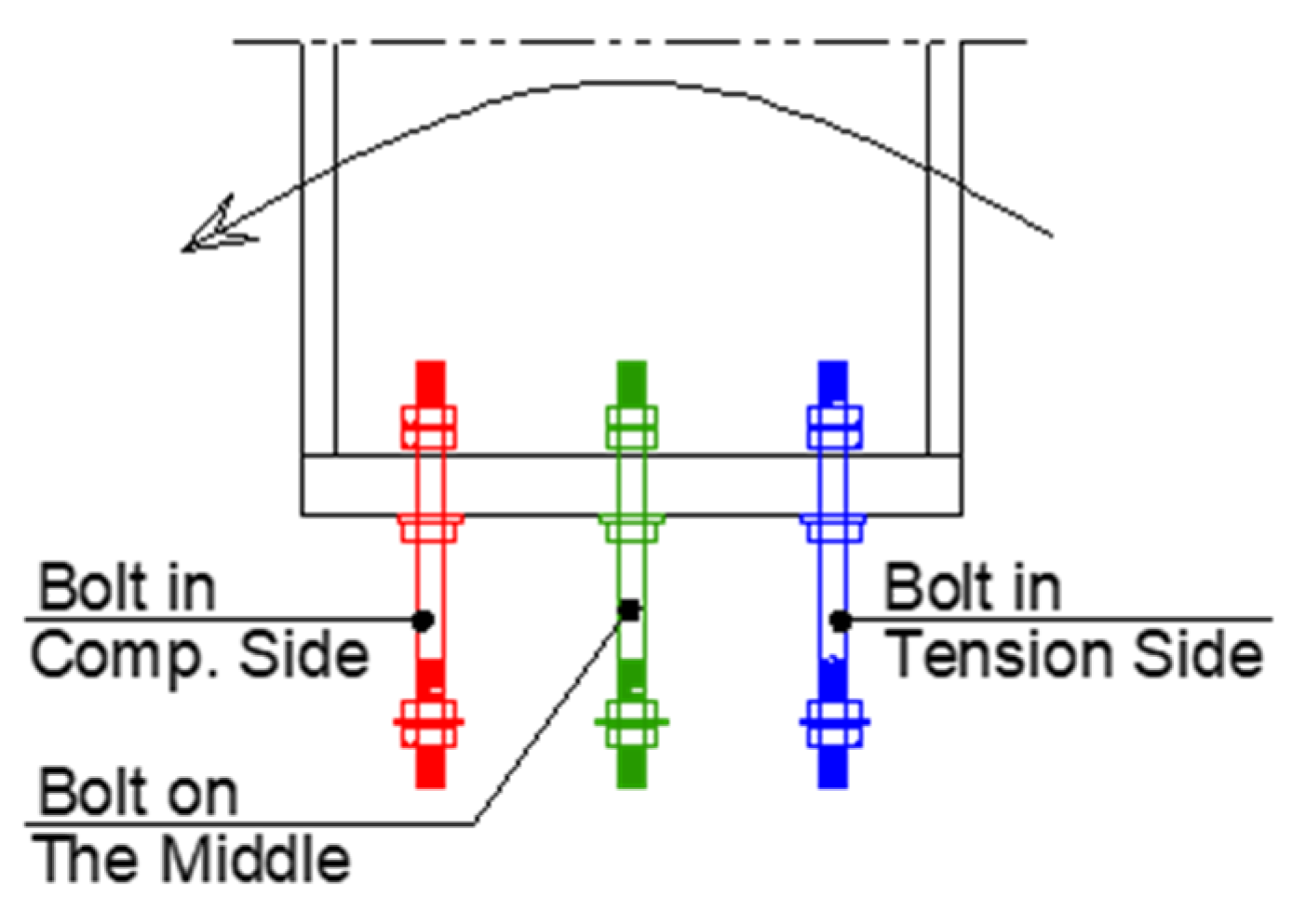
Figure 17.
Piecewise linear idealization of the moment–rotation envelope curves.
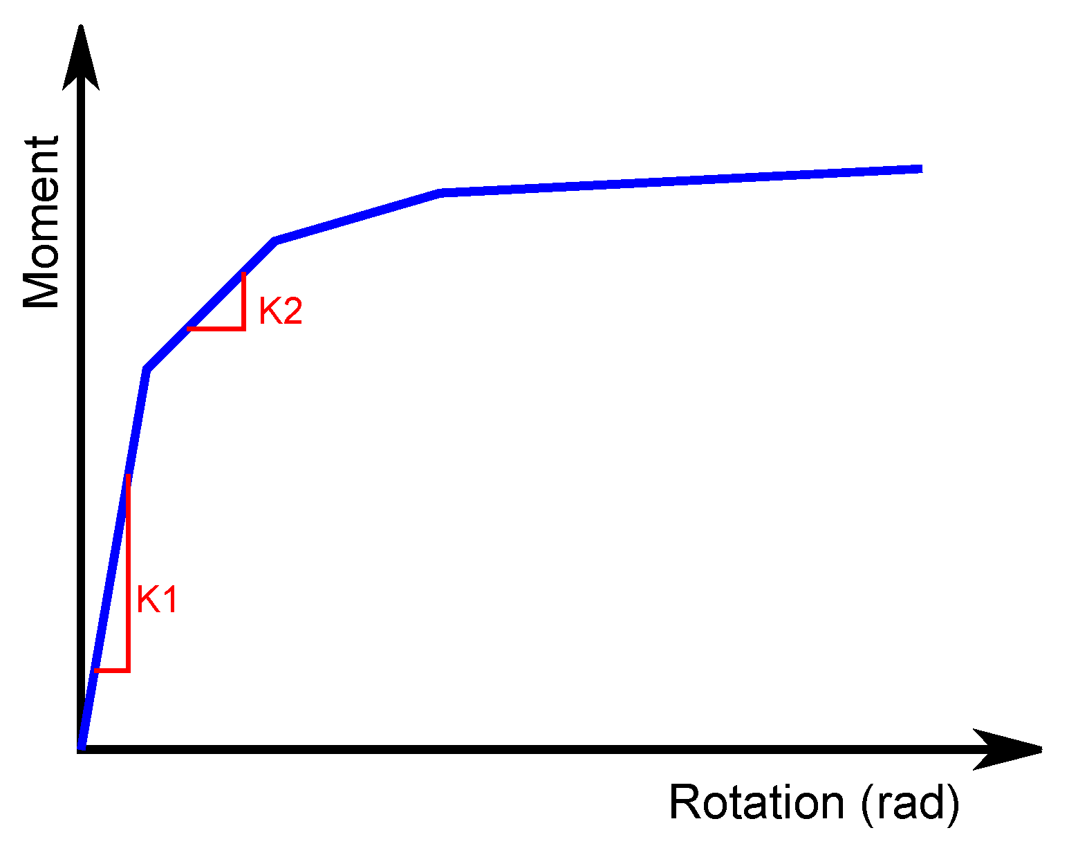
Figure 18.
Piecewise linear idealization for specimens (a) B2-D12-S000-T12 and (b) B6-D12-S150-T30.

Figure 19.
Tension force in the anchor bolts vs. rotation: (a) anchor bolts in the tension side, and (b) anchor bolts in the compression side.
Figure 19.
Tension force in the anchor bolts vs. rotation: (a) anchor bolts in the tension side, and (b) anchor bolts in the compression side.
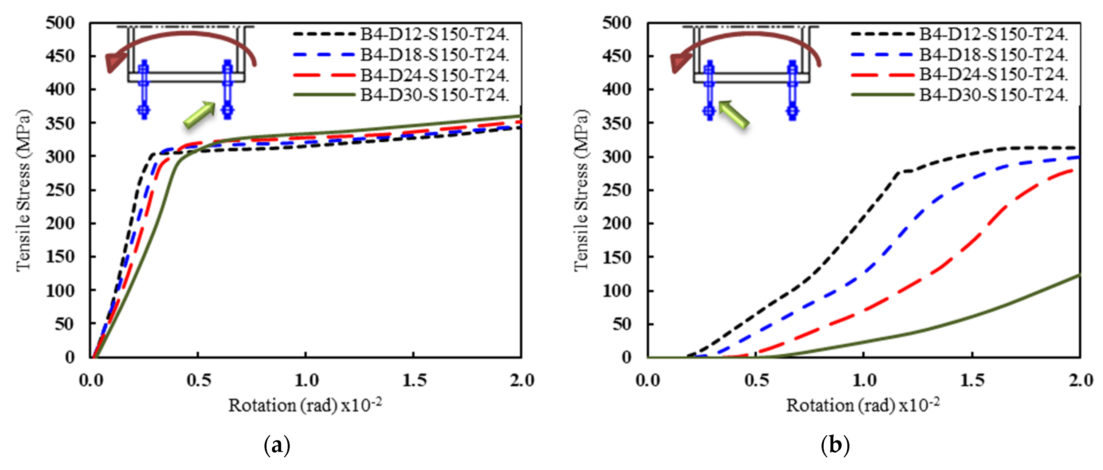
Figure 20.
Tension stresses in the anchor bolts vs. rotation for specimens with T = 24 mm, D = 18 mm, and S = 150 mm. (a) B4-D18-S150-T24 and (b) B6-D18-S150-T24.
Figure 20.
Tension stresses in the anchor bolts vs. rotation for specimens with T = 24 mm, D = 18 mm, and S = 150 mm. (a) B4-D18-S150-T24 and (b) B6-D18-S150-T24.
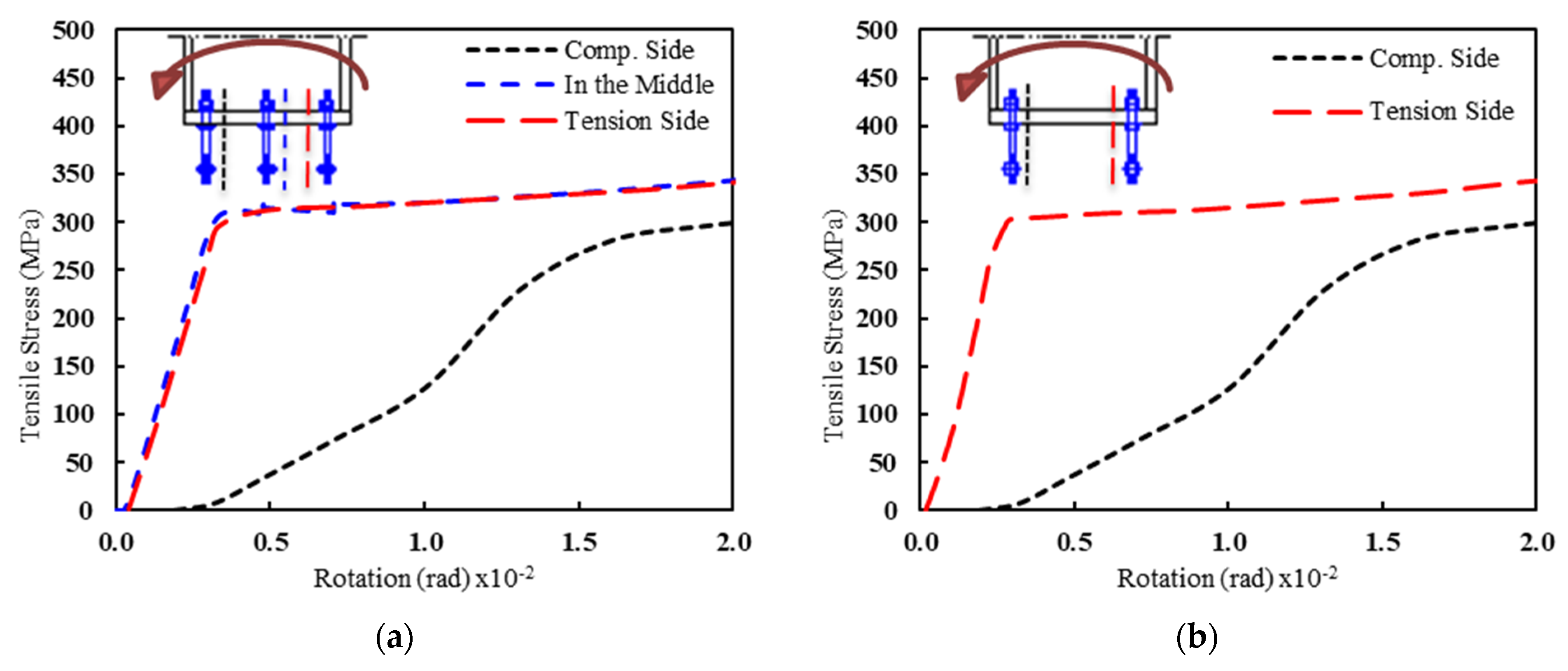
Figure 21.
The rotational stiffness vs. the anchor bolt diameter (d) for different base plate thicknesses and arrangements: (a) two bolts—S = 0, (b) four bolts—S = 50, (c) four bolts—S = 100, (d) four bolts—S = 150, (e) six bolts—S = 100, and (f) six bolts—S = 150.
Figure 21.
The rotational stiffness vs. the anchor bolt diameter (d) for different base plate thicknesses and arrangements: (a) two bolts—S = 0, (b) four bolts—S = 50, (c) four bolts—S = 100, (d) four bolts—S = 150, (e) six bolts—S = 100, and (f) six bolts—S = 150.

Figure 22.
The rotational stiffness vs. the anchor bolt diameter for different anchor bolt arrangement and plate thicknesses: (a) T = 12 mm, (b) T = 18 mm, (c) T = 24 mm, and (d) T = 30 mm.
Figure 22.
The rotational stiffness vs. the anchor bolt diameter for different anchor bolt arrangement and plate thicknesses: (a) T = 12 mm, (b) T = 18 mm, (c) T = 24 mm, and (d) T = 30 mm.


Table 1.
Yielding and ultimate stresses used in the FE analysis [21].
Table 1.
Yielding and ultimate stresses used in the FE analysis [21].
| Steel Column | Steel Base Plate | Anchor Bolt | |
|---|---|---|---|
| fy (MPa) | 392 | 299 | 450 |
| fu (MPa) | 539 | 499 | 865 |
Table 2.
Material characterizations of concrete and grout used in the FE analysis [21].
Table 2.
Material characterizations of concrete and grout used in the FE analysis [21].
| Concrete | Grout | |
|---|---|---|
| fc (MPa) | 24.5 | 49.0 |
Table 3.
Rotational stiffness, energy absorption, piecewise linear idealization, and moment capacity for the analyzed specimens.
Table 3.
Rotational stiffness, energy absorption, piecewise linear idealization, and moment capacity for the analyzed specimens.
| Specimen | K1 | K2 | K * | M ** (KN.m) | E *** (N.m) | Tension Force in Anchor Bolt (KN) | ||
|---|---|---|---|---|---|---|---|---|
| (KN.m)/rad | Comp. Side | Middle | Tension Side | |||||
| B2-D12-S000-T12 | 44,671 | 2933 | 5702 | 38.01 | 204 | - | 35.2 | - |
| B4-D12-S050-T12 | 45,108 | 4788 | 7338 | 48.92 | 243 | 29.3 | - | 38.1 |
| B4-D12-S100-T12 | 66,828 | 6732 | 7321 | 48.81 | 259 | 20.5 | - | 36.8 |
| B4-D12-S150-T12 | 62,684 | 9489 | 7439 | 49.59 | 276 | 10.3 | - | 35.9 |
| B2-D18-S000-T12 | 65,421 | 4672 | 7462 | 49.74 | 239 | - | 75.3 | - |
| B4-D18-S050-T12 | 31,006 | 7213 | 10,078 | 67.18 | 300 | 50.4 | - | 85.9 |
| B4-D18-S100-T12 | 65,666 | 9692 | 11,352 | 75.68 | 345 | 28.9 | - | 85.6 |
| B4-D18-S150-T12 | 62,358 | 15,170 | 11,918 | 79.45 | 394 | 14.9 | - | 84.0 |
| B2-D24-S000-T12 | 48,080 | 5805 | 8386 | 55.91 | 262 | - | 140.9 | - |
| B4-D24-S050-T12 | 41,383 | 10,136 | 11,621 | 77.47 | 338 | 57.2 | - | 153.5 |
| B4-D24-S100-T12 | 63,887 | 12,146 | 13,762 | 91.75 | 396 | 32.8 | - | 159.2 |
| B4-D24-S150-T12 | 48,771 | 20,223 | 17,591 | 117.27 | 510 | 12.8 | - | 161.4 |
| B2-D30-S000-T12 | 31,258 | 7521 | 9349 | 62.32 | 283 | - | 199.0 | - |
| B4-D30-S050-T12 | 29,541 | 11,579 | 13,027 | 86.84 | 374 | 60.9 | - | 213.8 |
| B4-D30-S100-T12 | 30,570 | 16,363 | 15,538 | 103.58 | 441 | 36.6 | - | 243.9 |
| B4-D30-S150-T12 | 65,919 | 24,271 | 20,869 | 139.12 | 589 | 9.7 | - | 256.9 |
| B2-D12-S000-T18 | 44,881 | 3435 | 5716 | 38.11 | 212 | - | 35.8 | - |
| B4-D12-S050-T18 | 38,532 | 6005 | 7666 | 51.10 | 257 | 32.6 | - | 35.4 |
| B4-D12-S100-T18 | 67,251 | 8056 | 7439 | 49.59 | 266 | 23.8 | - | 36.3 |
| B4-D12-S150-T18 | 46,764 | 8987 | 7464 | 49.76 | 280 | 11.5 | - | 35.6 |
| B2-D18-S000-T18 | 20,369 | 5593 | 8061 | 53.74 | 254 | - | 82.3 | - |
| B4-D18-S050-T18 | 28,471 | 10,076 | 11,318 | 75.46 | 337 | 59.7 | - | 82.4 |
| B4-D18-S100-T18 | 67,272 | 12,984 | 11,577 | 77.18 | 372 | 37.4 | - | 82.3 |
| B4-D18-S150-T18 | 49,441 | 18,180 | 11,952 | 79.68 | 411 | 17.0 | - | 82.3 |
| B2-D24-S000-T18 | 38,163 | 7859 | 10,241 | 68.27 | 298 | - | 141.8 | - |
| B4-D24-S050-T18 | 49,381 | 11,121 | 14,360 | 95.73 | 395 | 57.9 | - | 146.9 |
| B4-D24-S100-T18 | 49,506 | 15,183 | 16,752 | 111.68 | 471 | 36.9 | - | 150.9 |
| B4-D24-S150-T18 | 48,717 | 23,417 | 18,054 | 120.36 | 563 | 12.9 | - | 149.0 |
| B2-D30-S000-T18 | 41,008 | 9375 | 11,772 | 78.48 | 331 | - | 219.9 | - |
| B4-D30-S050-T18 | 30,331 | 15,120 | 16,367 | 109.11 | 440 | 61.9 | - | 224.9 |
| B4-D30-S100-T18 | 29,662 | 17,059 | 20,167 | 134.45 | 537 | 34.1 | - | 238.1 |
| B4-D30-S150-T18 | 34,384 | 23,176 | 24,791 | 165.27 | 694 | 5.3 | - | 235.1 |
| B2-D12-S000-T24 | 38,796 | 3914 | 5716 | 38.11 | 213 | - | 34.8 | - |
| B4-D12-S050-T24 | 30,106 | 7455 | 7660 | 51.07 | 262 | 32.1 | - | 34.9 |
| B4-D12-S100-T24 | 41,994 | 8990 | 7482 | 49.88 | 269 | 24.4 | - | 35.1 |
| B4-D12-S150-T24 | 46,991 | 10,065 | 7469 | 49.79 | 282 | 11.7 | - | 35.2 |
| B2-D18-S000-T24 | 41,087 | 6657 | 8273 | 55.15 | 267 | - | 80.0 | - |
| B4-D18-S050-T24 | 29,253 | 10,496 | 11,757 | 78.38 | 352 | 56.9 | - | 79.6 |
| B4-D18-S100-T24 | 49,798 | 14,901 | 11,684 | 77.89 | 381 | 39.3 | - | 79.1 |
| B4-D18-S150-T24 | 49,732 | 19,195 | 11,958 | 79.72 | 417 | 16.9 | - | 79.3 |
| B2-D24-S000-T24 | 48,332 | 8768 | 11,016 | 73.44 | 320 | - | 140.4 | - |
| B4-D24-S050-T24 | 29,130 | 13,930 | 16,050 | 107.00 | 430 | 60.2 | - | 143.6 |
| B4-D24-S100-T24 | 48,427 | 17,907 | 16,928 | 112.85 | 498 | 42.0 | - | 145.6 |
| B4-D24-S150-T24 | 48,548 | 26,380 | 18,047 | 120.31 | 580 | 12.2 | - | 142.5 |
| B2-D30-S000-T24 | 49,366 | 10,939 | 13,212 | 88.08 | 362 | - | 210.6 | - |
| B4-D30-S050-T24 | 29,200 | 15,765 | 18,662 | 124.41 | 486 | 61.3 | - | 201.0 |
| B4-D30-S100-T24 | 65,577 | 24,066 | 22,488 | 149.92 | 594 | 34.1 | - | 232.7 |
| B4-D30-S150-T24 | 48,895 | 30,424 | 25,544 | 170.30 | 739 | 4.0 | - | 234.4 |
| B2-D12-S000-T30 | 41,191 | 3782 | 5717 | 38.12 | 213 | - | 34.9 | - |
| B4-D12-S050-T30 | 38,637 | 6220 | 7775 | 51.83 | 263 | 34.5 | - | 34.8 |
| B4-D12-S100-T30 | 46,811 | 10,576 | 7506 | 50.04 | 270 | 28.1 | - | 35.2 |
| B4-D12-S150-T30 | 42,979 | 11,118 | 7471 | 49.81 | 282 | 11.9 | - | 35.2 |
| B2-D18-S000-T30 | 28,033 | 6562 | 8258 | 55.05 | 272 | - | 78.1 | - |
| B4-D18-S050-T30 | 39,123 | 11,892 | 11,980 | 79.87 | 359 | 66.2 | - | 77.7 |
| B4-D18-S100-T30 | 50,070 | 15,120 | 11,736 | 78.24 | 385 | 41.0 | - | 79.6 |
| B4-D18-S150-T30 | 50,007 | 19,420 | 11,955 | 79.70 | 420 | 17.2 | - | 78.9 |
| B2-D24-S000-T30 | 38,346 | 9598 | 11,450 | 76.34 | 331 | - | 136.9 | - |
| B4-D24-S050-T30 | 41,972 | 15,508 | 16,498 | 109.99 | 448 | 68.1 | - | 141.9 |
| B4-D24-S100-T30 | 43,540 | 20,710 | 16,996 | 113.31 | 508 | 44.9 | - | 140.5 |
| B4-D24-S150-T30 | 47,432 | 28,155 | 18,036 | 120.24 | 586 | 12.0 | - | 141.5 |
| B2-D30-S000-T30 | 28,224 | 12,133 | 13,866 | 92.44 | 379 | - | 185.5 | - |
| B4-D30-S050-T30 | 49,865 | 17,980 | 20,104 | 134.03 | 514 | 66.3 | - | 213.8 |
| B4-D30-S100-T30 | 44,144 | 24,048 | 23,148 | 154.32 | 626 | 35.7 | - | 222.9 |
| B4-D30-S150-T30 | 47,114 | 32,522 | 25,531 | 170.20 | 758 | 3.8 | - | 224.4 |
| B6-D12-S100-T12 | 42,148 | 7753 | 8965 | 59.76 | 289 | 14.7 | 39.3 | 38.1 |
| B6-D18-S100-T12 | 42,164 | 11,908 | 13,085 | 87.24 | 375 | 20.3 | 72.8 | 88.0 |
| B6-D24-S100-T12 | 47,631 | 14,481 | 15,272 | 101.81 | 430 | 23.2 | 97.8 | 158.3 |
| B6-D30-S100-T12 | 54,834 | 17,071 | 17,294 | 115.29 | 479 | 25.0 | 86.9 | 238.5 |
| B6-D12-S100-T18 | 45,144 | 9264 | 9310 | 62.06 | 307 | 19.1 | 35.9 | 35.9 |
| B6-D18-S100-T18 | 46,322 | 14,473 | 14,619 | 97.46 | 424 | 21.8 | 74.0 | 83.6 |
| B6-D24-S100-T18 | 46,420 | 18,044 | 19,207 | 128.05 | 510 | 19.8 | 84.9 | 156.1 |
| B6-D30-S100-T18 | 40,430 | 18,345 | 21,825 | 145.50 | 571 | 18.4 | 89.3 | 236.8 |
| B6-D12-S100-T24 | 48,471 | 9807 | 9364 | 62.42 | 313 | 21.5 | 34.5 | 35.0 |
| B6-D18-S100-T24 | 46,471 | 17,144 | 14,978 | 99.85 | 442 | 23.9 | 71.0 | 79.8 |
| B6-D24-S100-T24 | 46,474 | 20,348 | 20,662 | 137.75 | 554 | 18.4 | 87.5 | 145.5 |
| B6-D30-S100-T24 | 36,858 | 20,730 | 24,764 | 165.09 | 631 | 9.9 | 83.0 | 217.8 |
| B6-D12-S100-T30 | 42,571 | 11,014 | 9401 | 62.67 | 316 | 22.2 | 34.8 | 35.0 |
| B6-D18-S100-T30 | 46,670 | 15,693 | 15,408 | 102.72 | 452 | 25.1 | 75.3 | 78.4 |
| B6-D24-S100-T30 | 39,637 | 22,244 | 21,065 | 140.43 | 574 | 19.3 | 101.9 | 140.2 |
| B6-D30-S100-T30 | 40,733 | 24,926 | 26,491 | 176.61 | 672 | 6.5 | 91.6 | 216.6 |
| B6-D12-S150-T12 | 62,885 | 11,170 | 9195 | 61.30 | 314 | 7.8 | 34.6 | 37.1 |
| B6-D18-S150-T12 | 45,776 | 16,291 | 14,769 | 98.46 | 446 | 8.9 | 74.1 | 85.0 |
| B6-D24-S150-T12 | 47,221 | 22,700 | 19,556 | 130.37 | 548 | 4.9 | 92.2 | 161.5 |
| B6-D30-S150-T12 | 45,205 | 26,739 | 22,904 | 152.69 | 632 | 2.6 | 89.2 | 254.4 |
| B6-D12-S150-T18 | 46,941 | 12,741 | 9438 | 62.92 | 328 | 8.7 | 35.3 | 35.5 |
| B6-D18-S150-T18 | 46,407 | 20,944 | 15,621 | 104.14 | 476 | 7.2 | 70.2 | 82.6 |
| B6-D24-S150-T18 | 45,227 | 24,733 | 21,996 | 146.64 | 623 | 0.8 | 93.2 | 149.7 |
| B6-D30-S150-T18 | 38,689 | 28,841 | 28,365 | 189.10 | 740 | 0.5 | 72.5 | 241.0 |
| B6-D12-S150-T24 | 48,487 | 13,606 | 9443 | 62.95 | 330 | 8.9 | 34.7 | 35.2 |
| B6-D18-S150-T24 | 59,220 | 22,115 | 15,840 | 105.60 | 490 | 4.9 | 74.2 | 79.2 |
| B6-D24-S150-T24 | 46,822 | 27,817 | 22,745 | 151.64 | 651 | 0.6 | 93.9 | 146.5 |
| B6-D30-S150-T24 | 42,561 | 31,725 | 29,327 | 195.51 | 789 | 0.3 | 89.3 | 229.5 |
| B6-D12-S150-T30 | 46,960 | 14,131 | 9433 | 62.89 | 331 | 9.2 | 35.1 | 35.3 |
| B6-D18-S150-T30 | 44,338 | 22,496 | 15,873 | 105.82 | 498 | 6.2 | 74.2 | 79.0 |
| B6-D24-S150-T30 | 48,078 | 29,511 | 23,254 | 155.03 | 670 | 0.4 | 104.8 | 141.4 |
| B6-D30-S150-T30 | 43,544 | 35,171 | 30,360 | 202.40 | 815 | 0.1 | 97.8 | 223.7 |
* Rotational stiffness at H/150 in KN.m/rad; ** Moment in KN.m at H/150; *** Energy absorption in N.m at H/150.
Publisher’s Note: MDPI stays neutral with regard to jurisdictional claims in published maps and institutional affiliations. |
© 2021 by the authors. Licensee MDPI, Basel, Switzerland. This article is an open access article distributed under the terms and conditions of the Creative Commons Attribution (CC BY) license (https://creativecommons.org/licenses/by/4.0/).
Share and Cite
MDPI and ACS Style
Nawar, M.T.; Matar, E.B.; Maaly, H.M.; Alaaser, A.G.; El-Zohairy, A. Assessment of Rotational Stiffness for Metallic Hinged Base Plates under Axial Loads and Moments. Buildings 2021, 11, 368. https://doi.org/10.3390/buildings11080368
AMA Style
Nawar MT, Matar EB, Maaly HM, Alaaser AG, El-Zohairy A. Assessment of Rotational Stiffness for Metallic Hinged Base Plates under Axial Loads and Moments. Buildings. 2021; 11(8):368. https://doi.org/10.3390/buildings11080368
Chicago/Turabian StyleNawar, Mahmoud T., Ehab B. Matar, Hassan M. Maaly, Ahmed G. Alaaser, and Ayman El-Zohairy. 2021. "Assessment of Rotational Stiffness for Metallic Hinged Base Plates under Axial Loads and Moments" Buildings 11, no. 8: 368. https://doi.org/10.3390/buildings11080368
Note that from the first issue of 2016, this journal uses article numbers instead of page numbers. See further details here.