
SmartRock-Based Research on Gyratory Locking Point for Stone Mastic Asphalt Mixture


1
Shanghai Road and Bridge (Group) Co., Ltd., Shanghai 200433, China
2
Shanghai Engineering Research Center of Urban Infrastructure Renewal, Shanghai 200032, China
3
Department of Civil and Environmental Engineering, The University of Tennessee, Knoxville, TN 37996, USA
4
Department of Highway and Railway Engineering, School of Civil Engineering, Beijing Jiaotong University, Beijing 100044, China
*
Authors to whom correspondence should be addressed.
Buildings 2022, 12(2), 97; https://doi.org/10.3390/buildings12020097
Submission received: 10 November 2021
/
Revised: 10 December 2021
/
Accepted: 17 January 2022
/
Published: 20 January 2022
(This article belongs to the Special Issue To Improve Urban Resilience: Cleaner Materials and Technologies towards Sustainable and Green Construction of Buildings)
Abstract
:For gyratory compaction, the concept of the locking point was initially developed to identify the compactability of asphalt mixes and to alleviate potential aggregate crushing in the mold. Most previous studies on the locking point were based on specimens’ height change. Recent studies have indicated that the gyratory locking point of cold mix asphalt mixtures could be determined by the rotation angle range indicator using SmartRock. However, height or rotation angle change ultimately reflects a change in volume. Additionally, there is no clear physical and mechanical connection between the volume change and the gyratory locking point. In this paper, a stone mastic asphalt mixture (SMA 13) was selected for gyratory compaction applying various compaction temperatures. The compaction data were recorded by a SmartRock embedded in different positions. Collected data included stress, rotation angle, and acceleration. The major findings are as follows: (1) the specimen’s locking point could be determined based on a representative stress value when the SmartRock was embedded in the specimen’s center, and the results are close to the traditional evaluation results (LP3 or LP2-2-3); (2) the representative rotation angle value reached a plateau earlier than the representative stress value; (3) the representative acceleration value is not suitable for characterizing the interlocking process during gyratory compaction.
1. Introduction
Compaction is a crucial factor in the construction of asphalt pavement, directly related to the pavement’s quality and durability. Air voids [1,2] and various indicators based on gyratory compaction densification curves, such as the initial number of compactions, the slope of the curve at the initial number of compactions [3], the compaction energy index (CEI), the traffic densification index (TDI) [4], the ratio of compaction times when the air void reaches 2% and 5% [5], the locking point [4], and the densification slope [6], are employed to describe an asphalt mixture’s compactability. Heretofore, researchers had not reached an agreement on the method for determining the compaction state, and the proposed methods were actually based on engineering experience. However, a consensus has been reached: there is a critical state that forms the internal skeleton structure of the asphalt mixture during the compaction process. Before this state, the compaction effort can increase the compaction density; beyond this state, the external input compaction effort cannot effectively increase the asphalt mixture’s density. The concept of the locking point, which is defined as the critical point beyond which the asphalt mixture will obviously become arduous to compact [7], is consistent with researchers’ consensus.
The locking point was initially proposed by William J. Pine, an engineer from the Illinois Department of Transportation [8]. Although the method for determining an asphalt mixture’s locking point has not yet been agreed upon, currently, the relevant research on the locking point mainly focuses on the Marshall compaction and gyratory compaction processes. For Marshall compaction, Polaczyk et al. [9,10,11,12] installed an acceleration sensor on the Marshall hammer to record the dynamic response data during the impact compaction process. The impact locking point was determined by comparing the acceleration pulse signal characteristic, including the peak value and duration, of each impact. When the acceleration pulse signal is stable, the number of impact compactions at that moment is supposed to be the locking point. However, this method artificially compares the acceleration pulse signal of each impact, and the data processing cost is high. In addition, factors such as signal noise and human interception errors will affect the accuracy and stability of the evaluation result. Therefore, Cheng et al. [13,14] proposed an improved evaluation method. To construct the acceleration peak compaction curve after filtering and smoothing the collected initial data, the modified method can sufficiently characterize the feature of the asphalt mixture’s compaction process, quickly determine the impact locking point, and avoid the potential of misjudgment in Polaczyk et al.’s method.
For gyratory compaction, the locking point is mainly identified according to the height change of the asphalt mixture sample. The Alabama Department of Transportation defines the locking point as a height change of less than 0.1 mm of the specimen between two consecutive compaction times [15]. The definition of the locking point in Georgia is the first number of gyrations when the height of the specimen does not change for three consecutive times (LP3) [16]. Subsequently, Anderson and Bahia proposed a modified method that defined the locking point as the number of the first gyration when the heights of three consecutive gyrations were the same and when there were previously two groups of two equal, consecutive heights (LP2-2-3) [17]. The Alabama Department of Transportation also recommends several other methods to distinguish the locking point, such as (1) the number of gyrations with the same specimen height for the first two consecutive gyrations (Locking Point 2-1), (2) the second occurrence of two successive gyrations with the same specimen height (Locking Point 2-2), and (3) the third occurrence of two consecutive gyrations with the same specimen height (Locking Point 2-3). To sum up, the abovementioned locking point evaluation methods only depend on the height change of the specimen during the compaction process. However, the relationship between the locking point and the internal structure evolution is not clear. Therefore, there is still a lack of consensus for a single identification method for determining the gyratory locking point.
Departing from the traditional method of using the specimen’s height change to determine the gyratory locking point, SmartRock, as an innovative method, was employed to describe an asphalt mixture’s compactability. SmartRock is a sensor integrating acceleration, stress, temperature, and four-element (rotational attitude) test elements. Utilizing Bluetooth BLE technology (location recognition algorithm based on Bluetooth low-energy technology) and the Kalman filtering mechanism, the SmartRock sensor can effectively improve the accuracy of original data by reducing the accumulation of errors in the quadratic acceleration integration (drift problem) [18]. Initially, Huang and Liu developed SmartRock to be applied in the railway industry and successfully described the movement behavior characteristics of railway ballast particles under loading [19]. Compared with the widespread use of SmartRock in the railway industry, the application of SmartRock in asphalt mixtures during compaction is still in the exploratory stage. Limited by the maximum particle size of the asphalt mixture, the researchers reduced the size of the SmartRock [20,21,22,23,24,25]. Wang et al. [20] employed a SmartRock embedded into a cold mix asphalt mixture specimen during gyratory compaction to record the aggregate’s movement posture change data, and the results of comparing the different SmartRocks’ embedded positions demonstrated that the stable-stage characteristics were more prominent when the SmartRock was embedded in the specimen center. Dan et al. [26] also attempted to use the SmartRock to test the change law of aggregate contact stress during gyratory compaction for five quintessential selected asphalt mixtures and found that the stress ratio curve could reflect the mechanical change characteristics of the mixture skeleton structure from a meso-scale perspective. In summary, previous studies have demonstrated that there is no effective method for determining a hot mix asphalt mixture’s gyratory locking point based on SmartRock.
Although the evaluation method is still not agreed upon, the academic community has recognized the concept of the locking point. Based on SmartRock, the objective of this study was to analyze the response characteristics of a hot mix asphalt mixture during gyratory compaction from a meso-scale perspective and develop an improved method for determining the locking point at the mechanical level. To achieve this goal, a skeleton dense-graded asphalt mixture (SMA 13) was selected to study the response characteristics of SmartRock at different embedded positions and compaction temperatures. To verify the applicability of the new method for determining the locking point, correlation analysis with the traditional approach based on the specimen’s height change was indispensable.
2. Methods
2.1. Materials
A stone mastic asphalt mixture (SMA 13) with a nominal maximum particle size of 13 mm was selected from the new construction project of the Jiangpu Road River Crossing Tunnel in Shanghai. The indexes of the modified asphalt are listed in Table 1. Additionally, the basic technical indicators of the coarse aggregates and filler are listed in Table 2 and Table 3. The primary indicators of the aggregates and filler satisfy the corresponding requirements in Technical Specifications for Construction of Highway Asphalt Pavements (JTG F40-2004) [27]. Table 4 shows the SMA 13 mixture’s production composition proportion, and the aggregate grading design is shown in Figure 1.
2.2. Experimental Equipment
2.2.1. SmartRock
SmartRock, with a similar density to aggregates, as shown in Figure 2, is an ultra-small (23 × 23 × 23 mm) and high temperature-resistant sensor developed for monitoring and predicting the force, deformation, stability, etc., in railway subgrades and highway pavements. SmartRock can collect and monitor original data in real time, including standard time, temperature, internal normal stress, 3D Euler angle in a geodetic coordinate system, shear strain, and high-precision three-axis acceleration. Utilizing Bluetooth Low Energy to transmit data to a portable receiver or a roadside signal collector (STRDAL GLOBAL) and uploading it to the cloud storage in real time, users can check and download measurement data at any time.
Each SmartRock possesses a unique identification code, and a calibration procedure is indispensable to ensure that the corresponding relationship between temperature and stress follows Equation (1).
where U is the voltage signal (V) recorded during compaction, U0 is the voltage signal (V) before compaction, f is the stress value (N/m2), A is the SmartRock’s stress area (m2), t is the measurement temperature (°C), and a, b, and c are calibration coefficients as listed in Table 5.
2.2.2. Gyratory Compactor
The specimens were compacted in a gyratory compactor produced by Pine Instrument Company, as shown in Figure 3. The gyratory compaction process was implemented with a stable pressure of 600 kPa, a rate of 30 gyrations per minute, an angle of 1.25°, and a total number of 100 gyrations.
2.3. Methods
2.3.1. Data Collection Process
As shown in Figure 4, the data collection system consists of three modules: data, communication, and design software. To ensure SmartRock can work under high temperatures during the modified asphalt mixture compaction, adding a thermal insulation layer to the exterior is indispensable.
2.3.2. Coordinate System Conversion
The data collected by SmartRock are based on the local coordinate system, as shown in Figure 5. However, the three-axis direction of the local coordinate system changes with the movement of SmartRock. All the original data collected should be converted into a fixed global coordinate system to facilitate the unified data analysis and comparison. In the global coordinate system, the X- and Y-axes represent the horizontal direction, and the Z-axis represents the vertical direction.
The rotation matrix from the local coordinate system to the global coordinate system is shown in Equation (2), where ϕ, θ, and ψ are the rotating Euler angles about the X-axis, Y-axis, and Z-axis recorded by SmartRock in real time.
2.3.3. Experiment Schedule
The experiment schedule for this study is listed in Table 6. The SMA 13 mixture specimens with a single weight of 4.8 kg were compacted with 100 gyrations. Additionally, the original data, including stress, acceleration, and rotation angle, were recorded under various compaction temperatures and the SmartRock’s embedded positions. The sampling frequency was 10 ms for stress and acceleration, and 60 ms for rotation angle. In addition, three sets of parallel trials were conducted for each specimen test in Table 6, and the SmartRock was embedded in the specimen’s top, center, or bottom, as shown in Figure 6.
2.3.4. Gyratory Locking Point Determination
Stress [28,29,30], acceleration, and rotation angle were selected to determine the gyratory locking point using the same method. Taking the stress index as an example in Figure 7, firstly, the original data were converted to frequency domain values by a fast Fourier transform, as shown in Figure 7b; then, the frequency domain values were processed through the Butterworth bandpass filter with a frequency range of 0.4–0.6 Hz to reduce noise, as shown in Figure 7c; afterward, the representative stress value signed as RS for each gyration was calculated according to the characteristics of the filtered data in the time domain, as shown in Figure 7d; lastly, the critical point when the constructed representative stress value reaches a plateau was defined as the gyratory locking point, as shown in Figure 7e.
Theoretically, after a critical interlocking state of the asphalt mixture, the response value’s fluctuation should reach a plateau. Therefore, the representative stress value (Rs) is defined to describe the relative stress change range within one compaction cycle. Additionally, the representative stress value can be calculated according to Equation (3). Similarly, the representative acceleration or rotation angle value can be calculated.
where RS is the representative stress value, as shown in Figure 7d, Smax and Smin represent the maximum and minimum stresses for each gyration cycle, and Smean is the average of the maximum and minimum stresses in one gyration cycle.
3. Results and Discussion
3.1. Representative Stress Value When SmartRocks Were Embedded in Various Positions
In Figure 8, the horizontal axis represents the number of gyrations, and the vertical axis is the representative triaxial stress (X-axis, Y-axis, and Z-axis) values (RS) for each gyratory compaction, indicating the relative stress change range. The SmartRocks were embedded in various positions to collect original data during gyratory compaction with a temperature of 170 °C. When the SmartRock was embedded in the specimen’s upper part, as shown in Figure 8a, the representative triaxial stress values increased significantly, reaching a peak value at approximately 9 gyrations, then fluctuating frequently before a critical point at 84 gyrations, and lastly arriving at a plateau. Similarly, when the SmartRock was embedded in the specimen’s center part, as shown in Figure 8b, or lower part, as shown in Figure 8c, the results indicate that the representative stress values showed a noticeable increase first to a peak value, then frequent fluctuations, and finally a stable state after 94 or 91 gyrations, respectively. According to the definition of the gyration locking point in this study, for the SMA 13 mixture with a compaction temperature of 170 °C, the aggregates in the upper part reached the interlocking state (84 gyrations) first, followed by those in the lower part (91 gyrations), and lastly those in the center part (94 gyrations).
In the earlier compaction stage, the aggregates were relatively loose, contributing to significant growth in the representative stress value. However, in the mid-stage of compaction, the aggregates were continuously rearranged under the action of the gyratory compaction effort. Before the skeleton structure reached stability, the representative stress value exhibited frequent fluctuations. In the last compaction stage, the internal stable skeleton structure of the asphalt mixture was formed, and the locking point could be determined. Furthermore, the analysis results demonstrate that the internal interlocking sequence of the asphalt mixture was the upper part first, then the lower part, and lastly the center part. The reason might be that the aggregates are constrained by external boundary conditions at the top and bottom of the specimen, which makes it easier to achieve structural interlocking. The locking point determined in the center part shows that the specimen reached an interlocked state.
3.2. Representative Stress Value with Different Compaction Temperatures
To consider the effect of the compaction temperature, representative stress values are shown in Figure 9. It can also be seen that the representative stress value experienced a rapid increase and frequent fluctuation and reached a stable plateau at a different critical point. With a compaction temperature of 180 °C, the gyratory locking point was determined at 89 gyrations. With compaction temperatures of 160 °C and 170 °C, the gyratory locking points were close at 93 and 94 gyrations. These results may indicate that the aggregates reached an interlocking state earlier with a higher compaction temperature. The time–temperature equivalent characteristics of asphalt could explain this phenomenon. The higher the temperature, the shorter the time required to reach the equal compaction state.
In addition, this conclusion could be verified by the results of the traditional gyratory locking point method based on the specimen’s height change in Figure 10. The horizontal axis is the compaction temperature, and the vertical axis is the number of gyrations at the locking point. This demonstrates that the specimen reached the locking point earlier at 90 gyrations with a compaction temperature of 180 °C, when the SmartRock was embedded in the specimen’s center.
3.3. Gyratory Locking Point Comparison between the Traditional Method and New Method
In the locking point histogram shown in Figure 11, the vertical axis represents the number of gyrations at the locking point, and the horizontal axis represents various positions of the SmartRock. With the compaction temperature of 170 °C, the locking point determined by the new method based on R’s change is consistent with the result of the traditional approach based on the specimen’s height change (LP3 or LP2-2-3) when the SmartRock was embedded in the center part. However, the gyratory locking points have results that are inconsistent with the traditional method when SmartRocks were embedded in various positions. The SmartRock’s size, which is nearly twice the maximum nominal particle size of the SMA 13 mixture, might be the primary cause. When the SmartRocks are located in the upper and lower parts, they are more affected by the external boundary than when they are located in the middle, which might directly affect the locking point’s evaluation results based on the specimen’s height change.
3.4. Representative Rotation Angle Value
Similarly, the representative rotation angle value with different compaction temperatures when SmartRocks were embedded in the middle of the specimen is analyzed in Figure 12. In general, the representative rotation angle value trend is consistent with that of the representative stress value. Based on the representative rotation angle value change, the gyratory locking points were determined at 90 gyrations, 90 gyrations, and 85 gyrations, with the corresponding compaction temperatures of 160 °C, 170 °C, and 180 °C. The results indicate that the aggregates were interlocked first at the higher compaction temperature. To compare with Wang et al.’s study [21], using relative rotation curves to qualitatively analyze the locking point, the representative rotation angle value can better describe the gyratory compaction process and quantify the locking point.
Moreover, as shown in Figure 13, it can be seen that the locking points determined by the representative rotation angle value were reached earlier than those specified by the representative stress value. The representative rotation angle value essentially reflects the specimen’s volume change during compaction, whereas the representative stress value is related to the specimen’s overall stiffness. In other words, when the compacted volume remains constant, the stiffness still has the potential for change.
3.5. Representative Acceleration Value
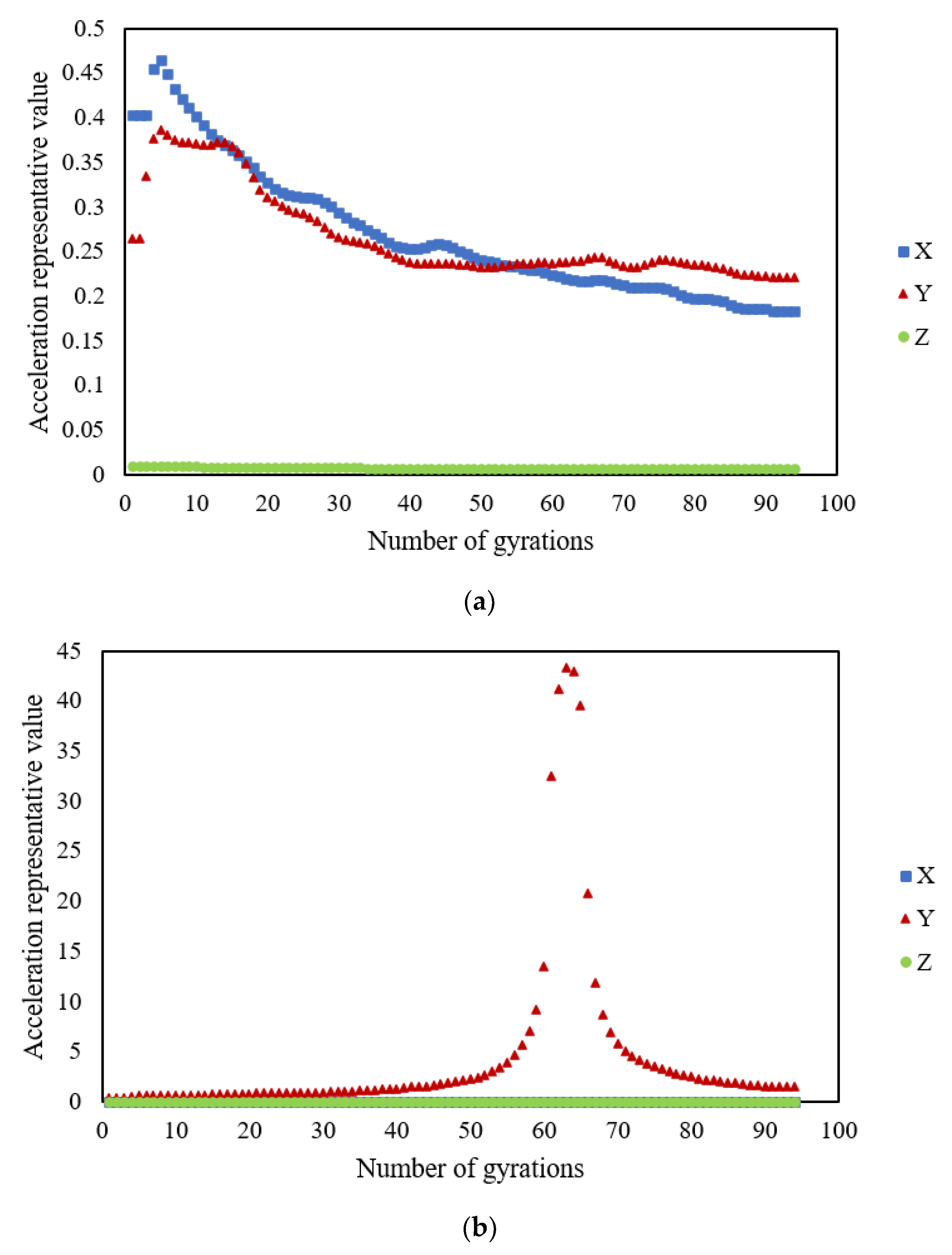
Unlike the representative stress and rotation angle values, the representative acceleration value indicates a different trend. Figure 14 shows the results for when the SmartRocks were embedded in the specimen’s center with various compaction temperatures. The representative Z-axis (vertical direction) acceleration value shows no change during gyratory compaction. The primary reason is that the gyratory compactor works with a vertical stress of 600 kPa, at a constant speed of 30 rotations per minute. In Figure 14a, the representative X-axis or Y-axis (horizontal direction) acceleration value increases first to a peak value at around 5 gyrations and then gradually reduces to reach a plateau at 91 gyrations. In Figure 14b, the representative Y-axis acceleration value mutates at around 63 gyrations; however, the representative X-axis and Z-axis acceleration values maintain a similar stable trend entirely. Unlike Figure 14a,b, Figure 14c demonstrates that the representative X-axis or Y-axis acceleration value has a different trend. Moreover, the number of gyrations obtained from the analysis result is less than 100, indicating that the data packet loss problem occurred during the original data collection. Overall, the representative acceleration value is unsuitable to be used for determining the gyratory locking point.
3.6. Limitations and Recommendations
As a preliminary study, there are still some inevitable limitations, as follows: (1) only the stress index was calibrated during compaction, and the influence of temperature change on the SmartRock’s signal was taken into account during the data acquisition; (2) the size and shape of the SmartRock are quite different from the actual aggregates in the SMA 13 mixture, which may lead to a particular impact on the test results. In further study, the structural type of asphalt mixtures, asphalt content, specimen size, and other factors affecting compactability should be considered to verify the internal mesostructure evolution characteristics of the asphalt mixture. Furthermore, SmartRock used in the railway industry needs to be upgraded for research on asphalt pavement. Achieving a smaller size, higher temperature resistance, etc., should be the development goal. In addition, 3D printing technology could be considered to simulate the SmartRock’s shell shape.
4. Summary and Conclusions
In this study, SmartRock-based research on the gyratory locking point for the SMA 13 mixture was designed and analyzed considering the SmartRock’s embedded positions, evaluation parameters in the vertical or horizontal direction, and compaction temperatures. The conclusions are summarized as follows:
- (1)
- The representative value of the triaxial stress reached the final stable state simultaneously, and the aggregates’ interlocking sequence was the upper part first, then the lower part, and lastly the middle part. The specimen’s locking point determined by the result of the center-positioned SmartRock is more reasonable.
- (2)
- The higher the compaction temperature, the earlier the locking point was reached. In addition, the locking points determined by the representative triaxial stress value were closer to the traditional evaluation results (LP3 or LP2-2-3).
- (3)
- SmartRocks embedded in the specimen’s upper and lower parts had a more significant impact on the results of the traditional locking point (LP3 or LP2-2-3). When the SmartRock was located in the middle, there was a more negligible effect on the asphalt mixture’s interlocking results during gyratory compaction.
- (4)
- The representative rotation angle value reached a plateau earlier than the representative stress value, which means that the mechanical index interlocking lags behind the volume index interlocking.
- (5)
- Overall, the representative acceleration value is unsuitable for characterizing the interlocking process during gyratory compaction. Due to the gyratory compactor working at a constant speed and a specific angle, the representative horizontal direction (X-axis or Y-axis) acceleration value changes with no significant regularity. In addition, there is an original data packet loss problem during acceleration data collection, leading to incomplete acceleration peak data. A feasible way to solve this problem might be to enhance the Bluetooth transmission signal.
Author Contributions
Conceptualization, T.W. and Z.C.; methodology, Z.C. and D.Z.; software, D.Z.; validation, S.X.; formal analysis, S.X.; investigation, Z.C.; resources, Z.C.; data curation, Z.C.; writing—original draft preparation, Z.C.; writing—review and editing, P.A.P.; project administration, Z.C.; funding acquisition, T.W. and Z.C. All authors have read and agreed to the published version of the manuscript.
Funding
This research was funded by the Shanghai Science and Technology Committee (Grant No. 20dz1202100) and (20DZ2251900) and the National Natural Science Foundation of China (Grant Number: 52108392).
Institutional Review Board Statement
Not applicable.
Informed Consent Statement
Not applicable.
Data Availability Statement
This statement has been excluded.
Conflicts of Interest
The authors declare no conflict of interest.
References
- Brown, E.R. Density of Asphalt Concrete-How Much is Needed? In Proceedings of the Transportation Research Board, Washington, DC, USA, 1 January 1990.
- Huber, G.A.; Heiman, G.H. Effect of asphalt concrete parameters on rutting performance: A field investigation. In Proceedings of the Association of Asphalt Paving Technologists, Ottawa, ON, Canada, 31 January 1986. [Google Scholar]
- Mcgennis, R.B.; Anderson, R.M.; Kennedy, T.W.; Solaimanian, M. Background of Superpave Asphalt Mixture Design and Analysis. National Asphalt Training Center Demonstration Project 101; The Asphalt Institue: Lexington, KY, USA, 1995. [Google Scholar]
- Bahia, H.U.; Friemel, T.P.; Peterson, P.A. Optimization of constructibility and resistance to traffic: A new design approach for HMA using the superpave compactor. J. Assoc. Asph. Paving Technol. 1998, 67, 189–232. [Google Scholar]
- Mallick, R.B. Use of Superpave Gyratory Compactor To Characterize Hot-Mix Asphalt. Transp. Res. Rec. 1999, 1681, 86–96. [Google Scholar] [CrossRef]
- Masad, E.; Kassem, E.; Chowdhury, A.; You, Z. A Method for Predicting Asphalt Mixture Compactability and Its Influence On Mechanical Properties; Texas Transportation Institute, The Texas A&M University System: College Station, TX, USA, 2009. [Google Scholar]
- Vavrik, W.R.; Carpenter, S.H. Calculating Air Voids at Specified Number of Gyrations in Superpave Gyratory Compactor. Transp. Res. Rec. 1998, 1630, 117–125. [Google Scholar] [CrossRef]
- Vavrick, W.R.; Huber, G.; Pine, W.J.; Bailey, R. Bailey Method Summarized for Gradation Selection in Hot-Mix Asphalt Design. In Proceedings of the Transportation Research Board, Washington, DC, USA, 8 October 2002. [Google Scholar]
- Polaczyk, P.; Han, B.; Huang, B.; Jia, X.; Shu, X. Evaluation of the hot mix asphalt compactability utilizing the impact compaction method. Constr. Build. Mater. 2018, 187, 131–137. [Google Scholar] [CrossRef]
- Polaczyk, P.; Huang, B.; Shu, X.; Gong, H. Investigation into Locking Point of Asphalt Mixtures Utilizing Superpave and Marshall Compactors. J. Mater. Civ. Eng. 2019, 31, 04019188. [Google Scholar] [CrossRef]
- Polaczyk, P.; Shu, X.; Gong, H.; Huang, B. Influence of aggregates angularity on the locking point of asphalt mixtures. Road Mater. Pavement Des. 2019, 20, S183–S195. [Google Scholar] [CrossRef]
- Polaczyk, P.; Han, B.; Gong, H.; Ma, Y.; Huang, B. Influence of Aggregate Gradation on the Compactability of Asphalt Mixtures Utilizing Locking Point. J. Mater. Civ. Eng. 2021, 33, 04021005. [Google Scholar] [CrossRef]
- Cheng, Z.; Jia, X.; Jiang, H.; Hu, W.; Huang, B. Quantification of impact compaction locking point for asphalt mixture. Constr. Build. Mater. 2021, 302, 124410. [Google Scholar] [CrossRef]
- Zhiqiang, C.; Andrzej, P.P.; De, Z.; Wei, H.; Baoshan, H. A method for determining impact locking point of asphalt mixtures based on dynamic response. J. Cent. South Univ. 2021, 52, 2232–2245. [Google Scholar]
- Alabama Department of Transportation. Special Provision No. 02-0360(5)-2004—Amendment for Section 424; Alabama Standard Specifications: Montgomery, AL, USA, 2004. [Google Scholar]
- Georgia Department of Transportation. Special Provision-Section 828—Hot-Mix Asphaltic Concrete Mixtures; Georgia Standard Specifications: Atlanta, GA, USA, 2003. [Google Scholar]
- Anderson, R.M.; Turner, P.A.; Peterson, R.L. Relationship of Superpave Gyratory Compaction Properties to HMA Rutting Behavior; Transportation Research Board Executive Committee: Washington, DC, USA, 2002. [Google Scholar]
- Liu, S.; Qiu, T.; Qian, Y.; Huang, H.; Tutumluer, E.; Shen, S. Simulations of large-scale triaxial shear tests on ballast aggregates using sensing mechanism and real-time (SMART) computing. Comput. Geotech. 2019, 110, 184–198. [Google Scholar] [CrossRef]
- Liu, S.; Huang, H.; Qiu, T.; Gao, L. Comparison of Laboratory Testing Using SmartRock and Discrete Element Modeling of Ballast Particle Movement. J. Mater. Civ. Eng. 2017, 29, D6016001. [Google Scholar] [CrossRef]
- Wang, X.; Shen, S.; Huang, H.; Almeida, L.C. Characterization of particle movement in Superpave gyratory compactor at meso-scale using SmartRock sensors. Constr. Build. Mater. 2018, 175, 206–214. [Google Scholar] [CrossRef]
- Wang, X.; Shen, S.; Huang, H.; Zhang, Z. Towards smart compaction: Particle movement characteristics from laboratory to the field. Constr. Build. Mater. 2019, 218, 323–332. [Google Scholar] [CrossRef]
- Dan, H.-C.; Yang, D.; Liu, X.; Peng, A.-P.; Zhang, Z. Experimental investigation on dynamic response of asphalt pavement using SmartRock sensor under vibrating compaction loading. Constr. Build. Mater. 2020, 247, 118592. [Google Scholar] [CrossRef]
- Shi, B.; Shen, S.; Liu, L.; Wang, X. Estimation of Vehicle Speed from Pavement Stress Responses Using Wireless Sensors. J. Transp. Eng. Part B Pavements 2021, 147, 04021028. [Google Scholar] [CrossRef]
- Wang, X.; Shen, S.; Huang, H. Meso-Scale Kinematic Responses of Asphalt Mixture in Both Field and Laboratory Compaction. Transp. Res. Rec. J. Transp. Res. Board 2021, 2675, 03611981211009222. [Google Scholar] [CrossRef]
- Zhang, C.; Shen, S.; Huang, H.; Wang, L. Estimation of the Vehicle Speed Using Cross-Correlation Algorithms and MEMS Wireless Sensors. Sensors 2021, 21, 1721. [Google Scholar] [CrossRef]
- Dan, H.-C.; Yang, D.; Zhao, L.-H.; Wang, S.-P.; Zhang, Z. Meso-scale study on compaction characteristics of asphalt mixtures in Superpave gyratory compaction using SmartRock sensors. Constr. Build. Mater. 2020, 262, 120874. [Google Scholar] [CrossRef]
- Ministry of Transport of the People’s Republic of China. Technical Specifications for Construction of Highway Asphalt Pavements; The People’s Communication Publishing Company: Beijing, China, 2004; Volume JTG F40-2004. [Google Scholar]
- Jiang, X.; Zhang, M.; Xiao, R.; Polaczyk, P.; Bai, Y.; Huang, B. An investigation of structural responses of inverted pavements by numerical approaches considering nonlinear stress-dependent properties of unbound aggregate layer. Constr. Build. Mater. 2021, 303, 124505. [Google Scholar] [CrossRef]
- Zhang, D.; Cheng, Z.Q.; Geng, D.J.; Xie, S.J.; Wang, T. Experimental and numerical analysis on mesoscale mechanical behavior of coarse aggregates in the asphalt mixture during gyratory compaction. Processes 2021, 10, 47. [Google Scholar] [CrossRef]
- Jiang, X.; Gabrielson, J.; Huang, B.; Bai, Y.; Polaczyk, P.; Zhang, M.; Hu, W.; Xiao, R. Evaluation of inverted pavement by structural condition indicators from falling weight deflecometer. Constr. Build. Mater. 2021, 319, 125991. [Google Scholar] [CrossRef]
Figure 1.
Production grading curve.
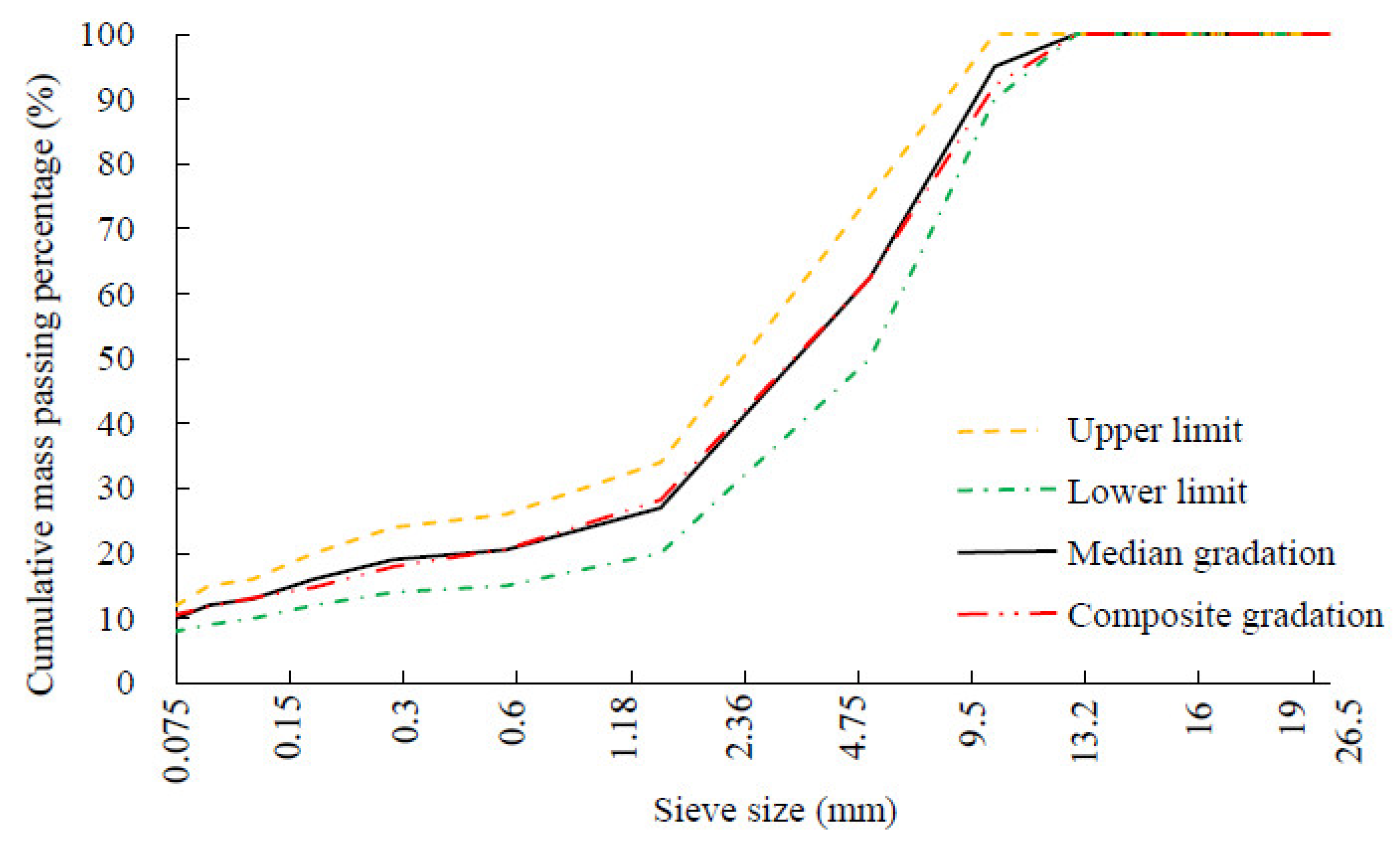
Figure 2.
SmartRock.
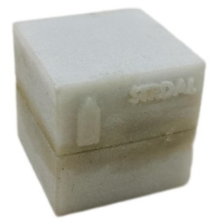
Figure 3.
Gyratory compactor.
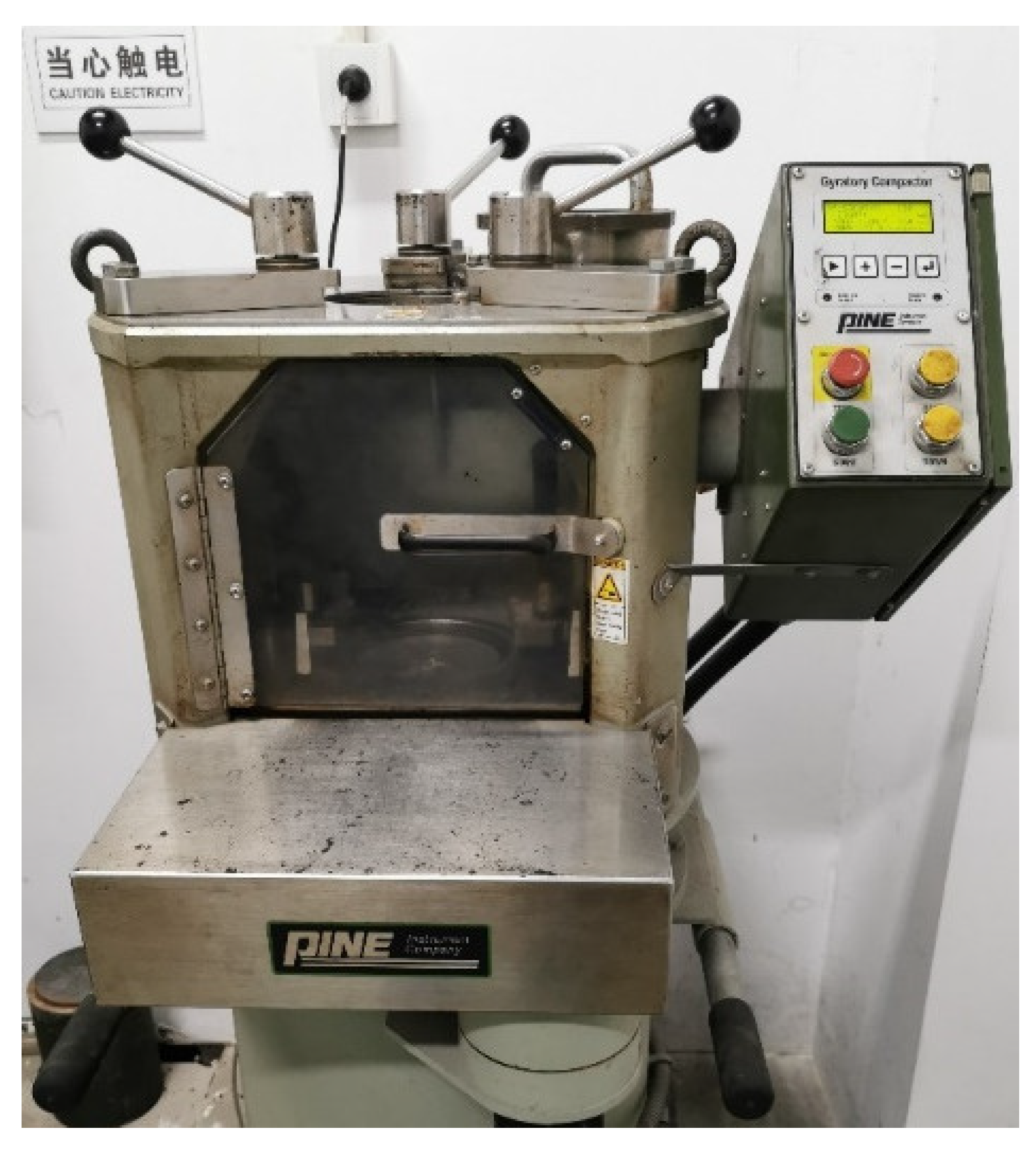
Figure 4.
Data collection system.

Figure 5.
Local coordinate system.

Figure 6.
SmartRock embedded in SAM 13 mixture specimen: (a) top, (b) center, and (c) bottom.
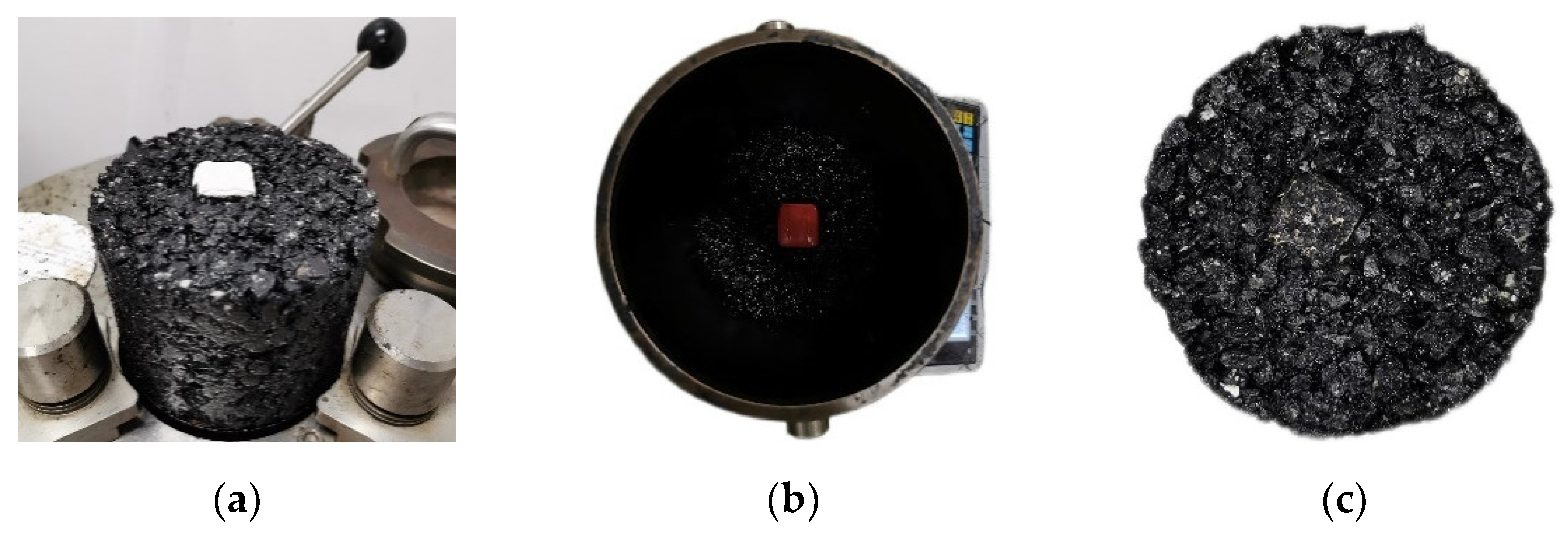
Figure 7.
Gyratory locking point determination procedure: (a) original data in the time domain, (b) original data in the frequency domain, (c) post-processed data in the frequency domain, (d) post-processed data in the time domain, and (e) Z-axis representative stress value curve.
Figure 7.
Gyratory locking point determination procedure: (a) original data in the time domain, (b) original data in the frequency domain, (c) post-processed data in the frequency domain, (d) post-processed data in the time domain, and (e) Z-axis representative stress value curve.

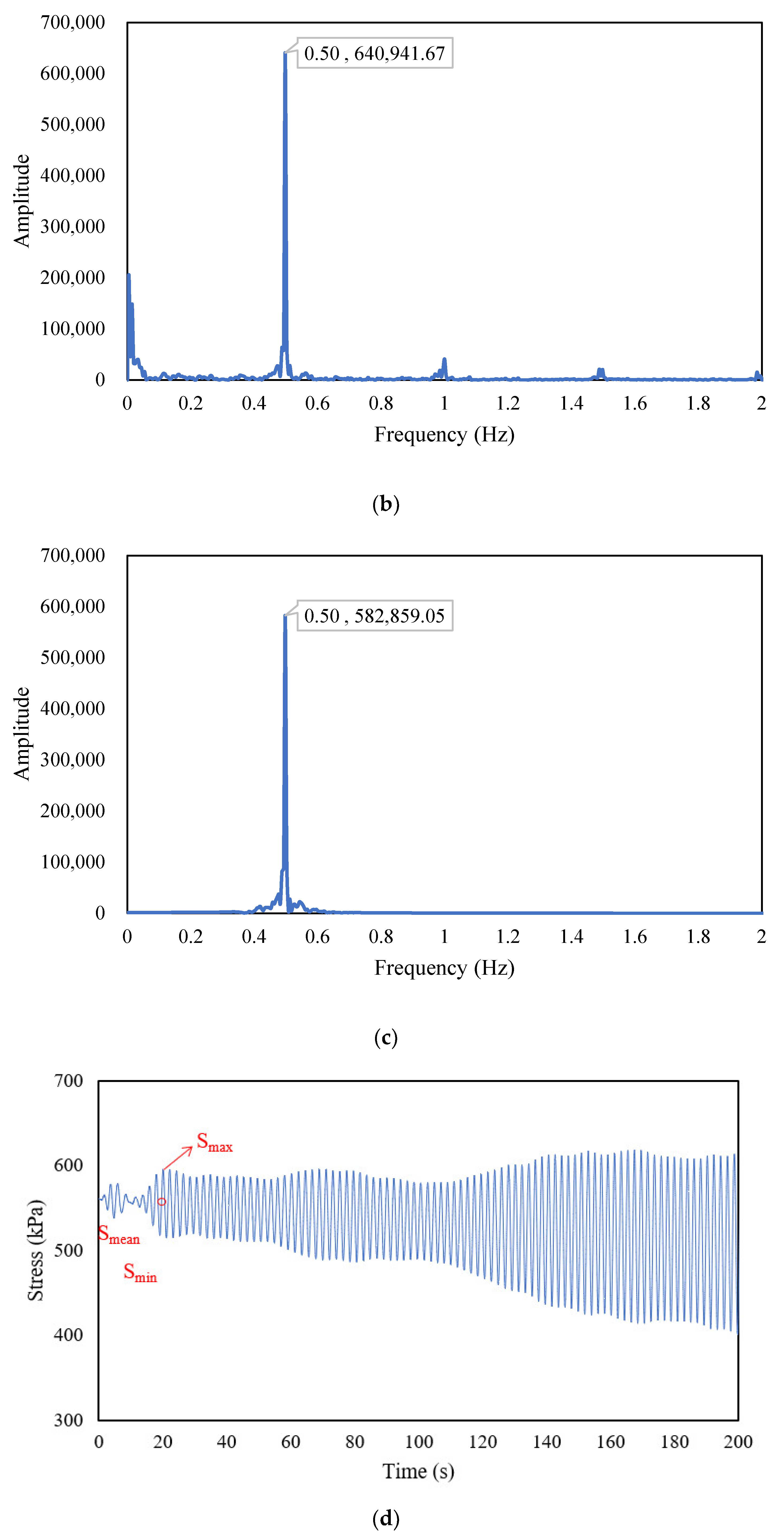

Figure 8.
Representative stress value in the SmartRock’s various embedded positions: (a) top, (b) center, and (c) bottom.
Figure 8.
Representative stress value in the SmartRock’s various embedded positions: (a) top, (b) center, and (c) bottom.
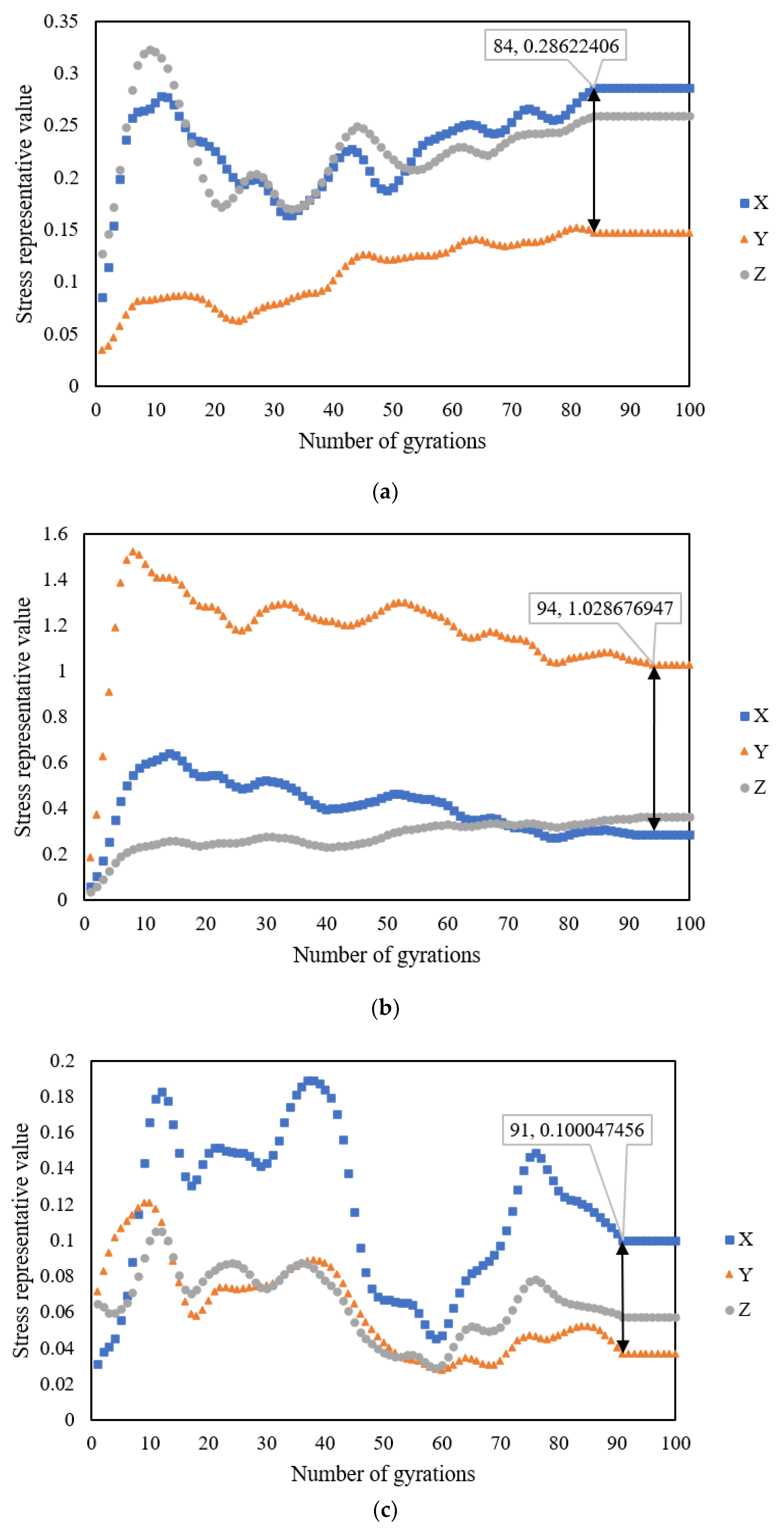
Figure 9.
Representative stress values at different compaction temperatures.
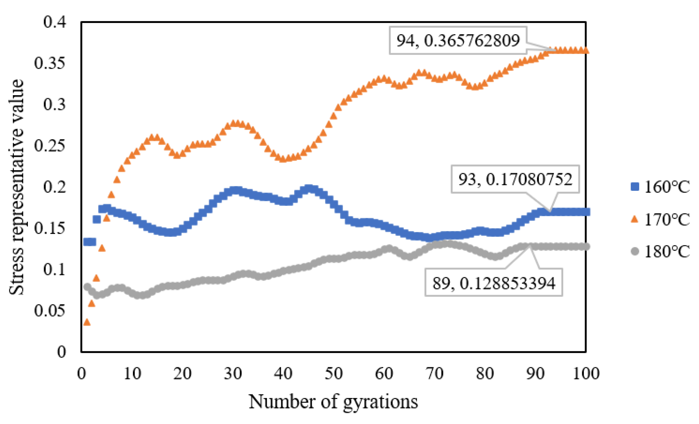
Figure 10.
Traditional locking points with different compaction temperatures.

Figure 11.
Locking point histogram.
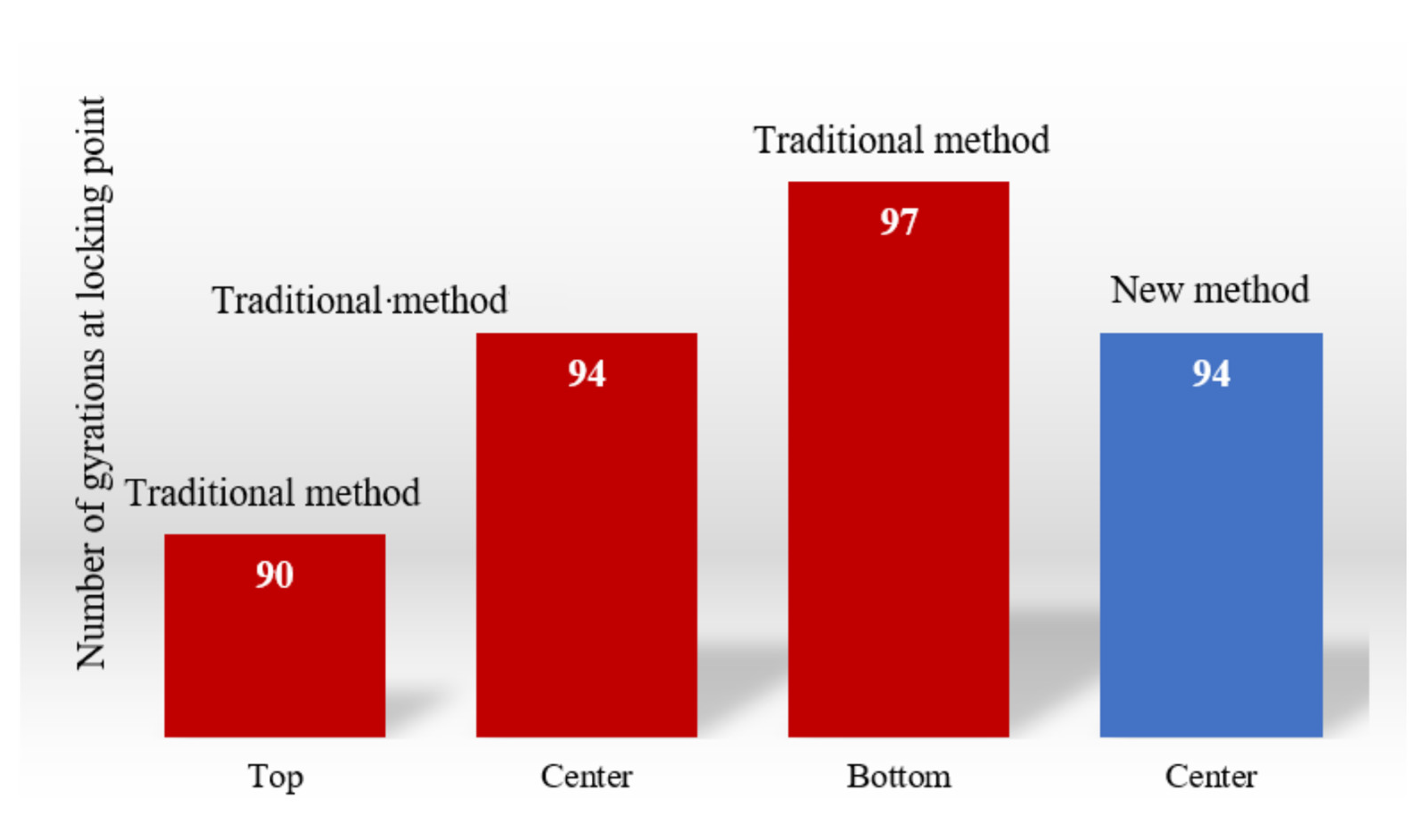
Figure 12.
Representative rotation angle value with different compaction temperatures: (a) 160 °C, (b) 170 °C, and (c) 180 °C.
Figure 12.
Representative rotation angle value with different compaction temperatures: (a) 160 °C, (b) 170 °C, and (c) 180 °C.


Figure 13.
Locking point comparison diagram.

Figure 14.
Representative acceleration value with different compaction temperatures: (a) 160 °C, (b) 170 °C, and (c) 180 °C.
Figure 14.
Representative acceleration value with different compaction temperatures: (a) 160 °C, (b) 170 °C, and (c) 180 °C.

Table 1.
Basic technical indicators of asphalt binder.
| Test Items | Measured Value | Requirement Value |
|---|---|---|
| Penetration (25 °C, 100 g, 5 s) (0.01 cm) | 48 | 30–50 |
| Ductility (5 cm/min, 5 °C) (cm) | 30 | ≥20 |
| Softening point at 5 °C | 81.5 | ≥70 |
| Density (25 °C) (g/cm3) | 1.031 | Measured value |
Table 2.
Basic technical indicators of coarse aggregates.
| Test Items | Measured Value | Requirement Value |
|---|---|---|
| Crushing value (%) | 13.5 | ≤22% |
| Flat, elongated particle content (%) | 8.5 | ≤12% |
| Particle size < 0.075 mm, content (%) | 0.5 | ≤1.0% |
| Adhesion | 5 | ≥5 |
Table 3.
Basic technical indicators of filler.
| Test Items | Measured Value | Requirement Value |
|---|---|---|
| Apparent density (g/cm3) | 2.705 | ≥2.50 |
| Water content (%) | 0.4 | ≤1 |
| Particle size < 0.6 mm, content (%) | 100 | 100 |
| Particle size < 0.15 mm, content (%) | 93.2 | 90~100 |
| Particle size < 0.075 mm, content (%) | 87.5 | 75~100 |
| Exterior | No clumps | No clumps |
| Hydrophilic coefficient | 0.81 | <1.0 |
Table 4.
Summary of asphalt mixture production ratio.
| Aggregate Grading (%) | Filler (%) | Asphalt Content (%) | Lignin Fiber (%) | Flame Retardant (%) | |||
|---|---|---|---|---|---|---|---|
| 0–3 | 3–5 | 5–10 | 10–15 | ||||
| 14 | 5 | 34 | 37 | 10 | 5.7 | 0.35 | 0.3 |
Table 5.
Temperature–stress calibration coefficients.
| NO. | ID | Type | Direction | a | b | c | U0 |
|---|---|---|---|---|---|---|---|
| 1 | 18:04:ED:6D:31:6E | High temperature resistant | front | −0.048 | 0.094 | −0.718 | 2.28 |
| left | −0.054 | 0.127 | −1.137 | 2.30 | |||
| bottom | −0.061 | 0.067 | −0.692 | 2.38 | |||
| 2 | 60:77:71:C6:71:45 | High temperature resistant | front | −0.044 | −0.065 | 0.042 | 2.32 |
| left | −0.050 | −0.065 | −0.084 | 1.86 | |||
| bottom | −0.053 | −0.022 | −0.396 | 2.04 | |||
| 3 | 60:77:71:C6:70:C4 | High temperature resistant | front | −0.053 | 0.092 | −0.661 | 2.30 |
| left | −0.067 | −0.021 | −0.416 | 2.44 | |||
| bottom | −0.052 | 0.003 | −0.424 | 2.00 |
Table 6.
Testing schedule.
| Asphalt Mixture | Sample Weight (kg) | SmartRock’s Embedded Position | Compaction Temperature (°C) | Sampling Frequency (ms) | Number of Gyrations | ||||
|---|---|---|---|---|---|---|---|---|---|
| 160 | 170 | 180 | Stress | Acceleration | Rotation Angle | ||||
| SMA 13 | 4.8 | top | × | √ | × | 10 | 10 | 60 | 100 |
| center | √ | √ | √ | ||||||
| bottom | × | √ | × | ||||||
√: specimen with the SmartRock embedded in the corresponding position compacted at the corresponding compaction temperature; ×: no specimen tested.
Publisher’s Note: MDPI stays neutral with regard to jurisdictional claims in published maps and institutional affiliations. |
© 2022 by the authors. Licensee MDPI, Basel, Switzerland. This article is an open access article distributed under the terms and conditions of the Creative Commons Attribution (CC BY) license (https://creativecommons.org/licenses/by/4.0/).
Share and Cite
MDPI and ACS Style
Cheng, Z.; Zhang, D.; Xie, S.; Polaczyk, P.A.; Wang, T. SmartRock-Based Research on Gyratory Locking Point for Stone Mastic Asphalt Mixture. Buildings 2022, 12, 97. https://doi.org/10.3390/buildings12020097
AMA Style
Cheng Z, Zhang D, Xie S, Polaczyk PA, Wang T. SmartRock-Based Research on Gyratory Locking Point for Stone Mastic Asphalt Mixture. Buildings. 2022; 12(2):97. https://doi.org/10.3390/buildings12020097
Chicago/Turabian StyleCheng, Zhiqiang, De Zhang, Shengjia Xie, Pawel Andrzej Polaczyk, and Tao Wang. 2022. "SmartRock-Based Research on Gyratory Locking Point for Stone Mastic Asphalt Mixture" Buildings 12, no. 2: 97. https://doi.org/10.3390/buildings12020097
Note that from the first issue of 2016, this journal uses article numbers instead of page numbers. See further details here.