
On the Seismic Behavior of Masonry Infilled Frame Structures


1
CONSTRUCT-LESE, Civil Engineering Department, 4200-001 Porto, Portugal
2
RISCO, Civil Engineering Department, University of Aveiro, 3810-193 Aveiro, Portugal
3
Computational Mechanics Laboratory, School of Pedagogical and Technological Education, 14121 Athens, Greece
*
Author to whom correspondence should be addressed.
Buildings 2022, 12(8), 1146; https://doi.org/10.3390/buildings12081146
Submission received: 27 June 2022
/
Revised: 18 July 2022
/
Accepted: 23 July 2022
/
Published: 1 August 2022
(This article belongs to the Section Building Structures)
Abstract
:Infilled frames are usually modelled in the context of global building analysis using simplified procedures without considering the aspects resulting from the interaction between the panel and the frame. Other aspects, such as adequate design of the floor beams and the beam-columns’ joints, and control of potential sliding shear failure of the columns, that significantly affect the structural response, are also typically not accounted for. In the present work it is intended to look over the literature to evaluate the state of the art regarding the lessons learn from recent earthquakes, the evolution of the structural codes considering the infill masonry panels, and how this influences the evolution of the numerical models and the experimental works to overcome the existent gaps.
1. Introduction
Accounting for seismic action in the design and construction of buildings has always been a delicate matter in engineering. The unpredictable nature of these natural phenomena, both in terms of occurrence and intensity, has always posed tough challenges. Earthquakes are the phenomena with the largest human and economic impact. Even though the larger are rare events, the scale of the devastation they can induce is so spread to cause decades of economic stagnation. Recently, several organizations have recognised the urgent need for consideration of seismic hazards and risks, emphasizing the importance of the work. A recent work developed particularly for Portugal by Silva (2013) points to this conclusion [1].
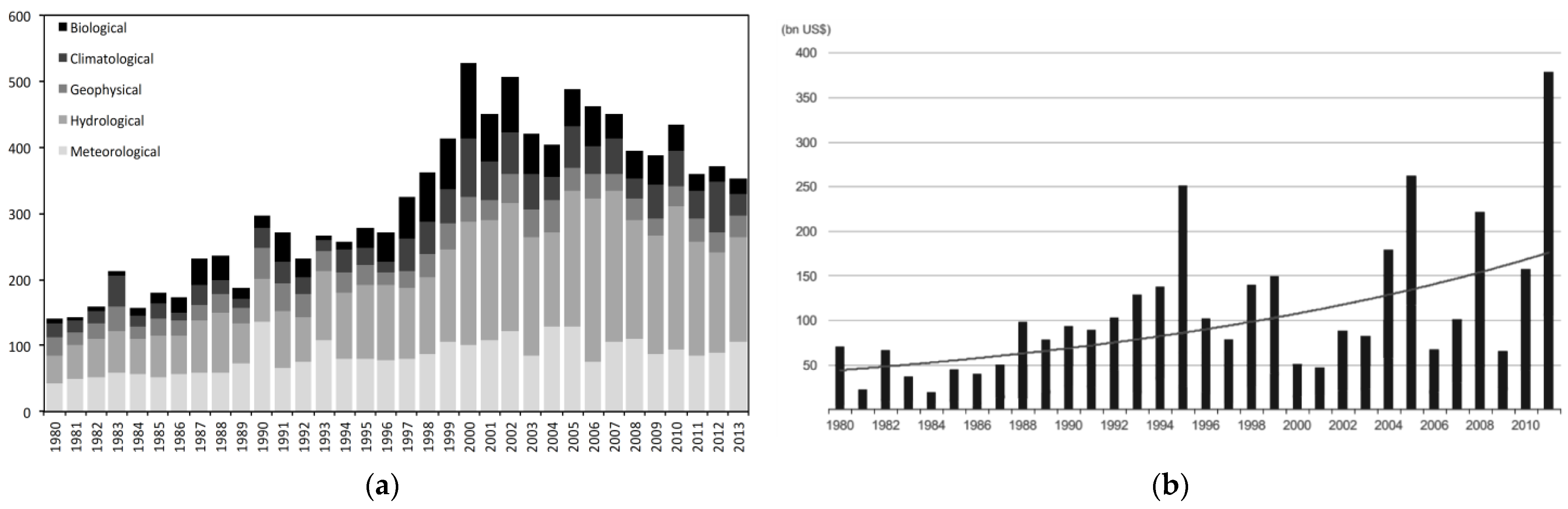
A similar conclusion can be extended to the rest of the world. Due to massive economical and human impact and the need to establish a better insight for seismic occurrences, this topic is extremely important to invest in. Although the number of geophysical events is not increasing (Figure 1a), the trends in economic losses are, and some of the biggest impacts are indeed a direct cause of earthquakes, as seen by the 1995 and 2011 peaks caused by Kobe and Japan-New Zealand earthquakes (Figure 1b).
This article intends to address complete research about the state-of-art on four main vectors regarding seismic vulnerability of reinforced concrete buildings: 1. International code recommendations, 2. Lessons learned from past earthquake performance, 3. Experimental work, and 4. Numerical modelling (divided into macro and micro modelling).
2. Behaviour of Masonry Infill Walls
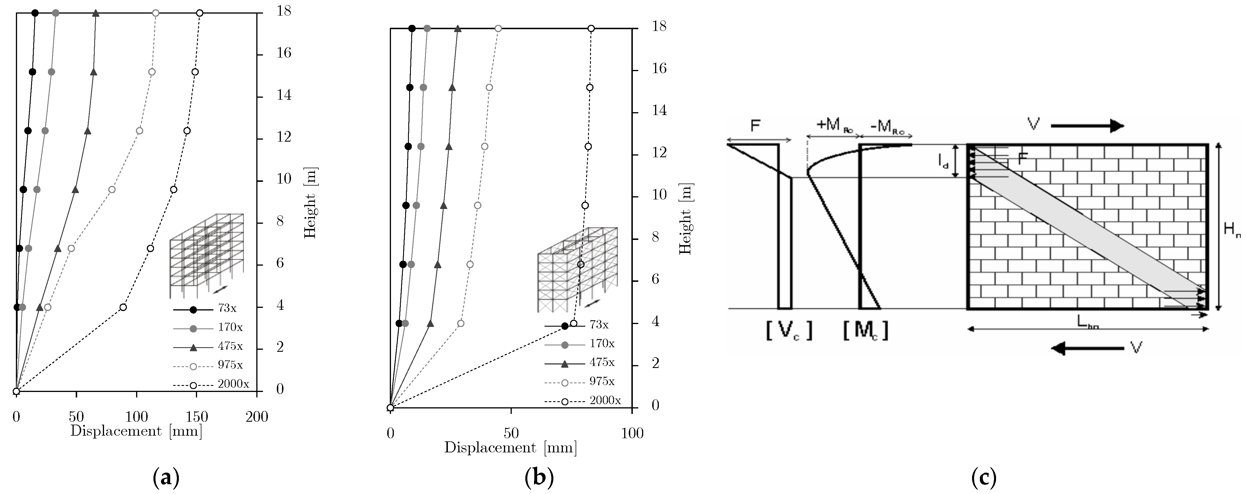
Masonry walls, when integrated within a reinforced concrete frame, have a different mechanical behavior compared to unconfined masonry walls. The lateral loading on the confined system creates mainly biaxial stresses with compression on the diagonal connecting opposite corners and tension on the perpendicular direction. The walls can also be subjected to high shear demands, failing along the mortar layers. However, the greater changes on the stress demands occur to the frame. The interaction between the two elements changes the behaviour of the assemblage completely. Figure 2a,b supports these remarks by showing the differences both on global and local levels. Analysing the displacements between a building with and without infill masonry walls, it is possible to assess that the bare-frame structure has higher deformations that are more distributed in height than the infilled frame. It shows that, for higher seismic demands, there is a tendency for concentration of deformations at specific levels, especially for the infilled frame. This occurrence leads to the formation of a soft-storey mechanism, a possible consequence intensified by the implementation of brittle masonry walls. Figure 2c shows the influence of the wall at the local level; the typical stress diagram of a bare frame is normally completely different from the presented here, demonstrating that ignoring masonry walls during the design of a structure can lead to errors on the expected stress resultants.
Infill walls are considered non-structural elements in RC structures because they are not intended to carry loads in static conditions. However, in case of higher deformations, lateral or vertical, these elements become active, change the response of the frame structure, and claim a structural influence, typically causing a reduction of the bending moments and an increase on the axial loads on the columns and beams. These aspects become even more important since the requirements for non-linear response evaluation of structures, according to new codes, are also higher. The walls increase the lateral strength of the frames locally, however globally they may reduce the base-shear strength of a structure due to failure on a certain level. At a global level, the infill walls can contribute to an increase of stiffness with the direct consequence of reducing the lateral displacements and can improve the dynamic behavior due to higher energy dissipation through friction on the structural interfaces between infill and frame.
The uncertainties related with the behavior of infilled frames are numerous. For medium-strong lateral loads, the frame tendency to deform creates a detachment between infill and frame. In this process, the contact length is mainly controlled by the relative stiffness between the involved elements. The bond strength between infill and frame on the mortar boundary layers is less significant for the global behavior of the system. Openings affect the behaviour of the infilled frame because the stiffness is not homogeneous which can result, for example, in short-column mechanisms, locally, or in undesirable loss of stiffness in a smaller region of the structure, globally. Hereupon it is noteworthy that infill walls with more than 50% of openings are usually ignored because the behaviour of the system is close to the bare frame. Moreover, as seen in Figure 2, infill walls completely change the load redistribution of the structure, creating, for example, local stresses concentrated near the corner region, which in turn can affect structural stability, causing another source of uncertainties.
The global influence of the infill walls is further discussed in Section 3 and Section 4, where global issues of relative stiffness and propagation of failure (in-plane and out-of-plane) are presented with reference to dangerous aspects of the structural response, such as torsional effects or soft-storey mechanisms.
Fardis (2009) assesses that the effect of masonry infills is generally beneficial for an infilled building without irregularities [4]. Table 1 summarises the advantages and disadvantages on the integration of infill masonry walls on RC buildings.
By neglecting the existence of the infill walls, a wrong lateral stiffness is indirectly assumed [5,6] for the structure in analysis, introducing potentially dangerous consequences such as unrealistic seismic design actions, prevention from accounting for torsional effects, formation of mechanisms, or local failures. It is worth noticing that although many issues were discussed about the behavior of infilled frames, the capacity of these infilled systems are stronger when compared to unreinforced masonry walls.
2.1. Failure Modes
Different failure modes may occur depending on the properties of the materials and the stress rate [7]. Several researchers have classified those modes in a slightly different way. The following list is a collection of some definitions; however, it is important to keep in mind that failure is usually attained through a combination of different modes and not due to a single reason. Some failure modes are identified as dominant nevertheless.
2.1.1. On Masonry Infill Wall
Many studies in the literature assess the various masonry infill failure modes. In some research papers [8,9,10,11], the failure modes are categorised into the following groups:
- Purely Flexural. It is identified as the case in which frame and infill wall cooperate as a unique element during a low loading phase. Since it does not reach a failure state from this behaviour, the mode is not considered as a primary failure mechanism.
- Sliding Shear. This failure occurs from the shear failure on the bed joint layer of the masonry infill wall. It is one of the most important failure modes, which decreases the stiffness of the panel and may create local deficiencies on the frame, but not an ultimate failure because the panel maintain some lateral strength capacity for the infilled frame. The mode occurs in masonry walls with a weak mortar joint and a strong frame.Multiple Sliding Shear. This mode is a special case of the previous one. While the single sliding shear is usually observed for an individual layer located near the middle of the panel, for the case of multiple sliding, the formations are distributed along the height of the panel, creating fewer local problems in the RC frame.
- Diagonal Compression. Occurs from the crushing of the infill. It may be located on the central region, and it is associated with slender infill walls and out-of-plane buckling.
- Corner Crushing. Crushing by compression located on one or more corners of the masonry panel, with probability of occurrence for weak infills within frames with strong members and weak joints.
- Diagonal Cracking. It is the formation of cracks along the infill compression strut, or also in the horizontal layer along the panel’s half height. It is common to occur together with sliding shear, corner crushing, or frame failure modes.
- Out-of-Plane. It is characterised by a more destructive and spectacular failure compared to in-plane failures. Seismic action does not occur perfectly aligned to the building directions. Therefore, the failure often occurs with a combination of in-plane and out-of-plane forces, with initial cracking caused by in-plane forces that weaken the wall substantially. Masonry walls, as infills for frame structures, due to the interaction with the bounding frame can develop out-of-plane resistance through the arching mechanism, which is mainly dependent on the slenderness of the wall, on the compressive strength of the masonry and on the support conditions. The risk for this type of failure can be greatly reduced by decreasing distances between supports, use of proper floor-to-ceiling supports, and attachment between walls and frames, however the available knowledge in this regard is still limited, especially for non-pure out-of-plane failure considering prior in-plane damage.
- Frame Failure. An obvious possibility for the failure is the formation of plastic hinges in the columns, or shear failure in the beam-column joints or columns. It can be caused by either a weak frame or weak joints with a strong infill. The failure induced by the infill walls may arise from a number of factors. The increase of stiffness and the forces introduced by the infills can elevate the axial stresses on columns (both in tension and compression). The diagonal truss of the infill creates a concentration region where the wall transfers some of the stress near the joints, resulting in increased shear stresses on both columns and the beams. In such a scenario the joints may fail, causing the failure of the system. The flexural and shear demands may increase even more if a short column is formed by an infill shear failure or by the existence of openings.
From this list, considering only in-plane demands, the most dominant types of failure are sliding shear on mortar layers, corner crushing, and cracking by diagonal tension. Table 2 correlates the in-plane failure modes with the infilled frame conditions. The blank spaces are too unpredictable to assume a tendency for the failure.
2.1.2. Structural Implications
The interaction of the non-structural elements with the structural elements, specifically infill masonry walls with columns, beams and their joints, has great structural implications. The combination of both responses during an earthquake increases the complexity of the system and may prove crucial for the structural safety.
This topic is furtherly discussed in Section 4, regarding lessons from previous earthquakes. However, some aspects are briefly introduced here. The infill walls, when distributed irregularly in plan, may introduce dangerous torsion effects on the buildings, which may lead to global collapse. On the other hand, when infills are distributed irregularly in elevation, soft-storey mechanisms (collapse/failure of a building’s level) can occur. Similar consequences can be inflicted if the stiffness of the infill walls is not properly balanced both in elevation and in plan, as a result of concentration of openings, thicker walls, etc., in a smaller region of the building. Weak infill walls, in-plane damage, and out-of-plane damage can induce the same vulnerable mechanisms of soft-storey and torsion. As a direct consequence on a local level, various adverse conditions may occur, such as column and joint shear failure due to strong infill or formation of short-column mechanism. At a global level, infill walls increase the stiffness of frames, which creates higher base-shear demands and also changes completely the redistributions of stresses on the structure.
3. Design Codes and Recommendations
This section is dedicated to the review of standards and codes, with special focus on the European recommendations and the influence of infill masonry walls in the behaviour of the structural reinforced concrete elements. Design and ductility requirements are firstly discussed before advancing to particularities about infill walls.
3.1. Concepts and Ductility
Eurocode 8 establishes two performance requirements, namely: (1) no-collapse, for which the designed structure, for seismic action, should not suffer any global or local collapse, and (2) damage limitation, in which a structure, subject to a seismic action lower than the design seismic action, should not exhibit severe levels of damage or suffer from a degradation of service [12]. They are related to the compliance criteria for safety level described by ultimate limit states (ULS) and damage limitation states (associated with serviceability limit states—SLS). These limits are established—in the case of ordinary structures—respectively for the following levels: (1) design seismic action (for local collapse prevention) with 10% probability of exceedance in 50 years, which corresponds to a mean return period of 475 years, and (2) damage limitation seismic (or serviceability) action with 10% probability of exceedance in 10 years which corresponds to a mean return period of 95 years.
The analysis methods that can be used are: (1) linear analysis with lateral force method for buildings meeting specific conditions, (2) linear analysis with modal response spectrum method applicable to all types of buildings, (3) non-linear static (pushover) analysis, and (4) non-linear time history (dynamic) analysis.
Eurocode 8 suggests, for framed RC structures, that all the joints should satisfy the condition where the sum of the moments of the columns (MRC) should be higher than the sum of the moments of the beam, according to:
to ensure that the plastic hinges are formed in the beams before columns. In terms of deformations, it is expected that the critical displacement associated with the collapse of a building is much higher, with this capacity restraint, due to better distribution of deformation demands to all storeys, instead of concentrating them in a specific location. This designing philosophy is indirectly related with the ductility classes and with the energy dissipation capacity of the structure, which should follow some rules for efficient performance. The code distinguishes three different ductility classes, identified as low (DCL), medium (DCM) and high (DCH) ductility levels. The low ductility class is only recommended for areas with low seismicity, following, for the most part, only provisions from the Eurocode 2. This type of structure should be prepared to sustain seismic action within elastic range. Outside the non-seismic areas, it is recommended to be designing with further provisions in order to increase the hysteretic capacity (non-linear behavior) to dissipate seismic energy of the buildings. Structures designed for ductility classes DCM and DCH should not have any type of brittle failure in any element.
3.2. Infilled Structures
There are three main philosophies for seismic design of infilled frames:
- Structural isolation by creating gaps between the masonry wall and the frame to allow free deformation by the frame. Some national codes adopting this philosophy are a Russian code (SNIP-II-7-81 1996 [13]), or an old New Zealand code (NZS1170.5 1995 [14], replaced later by the 2004 version [15]). It has some disadvantages regarding fire protection, thermal and sound insulation, or higher vulnerability for out-of-plane collapses during an earthquake. The advantages are mainly a better control of the structural behavior, in terms of stiffness, brittle failures, and undesirable effects created by irregular placement of infills.
- Use of the infill wall’s characteristics to reduce costs of construction and improve the comfort and seismic behavior of the buildings. Codes following this philosophy, such as the European one (CEN 2003 [12]), recommend some procedures to achieve realistic natural frequencies, stiffness and seismic design loads, to avoid irregularities, to account for openings, provisions of out-of-plane collapses, etc.
- Mandatory reinforcement of the masonry infill walls that is proposed from the International Building Code (ICC 2003 [16]). Infill masonry walls are permitted during design, but they must follow some stricter rules on their construction in order to improve their quality and control of the assumed conditions during the design of structures.
In Table 3 a summary of design provisions of several codes regarding infilled RC frames is presented. For this compilation reference is made to Chronopoulos and Chronopoulos (2012), Nazief (2014), and especially Kaushik et al. (2006) [17,18,19]. Most standards share similarities between each other.
FEMA (1997) specifies that masonry infill panels shall be represented as equivalent diagonal struts and may be placed concentrically across the diagonals, or eccentrically to directly evaluate the infill effects on the columns [20]. It specifies strength requirements for column members adjacent to infill panels. The shear force demand may be limited by the moment capacity of the column with reduced length. FEMA (2000) recommends various formulations for the analysis the masonry infills for both in-plane and out-of-plane directions [21].

| Country & References | D | Natural Period | Min. Force (%) | Irregularity | K | Drift | Infill | |||||
|---|---|---|---|---|---|---|---|---|---|---|---|---|
| Frame | Inf | Plan | Elev. | σi | Ki | O | OOP | |||||
| Greece (EAK 2000; nGCI 2012) [22,23] | - | - | - | - | - | - | - | - | - | - | - | - |
| USA (ICC 2003) [16] | N | X | N | N | N | N | X | N | N | N | N | N |
| USA (MSJC 2011) [24] | - | - | - | - | - | - | Y | - | Y | Y | Y | Y |
| India (IS1893-Part1 2002) [25] | Y | N | N | N | Y | X | N | N | N | N | N | |
| Israel (SI-413 1995) [26] | Y | 25 | N | Y | Y | 1.15 | N | Y | N | N | N | |
| Italy (NTC08 2008) [27] | - | - | - | - | - | - | - | - | - | - | - | - |
| Mexico (Mexican-Code 2004) [28] | - | - | - | - | - | - | - | - | Y | Y | - | Y |
| Nepal (NBC-105 1994; NBC-201 1994) [29,30] | Y | 25 | N | Y | Y | 2 | Y | Y | N | Y | Y | |
| New Zealand (NZS 2004) [15] | - | - | - | - | - | - | N | - | - | - | - | - |
| Philippines (NSCP 1992) [31] | Y | N | N | N | N | 1.5 | N | N | N | N | N | |
| Russia (SNIP-II-7-81 1996) [13] | - | - | - | - | - | - | - | - | - | - | - | - |
| Venezuela (COVENIN-2002 1988) [32] | Y | Rayleigh formula (*ray) | 25 | N | N | N | X | N | N | N | N | N |
| Only standard (FEMA 1998) [33] | Y | X | N | N | N | N | X | Y | Y | Y | Y | Y |
| Albania (KTP-N2-89 1989) [34] | Y | N | N | N | N | 1.2–1.5 | N | N | N | N | N | |
| Algeria (RPA 1988) [35] | Y | 25 | N | N | N | 1.42 | N | N | N | N | N | |
| Bulgaria (BGSC 1987) [36] | Y | X | N | N | N | Y | 1.5–3.0 | N | N | N | N | N |
| Canada (CSA-S304.1 2004) [37] | - | - | - | - | - | - | Y | - | Y | Y | N | - |
| China (GBJ-11 1989) [38] | Y | X | N | N | N | N | X | Y | N | N | N | N |
| Colombia (NSR 1998) [39] | Y | 25 | 100 | N | N | X | Y | N | N | N | N | |
| 25 | 100 | N | N | X | Y | N | N | N | N | |||
| Costa Rica (CFIA 1986) [40] | Y | N | N | Y | Y | X | Y | N | N | N | N | |
| Egypt (ECP 1988) [41] | Y | 25 | 100 | N | N | 2 | N | N | N | N | N | |
| Ethiopia (ESCP-1 1983) [42] | Y | 25 | 100 | N | N | 1.25Y | NNN | YNY | N | N | N | |
| Europe (CEN 2003) [12] | Y | 50–65 | N | Y | Y | 1.2 | Y | N | N | Y | Y | |
| France (AFPS 1990) [43] | Y | N | N | N | N | X | N | N | N | N | N | |
D (dynamic analysis for irregular buildings), K (ratio for design forces MI-RC), σi (strength of infill), Ki (stiffness of infill), O (considers openings of infill), Ct (correction factor for masonry infill), lwi (length of the wall i in the first storey), Ai (cross-section area of the wall), Ac (combined effective area of masonry infill in the first storey), h (height of the building), - (no information yet).
Eurocode 8 specifies that the period of the structure used to evaluate base-shear stress shall be the average between periods for the bare frame and for the elastic infilled frame [12]. Frame member actions are then determined by modelling the frame without the struts. Irregular infill arrangement (in plan and elevation) is addressed with important recommendations to avoid the formation of soft-storeys and torsion-effects. Moreover, designing techniques are suggested to account for irregularities, such as increase of accidental eccentricities and use of three-dimensional analysis. Regarding irregularities in elevation, if a refined model is not used, the code suggests the computation of a magnification factor to increase the seismic actions on columns:
where VRW is total reduction in lateral resistance of infills compared to the storey above, VEd is the seismic shear forces on all vertical members in the examined storey, and q the behaviour factor dependent on the ductility class of the structure. If the value η is less than 1.1, it is not necessary to increase the designing forces.
In terms of lateral load shared between infill walls and the frame, CEN (2003) does not make a reference to the infill walls, considering only that the frame system should resist totally the vertical loads, and possess a 65% base-shear capacity—50% at minimum for other types of structure—of the total lateral loading on the building [12]. For the serviceability limit state, it is recommended to control the lateral deformation between storeys (drifts, dr). For buildings with brittle non-structural elements, it should be limited to 0.005 h/μ. For buildings with ductile non-structural elements the drift is limited to 0.0075 h/μ, or 0.010 h/μ if the building does not have non-structural elements. (h is the height of the storey, and μ is the reduction coefficient ranging from 0.4 to 0.5, depending on the importance class). Due to the nature of the infill masonry walls, which indeed are non-structural and brittle elements, the limit to be used is 0.005 h/μ.
The second generation of the Eurocodes is now in discussion and several changes are expected in regard to the infill masonry walls. For example, the masonry infills should be classified as interacting or non-interacting, and this fact will change the design of the RC structure. In the non-interacting infill walls the contribution for the lateral (in-plane) stiffness and resistance may be neglected, and this fact is much dependent on the bounding connection between the infill wall and the frame, assuring the proper out-of-plane capacity. If the building has interacting infills, the design may continue to assume the bare frame only, especially in the case of regular distributions of the infill masonry panels with simplified approach; however, the new generation of the Eurocode 8 may give direct recommendations for the explicit consideration of the infill masonry walls in the linear and non-linear design of RC structures.
Other codes require full resistance of the lateral loading from the infill walls, which can only be achieved by specific measures so that the walls are structurally connected to the surrounding RC structure. Nepal’s code (NBC-105, 1994) has considerations for masonry infills with openings, considering only those walls with more than 90% of the gross panel area [29]. It also specifies three areas for openings, (1) restricted zone (areas next to the corners with 1/3 of height and width), (2) significant opening (middle area), and non-significant area (next to columns and beams). Inside the significant area it is necessary to strengthen the wall with strategies of RC tie-bands.
4. Lessons from Earthquakes
This section is dedicated to observation of damages and lessons earned from previous earthquakes. Section 4.1 focuses on the vulnerability of RC buildings for recent events close to Europe, with a special interest on the interaction and failure of infill walls. Next, in Section 4.2, a collection of studies on other earthquake events around the world is presented.
4.1. Recent Earthquakes in Europe
The impact of natural disasters is rising every year. Databases such as EM-DAT [44] and Munich-Re [2] corroborate these trends, both in terms of number of events and of human and economic losses [1]. While the number of earthquake occurrences worldwide is not so profound, when compared to other types of natural or man-made extreme events, the associated global costs and impact is extremely high.
Herein, the lessons learned from the observations of damages in reinforced concrete building structures affected by recent earthquakes in Europe are discussed. The discussion and analysis are focused on both the structural (columns, beams, joints, etc.) and non-structural (masonry infill walls, parapets, etc.) elements, in order to achieve a thorough understanding of the most common errors and deficiencies (during the design or construction phase) on building systems that can lead to severe consequences when exposed to earthquake demands.
This section is focused on the following three earthquakes (listed in Table 4): the first occurred in Italy, region of Abruzzo, L’Aquila, on the 6 April 2009 and reached a magnitude of 6.3, killed 308, left around 65,000 homeless, and the economic losses were up to USD 10,000 million; the second one occurred in Spain, Lorca, on the 11 May 2011, with a magnitude of 5.1, nine fatalities, left around 5000 homeless and economic losses estimated around USD 99 million and the last one, again in Italy, in the region of Emilia-Romagna, on May 2012, struck with two main shocks with magnitudes of 6.1 and 5.8, causing 26 fatalities, 43,000 homeless, and economic losses of USD 13,000 million [45,46]. Reference is made in Rodrigues et al. (2010) and Vicente et al. (2010) for Abbruzo’s earthquake and in Romão (2013) for Lorca’s earthquake [47,48,49]. Even more recent earthquakes such as in Nepal in 2015 [50], Central Italy in 2016 [51], Northeastern Aegean, Greece in 2017 [52,53,54], Albania in 2019 [55,56] or in Zagreb in 2020 [57,58] show similar problem in RC infilled masonry buildings.
Observed Damages
This is an outline of the observed deficiencies in RC buildings that led to severe damages, throughout the above three seismic events: (i) Stirrups and hoops, (ii) Detailing; (iii) Inadequate capacity and failure; (iv) Inadequate shear capacity of the joints, (v) Influence of the infill masonry on the seismic response of the structures; (vi) Structural irregularities (vii) Short-column mechanism; (viii) Strong-beam weak-column mechanism; (ix) Secondary elements and surroundings, (x) Non-structural elements. From the collected observations on the RC buildings from these recent earthquakes it is possible to summarise the most important lessons:
- RC buildings with 3 up to 6 storeys, with masonry infill walls, exhibited the larger damages.
- Ground storeys without wall infills, used for commerce/services, can be decisive for the building behaviour and performance.
- Higher level of damage occurred at the lower storeys in both structural and non-structural elements.
- Poor reinforcement detailing in the beam-column joints resulted in the formation of plastic hinges in the columns prior to beams.
- Several collapses and buildings marked for demolition were due to shear failure of the columns, designed as slender columns.
- Non-structural elements with very poor performance caused major economic losses and some deaths.
- A great number of failures of masonry infill walls (due to in-plane actions) was recorded and detachments of the exterior panels in façade’s masonry walls, as well.
Although the damages are related to all sorts of different deficiencies, most conclusions point to the influence of the infills and reinforcement detailing [48,49,59]:
- Most damages on the buildings come from non-structural elements, such as infill walls.
- Building collapses occurred from irregularities in plan or in elevation from both structural and/or non-structural elements.
- Structural damages are mainly present in columns, walls and beam-column joints due to insufficient shear capacity.
In order to reduce the vulnerability of existing and new buildings, masonry infill walls’ influence cannot be ignored in structural design; particular attention should be given to the stiffness differences between the first and upper storeys (storey height, dimensions and position of openings, distribution of masonry infill walls); and reinforcement detailing should be enforced, particularly on beam-column joints, in order to provide the required anchorage of the longitudinal bars.
4.2. Seismic Performance
A brief list of earthquakes, organised by location and time, is available in Table 4, with information regarding magnitude, and economical and human impacts. The presented earthquakes were examined for the seismic behaviour of RC buildings.
Hamburger and Meyer (2006) studied the San Francisco, USA earthquake, in 1906, based on old damage-analysis reports [62]. The referred beliefs that infilled steel-frame structures had a good performance, with increased strength, stiffness and ductility, were questioned because they were dependent on the limited knowledge level of that period, since the infill wall’s influence started to be studied years later.
Tiedemann (1980), for the Guatemala City, Guatemala earthquake, concluded that 80% of the total costs associated with damage in buildings were due to the non-structural elements (namely, infill walls, supply systems, and other equipment) [63].
On the earthquake of Northridge, USA in 1994 [64], 16 of the 58 fatalities were due to collapses of buildings with a soft lower storey, characterised by the absence of strength degradation of infill masonry walls.
For Kobe, Japan in 1995 [65], the buildings built after the new Japanese seismic code of 1981 performed well, excluding buildings with a soft ground storey. The main issues on those RC buildings were soft-storey mechanisms leading to severe damage or collapse, torsion effects, insufficient detailing at the shear reinforcement, short-column mechanism, damages on infill walls, and damages on the separation joints between non-structural and structural elements.
In Dinar, Turkey 1995 [66], 40% of RC buildings collapsed or had severe damages. The main vulnerabilities were column slenderness, bad detailing on transversal reinforcement, soft-storey, bad quality of materials, and high levels of damage on infill walls.
The studies for the earthquake of Jabalpur, India in 1997 showed that the majority of buildings without infill walls at the base-storey suffered the most from the earthquake, and that—in general—buildings with infill walls had a satisfactory performance [67]. Moreover, the impact of infill walls placement was observed.
The major damages verified after the earthquake of Adana-Ceyhan, Turkey, 1998 [68], occurred on non-structural elements, both by in-plane and out-of-plane failure. The buildings designed with the new seismic philosophies still did not perform satisfactorily, showing vulnerabilities of weak-column-strong-beam mechanism, irregularities in plan, inadequate shear reinforcement, and other construction deficiencies.
The observed issues on Kocaeli, Turkey’s earthquake of 1999 [69,70], were soil liquefaction, weak storeys, short columns, inadequate column confinement, bad detailing, and damages on infill walls at the lower storeys. Some collapses were initiated with the failure of infills on a specific level. Different behaviours were observed in this earthquake, since some buildings showed a large level of damages while others nearby did not. Since those incidents involved buildings with similar design philosophies, the damages could be correlated to the influence of infill walls’ placement, quality of the concrete, bad detailing, or construction quality.
In Greece, until 1999, buildings were not designed with ductility requirements. When the Athens, Greece earthquake occurred on 7 September 1999, issues related to bad quality of materials, inadequate reinforcement, bad connection quality in joints, existence of short columns and weak storeys were observed [71].
On Chi-Chi’s earthquake, Taiwan in 1999 [72,73,74], the main issues observed were weak storeys, short columns, the weak-column-strong-beam mechanism, and low ductility on columns due to detailing.
For the earthquake of Gujarat, India in 2001 [75,76,77], the main damages were due to weak storeys, insufficient ductility because of bad detailing and quality of materials applied on the structural elements. Irregularities in plan and in elevation increased the observed damages. The infill walls were identified as inducing issues of soft storeys, the short-column mechanism, and torsion effects. Favourable aspects were also mentioned related with avoidance of collapse on some buildings with bad quality.
In Bingöl, Turkey 2003 [78,79,80], the main issues were related with discontinuities on vertical elements, weak storey, short columns, long cantilevers, irregularities in plan and elevation, and bad quality of detailing and execution.
For Sumatra, Indonesia, 2004 [81,82,83,84], the main issues were related with soft storeys, short columns, detailing on column-beam joints, and interaction between infill walls and structure.
On the earthquake of Sichuan, China 2008 [85,86], the main issues were the collapse of columns because of shear failure and excessive deformations, and also soft-storey mechanisms. The infill walls were considered to have a strong influence on the observed damages.
Haiti’s earthquake of 2010 exposed bad construction quality and inadequate detailing. It was also verified that masonry walls, built with concrete units, performed badly [87,88]. The earthquake of Maule, Chile of 2010 had a long duration, between 2 and 5 min, and also high vertical accelerations. However, the design of RC buildings in Chile is very advanced and—in general—buildings had a good response. Some issues were identified regarding soft-storey mechanisms and horizontal cracks on the RC walls, instead of the usual diagonal [89]. The behaviour of the buildings for the earthquake of Christchurch, New Zealand in 2011 was—in general—satisfactory. The main issues were related with a pounding phenomenon between adjacent buildings [90,91]. For Tohoku, Japan’s earthquake in 2011 the identified damages were highly related with the tsunami and liquefaction of the soils [92].
5. Experimental Work
Results from experiments are necessary for the calibration of the numerical models and retrofitting analytical formulations. For that purpose, extensive works have been performed and are included in this state-of-the-art. Some of those experiments were focused on different purposes, such as in-plane strength, out-of-plane strength, deformation, energy dissipation, damage types, influence of openings, through monotonic loading, cyclic loading, or shake table tests.
The amount of different testing programmes, and variables in them, makes the thematic grouping of experimental works virtually impossible. For example, works could be organised in terms of type of loading that can be monotonic, cyclic, pseudo-dynamic or in a shaking table, direction of the test that can be purely in-plane, purely out-of-plane or combined, or the materials properties of the frame and/or infill wall that can be of reinforced concrete, steel, concrete blocks, or brick masonry. Therefore, the experimental works are organised by their date, accompanied with a brief description, and some of the most important general conclusions from each work. By the nature of the information contained in this section, the descriptions follow a common pattern for easier assessment from the reader. All information is planned to be available on a friendlier platform and with higher level of completeness, such as a collaborative database.
A more exhaustive list of experimental work is presented at last on Table 5.
Jorquera (1964) tested full-scale RC frame infilled with brick masonry (typology used in Chile), single bay (2.4 m) and single storey (2.4 m), for in-plane monotonic horizontal loading [101]. The campaign was dedicated to study the influence of different types of bricks. Some of the conclusions were: (1) resistance of infilled frames exceeded 12.5 to 22.5 times that of bare frames, (2) the properties of the infill materials greatly influenced the resistance of the system.
Stafford-Smith (1968) tested three reduced-scale steel frames (covered or not with concrete) infilled with concrete walls or brick masonry, single bay, and single storey, for in-plane monotonic horizontal loading [106]. Stafford-Smith (1968) evaluated walls for different aspect ratios (h/l of 1.0, 2/3 and 1/2) with distributed vertical loading [106]. Some of the conclusions were: (1) concrete walls introduced higher stiffness on the system than brick masonry walls, (2) brick masonry walls have higher capacity to deform without such an intense decrease of loading capacity, as verified for concrete walls, (3) low vertical loadings had little to no influence on the failure mechanism of the wall, (4) vertical loadings lower than half of their capacity lead to an increase of lateral ultimate capacity, and (5) vertical loadings bigger than half of their capacity lead to a decrease of lateral ultimate capacity by compressive crushing failure modes.
Trigo (1968) tested reduced-scale RC frames infilled with concrete walls and brick masonry walls, single bay and single storey (h/l of 1.0), for in-plane monotonic horizontal loading [107]. Different walls and properties were tested, for different ranges of vertical loadings on the columns. Some of the conclusions were: (1) vertical loading led to reduction of ductility on the concrete walls, and (2) vertical loadings led to an increase of ductility on the brick masonry walls.
Fiorato et al. (1970) tested 1/8-scaled RC frames with brick masonry walls, single bay, and single storey [110]. The testing was performed in-plane with both monotonic and cyclic loadings. The specimens had varying frame and wall dimensions, quality of materials, ranges of loading (both horizontal and vertical), and also the influence of openings was studied. Some of the conclusions were: (1) the horizontal shear failure on the infill leads to a short-column mechanism, enabling the development of plastic hinges or shear failures on columns, (2) infills increase the ultimate loading capacity of the frame, (3) infills reduced the ductility of the system, (4) vertical loading increases both resistance and stiffness of the system, (5) existence of openings reduces both stiffness and resistance, which are not directly proportional to the area of the openings.
Mallick and Garg (1971) tested reduced-scaled steel frames with concrete walls, single bay and single storey (h/l of 1.0), in-plane for monotonic loading [114]. Aspects such as influence of openings and metallic connections between frame and infill were studied. Some of the conclusions were: (1) the connectors increased both stiffness and loading capacity of the system, (2) the metallic connections, by limiting the separation between frame and wall, helped the system to behave as one body, achieving higher deformations, (3) presence of openings decreased the stiffness of the system, even more if placed next to the wall corners.
Dawson (1972) and Dawson and Ward (1974) tested six reduced-scale steel frames with concrete walls, a single bay, and four storeys (h/l of 6/7), in-plane for monotonic loading [116,117]. The testing focused on the interface (bonding) between frame and infill, for different levels of quality and when totally absent. Some of the conclusions were: (1) systems with bad quality of bonding between infill and frame presented similar initial stiffness as bare frames, (2) for higher frame deformations, when the full contact between infill and frame is achieved, the stiffness level increased substantially.
Leuchars and Scrivener (1976) performed three, half-scale tests on RC frames, in single bay and single storey (h/l of 5/8), for in-plane cyclic loading [119]. One was bare frame, another one was infilled with reinforced brick masonry walls on two directions and vertical bars connected to the beam, and the third specimen was built with the concrete filling the hollows of the bricks. The study was dedicated to the influence of reinforcement on the walls. It was concluded that the resistance of the infilled frames were 3.5 times higher than the bare frame.
Klingner and Bertero (1976) and Klingner and Bertero (1978) performed five tests with 1/2-scale RC frames infilled with brick masonry and concrete blocks, a single bay, and three storey (h/l of 2/5), for in-plane cyclic loading [120,121]. A test with a bare frame and another two with reinforced (in two directions, with steel bars) masonry walls were performed. Then, the frames of the two infilled specimens were used again to be tested with the concrete blocks. The experimental campaign was dedicated to the influence of different types of the walls and to assess the designing of high-dissipation systems against seismic actions. Some of the conclusions were: (1) the initial stiffness of the infilled specimens was up to five times higher than the bare frame, (2) the authors assessed that the increase of dissipation of energy capacity and of resistance—introduced by the reinforced masonry—have stronger benefits than the undesirable secondary effects caused by the increase of seismic demands due to the stiffness of the system.
Jurina (1977) performed five tests with half-scaled RC frames infilled with pre-made reinforced walls in brick masonry, in single bay and single storey (h/l of 2/3), for in-plane cyclic loading [122]. The testing studied different infill reinforcements and connections, and infilled frames designed for strong seismic actions. The infilling typologies were: simple masonry wall, reinforced masonry on both directions and connected vertically to the beam, pre-made reinforced masonry walls connected to the beam, and finally a specimen built with stepped masonry on the edges with the column’s being constructed after the wall, for better bonding. No vertical loading was imposed. Some of the conclusions were: (1) the stiffness of the system was increased for infilled specimens, (2) the loading capacity increased from 3.1 to 5.4 times for infilled frames compared to bare frames, (3) the initial stiffness was 4 (infilling of pre-made masonry) to 30 (infilling with reinforced masonry) times higher compared to bare frames, (4) the reinforced masonry wall system had the highest ultimate loading capacity, and (5) the stepped masonry wall had a similar loading capacity to the simple masonry wall.
Liauw (1980) and Liauw and Kwan (1984) tested three reduced-scaled steel frames with concrete walls, a single bay, and four storeys (h/l of 1/2 to 1/3), for in-plane monotonic loading [125,126]. The experiments were dedicated to the connections between frame and infill. Some of the conclusions were: (1) the connectors increased both stiffness and loading capacity of the system, (2) the metallic connections, by limiting the separation between frame and wall, helped the system to behave as one body achieving higher deformations.
Parducci and Mezzi (1980) performed eight tests with 2/3-scaled RC frames with and without brick masonry walls, in single bay and single storey (h/l of 4/7), under in-plane cyclic loading [127]. The type of bricks, amount of reinforcement on columns, and different bonds between columns and walls were investigated. Other aspects involved half of the specimens being built with a 40 cm height of the top beam, and the other half with 10 cm of height in order to simulate the infill behaviour within a slab confinement. Some of the conclusions were: (1) higher resistance of the infilled systems from two to three times larger, compared to the bare frame, (2) a stronger resistance degradation of the system with infilling, was verified, occurring specifically to the concrete elements that may have been connected to misplaced hoop reinforcement on the columns.
Brokken and Bertero (1981) and Bertero and Brokken (1983) performed 18 tests with 1/3-scaled RC frames infilled with brick masonry and concrete blocks, single bay, and three storeys (h/l of 2/5), under in-plane cyclic loading [129,130]. The tests studied the system behaviour for different types of walls and placements (full height or absent from a storey), following the work of Klingner and Bertero (1976) [120]. The walls were reinforced in both directions, about 0.6% of the wall’s area. Some of the conclusions were: (1) the resistance of the systems without walls on the first storey were from 2.2 to 7.9 times higher than the bare frame system, (2) the resistance of the systems infilled with concrete walls on all storeys were from 1.7 to 11.7 times higher than the bare frame system, (3) it was assessed that the infill of frames is a good retrofitting measure and that the concrete blocks are the most suitable for it.
Žarnić and Tomazevic (1985) performed eight tests with 1/3-scaled RC frames infilled with or without concrete block walls, in single bay and single storey (h/l of 5/8), under in-plane cyclic loading [132]. Reinforcements on the walls and different connections, some to the columns and another to the beam, were examined. No vertical loading was imposed to the models, and the maximum drift was limited to 5%. Some of the conclusions were: (1) the construction process did not have a major influence on the testing campaign, (2) the first cracks were formed on the horizontal and vertical interfaces between the wall and frame to a drift of 0.14%, (3) the initial stiffness was increased six times when the frames were infilled, (4) ultimate loading capacity was increased by 40% for infilled frames, (5) the quality of the bonding between wall and frame may have affected the capacity of the system, (6) the horizontal reinforcement of the wall and its connections to the frame had low influence on the response of the system, and (7) a strength degradation of 25% for two consecutive cycles with the same deformation was identified.
Stylianidis (1988) performed 18 tests with 1/3-scaled RC frames infilled with brick masonry walls, in single bay and single storey (h/l of 6/10), under in-plane cyclic loading [142]. Testing variables included the existence of infill, aspects such as loading on columns, connection between components, use of different mortars, and the influence of one RC lintel in the middle of wall. The maximum imposed drifts were 2.4% for infilled models and 3% for the rest. Some of the conclusions were: (1) the failure mode of the frames was similar with or without infill walls, except in some cases where a plastic hinge was formed at middle height of the columns, (2) the infilled frames showed a much higher pinching effect compared to the bare frame, (3) the infilled systems were 4.5 (no vertical loading) and 5.3 (with vertical loading) stiffer than the bare frame, and 1.8 and 1.6 for the loading capacity, respectively, to the same conditions, (4) the ductility decreased with the infilling, (5) the ductility increased slightly when vertical loading was applied on the columns, (6) a strength degradation of 15% was achieved for two consecutive cycles with the same deformation, (7) vertical loading on columns increased resistance, initial stiffness and capacity to dissipate energy, but reduced ductility slightly, (8) a good quality of interface between infill and frame increased resistance and energy dissipation but did not affect the ductility, (9) mortars with high compressive strength increased slightly the resistance of the wall but did not affect the ductility, and (10) the lintel reduced the resistance, initial stiffness, and energy dissipation for low drift levels.
Govindan et al. (1986) and Govindan et al. (1986) performed four tests with 1/4-scaled RC frames infilled with brick masonry walls, in single bay and seven storeys (h/l of 3/4 and 6/10), under in-plane cyclic loading [140,141]. The loading was imposed at the third, fifth, and seventh storey levels. No vertical loadings were applied. The main purpose of the testing was to compare the behaviour between bare frame structure and infilled structure. Some of the conclusions were: (1) the ultimate capacity of infilled frames were two times higher than the bare frame, (2) the initial stiffness was five times higher with infills, (3) the energy dissipation capacity was increased with infills, (4) the ductility was reduced with the infills.
Dawe and Seah (1989) tested 28 full-scale in a steel framed single-storey (2.8 m) and single bay (3.6 m) specimens infilled with hollow concrete blocks (200 mm × 200 mm × 400 mm), for a monotonic in-plane and horizontal loading [145]. The tests investigated the frame-wall boundary conditions, opening sizes, joint reinforcement, strength of the diagonal strut, bonding between beam and infill, and frame stiffness. Some of the conclusions were: (1) absence of mortar between infill and frame affect slightly the initial stiffness of the system; however, the ultimate load was reduced by 20%, (2) the cracking pattern was modified with the presence of ties, (3) the presence of gaps, or no bond, between top-beam and infill caused a reduction of the ultimate load by 50%, (4) poor mortar quality between these elements achieved similar reduction of 50%, (5) reinforcement of the steel joints had little to no impact on the initial stiffness and capacity, (6) in a frame with hinges it was verified that an early detachment of infill and the frame led to a reduction by 50% of the ultimate load, and (7) reinforcement of the diagonal strut led to an increase of the initial stiffness and ultimate capacity by 76% and 31%, respectively. Regarding infill openings: (1) central door openings led to a reduction by 54% of the initial stiffness and 40% of carrying capacity, (2) openings located away from the loading side led to a reduction of the same attributes by 32% and 34%, respectively, while for openings near the loading region the reductions were 53% and 56%, respectively.
Dawe and Seah (1989b) tested nine full scale steel frames infilled with concrete blocks, single bay (3.6 m), and single storey (2.8 m), against out-of-plane forces [146]. The loading on the wall was transferred with a system of airbags against a reaction frame, uniformly inflating to impose a displacement. The objective was to study the horizontal connections with reinforcement, the mortar interface of infill-frame, the influence of the wall’s thickness, openings, and other aspects. Some of the conclusions were: (1) the interface’s reinforcement provided higher out-of-plane ductility for the system, (2) interface reinforcement sustained increased out-of-plane loading before first crack, (3) higher thickness prevented the out-of-plane arch mechanism, resulting in higher collapse loads, and (4) the opening did not reduce significantly the out-of-plane capacity.
Dawe et al. (1989) performed 10 dynamic tests on 1/3-scaled steel frames, infilled with brick masonry, in a shake-table [147]. Flexible joints, rigid joints, and flexible joints without infills were tested. Some of the conclusions were: (1) on the rigid joint’s frame, the infill detached from the frame and diagonal cracking was formed, and (2) stiffness of the systems was increased for infilled frames.
Liauw and Kwan (1992) tested two 1/3-scaled tri-dimensional RC models in a shake-table [153]. The models featured four storeys with one bay in each direction. One model was infilled with brick masonry walls and another model with concrete walls, both in only one direction. The other direction was fixed with a set of metallic struts. Each level featured a concrete slab with 40 cm of thickness. Some of the conclusions were: (1) no significant differences in terms of resistance were found between the two models, (2) the possibility for out-of-plane collapse was recognised, especially under real seismic actions, for which the direction of seismic accelerations is not controlled.
Mehrabi et al. (1994) performed 14 tests with half-scaled RC frames infilled with hollow brick, solid brick masonry and solid concrete blocks, in single bay and single storey (h/l of 2/3), for in-plane cyclic loading [157]. Testing was performed for single-leaf and double-leaf walls on brick masonry and concrete block wall. Some of the conclusions were: (1) the resistance was lower under cyclic loading compared to monotonic loading, (2) the strength degradation of the system was faster under the cyclic loading compared to monotonic loading, (3) high vertical loading increased substantially the ultimate loading capacity of the system, (4) the resistance was increased by 68% and 85%, respectively, for strong and for weak frames, with double-leaf infills, and (5) it was assessed that the behaviour of the system with infills was better overall.
Angel et al. (1994) tested eight full scale RC frames infilled with concrete blocks and with brick masonry walls [156]. The interaction between in-plane and out-of-plane behaviours was tested. The systems were damaged in-plane, prior to application of out-of-plane loading. The initial damage was inflicted by imposing twice the level of lateral displacement that provoked the first crack on the infill. The out-of-plane forces were applied with air-bag systems following monotonic loading schemes. Some of the conclusions were: (1) the stiffness (in-plane) was significantly reduced after the first crack, (2) the shear strength of the infill was greatly affected by the mortar, (3) the stiffness (in-plane) of the system was proportional to the masonry’s compressive strength, (4) the cracking pattern for out-of-plane was a diagonal with horizontal central lines connecting the diagonals, (5) the out-of-plane strength was affected by the thickness of the wall and by the compressive strength of the masonry, (6) in-plane loading increased the out-of-plane stiffness.
Mehrabi et al. (1996) tested 12 half-scaled RC framed single storey and single bay specimens, infilled with solid and hollow concrete blocks (simulating strong and weak infills, respectively) under an in-plane static-monotonic procedure [161]. Two different schemes were tested: one designed for strong lateral forces (earthquake) and another for wind loads, ignoring the contribution of the masonry infill walls. Openings and gaps on the infill walls were not tested. Some of the conclusions were: (1) lower aspect ratios of infill walls (h/l) showed stronger lateral loading than higher aspect ratios (ratio of 1/2 had 17% higher lateral resistance than a ratio of 2/3), (2) the strong infill (solid concrete blocks) was 35 times stiffer than the weak infill (hollow blocks), (3) vertical loading on the masonry infills increased both stiffness and lateral resistance due to better confinement, (4) infill walls improved the performance of RC frames, (5) strong-infill-strong-frame had higher load resistance and energy-dissipation capability compared to weak-infill-weak-frame. The authors also concluded that the model of Mainstone and Weeks (1970) underestimated the lateral stiffness for uncracked RC sections [230].
Al-Chaar (1998) and Al-Chaar et al. (2002) tested half-scaled RC frames infilled with concrete masonry and clay brick masonry, under monotonic in-plane loading, with one to three bays (2 m), and a single storey (1.5 m) [165,166]. Some of the conclusions were: (1) the infill wall increased the loading capacity of the bare frame, (2) in multi-bay frames, the stiffness was increased in a non-linear manner with the number of infilled frames, (3) the damage in the infill was concentrated near the loading region, and (4) stronger bricks led to an increase of strength of the masonry element.
Chiou et al. (1999) tested full-scaled RC frames infilled with clack brick masonry, under monotonic in-plane loading, with a single bay (3 m) and a single storey (2.7 m) [168]. Two specimens were tested: one was partially infilled (filled up to 1.1 m of height) and another was fully infilled with full contact between frame and wall. Some of the conclusions were: (1) the partially infilled frame had 47% less lateral load capacity than the fully infilled frame, (2) the partially infill introduced new bending moments and shear forces not accounted for before, inducing a short-column mechanism resulting in a severe column failure, (3) the stress distribution on the frame was highly influenced by the mortar strength.
Flanagan and Bennett (1999) tested eight specimens of steel frames with clay tile masonry, with different column and beam sizes, and with single- and double-leaf infill, under monotonic in-plane loading [170]. The frames had three different aspect ratios of 1.0, 0.79 and 0.65. Some of the conclusions were: (1) the ultimate capacity was increased with the reduction of the aspect ratio of the infill (5% and 11% to 0.65 and 0.79, respectively, compared to aspect ratio 1.0, (2) gaps between frame and infill reduced the initial stiffness by 40%, (3) the ultimate capacity of the infill was not affected by the gaps, (4) openings on the infill led to a reduction of the ultimate capacity by 50% when located close and 25% when far from the loaded region, (5) the ultimate capacity was increased for fixed frames due to higher confinement of the wall, (6) the placement of the wall, with some eccentricity relative to the loading centerline, led to out-of-plane demands, reducing both in-plane initial stiffness by 30% and peak loading by 25%, compared to aligned specimens.
Flanagan and Bennett (1999) performed a series of tests involving reduced scale steel frames infilled with brick masonry, subjected to cyclic in-plane, out-of-plane forces [170]. The authors wanted to assess the interactive behaviour of the system to actions on both directions and to damage development. The frames were square-shaped and different thicknesses of infill were tested, and some conclusions of this study were: (1) the damage was initiated through the mortar interface between infill and frame, (2) the in-plane stiffness decreased with the out-of-plane demand, and (3) the out-of-plane damage did not influence the crushing capacity of the infill.
Calvi and Bolognini (2001) performed a set of full-scaled RC frame tests (4.2 m × 3 m) infilled with brick masonry [177]. The tests were examined under monotonic out-of-plane loading following application of cyclic in-plane loading to introduce prior damage on the walls. The examined configurations included bare frame, unreinforced infills, horizontally reinforced infills and infills reinforced with meshes. Vertical loading on the columns was also applied. Some of the conclusions were: (1) initial in-plane stiffness was higher for infilled frames, (2) the in-plane stiffness of reinforced infills was not significantly higher compared to the unreinforced ones, (3) the reinforcement succeeded in reducing the damage of the systems, (4) the reinforcement web on the mortar coating increased the energy dissipation and also the in-plane loading capacity, and (5) the out-of-plane behavior was strongly improved by the reinforcement.
Pinto et al. (2002) and Varum (2003) tested pseudo-dynamically one full-scale, four-storey and three-bay RC structure infilled with brick masonry walls [181,231]. The design of the frame was representative of the design and construction aspects from southern Europe of the 1960s. Examined under the testing programme were infill openings, seismic records varying in intensity, in order to examine elastic and inelastic behaviour of the frame, and also the integration of retrofitting strategies, with and without infill walls. Some of the conclusions were (1) infill walls increased system frequencies about fourfold compared to the bare-frame structure, (2) infill panels protected the structure for low-medium earthquake intensities, (3) the brittle failure of the infills may lead to a soft-storey mechanism and consequently collapse of the structure, (4) infill walls caused shear-out failure in the external columns and (5) measures that increase the deformation capacity of infill walls without abrupt loss of resistance can greatly benefit the seismic performance of the structure.
El-Dakhakhni et al. (2004) tested two full-scale, single bay and single storey (3.6 m × 3 m) steel frames under cyclic quasi-static loading [184]. Infills included hollow concrete units, with one frame fully infilled (full contact) and the other with a door opening (1 m × 1.5 m). Some of the conclusions were: (1) presence of openings led to an accelerated degradation of the capacity of the wall, (2) the wall with opening behaved as a three-part wall, with an element above the lintel and two others on the left and right side due to cracking, and (3) occurrence of diagonal cracking occurred on the lateral sides of the wall after the maximum tensile capacity was exceeded.
Moghaddam (2004) tested five scaled specimens of single bay and single storey (1.5 m × 1.3 m), fully infilled, steel frames [185]. The programme examined different infill walls, with solid bricks, perforated bricks, concrete units and also other retrofitting measures at the frame corners and the panel level. It was verified that perforated clay brick units increased the ultimate capacity by 41% when compared to solid units.
Yàñez et al. (2004) tested 16 full-scale, single-bay and single storey infilled RC frames, under cyclic loading [186]. The experimental campaign examined both concrete blocks and clay bricks infills, the presence of openings and particularly the influence of the infill on weak frames. Some of the conclusions were: (1) all specimens failed due to diagonal tensile cracking on the wall, (2) openings led to an increase of ductility compared to the full infill, and (3) openings led to a reduction of the ultimate loading capacity.
Hashemi and Mosalam (2006) performed a set of dynamic tests on a ¾-scaled RC structure, in a shake-table [194]. The specimen was representative of the first floor of a five-storey building, The top beams were connected with a concrete slab. Some of the conclusions were: (1) the infill wall had a strong impact on the strength and ductility of the structure, supporting the need to design the structures with these elements taken into account, (2) the infill increased the stiffness by 3.8 times, reduced the natural period by half, and raised the damping coefficient from 4% to 12%, (3) the infills increased the system capacity to dissipate energy, (4) the infills increased the load capacity, (5) infills lowered the deformations at collapse, and (6) the stresses on the structural elements increased by 30% for the specimen with infills.
Kakaletsis and Karayannis (2007) and Kakaletsis and Karayannis (2008) tested eight single bay and single storey (1.2 m × 0.8 m) 1/3-scaled RC frames, under cyclic horizontal loading up to a drift level of 4% [197]. Infills included clay tile masonry, with windows and door sized openings. The frame design provided more stirrups on the critical regions of the beams and denser ties along the columns, while the joints were designed to avoid brittle failure. Some of the conclusions were: (1) openings led to a reduction of loading capacity of the system, (2) door openings demonstrated higher impact than window openings (formation of small piers with lower stiffness).
Griffith et al. (2007) performed eight full scale tests with brick masonry walls (4 m, 2.5 m, 0.11 m) to cyclic out-of-plane forces, applied with air-bag system [199]. Some of the conclusions were: (1) the vertical loading increased the out-of-plane strength substantially, (2) the walls may have out-of-plane drifts deformations than its own thickness, (3) the stiffness and strength were reduced with the application of cyclic loading.
Blackard et al. (2009) tested four single bay and single storey, 2/3-scaled, RC frames, infilled with clay brick masonry [203]. The study examined weak frames fully infilled and with openings (small window, door or large window opening). All openings were placed with eccentricities relative to the infill. Some of the conclusions were: (1) the openings reduced the loading capacity of the system, (2) infills with openings had higher ductility compared to the solid infill.
Pujol and Fick (2010) performed dynamic tests on a three-storey RC building (2 × 1 spans and three storeys), designed only for gravity loads [207]. The loads were applied with two hydraulic actuators per floor, imposing cyclic loadings with different drift levels, at the first phase of the experiment which involved the bare frame. Afte, a collapse by punching failure on the slab of the second floor, brick-concrete infills were built on the structure, on the loading direction, and for the spans along the height. Some of the conclusions were: (1) the infill increased the shear stresses by 100%, (2) lateral stiffness was increased by 500%, (3) the authors also concluded that the infill walls helped to control the drifts between floors, but measures needed to be taken in order for such an effect to be efficient, such as prevention of out-of-plane collapse or column shear failure.
Tasnimi and Mohebkhah (2011) tested six large-scale single bay and single storey (2.4 m × 1.87 m) steel frames, with clay brick masonry under lateral cyclic quasi-static loading [209]. The configurations included a bare frame, a frame fully infilled and four frames with openings (three window-sized and one door), all centred within the frame. The infill walls were of 110 mm thickness. The conclusions of Tasnimi and Mohebkhah (2011) were not in agreement with the majority of researchers, concluding that the ductility did not increase with the presence of openings.
Komaraneni et al. (2011) performed three shaking-table tests of half-scaled, single bay (~2.5 m) and single storey (~1.3 m) RC frames, with brick masonry walls, under dual stage loading: firstly, by in-plane cyclic loading, to introduce damage, and secondly by out-of-plane loading [210]. The specimens included one normal RC frame and two thin ones (one of them with centred horizontal RC lintel on the infill). Some of conclusions were: (1) the system with lintel demonstrated a better in-plane and out-of-plane behaviour in terms of damage propagation and deformation capacity, (2) the out-of-plane collapse was not entirely caused by inertial forces but also by the excessive out-deformation of the wall, (3) inertial forces on the normal RC frame were uniform throughout its height, in contrast of the thin RC frames.
Table 5 reports a thorough history of experimental works on infill frames. The table categorises for each work some key characteristics regarding the testing configuration, that may be useful to other researchers in search of suitable experimental data. As already mentioned, a database is intended to be developed in a proper platform allowing better access and search engine capability.
6. Numerical Modelling
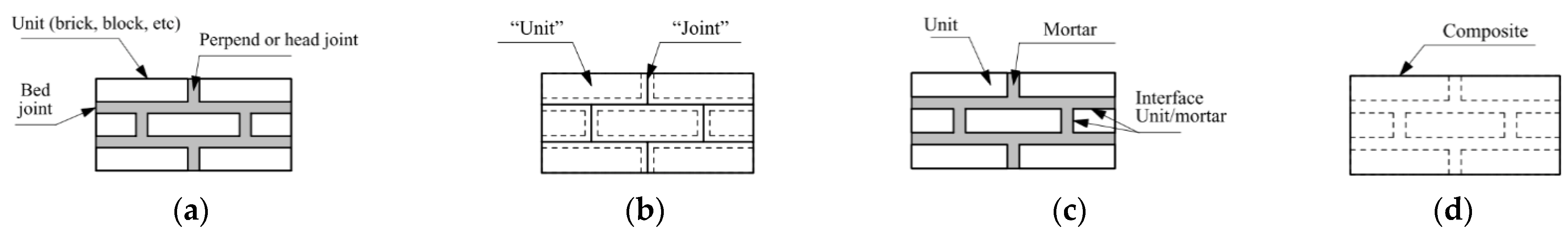
There are two main approaches for numerical studies on infill masonry walls: micro-modelling and macro-modelling. The micro-modelling is a refined/detailed strategy in which all the elements composing the wall are modelled, with masonry units and mortar joints as volumetric elements and boundary link-models simulating the contact and friction conditions between the individual elements and the frame. A simplified approach within micro-modelling involves reduced number of elements by combining a brick with the surrounding mortar, which is connected to the rest by link-models. These approaches are expensive on modelling time and computational demands, especially when applied to dynamic and non-linear analysis. Macro-modelling is a simplified approach in which the infill masonry wall is reduced to a shell element or to a set of struts working in the diagonal compressive zone of the infill. The equivalent struts are by far the most used technique, and therefore there are a great number of variations, such as single strut models connecting opposite nodes, or multi-strut models with different unloading schemes, connecting column-to-column, beam-to-beam or node-to-node (the latter combining both column and beam stress redistributions). This macro-modelling approach is very useful since it can be much lighter on computational resources, facilitating the analysis of complex and entire structures representing actual infilled RC structures. The works of Crisafulli (1997) and Asteris et al. (2011, 2013) contain an extensive, organised, and in-depth state-of-the-art review on infill masonry modelling, both for macro- and micro-modelling approaches [7,232,233].
Based on definitions given by Asteris et al. (2011, 2013), a comparison and the advantages of each modelling strategy is presented in Table 6 [232,233].
6.1. Macro-Modelling
The macro-modelling with equivalent diagonal struts was originally developed to enable numerical analysis of infilled frames with higher shear stiffness. From its evolution, with multi-strut models it was possible to integrate shear and tensile stresses within the contact length between wall and frame. Models have started to become more complex, with some considering the reduction of stiffness and strength under dynamic loads, or other equivalent approaches such as shear slip at the middle of the infill walls. One of the aspects yet to be developed involves the out-of-plane behaviour, which becomes an important issue when combined with the diagonal cracking created by in-plane demands on the masonry infill walls. The following two sections describe the evolution of macro-modelling approach, supported with tables and figures to better illustrate modelling procedures.
6.1.1. In-Plane Models
Polyakov (1956, 1967) was the first author to suggest the use of an equivalent diagonal strut [104,234]. The proposal was based on experimental studies on steel frames with focus on normal and shear stresses on the infill walls, in which it was observed that stresses were transferred from the structure to the non-structural elements only by the compression corners of infill-frame interfaces. The authors developed a numerical technique to estimate the required load intensity to create diagonal cracking.
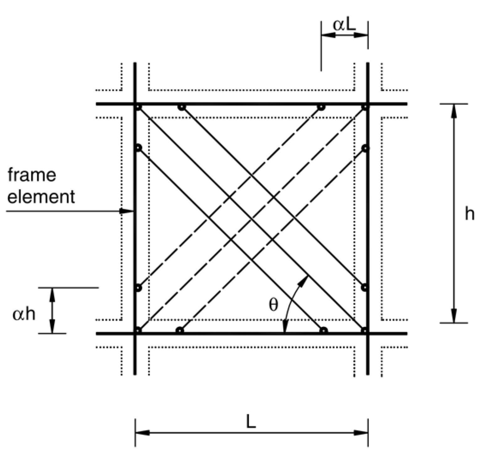
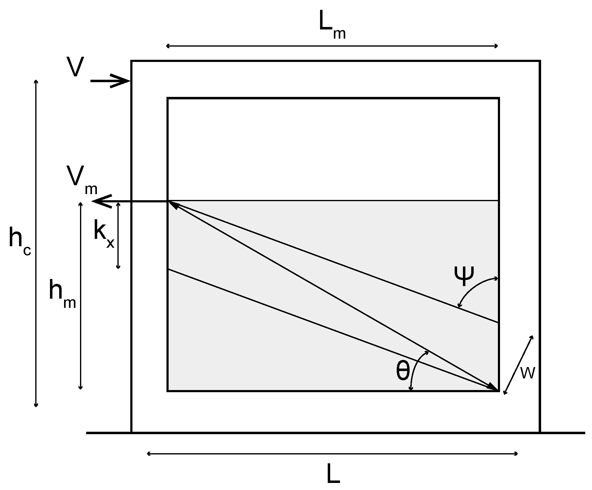
Holmes (1961) improved the previous concept being the first author to propose a formulation for the diagonal strut (see Figure 3) [99]. The proposed formula for the width of the equivalent strut (see Table 7) was calibrated for steel frames with brickwork and concrete infill walls considering deformation and ultimate strength of the system. The proposal triggered several other studies to define the width more accurately.
Stafford-Smith (1962), using experimental data of steel frame infilled with concrete mortar, concluded that the width of the equivalent strut should depend on the contact of the infill in the frame [235]. The conclusion was drawn from the observation of increased stiffness when a wider compression (contact length) was realised. Thus, he proposed a different width for the equivalent strut (see Table 7) depending on the proportions of the infill wall.
Stafford-Smith (1968) and Stafford-Smith and Carter (1969), using experimental data from Stafford-Smith (1966, 1967), suggested a more thorough way for computing the equivalent strut width (see Table 7), taking into account the properties of the infilling and concrete, proportions and thickness of the infill wall [102,106,109,248]. Empirical curves were assessed by considering the interaction between frame and infill as triangular distribution forces. Most models are still based on this assumption due to its level of accuracy, employing the relative stiffness formulation:
where Ec the Young’s modulus of the frame, Em the Young’s modulus of the masonry wall, Ic moment of inertia of the column and t the wall thickness.
An analytical formulation was also proposed to compute the lateral stiffness for hinged nodes by:
and for rigid nodes by:
where the parameters are:
Fiorato et al. (1970) proposed another formulation to compute the lateral stiffness of infilled frames as [110]:
where the shear stiffness is
and the flexural stiffness is
Mainstone and Weeks (1970) and Mainstone (1971) proposed two different calibrations for the equivalent diagonal strut width, using the stiffness parameter proposed by Stafford-Smith and Carter (1969) (see Table 7) [109,115,230]. The authors divided the behaviour of the system, firstly considering perfect frame-infill contact, and secondly assuming that interaction would be restricted to the compressive corners (crushing region). The authors stressed that the relative stiffness of the infill-frame interaction was the most important aspect to be addressed when using an equivalent strut to estimate stiffness and the ultimate strength of the system.
Abdul-Kadir (1974) investigated openings on infill walls and proposed an equation to account the reduced infill stiffness [118].
Klingner and Bertero (1976) modelled the infill masonry walls with two equivalent struts [120]. Apart from the strength and stiffness estimation, it was one of the first works to incorporate hysteretic element response for analysis of cyclic behaviour, also proposing a non-linear formulation of macro-model. An adapted width of the equivalent diagonal strut was also proposed (see Table 7).
Leuchars and Scrivener (1976) proposed a model capable of representing the response when horizontal shear sliding occurs in the masonry panel [119].
Liauw and Lee (1977) suggested a calculation method to compute the stiffness and strength of the equivalent diagonal strut for these conditions [123].
Liauw (1980) and Liauw and Kwan (1984) developed a set of analytical formulations to compute the maximum lateral loading for which shear failure is achieved [125,126]. The formulation was calibrated for steel frames and can be used for infilled frames with or without interface connectors.
Hendry (1981) worked on a semi-empirical calibration for the width of the diagonal strut, based on the Abdul-Kadir (1974) experimental work [118,236]. The proposed value was then used on the Canadian Standard (CSA-S304.1 2004) and corresponds to half of the previously proposed by Stafford-Smith (1962) (see Table 7) [37,235].
Liauw and Kwan (1984), through experimental and analytical study, took into consideration the non-linearities from materials and interfaces, proposing values to represent the contact length between infills with the frame and the dependent width of the equivalent diagonal strut (see Table 7) [238]. The studies can be also found in Liauw and Kwan (1983, 1983) [249,250].
Bazan and Meli (1980) developed diagrams for computing the equivalent strut width, for diagonal cracked infill walls [251]. Later, Tassios (1984) converted those diagrams into formulations, partially available in Table 7 [237].
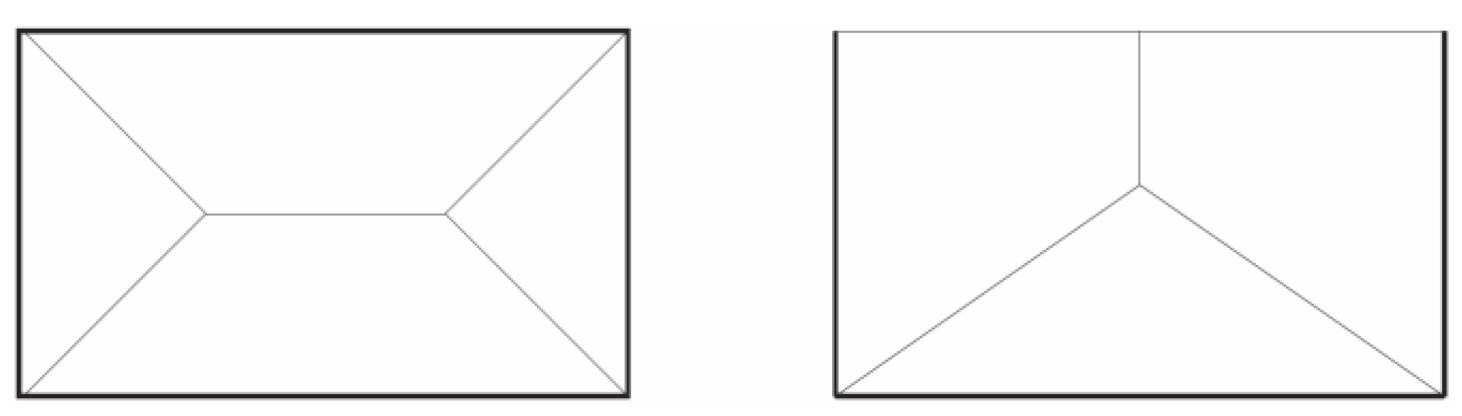
Thiruvengadam (1985) was the first author to propose a multiple-strut model. It was developed to overcome some of the limitations of the single-strut models to compute bending moments and shear forces on the frame elements [252]. The proposed model is not limited to a specific number of struts and can be adapted to different configurations in order to capture cases such as the influence of openings or the separation between frame and infill. Besides shear, axial stiffness was also accounted for as well as vertical stiffness of the infill wall through vertical struts. Despite its increased complexity, the main advantage of the proposed multi-strut model is the ability to represent the actions in the frame more accurately.
Doudoumis and Mitsopoulou (1986) proposed a new model for strength deterioration due to cyclic loading and applied it to an equivalent strut model [253].
Syrmakezis and Vratsanou (1986) used a multi-strut model composed of five parallel struts in each direction, analysing both the strength and stiffness of the infilled system [254]. It was concluded that the definition of the contact length has a major impact on the distribution of moments on the frame, an effect that is not captured by simplified models such as single struts resulting in inaccurate stresses on structural elements.
Decanini and Fantin (1986) suggested a hysteretic model with modified width of the equivalent diagonal strut, depending on the relative wall-frame stiffness (see Table 7) and on the cracking conditions of the wall [239].
Chrysostomou (1991) (also Chrysostomou et al., 2002) investigated the behaviour of infilled frames, focusing on the effects of stiffness’ deterioration and wall strength [255,256]. A modelling strategy was proposed for the wall (for both diagonal directions) with three parallel bar elements, as described in Figure 4. The considered offset length for the strut connectivity coincides with the plastic hinge on column and beam. The model also estimated the stiffness and strength degradation.
Paulay and Priestley (1992) concluded that using a large strut width would result in a stiffer structure and consequently in a higher seismic response [240]. With that concern they proposed a modified strut width (see Table 7).
Hamburger and Chakradeo (1993) proposed a multi-strut model accounting for openings and following a similar proposal by Thiruvengadam (1985) [252,257]. However, the model had its limitation on the difficulty to calibrate the struts.
Mehrabi et al. (1994), employing the Mohr–Coulomb criteria, proposed a formulation for the estimation of the load for which first crack occurs [157], as:
where C is cohesion, Aw horizontal area, μ0 is initial friction coefficient, P is vertical load on the wall, h is the height of the column (measured at the beam axis), and L is the beam’s width (measured at the column axes). Aceq is an equivalent area of infill-columns:
On the other hand, the load for which the wall develops a crushing failure can be computed by:
where α is the width of the diagonal strut, t is the thickness of the strut and is the compressive strength of the masonry. The shear capacity of the wall is computed by:
Moreover, Mehrabi et al. (1994) proposed a series of analytical formulations (not presented here) to compute the resistance, for certain failure mechanisms [157].
Durrani and Luo (1994) also proposed a modified equivalent width (see Table 7), developed from comparison with other models, using semi-empirical formulations [241].
Saneinejad and Hobbs (1995) proposed an analytical non-linear force-displacement model to predict the behaviour up to the ultimate limit load [258]. It consisted of two diagonal and parallel struts in each direction, distributing the loads to the column elements, as seen in Figure 5. The model takes into account ductility limits of the infilled frame, aspect ratio of the frame, shear stresses on infill-frame interfaces and relative strengths between column and beam elements.
Crisafulli and Carr (2007), following studies of Crisafulli (1997), proposed an improved strut model to compute the behaviour of infilled frame systems [7,259]. The model employs six strut members using hysteresis rules. It consists of two diagonal and parallel struts in each direction, which carry the axial loads on the panel, and another pair to describe shear from the top and bottom of the panel. The compressive struts, implemented by Smyrou (2006) on SeismoStruct, distribute the loading through internal and dummy points, located on the joint and on the columns, considering the actual contact of the infill panel when it is deformed (see Figure 6) [260,261]. Crisafulli (1997) compared different one-, double- and triple-strut models, concluding that the double-strut model was the most balanced, achieving accurate results without too much complexity in terms of calibration and computational efforts [7]. According to Crisafulli and Carr (2007) and Smyrou (2006), the model offers limited accuracy on connection to beam-column joints regarding bending moments and shear forces on the structural elements [164,260].
Hendry (1998) defined a width for the equivalent strut (see Table 7) considering uniform compressive stress on the wall [242].
Flanagan and Bennett (2001) suggested a formulation for the area of the equivalent diagonal strut as [243]:
As mentioned before, Chrysostomou et al. (2002) published an improved work started by Chrysostomou (1991), in which a non-linear model with six parallel struts (three in each direction, as seen in Figure 4) was developed that takes into account the strength and stiffness degradation of the infill wall [255,256]. The off diagonals were placed according to the expected formation of plastic hinges on both structural elements, beam and column. The model, developed for dynamic analysis, considered only a set of three struts at a time, when they become compressive on a specific direction of the infill.
Al-Chaar et al. (2002) used the proposed diagonal strut width of Stafford-Smith and Carter (1969) and Mainstone (1971) for solid infill [109,115,167]. Also introduced were some new reduction factors that affect the equivalent strut width to take into account the presence of openings, namely R1:
where Aopen is the opening size and Apanel is the area of the infill panel, and R2 related with damage on the wall, according to Table 8.
Asteris (2003) proposed a series of parameters to modify the width of the diagonal strut taking into account the existence of openings (location and area) on the infill wall (see Figure 7) [262]. The findings were compared with previous analytical work of Giannakas et al. (1987) regarding the influence of the wall openings to the frame behaviour [263].
El-Dakhakhni et al. (2003), following the analytical and experimental work in (El-Dakhakhni 2000; El-Dakhakhni et al., 2001; El-Dakhakhni 2002), proposed a model with three diagonal struts (see Figure 8) in each direction, one in the diagonal of the panel and the other two non-parallel and off-diagonal [8,9,264,265]. According to the researchers their model was more successful in predicting the stiffness of the wall and describing the development of stresses along the frame elements compared to other models with fewer diagonal struts. The model was implemented in ANSYS software (ANSYS-Inc., Canonsburg, PA, USA, 2012) [266]. The frame was modelled with elastic elements with the non-linearities lumped on the frame joints with springs. This simplified non-linear model was capable of computing the frame-infill interaction and corner crushing failure mechanism. The width of the diagonal strut (distance between the struts connected to the frame) used the contact length proposed by Saneinejad and Hobbs (1995) as [258]:
where αc is the ratio of column contact length to height of the column, αb the ratio of beam contact length to span of the beam, h height of the column, l length of the beam, Mpj minimum of the column’s plastic moment capacity, Mpc and Mpb the plastic moment capacity of the column and beam, respectively, and the compressive strength of masonry panel, parallel and normal, respectively, to bed joints and t the thickness of infill wall.
For the area of the diagonal struts, El-Dakhakhni et al. (2003) [9], suggested A1 = A/4 for the off-diagonal struts and A2 = A/2 for the diagonal one, where the total area A was computed by
where t the thickness of the infill, and θ = tan|−1(h/l)| the diagonal angle. A stress-strain model was proposed for the masonry infill panel, as shown in Figure 9, computed by ε1 = εp − 0.001, ε2 = εp + 0.001 and ε = 0.01.
Asteris (2008) developed a 2D finite element approach proposing a new methodology to account for the contact and separation between the frame and the infill walls [267]. The frame was modelled with plane beam elements and the masonry infill with an isoparametric rectangular element with eight degrees of freedom. When the load is applied, it begins with the infill element connected to one of the nodes of frame column-beam connections, and then, an iterative process is initiated in order to rerun the analysis until the infill element is not overlapping with the frame elements. Another check is then performed in order to assess the separation of infill-frame according to which, if tensions are computed on those connections, then the points are not linked.
Kadysiewski and Mosalam (2009) proposed an analytical model capable of simulating both in-plane and out-of-plane behaviour of the infill walls, with a single diagonal beam-column element having a node at midspan, with a concentrated mass, that introduces out-of-plane inertial forces [268]. The beam-columns were developed as force-based elements, with concentrated plasticity at their extremities. The interaction modelling was based on experimental work (Hashemi and Mosalam 2006) and on numerical work (Hashemi and Mosalam 2007) [194,269].
Amato et al. (2009) employed a model with an equivalent diagonal strut, proposing verification of the local effects through eccentric evaluation [244]. Furthermore, a modified width for the equivalent diagonal strut was proposed as shown in Table 7.
Rodrigues et al. (2010) utilised a simplified macro-model, previously suggested by Varum (2003), based on an equivalent bi-diagonal compression strut model, in which four rigid struts are connected to a central element containing all the non-linear behaviour of the masonry wall [231,270]. This simplified approach offers the capability to simulate both flexural and shear behaviour, and incorporated strength degradation of the infill (Figure 10a,b).
Parchuri and Kaushik (2011) proposed modified length of contact and widths for the off-diagonal struts (Table 7) [246]. In the study, the infill was modelled by three parallel struts as proposed by Chrysostomou (1991) [255].
Pradhan et al. (2012) studied partially infilled frames, suggesting some adaptations for the width of the equivalent diagonal width, as shown in Table 7 [247]. Figure 11 presents one example of a strut applied on a partially infilled frame, with the respective width.
More recently Yekrangnia and Asteris (2020) proposed a multi-strut model for the prediction of the force and displacement behaviour of masonry infills with openings, taking into account their position in the infill [271]. The calibration of the model was supported by finite element analyses and a suggested a new reduction factor that compensates for the presence of openings.
6.1.2. Out-Plane Models
Regarding out-of-plane analytical work, some models were developed to assess the out-of-plane behaviour of infills. One of the first and simplest, is proposed by Timoshenko and Woinowsky (1959), considering an elastic plate solved by a classical approach [272]. Other works considered two-way inelastic behaviour based on the yield-line theory, amongst others by Drydale and Essawy (1988), Haseltine (1976), Haseltine et al. (1977), and Hendry (1973). Flanagan and Bennett (1999) compared the proposals of Angel et al. (1994), Klingner et al. (1996) and Dawe and Seah (1989), assessing that the yield-line theory approach achieved results closer to experimental data [146,156,171,273,274,275,276,277]. Dawe and Seah (1989) was also used by Hashemi and Mosalam (2007) in the development of the out-of-plane macro-model [146,269]. Two formulations were proposed to compute the ultimate out-of-plane load (see Figure 12 with yield-lines), assuming collapse by arching mechanism. The formulations were proposed for three supported edges and for four/full supported edges, respectively, as:
with coefficients
where qult is in kPa, α should have an upper limit of 75 and 50, respectively, for three-support and fully supported, and β should have an upper limit of 50 in either case.
A great number of numerical and analytical analyses with macro-models have been performed. Some of those works can be found in (Klingner and Bertero 1978; Sobaih and Abdin 1988; Fardis and Calvi 1994; Negro and Colombo 1997; Fardis and Panagiotakos 1997; Kodur et al., 1995; Balendra and Huang 2003; Crowley and Pinho 2006; Perera 2005; Reflak and Fajfar 1991; Smyrou 2006; Asteris et al., 2011; Chrysostomou and Asteris 2012; Rodrigues et al., 2008; Dias-Oliveira 2013, Muratović and Ademović 2015) [3,10,121,260,278,279,280,281,282,283,284,285,286,287,288,289].
6.2. Micro-Modelling
The modelling of the infilled frames, using diagonal compressive struts is representative mostly under high loading demands, after the infill becomes partially separated by the bounding frame. This can occur due to a number or different reasons, such as the relative wall-frame strength and stiffness properties or properties of interface materials [234]. For this reason, the macro-modelling approach is unable to capture some of the subtleties regarding the complex interaction of an infilled frame system which are more suitably captured micro-modelling. The following paragraphs present modelling strategies developed and used in the literature.
Mallick and Severn (1967) suggested the first micro-model for the analysis of infilled frames, focusing on the contact/interface between wall and frame [290]. The infill walls were modelled by rectangular elastic elements with two degrees of freedom per node, and the frame elements were modelled without consideration of axial deformation. For the interaction of wall-frame slippage was considered, defined through frictional shear forces. The predicted stiffness of the system was in good comparison with experimental work, for aspect-ratio less than 2.
Goodman et al. (1968) developed a joint element (plain strain with four nodes and two transitional degrees of freedom in each node) used to simulate rock masses, which was later adapted and modified for the simulation of interaction between frame and wall [291]. The modified rectangular element is connected with three or two degrees of freedom at the nodes of the frame and infill elements, respectively. The shear strength properties depend on adhesion and friction. King and Pandey (1978), demonstrated with that model the elasto-plastic contact behaviour, with tangential stress-relative displacement curves [292]. Tangential stiffness was then developed according to those analytical findings.
Mallick and Garg (1971) extended the work in Mallick and Severn 1967 by considering gaps between infill and frame [114,290]. In this work, the infill element is modelled in a similar way and the frame elements considers shear and axial deformations, excluding rotational ones.
Kost et al. (1974) observed that the bond between wall and frame was affected by poor construction techniques [293]. Considering reduced tensile strength at the contact regions, it an analytical model was developed to monitor the opening and closing of gaps.
Axley and Bertero (1979) used two finite element schemes to assess the behaviour of infilled frame systems [294]. The first one was used for validation purposes, involved a refined model where the stiffness matrices of the infill and frame were coupled. For the second, the infill stiffness matrix was condensed to the boundary degrees of freedom, resulting in a stiffness matrix of the frame-infill system having reduced degrees of freedom.
Liauw and Kwan (1984) modeled numerically experimental works for monotonic loading, resulting in good approximations [238]. A bar element was used for the infill-frame interaction with both slip and separation capabilities, and a triangular plain stress element for the infill itself, with different properties in compression (nonlinear material) and in tension (brittle material). The model allowed the characterisation of different failure modes, such as corner crushing on infills with fracture on columns or beams, and diagonal cracking on infills.
Rivero and Walker (1984) performed dynamic analyses aiming to develop a non-linear model to study the behaviour of infilled frames, in terms of interaction on the infill-frame interface and cracking/failure of the wall [295]. Two types of elements were used for the interaction, one as gap element (for no-tangential stress conditions) and another as connection element (for contact conditions).
Dhanasekar and Page (1986) studied numerically brick masonry infill walls, developing a finite element model that included elastic properties, inelastic stress-strain relations, and a failure surface [296]. It was formulated with non-linear isotropic elements with six nodes, while brick units and mortar joints were modelled separately.
Dawe and Seah (1989) developed a computer program in order to analyze analytically pushover experimental data [145]. The frame was modelled with non-linear behavior lumped at the end of each member. The infill masonry was modelled by a set of elastic and rectangular elements connected with each other by joints having tensile and shear capacities. In order to capture tensile failure on the elastic elements (simulating bricks), virtual joints were introduced.
El-Haddad (1991), using the finite element method and fracture mechanics techniques, developed a computer model to analyse cracked frames with masonry infill [297]. The cracked frame members were then updated on their stiffness matrix to account for the new conditions of axial, flexural and shear deformations. The infill masonry walls were modelled by a plane stress element with four nodes. The structural analysis took into account both infill contact length and infill-frame relative stiffness. The model could be used to assess overstressed regions in buildings due to structural cracking and separation between frame and infill.
Some researchers, such as Rots (1991), Lotfi and Shing (1994), Lourenço (1996), Mehrabi et al. (1994) or Mehrabi and Shing (1997) tested the validity of continuous-interface models regarding the behaviour of mortar joints, accounting for the interaction between normal and tangential stresses [157,298,299,300,301]. In those studies, authors used a set of different modelling strategies, modelling components—concrete, ties, bars, masonry and mortar –separately.
Lourenço (1996) proposed a model that combined coulomb friction, tension cut-off and compression cap [300]. A simplified micro-modelling technique was suggested lumping interface-mortar-interface in one discontinuous element. Thus, damages were concentrated: (1) in the mortar joint, and (2) in the pure tension surface in the middle of the masonry unit. The approach has computational advantages, and the capability to simulate the behaviour of the masonry considering the cracking on bed joints, head joints and of the masonry units. Approximate formulas are given to compute the stiffness of the interface elements. The normal stiffness, as:
and shear stiffness, as:
where Eu and Em are the modulus of elasticity of masonry unit and mortar joint, respectively, Gu and Gm are the shear modulus of masonry unit and mortar joint, respectively, and hm the thickness of the mortar joint.
The simplification proposed by Lourenço (1996) is described in Figure 13c [300]. Typical strategies for the micro-modelling of actual masonry walls (Figure 13a) involve three-phase material (Figure 13b), where units, mortar and their interface are modelled as continuous and discontinuous elements, respectively. Lourenço (1996) proposed a simplified micro-modelling with two-phase material (Figure 13c), where the units are still represented by continuous elements, but the mortar and interfaces are lumped to discontinuous elements [300]. An even more simplified strategy that blurs the space between macro-models and micro-models, namely called semi macro-modelling involves one-phase materials (Figure 13d), where units, mortar and interfaces are combined into a homogeneous and continuous element.
Mehrabi and Shing (1997) investigated the behavior of RC concrete frames infilled with concrete masonry units using a simplified approach [301]. A smeared-crack element was utilised to model both the frame and the masonry units along with constitutive models to account for the mortar joints, assuming elastic behaviour under compression stresses of the interfaces. The proposed modelling was capable of assessing cracking, crushing, and sliding under cyclic and monotonic analysis. Mehrabi and Shing (1997) concluded that the use of bond-slip elements between frame and infill resulted more accurate results, compared with experiments instead of ignoring them [301]. Although the results were close to experimental data in terms of peak capacity, the behaviour of the analysed system was not similarly close.
Singh et al. (1998) developed a model to compute the non-linear behaviour of infilled frames. The frame was modelled with bar elements employing a special formulation [302]. The infill was modelled as a continuous material assuming elastic response up to the failure. For the characterization of cracking and crushing failure the Von Mises criterion was adopted with tension cut-off. Shear failure on both frame and infill elements was concluded to be not satisfactory with the used modelling strategy.
Chiou et al. (1998, 1999) implemented the discontinuous deformation analysis to model infill masonry walls through sub-blocks connected by joints having tensile and shear strength [169,303]. The complete system was assembled using different strategies for concrete and steel elements. The results were found to be in agreement with experimental work. The model did not consider mixed tension-shear failure on joints, nor tensile failure on the sub-blocks, using linear constitutive relations.
Dawe et al. (2001) (following Dawe and Young 1985) proposed a simplified computer model, using linear finite elements [138,304]. Spring elements were used in order to simulate the interface conditions between infill and frame, in terms of bond, friction, separation and re-contact, with the capability to assess the failure on the interfaces too. The model also accounted for non-linear behaviour duet to tension cracking, crushing and shear failure of the infill. The model was calibrated with experimental results published in Schmidt (1989) [148].
Asteris (2003, 2005, 2008) focused on contact conditions of infill-frame systems. In this context, a finite element technique was proposed, employing an iterative process to find the geometrical equilibrium conditions of the system [262,267,305]. The equilibrium assures that the infill does not overlap with the frame, with only two interface conditions considered: contact or separation. The technique can predict the influence contact conditions can have on the infill stiffness. The same technique was used to study openings on infill walls, leading to the following stiffness reduction factor:
Shing and Mehrabi (2002) studied the non-linear behaviour of masonry wall elements using the plasticity theory [11]. Cracking in brick-mortar and mortar-frame were considered. The system was expected to be homogeneous and isotropic up to the occurrence of cracking, followed by elasto-plastic material behaviour, based on the Rankine/Von Mises crack criterion.
Zhuge and Hunt (2003) studied the response of masonry walls using a discrete element approach [306]. The assembly of the infill panel was simulated through discrete blocks connected by joints modelled as surface contacts capable of computing the separation and sliding between the units/blocks.
Basiouny and Ghobarah (2008) proposed a simplified model, in between micro- and macro-modeling approach [307]. The model uses the Drucker–Prager failure criterion for 10 plane elements simulating the behaviour of the masonry. Each node has two degrees of freedom, whereas these planar elements are connected with each other and to the bounding frame through contact-interface elements (zero-length). The model is able to capture various failure modes, such as flexural, shear, diagonal and crushing modes.
Al-Chaar et al. (2008) used commercial software to micro-model RC infilled frames [308]. The smeared-crack constitutive model was used for the continuous elements (brick units and concrete) adopting the proposal of Lourenço (1996) for the interfaces (mortar joints) [300]. The interface model was based on the Coulomb friction model combined with tension cut-off and elliptical compression (Figure 14), which was not considered adequate to capture the cumulative damage occurring on the mortar joints. The model failed its validation through experimental results, needing further calibration of its parameters.
Stavridis (2009) and Stavridis and Shing (2010) combined the smeared and discrete crack approach on a new modelling methodology that was able to evaluate different infill failure modes, mortar joint shear failure, and shear failure on columns [206,309]. From a parametric study, it was assessed that mortar joint properties were the most influential compared to concrete or brick properties. Koutromanos (2011) and Koutromanos et al. (2011) extended the approach, with the use of a cohesive crack interface model and improved smeared-crack model, suitable for cyclic behaviour [310,311]. The methodology was considered accurate in terms of load-displacement response, crack patterns and prediction of failure mechanisms.
D’Ayala et al. (2009) and Ellul and D’Ayala (2012) numerically studied infilled frame systems using different software with refined models, focusing on the interface parameters [312,313]. In their studies, the authors highlighted the importance of accurately estimated column shear failure in order to correctly assess an infilled frame for seismic demands.
Stavridis and Shing (2010) and Stavridis (2009) used the finite element method employing commercial software FEAP (Taylor 2007) to combine smeared and discrete cracking, capable of describing different failure modes of the system [207,309,314]. Under the proposed modelling strategy each infill is modelled with smeared-crack elements connected with interface brick elements and interface for mortar joints, enabling the model of shear cracking at the unit and joint levels. The materials were modelled through elastic-plastic law adopting von Mises failure surface with tension cut-off (see Figure 15), given by:
and
where J2 is the second invariant of deviatory stress, σe is the effective plastic stress tensor, and εp is the plastic strain tensor.
Cavaleri et al. (2020), studied through finite element modelling the out of plane behaviour of infilled panels, prior damaged due to in-plane cyclic actions and suggested formulas for the strength and stiffness deterioration inflicted by the latter [315].
6.3. Reinforced Concrete Models
6.3.1. Concrete Material
The use of accurate models for both concrete and steel components is decisive in order to simulate accurately this type of complex analysis. The difficulties which are inherent to the dynamic/cyclic behaviour are challenging, but the use of iterative processes becomes accessible using computer software, which was not available to past researchers.
Penelis and Kappos (1997) highlight the importance of describing the envelope curve of concrete cyclic behaviour as much accurately as possible, preventing errors from analysis under monotonic loading [316]. The experimental results usually have a big correlation between monotonic and cyclic loads, supporting their conclusion. Hereupon, the concrete cyclic behaviour also will also be examined.
One of the first known researchers to work on the modelling of concrete cyclic response, Karsan and Jirsa (1969), specified through experimental work the point where two branches of unloading and loading meet, linking successive such points through second degree parabolas [317]. One limitation of the model is it does not take into account the confinement conditions provided by the stirrups.
Later, Blakeley and Park (1973) developed a simplified model capable of computing the envelope curve of the concrete [318]. For the unloading behaviour, the model utilises a straight line with simplified assumptions regarding non-energy dissipation or stiffness deterioration for strains equal or smaller compared to the peak stress. The reduction of stiffness is calculated through a processed parameter. The loading is accomplished through two straight lines, the first one 50% stiffer than the calculated for unloading until the maximum past strain and followed by a vertical line up to the lastly recorded stress.
Yankelevsky and Reinhardt (1987) proposed a model focused on the unloading and reloading behaviour, considering that the envelope curve is already given [319]. The model considers a linear shape for the cyclic branches with varying stiffness depending on previous strain ranges.
Mander et al. (1988) proposed a simplified version of the Karsan and Jirsa (1969) model that included the tensile stress-strain relationships and employed equations proposed by Popovic (1973) for the envelope curve, accounting for the confinement conditions [317,320,321]. The model calibrates inelastic strain each time that a new maximum strain is recorded, allowing it to estimate the cyclic behaviour for even greater strains. Martínez-Rueda and Elnashai (1997) modified the model, enhancing numerical stability which was lacking for large displacements of the modification involved three different phases for the calculation of inelastic strains, instead of a single parameter in Mander et al. (1988), accounting for softening of concrete, and the curve shape meeting the envelope on reloading [320,322].
An efficient definition of the concrete model is very important in order to compute the formation of plastic hinges during the seismic excitation and also simulate the ductility of the material that allows for moment redistribution between element members. The distinction between confined concrete on the core, provided enough stirrups are applied, and non-confined cover concrete is important since the former can deal with much higher stresses and, in the case of old RC buildings, it is necessary to assess the confinement factor because potentially the stirrups were applied, with no clamping provisions, which are predicted on the new codes. If the stirrups are not sufficiently clamped, they could open wide negating any confinement conditions to the concrete core.
6.3.2. Steel Material
The steel impact on the cyclic response of RC structures can be drastic, depending on the amount of reinforcement. Its behaviour, compared to concrete, is more predictable but certain characteristics change under cyclic excitations. Both materials are important in maintaining the safety of a structure, but an incorrect amount of steel can lead to weak capacity of the affected members under high bending moment demands expected during an earthquake.
Yu (2006) points out, from past research, that macroscopic material models offer the best numerical approach to simulate steel response [323]. It is also referred that the use of recent models can already be accurate enough for engineering regarding strain and stress results.
In terms of non-linear analyses, some models were developed and can be grouped in different approaches, as Linear Elastic-Perfectly Plastic, Linear Elastic with strain hardening, Linear elastic with non-linear hardening and Ramberg-Osgood model [324].
In terms of cyclic behaviour, several investigators developed and discussed several models throughout history. Some of these models are summarised in this section and afterwards discussed in comparison to the model used in this work. Two of the first researchers, Dafalias and Popov (1976), examined different models of purely kinematic and purely isotropic hardening [325]. From the two approaches, some disadvantages were pointed out, such as, inaccuracy regarding the stresses after yielding, using isotropic models while kinematic models could not take into account the quick reduction of elastic stresses after plasticity due to lack of isotropic hardening. Therefore, Popov and Petersson (1978) developed another model, solving some limitations, using a “multi-surface” model capable of creating a real transition between monotonic and cyclic behaviour of the material [326]. Santhanam (1979) presented a simplified linear model accounting for the effects of cyclic stiffness degradation and the fact that yield stress growth was not accurate enough to predict its behaviour in loading and unloading without considerable plastic flow [327]. Tseng and Lee (1983) used a two-surface model based on an isotropic hardening approach that implements a bounding surface for monotonic response, coupled with a reduction of yield surface [328]. Despite its performance in predicting cyclic softening and hardening and stress relaxation well enough, the model could not also compute an accurate loading and unloading behaviour, without considerable plastic flow. Cofie and Krawinkler (1985) used some past relationships to support a similar model. However, its performance in this matter was still not flawless because it did not update enough parameters related with the cyclic strain amplitude [329].
The next two models were a modification of Ramberg–Osgood model, a non-linear equation able to compute the stress-strain relationship and especially the transition at yielding and the strain hardening of materials such as steel. In Ma et al. (1976) the model was modified to achieve a cyclic response, but according to Elnashai and Izzuddin (1993), it developed an overestimated cyclic response and good results for monotonic response [330,331]. Menegotto and Pinto (1973) presented a stress-strain relationship which would be later modified by Filippou et al. (1983) that included some isotropic hardening rules [332,333].
7. Final Remarks
7.1. Earthquake Lessons
The observed damages after earthquake events show a great impact of the infill masonry walls on the behaviour of RC buildings. The study showed that the influence of these non-structural elements is not only affecting their particular stability, but it can have a massive influence on the structural vulnerability and direct human hazards either by in-plane or out-of-plane or combined loading. The complexity and vulnerability increase by the interaction between the structural and non-structural elements. The most common deficiencies and damages are:
- Stirrups and hoops (inadequate quantity and detailing),
- Detailing (bond, anchorage and lap-splices),
- Inadequate capacity and failure (shear, flexural),
- Inadequate shear capacity of the joints,
- Strong-beam weak-column mechanism,
- Short-column mechanism,
- Structural irregularities (in plan or in elevation: torsion, soft-storey, etc.),
- Pounding,
- Damages in structural secondary elements (cantilevers, stairs, etc.), and
- Damages in non-structural elements.
It is possible to separate them into vulnerabilities on primary structural elements for items [1,2,3,4,5,6,7,8], on secondary structural elements for item [9], and for non-structural elements for item [10]. Changing the perspective, it can be claimed that non-structural vulnerabilities are not only 1 in 10 but actually 7 in 10, if the interaction behaviour is considered on items [3,4,6,7,8,9,10]. The items were described in Section 4.
The value of this conclusion becomes even greater since infill masonry walls feature a brittle behaviour, and they are not designed for seismic actions, often not having sufficient capacity for non-accident conditions, and the seismic codes do not fully account their influence yet, on the design and assessment of new and existing structures.
From recent experiences in Europe, on earthquakes Italy, Spain, Greece, Albania or in Croatia, most damages on buildings originated from non-structural elements, while buildings collapses occurred from irregularities, especially in elevation. The verified structural damages were mostly in columns and joints (and also RC walls) due to insufficient shear capacity, due to bad detailing/designing or infill masonry interaction. From other analysed events the influence of the infill walls was also highlighted. The most common damages are caused from irregularities in elevation and plan (the cause for most collapses is the formation of soft-storey mechanism), conditions that lead to formation of short-column mechanisms, insufficient reinforcement or bad detailing for shear stress on columns, and also damages originating from poor concrete quality.
7.2. Structural Codes
Existing codes are not fully prepared to acknowledge infill masonry walls in the design of new or seismic assessment of existing infilled frame buildings, however, most specify recommendations about them. Some of them are the following:
- Dynamic analysis on irregular buildings,
- Empirical formulas to compute the natural period of the structure,
- Minimum seismic design ratio for the structural elements, preventing the resistance of the structure to be decided by brittle infill walls,
- Recommendations regarding irregularities in plan and in elevation,
- Lower response by reducing factors for structures with infill walls compared to bare-frame structures, in order to compensate for increased uncertainties and the decrease of ductility of the building,
- Limitation of deformations to control damage,
- Specifications for wall slenderness to prevent out-of-plane collapses,
- Suggestions regarding openings, and
- Suggestions regarding retrofitting of the walls.
The Eurocode 8 was discussed in terms of ductility requirements and the position of the standard towards infill masonry walls. Eurocode does not encourage the use of beneficial effects of infills by imposing lower response reduction factors for structures with infill walls. It makes recommendations regarding distribution/location of the infills, and for the case of structural connections between the infill and frame, the structure should be designed as a confined masonry building. The non-linear response demands by the modern codes, in order to achieve higher ductility levels, are increasing the demands over the infill walls.
7.3. Experimental Work
A short list of factors and its consequences determining infill masonry behaviour are described next. The list is general since some researchers reached to slightly different conclusions.
- Wall aspect-ratio (height/length)—Decrease of aspect-ratio leads to an increase of the ultimate capacity.
- Boundary conditions of frame-infill—Initial stiffness is not affected; The presence of gaps decreases substantially the ultimate capacity of the frame.
- Gaps on infill-frame interface—Masonry still contributes to the horizontal strength of the system, but the efficiency is affected.
- Wall stiffness—Stiffer walls allow higher load carrying capacity; Building stiffness does not increase linearly with the number of walls.
- Openings on the walls—They decrease the ultimate capacity; Openings near edges reduce more the load capacity of the wall compared to centered openings; (usually) they increase the ductility of the system.
- Reinforcement of masonry wall (i.e., mesh reinforcement)—Increases both initial stiffness and ultimate capacity.
- Gravity loading on columns—Higher level of vertical loading leads to an increase of stiffness and resistance of the system due to increased confinement of the wall.
- Frame stiffness—Stiffer frames lead to higher ultimate capacity of the system, offering better confinement and contact between frame and infill.
- Bonding quality between wall and frame—Affects the ultimate capacity of the system.
- Position of infill—Eccentricity of the wall relative to the panel middle leads to out-of-plane bending effects, reducing both initial stiffness and ultimate capacity of the system.
- Horizontal bond beam and other retrofitting strategies –capable of increasing the ductility of the system.
Table 5 has presented some aspects regarding experimental works, while a visualised summary is depicted in Figure 16. The data are organised into chunks of five years for better visualisation of the trend. The global tendency until last year is linear and growing. The monotonic tests have been substituted by cyclic tests over the years, which are more appropriate to assess the seismic behaviour of the system. Dynamic, in shake-tables, or pseudo-dynamic strategies are increasing slowly due to the costs associated with them.
7.4. Numerical Modelling
In the last 30 years, several numerical modelling studies for the infill masonry walls have been developed with different levels of refinement or complexity. Regarding non-linear analysis of buildings, the macro-models have shown to be the most suitable due to their minor computational impact compared to micro-models. Micro-modelling, on the other hand, is more suitable for research on topics that demand a higher level of local detailing. Macro-modelling has to be validated with empirical results and micro-modelling studies.
In the literature, most macro-models simulate the diagonal compressive behaviour of the infill walls through a diagonal equivalent strut. This simplified approach, though accurate at global level, has some limitations at local level, such as lacking shear redistribution on the structural elements, or the out-of-plane interaction/failure while subjected to in-plane damage. The macro-modelling review identified the deficiencies, and which areas still need more study. Two aspects that are innovative and need more contributions are (1) interaction between in-plane and out-of-plane damage, assessing a formulation that can describe the failure curve, (2) double-leaf wall modelling strategies, since they are particularly vulnerable to out-of-plane collapse, and (3) simplified models that can incorporate retrofitting on walls to mitigate the vulnerability of RC buildings.
A non-exhaustive review regarding the available macro-models has been discussed before and is summarised in Table 9. A collection of different models and strategies have been proposed, suggesting improvements on the compressive strength, stiffness, hysteretic response and shear strength capacity.
The reviewed proposals for the effective width of equivalent struts for infill masonry walls have variations between 10% and 35%. This confirms the complexity and uncertainty inherent in this subject that is greatly affected by a large number of qualitative and quantitative variables. From the review of numerical models, it was pointed out that a difference of 20% between experimental and numerical results should be considered a good approximation for a model. Since the uncertainty on these elements cannot be suppressed, that 20% margin can be used as a confirmation boundary to assess correlation between chosen empirical data and numerical results.
7.5. Conclusions
Infill masonry walls are an important and yet not fully developed topic on structural design considering seismic events. The related motivations and interest relate to the mitigation of risk, specifically in structural vulnerability, and also the economic impact (damage repair, human care, etc.). H. Tiedemann and Hellenic Association of Schools (Lourenço et al., 2009) for past earthquakes concluded that the total costs associated with repairs due to non-structural elements range from 60% to 80% (considering infill walls and other installations) [338].
Previous studies have already shown that infill panels can increase the stiffness, the strength, overall ductility, and energy dissipation capacity of the structures in case of an earthquake. Therefore, infill panels have indeed structural qualities for earthquake conditions, taking a key role on the structural response.
The seismic design strategies place high ductility requirements for RC buildings. The damages observed after earthquake events show that, even for countries with robust seismic codes, vulnerabilities related with infill masonry walls remain an issue. Damages are concentrated on infill walls, and that influences the structural behaviour leading to collapse in several buildings due to formation of soft-storey and short-column mechanisms.
Regarding damages on infill walls, the critical in-plane failure modes are the corner-crushing (excessive compressive demand) and sliding-shear (failure on mortar bond layers). The out-of-plane failure, a very brittle and dangerous type, depends on support conditions of the frame, slenderness of the wall, and in-plane damage combination (studies point to a 50% out-of-plane strength reduction). This type of failure is particularly important for double-leaf walls. The knowledge in this field is still very limited, therefore the characterization of the infill walls’ behaviour when subjected to simultaneous in-plane and out-of-plane loading is still lacking and more experimental and numerical studies are required.
This topic has progressively become part of researchers’ efforts, to develop models and implementation on software programs, both micro-models (local level, more hardware efforts and more complex) and macro-models (analysis of the entire panel as a simplified element). The interaction of in-plane and out-of-plane behaviour of the infill walls and the out-of-plane vulnerability of double-leaf walls were identified as lacking infill masonry modelling approaches to implement in global building analysis.
The author concludes this document citing Asteris et al. (2011a): The issue of modelling infill walls is still an open one, despite the long and rigorous attention that it has received from the research community over the years [233].
Funding
This work was financially supported by: Base Funding—UIDB/04708/2020 and Programmatic Funding—UIDP/04708/2020 of the CONSTRUCT—Instituto de I&D em Estruturas e Construções—funded by national funds through the FCT/MCTES (PIDDAC). This work was also supported by the Foundation for Science and Technology (FCT)—Aveiro Research Centre for Risks and Sustainability in Construction (RISCO), Universidade de Aveiro, Portugal [FCT/UIDB/ECI/04450/2020].
Institutional Review Board Statement
Not applicable.
Informed Consent Statement
Not applicable.
Data Availability Statement
Data sharing not applicable.
Conflicts of Interest
The authors declare no conflict of interest.
References
- Silva, V. Development of Open Models and Tools for Seismic Risk Assessment: Application to Portugal. Ph.D. Thesis, University of Aveiro, Aveiro, Portugal, 2013. [Google Scholar]
- MunichRe. Topics Geo: Natural Catastrophes 2011 Analyses, Assessments, Positions; 2012 Issue, MunichRe: Munich, Germany, 2012. [Google Scholar]
- Dias-Oliveira, J. Seismic Assessment of Existing Concrete Buildings. Master’s Thesis, University of Aveiro, Aveiro, Portugal, 2013. [Google Scholar]
- Fardis, M. Seismic Design, Assessment and Retrofitting of Concrete Buildings: Based on EN-Eurocode 8; Geotechnical, Geological and Earthquake Engineering; Springer: Berlin/Heidelberg, Germany, 2009. [Google Scholar]
- Kritikos, A.I.; Ntasis, G.D.; Zitouniatis, D.G.; Lemonis, M.E.; Asteris, P.G. Lateral response evaluation of steel frame structures with masonry infills. In Proceedings of the 6th ECCOMAS Thematic Conference on Computational Methods in Structural Dynamics and Earthquake Engineering (COMPDYN 2017), Rhodes Island, Greece, 15–17 June 2017. [Google Scholar]
- Lemonis, M.E.; Asteris, P.G.; Zitouniatis, D.G.; Ntasis, G.D. Modeling of the lateral stiffness of masonry infilled steel moment-resisting frames. Struct. Eng. Mech. 2019, 70, 421–429. [Google Scholar]
- Crisafulli, F.J. Seismic Behaviour of Reinforced Concrete Structures with Masonry Infills. Ph.D. Thesis, University of Canterbury, Christchurch, New Zealand, 1997. [Google Scholar]
- El-Dakhakhni, W.W. Experimental and Analytical Seismic Evaluation of Concrete Masonry-Infilled Steel Frames Retrofitted Using GFRP Laminates. Ph.D. Thesis, Drexel University, Philadelphia, PA, USA, 2002. [Google Scholar]
- El-Dakhakhni, W.W.; Elgaaly, M.; Hamid, A.A. Three-strut model for concrete masonry-infilled steel frames. ASCE J. Struct. Eng. 2003, 129, 177–185. [Google Scholar] [CrossRef]
- Asteris, P.G.; Kakaletsis, D.J.; Chrysostomou, C.Z.; Smyrou, E. Failure modes of infilled frames. Electron. J. Struct. Eng. 2011, 11, 11–20. [Google Scholar]
- Shing, P.B.; Mehrabi, A.B. Behaviour and analysis of masonry-infilled frames. Prog. Struct. Eng. Mater. 2002, 4, 320–331. [Google Scholar] [CrossRef]
- CEN. Eurocode 8: Design of Structures for Earthquake Resistance—Part 1: General Rules, Seismic Actions and Rules for Buildings; European Committee for Standardization: Brussels, Belgium, 2003. [Google Scholar]
- SNIP-II-7-81; Building Code on Construction in Seismic Areas. The Ministry for Construction of Russia: Moscow, Russia, 1996.
- NZS1170.5; Code of Practice for the Design of Concrete Structures, Part 1. Standards Association of New Zealand: Wellington, New Zealand, 1995.
- NZS:1170.5:2004; Structural Design Actions Part 5: Earthquake Actions. Standards New Zealand: Wellington, New Zealand, 2004.
- ICC. IBC—International Building Code; International Code Council: Reston, VA, USA, 2003. [Google Scholar]
- Chronopoulos, M.; Chronopoulos, P. Recent Greek provisions for RC structures with urm infills. Open Constr. Build. Technol. J. 2012, 6, 92–112. [Google Scholar] [CrossRef]
- Nazief, M. Finite Element Characterization of the Behaviour of Masonry Infill Shear Walls with and without Openings. Ph.D. Thesis, University of Alberta, Edmonton, AB, Canada, 2014. [Google Scholar]
- Kaushik, H.B.; Rai, D.C.; Jain, S.K. Code approaches to seismic design of masonry-infilled reinforced concrete frames: A state-of-the-art review. Earthq. Spectra 2006, 22, 961–983. [Google Scholar] [CrossRef]
- FEMA. NEHRP Commentary on the Guidelines for the Seismic Rehabilitation of Buildings; FEMA-274; Applied Technology Council: Washington, DC, USA, 1997.
- FEMA. Prestandard and Commentary for the Seismic Rehabilitation of Buildings; Federal Emergency Management Agency: Washington, DC, USA, 2000.
- EAK. Greek Seismic Code; Earthquake Planning and Protection Organization: Athens, Greece, 2000.
- New Greek Code (nGCI). Interventions (and Redesign) of Existing RC Structures; Earthquake Planning and Protection Organization: Athens, Greece, 2012.
- MSJC. Building Code Requirements and Specification for Masonry Structures; Structural Engineering Institute of the American Society of Civil Engineers: Reston, CA, USA, 2011. [Google Scholar]
- IS1893-Part 1; Part I: Criteria for Earthquake Resistant Design of Structures -General Provisions and Buildings. Bureau of Indian Standards: New Delhi, India, 2002.
- SI-413; Design Provisions for Earthquake Resistance of Structures. The Standards Institution of Israel: Tel-Aviv, Israel, 1995.
- NTC08; Approvazione delle Nuove Norme Tecniche per le Costruzioni. Gazzetta Ufficiale N. 29. Ministero delle Infrastrutture: Rome, Italy, 2008.
- Mexican-Code. Complementary Technical Norms for Design and Construction of Masonry Structures; Mexico City Building Code Ltd.: Mexico City, Mexico, 2004. [Google Scholar]
- NBC-105; Nepal National Building Code for Seismic Design of Buildings in Nepal. Ministry of Housing and Physical Planning, Department of Buildings: Kathmandu, Nepal, 1994.
- NBC-201; Nepal National Building Code for Mandatory Rules of Thumb for Reinforced Concrete Buildings with Masonry Infill. Ministry of Housing and Physical Planning, Department of Buildings: Kathmandu, Nepal, 1994.
- NSCP. National Structural code of Philippines, 4th ed.; The Board of Civil Engineering of the Professional Regulation Commission: Manila, Philippines, 1992.
- COVENIN-2002; Regulations for Earthquake-Resistant Buildings. Comision de Normas Industriales: Caracas, Venezuela, 1988.
- FEMA. Evaluation of Earthquake Damaged Concrete and Masonry Wall Buildings: Basic Procedures Manual; Federal Emergency Management Agency: Washington, DC, USA, 1998.
- KTP-N2-89; Earthquake Resistant Design Regulations. Seismological Center, Academy of Sciences of Albania, Department of Design, Ministry of Construction: Tirana, Albania, 1989.
- RPA. Algerian Earthquake Resistant Regulations; Ministry of Town-Planning and Construction: Algiers, Algeria, 1988.
- BGSC. Code for Design of Buildings and Structures in Seismic Regions; Bulgarian Academy of Science Committee of Territorial and Town System at the Council of Ministers: Sofia, Bulgaria, 1987. [Google Scholar]
- CSA-S304.1; Design of Masonry Structures S304.1-04. Canadian Standards Association: Mississauga, ON, Canada, 2004.
- GBJ-11; Seismic Design Code for Buildings and Structures. Building Industry Press: Beijing, China, 1989.
- NSR. Colombian Standards for Seismic Resistant Design and Construction; Associación Colombiana de Ingeniería Sísmica: Bogota, Colombia, 1998. [Google Scholar]
- CFIA. Seismic Code of Costa Rica; Federal College of Engineers and Architects of Costa Rica: San Jose, Costa Rica, 1986.
- ECP. Regulations for Earthquake Resistant Design of Buildings in Egypt; Egyptian Society for Earthquake Engineering: Cairo, Egypt, 1988. [Google Scholar]
- ESCP-1; Code of Practice for Loading. Ministry of Urban Development and Housing: Addis Ababa, Ethiopia, 1983.
- AFPS. Recommendations for the Redaction of Rules Relative to the Structures and Installations Built in Regions Prone to Earthquakes; French Association of Earthquake Engineering: Paris, France, 1990. [Google Scholar]
- EM-DAT. OFDA/DRED International Disaster Database; Universitá Catholique de Louvain: Brussels, Belgium, 2013; Available online: www.emdat.be (accessed on 5 May 2020).
- Daniell, J. CATDAT Global Socio-Economic Databases, 2009–2012; Digital Database: Karlsruhe, Germany, 2013. [Google Scholar]
- GEMECD. Consulted in 2014. Global Earthquake Model—Earthquake Consequences Database. Available online: http://gemecd.org/ (accessed on 26 June 2022).
- Rodrigues, H.; Romão, X.; Costa, A.; Arêde, A.; Varum, H.; Guedes, J.; Vicente, R.; Costa, A.; Paupério, E. Sismo de l’aquila de 6 de Abril de 2009. Ensinamentos para Portugal. In Proceedings of the 8th National Congress of Seismology and Seismic Engineering (SISMICA 2010), Aveiro, Portugal, 20–23 October 2010. [Google Scholar]
- Vicente, R.; Rodrigues, H.; Costa, A.; Varum, H.; Mendes-da Silva, J. Masonry enclosure walls: Lessons learnt from the recent abruzzo earthquake. In Proceedings of the 14th European Conference on Earthquake Engineering 2010, Ohrid, North Macedonia, 30 August–3 September 2010. [Google Scholar]
- Romão, X. Deterministic and Probabilistic Methods for Structural Seismic Safety Assessment. Ph.D. Thesis, University of Oporto, Oporto, Portugal, 2013. [Google Scholar]
- Barbosa, A.; Fahnestock, L.; Fick, D.; Gautam, D.; Soti, R.; Wood, R.; Moaveni, B.; Stavridis, A.; Olsen, M.; Rodrigues, H. Performance of medium-to-high rise reinforced concrete frame buildings with masonry infill in the 2015 gorkha, nepal, earthquake. Earthq. Spectra 2017, 33, 197–218. [Google Scholar] [CrossRef]
- De Luca, F.; Woods, G.E.D.; Galasso, C.; D’Ayala, D. RC infilled building performance against the evidence of the 2016 EEFIT Central Italy post-earthquake reconnaissance mission: Empirical fragilities and comparison with the FAST method. Bull. Earthq. Eng. 2018, 16, 2943–2969. [Google Scholar] [CrossRef]
- Mavroulis, S.; Andreadakis, E.; Spyrou, N.; Antoniou, V.; Skourtsos, E.; Papadimitriou, P.; Kasssaras, I.; Kaviris, G.; Tselentis, G.; Voulgaris, N.; et al. UAV and GIS based rapid earthquake-induced building damage assessment and methodology for EMS-98 isoseismal map drawing: The June 12, 2017 Mw 6.3 Lesvos (Northeastern Aegean, Greece) earthquake. Int. J. Disaster Risk Reduct. 2019, 37, 101169. [Google Scholar] [CrossRef]
- Vlachakis, G.; Vlachaki, E.; Lourenço, P.B. Learning from failure: Damage and failure of masonry structures, after the 2017 Lesvos earthquake (Greece). Eng. Fail. Anal. 2020, 117, 104803. [Google Scholar] [CrossRef]
- Gurbuz, T.; Cengiz, A.; Kolemenoglu, S.; Demir, C.; Ilki, A. Damages and Failures of Structures in İzmir (Turkey) during the October 30, 2020 Aegean Sea Earthquake. J. Earthq. Eng. 2022. Available online: https://www.tandfonline.com/doi/abs/10.1080/13632469.2022.2086186 (accessed on 26 June 2022). [CrossRef]
- Bilgin, H.; Shkodrani, N.; Hysenlliu, M.; Ozmen, H.; Isik, E.; Harirchian, E. Damage and performance evaluation of masonry buildings constructed in 1970s during the 2019 Albania earthquakes. Eng. Fail. Anal. 2022, 131, 105824. [Google Scholar] [CrossRef]
- Macabuag, J.; Altheim, C.; Thorvaldsdottir, S.; Perks, D. Damage assessments by International Engineers following the Albania earthquake of November 2019. Int. J. Disaster Risk Reduct. 2022, 72, 2022. [Google Scholar] [CrossRef]
- Lulić, L.; Ožić, K.; Kišiček, T.; Hafner, I.; Stepinac, M. Post-Earthquake Damage Assessment—Case Study of the Educational Building after the Zagreb Earthquake. Sustainability 2021, 13, 6353. [Google Scholar] [CrossRef]
- Uroš, M.; Šavor Novak, M.; Atalić, J.; Sigmund, Z.; Baniček, M.; Demšić, M.; Hak, S. Post-earthquake damage assessment of buildings—Procedure for conducting building inspections. Građevinar 2020, 72, 1089–1115. [Google Scholar] [CrossRef]
- Ricci, P.; De Luca, F.; Verderame, G.M. 6th April 2009 l’aquila earthquake, Italy: Reinforced concrete building performance. Bull. Earthq. Eng. 2011, 9, 285–305. [Google Scholar] [CrossRef]
- Mosalam, K.M.; Gunay, M.S. Chapter 23: Seismic analysis and design of masonry-infilled frames. In Structural and Geotechnical Engineering; Kunnath, S.K., Ed.; Encyclopaedia of Life Support Systems (EOLSS) Publishers: Oxford, UK, 2012. [Google Scholar]
- Estêvão, J. Efeitos da Ação Sísmica no Comportamento de Edifícios de Betão Armado com Alvenarias de Enchimento. Ph.D. Thesis, Technical University of Lisbon, Lisbon, Portugal, 2012. [Google Scholar]
- Hamburger, R.O.; Meyer, J.D. The performance of steel-frame buildings with infill masonry walls in the 1906 San Francisco earthquake. Earthq. Spectra 2006, 22, S43–S67. [Google Scholar] [CrossRef]
- Tiedemann, H. A statistical evaluation of the importance of non-structural damage to buildings. In Proceedings of the 7th World Conference on Earthquake Engineering, Istanbul, Turkey, 8–13 September 1980; Volume 6, pp. 617–624. [Google Scholar]
- Carino, N.J.; Chung, R.M.; Lew, H.S.; Taylor, A.W.; Walton, W.D. 1994 Northridge Earthquake: Performance of Structures, Lifelines and Fire Protection Systems; NIST SP 862; National Institute of Standards and Technology: Gaithersburg, MD, USA, 1994.
- Watanabe, F. Behavior of reinforced concrete buildings during the hyougoken-nanbu earthquake. Cem. Concr. Compos. 1997, 19, 203–211. [Google Scholar] [CrossRef]
- Tezcan, S.S.; Ipek, M. A reconnaissance report: 1995 dinar, turkey, earthquake. Eng. Struct. 1996, 18, 906–916. [Google Scholar] [CrossRef]
- Jain, S.K.; Murty, C.V.; Arlekar, J. Some observations on engineering aspects of the Jabalpur earthquake of 22 May 1997. Spec. Earthq. 1997, 32, 1–21. [Google Scholar]
- Adalier, K.; Aydingun, O. Structural engineering aspects of the June 27, 1998 adana-ceyhan (Turkey) earthquake. Eng. Struct. 2001, 23, 343–355. [Google Scholar] [CrossRef]
- Bruneau, M. Building damage from the marmara, turkey earthquake of August 17, 1999. J. Seismol. 2002, 6, 357–377. [Google Scholar] [CrossRef]
- Sezen, H.; Whittaker, A.S.; Elwood, K.J.; Mosalam, K.M. Performance of reinforced concrete buildings during the august 17, 1999 kocaeli, turkey earthquake, and seismic design and construction practise in Turkey. Eng. Struct. 2003, 25, 103–114. [Google Scholar] [CrossRef]
- Elenas, A. Athens earthquake of 7 September 1999: Intensity measures and observed damages. ISET J. Earthq. Technol. 2003, 40, 77–97. [Google Scholar]
- Naeim, F.; Lew, M.; Huang, S.C.; Lam, H.K.; Carpenter, L.D. The performance of tall buildings during the 21 september 1999 chi-chi earthquake, Taiwan. Struct. Des. Tall Build. 2000, 9, 137–160. [Google Scholar] [CrossRef]
- Tsai, K.C.; Hsiao, C.P.; Bruneau, M. Overview of building damages in 921 chi-chi earthquake. Earthq. Eng. Eng. Seismol. 2000, 2, 93–108. [Google Scholar]
- Yin, P. Building Performance in the Taiwan Earthquake: A Review of Nantou County; Department of Public Works, Bureau of Engineering: Los Angeles, CA, USA, 2000.
- Humar, J.M.; Lau, D.; Pierre, J.-R. Performance of buildings during the 2001 bhuj earthquake. Can. J. Civ. Eng. 2001, 28, 979–991. [Google Scholar] [CrossRef]
- Sato, T.; Hamada, M.; Hayasi, Y.; Hisada, Y.; Kato, T.; Katta, V.; Lakhina, G.S.; Malik, J.N.; Miyashita, K.; Mori, J.J.; et al. A Comprehensive Survey of the 26 January 2001 Earthquake (Mw 7.7) in the State of Gujarat, India; Grant-in-Aid for Specially Promoted Research Provided by the Japanese Ministry of Education, Culture, Sports, Science and Technology; Hirosaki University: Hirosaki, Japan, 2001. [Google Scholar]
- Sinha, R.; Shaw, R.; Goyal, A.; Saita, J.; Choudhury, M.; Arai, H.; Jaiswal, K.; Pribadi, K.; Arya, A.S. The Bhuj Earthquake of January 26, 2001: Consequences and Future Challenges; Department of Civil Engineering, Indian Institute of Technology Bombay: Mumbai, India; Earthquake Disaster Mitigation Research Center: Kyoto, Japan, 2001. [Google Scholar]
- Tanvir Wasti, S.; Özcebe, G. Seismic Assessment and Rehabilitation of Existing Buildings; Springer: Dordrecht, The Netherlands, 2003. [Google Scholar]
- Doĝangü, A. Performance of reinforced concrete buildings during the May 1, 2003 bingöl earthquake in turkey. Eng. Struct. 2004, 26, 841–856. [Google Scholar] [CrossRef]
- Kaplan, H.; Yilmaz, S.; Binici, H.; Yazar, E.; Çetinkaya, N. May 1, 2003 turkey-bingöl earthquake: Damage in reinforced concrete structures. Eng. Fail. Anal. 2004, 11, 279–291. [Google Scholar] [CrossRef]
- Goto, Y.; Hamada, M.; Aydan, O.; Unjoh, S.; Sugano, T.; Nakajima, H.; Tomita, T.; Takeuchi, M.; Furukawa, N.; Wong, S.F.; et al. The Damage Induced by Sumatra Earthquake and Associated Tsunami of December 26, 2004; Japan Society of Civil Engineers: Tokyo, Japan, 2005. [Google Scholar]
- Saatcioglu, M.; Ghobarah, A.; Nistor, I. Effects of the December 26, 2004 Sumatra earthquake and tsunami on physical infrastructure. ISET J. Earthq. Technol. 2005, 42, 79–94. [Google Scholar]
- Sinadinovki, C. The event of 26th of December 2004—The biggest earthquake in the world in the last 40 years. Bull. Earthq. Eng. 2006, 4, 131–139. [Google Scholar] [CrossRef]
- Kaushik, H.B.; Jain, S.K. Impact of great december 26, 2004 sumatra earthquake and tsunami on structures in port blair. J. Perform. Constr. Facil. 2007, 21, 128–142. [Google Scholar] [CrossRef]
- Zhao, B.; Taucer, F.; Rossetto, T. Field investigation on the performance of building structures during the 12 May 2008 Wenchuan earthquake in China. Eng. Struct. 2009, 31, 1707–1723. [Google Scholar] [CrossRef]
- Mohyeddin-Kermani, A.; Goldsworthy, H.M.; Gad, E.F. The behaviour of RC frames with masonry infill in Wenchuan earthquake. In Proceedings of the Australian Earthquake Engineering Society Conference, Ballarat, Australia, 21–23 November 2008. [Google Scholar]
- Eberhard, M.O.; Baldridge, S.; Marshall, J.; Mooney, W.; Rix, G.J. The MW 7.0 Haiti Earthquake of January 12, 2010; Technical Report, USGS-2010-1048; U.S. Geological Survey: Reston, VA, USA, 2010.
- DesRoches, R.; Comerio, M.; Eberhard, M.; Mooney, W.; Rix, G.J. Overview of the 2010 haiti earthquake. Earthq. Spectra 2011, 27, 1–21. [Google Scholar] [CrossRef]
- Kato, H.; Tajiri, S.; Mukai, T. Preliminary Reconnaissance Report of the Chile Earthquake 2010; Building Research Institute: Tsukuba, Japan, 2010. [Google Scholar]
- Cole, G.L.; Dhakal, R.P.; Turner, F.M. Building pounding damage observed in the 2011 christchurch earthquake. Earthq. Eng. Struct. Dyn. 2012, 41, 893–913. [Google Scholar] [CrossRef]
- Ismail, N.; Griffith, M.; Ingham, J. Performance of masonry buildings during the 2010 Darfield (New Zealand) earthquake. In Proceedings of the 11th North American Masonry Conference (NAMC), Minneapolis, MN, USA, 5–8 June 2011. [Google Scholar]
- Takewaki, I.; Murakami, S.; Fujita, K.; Yoshitomi, S.; Tsuji, M. The 2011 off the pacific coast of tohoku earthquake and response of high-rise buildings under long-period ground motions. Soil Dyn. Earthq. Eng. 2001, 31, 1511–1528. [Google Scholar] [CrossRef]
- Thomas, F.G. The strength of brickwork. Struct. Eng. 1953, 31, 44–46. [Google Scholar]
- Ockleston, A.J. Load tests on a three story reinforced concrete buildings in johannesburg. Struct. Eng. 1955, 33, 304–322. [Google Scholar]
- Benjamin, J.R.; Williams, H.A. Behavior of one-storey walls containing opening. J. Am. Concr. Inst. 1958, 30, 605–618. [Google Scholar]
- Benjamin, J.R.; Williams, H.A. The behavior of one-storey brick shear walls. ASCE J. Strucructural Div. 1959, 124, 669–708. [Google Scholar]
- Wood, R.H. The stability of tall buildings. Proc. Inst. Civ. Eng. 1958, 11, 69–102. [Google Scholar] [CrossRef]
- Sachanski, S. Analysis of the arthquake resistance of frame buildings taking into consideration the carrying capacity of the filling masonry. In Proceedings of the 2nd World Conference on Earthquake Engineering, Tokyo, Japan, 11–18 July 1960; Volume 3, pp. 2127–2141. [Google Scholar]
- Holmes, M. Steel frames with brickwork and concrete infilling. Proc. Inst. Civ. Eng. 1961, 2, 473–478. [Google Scholar] [CrossRef]
- Holmes, M. Combined loading on infilled frames. Proc. Inst. Civ. Eng. 1963, 25, 31–38. [Google Scholar] [CrossRef]
- Jorquera, L.G. Estudio experimental sobre la resistencia de muros de albãnileria sometidos a cargas horizontales. Rev. IDIEM 1964, 3, 193–222. [Google Scholar]
- Stafford-Smith, B. Behavior of square infilled frames. ASCE J. Struct. Div. 1966, 92, 381–403. [Google Scholar] [CrossRef]
- Esteva, L. Behavior under alternating loads of masonry diaphragms framed by reinforced concrete members. In Proceedings of the International Symposium on the Effects of Repeated Loading of Materials and Structures, RILEM, Mexico City, Mexico, 15–17 September 1966. [Google Scholar]
- Polyakov, S.V. On the Interaction between Masonry Filler Walls and Enclosing Frame When Loaded in the Plane of a Wall; Translation of Earthquake Engineering Research Institute; Earthquake Engineering Research Institute: San Francisco, CA, USA, 1967; pp. 36–42. [Google Scholar]
- Yorulmaz, M.; Sozen, M.A. Behavior of Single-Story Reinforced Concrete Frames with Filler Walls; Technical Report, Structural Research Series No. 337; University of Illinois at Urbana: Champaign, IL, USA, 1968. [Google Scholar]
- Stafford-Smith, B. Model test results of vertical and horizontal loading of infilled frames. ACI J. 1968, 65, 618–625. [Google Scholar]
- Trigo, J.T. Estruturas de Painéis sob a Acção de Solicitações Horizontais; National Laboratory for Civil Engineering (LNEC): Lisbon, Portugal, 1968. [Google Scholar]
- Mallick, D.V.; Severn, R.T. Dynamic characteristics of infilled frames. Inst. Civ. Eng. 1968, 39, 261–287. [Google Scholar] [CrossRef]
- Stafford-Smith, B.; Carter, C. A method of analysis for infilled frames. Proc. Inst. Civ. Eng. 1969, 44, 31–48. [Google Scholar] [CrossRef]
- Fiorato, A.E.; Sozen, M.A.; Gamble, W.L. An Investigation of the Interaction of Reinforced Concrete Frames with Masonry Filler Walls; Technical Report UILU-ENG; Deptartment of Civil Engineering of University of Illinois: Champaign, IL, USA, 1970; pp. 70–100. [Google Scholar]
- Bonvalet, C. Influence des remplissages dans les bâtiments a ossatures soumis aux efforts horizontaux dûs aux vents et aux seismes. L’ITBTP 1970, 276, 86–107. [Google Scholar]
- Fiorato, A.E.; Sozen, M.A.; Gamble, W.L. Behavior of Five-Storey Reinforced Concrete Frames with Filler Walls; Interim Report to the Department of Defence Office of Secretary of the Army, Office of Civil Defense: Urbana, IL, USA, 1970.
- Chandrasekaran, A.R.; Chandra, B. Experimental study of infilled frames. In Proceedings of the 4th Symposium on Earthquake Engineering (SEE), Roorkee, India, 14–16 November 1970; pp. 75–80. [Google Scholar]
- Mallick, D.V.; Garg, R.P. Effect of openings on the lateral stiffness of infilled frames. Proc. Inst. Civ. Eng. 1971, 49, 193–209. [Google Scholar] [CrossRef]
- Mainstone, R.J. On the stiffnesses and strengths of infilled frames. Inst. Civ. Eng. 1971, IV, 57–90. [Google Scholar]
- Dawson, R.V. An Analytical and Experimental Study of the Lateral Load Response of Framed Structures before and after the Inclusion of Infill Walls. Ph.D. Thesis, University of Calgary, Calgary, AB, Canada, 1972. [Google Scholar]
- Dawson, R.V.; Ward, M.A. Dynamic response of framed structures with infill walls. In Proceedings of the 5th World Conference on Earthquake Engineering (5WCEE), Rome, Italy, 25–29 June 1973. [Google Scholar]
- Abdul-Kadir, M.R. The Structural Behaviour of Masonry Infill Panels in Framed Structures. Ph.D. Thesis, Civil Engineering, University of Edinburgh, Edinburgh, UK, 1974. [Google Scholar]
- Leuchars, J.M.; Scrivener, J.C. Masonry infill panels subjected to cyclic in-plane loading. Bull. N. Z. Natl. Soc. Earthq. Eng. 1976, 9, 122–131. [Google Scholar] [CrossRef]
- Klingner, R.E.; Bertero, V.V. Infilled Frames in Earthquake-Resistant Construction; Report EERC/76-32; Earthquake Engineering Research Center, University of California at Berkeley: Berkeley, CA, USA, 1976. [Google Scholar]
- Klingner, R.E.; Bertero, V.V. Earthquake Resistance of Infilled Frames; American Society of Civil Engineers: Reston, VA, USA, 1978. [Google Scholar]
- Jurina, L. Pareti in muratura soggette ad azioni sismiche. Costruire 1977, 100, 1–46. [Google Scholar]
- Liauw, T.C.; Lee, S.W. On the behaviour and the analysis of multi-storey infilled frames subjected to lateral loading. Proc. Inst. Civ. Eng. 1977, 63, 641–656. [Google Scholar]
- Kahn, L.F.; Hanson, R.D. Infilled walls for earthquake strengthening. ASCE J. Struct. Div. 1979, 105, 283–296. [Google Scholar] [CrossRef]
- Liauw, T.C. An effective structural system against earthquakes—Infilled frames. In Proceedings of the 7th World Conference on Earthquake Engineering (WCEE), Istanbul, Turkey, 8–13 September 1980. [Google Scholar]
- Liauw, T.C.; Kwan, K.H. New development in research of infilled frames. In Proceedings of the 8th World Conference on Earthquake Engineering, San Francisco, CA, USA, 21–28 July 1984; Volume 4, pp. 623–630. [Google Scholar]
- Parducci, A.; Mezzi, M. Repeated horizontal displacements of infilled frames having different stiffness and connection systems—Experimental analysis. In Proceedings of the 7th World Conference on Earthquake Engineering (7WCEE), Istanbul, Turkey, 8–13 September 1980; Volume 5, pp. 193–196. [Google Scholar]
- Wei, L.; Wu, Q.; Tion, J.; Dai, G. Inelastic earthquake response analysis of brick infilled frames. In Proceedings of the 7th World Conference on Earthquake Engineering (7WCEE), Istanbul, Turkey, 8–13 September 1980; pp. 307–314. [Google Scholar]
- Brokken, S.T.; Bertero, V.V. Studies on Effects of Infills in Seismic Resistant R/C Construction; Report No UCB/EERC-81/12; Earthquake Engineering Research Center, University of California at Berkeley: Berkeley, CA, USA, 1981. [Google Scholar]
- Bertero, V.V.; Brokken, S. Infills in seismic resistant building. ASCE J. Struct. Eng. 1983, 109, 1337–1361. [Google Scholar] [CrossRef]
- Žarnić, R.; Tomazevic, M. Study of the Behavior of Masonry Infilled Reinforced Concrete Frames Subjected to Seismic Loading—Part One; Report ZRMK/IKPI-84/04; Institute for Testing and Research in Materials and Structures: Ljubljana, Yugoslavia, 1984. [Google Scholar]
- Žarnić, R.; Tomazevic, M. Study of the Behavior of Masonry Infilled Reinforced Concrete Frames Subjected to Seismic Loading—Part Two; Report ZRMK/IKPI-85/02; Institute for Testing and Research in Materials and Structures: Ljubljana, Yugoslavia, 1985. [Google Scholar]
- McBride, R.T. The Behavior of Masonry Infilled Steel Frames Subjected to Racking. Master’s Thesis, University of New Brunswick, Fredericton, NB, Canada, 1984. [Google Scholar]
- Yong, T.C. Shear Strength of Masonry Infilled Panels in Steel Frames. Master’s Thesis, University of New Brunswick, Fredericton, NB, Canada, 1984. [Google Scholar]
- Amos, K.A. The Shear Strength of Masonry Infilled Steel Frames. Master’s Thesis, University of New Brunswick, Fredericton, NB, Canada, 1985. [Google Scholar]
- Richardson, J. The Influence of Initial Gaps on Infilled Frame Behavior. Master’s Thesis, University of New Brunswick, Fredericton, NB, Canada, 1986. [Google Scholar]
- Yanev, B.; McNiven, H.D. An Experimental Program for Studying the Dynamic Response of a Steel Frame with a Variety of Infill Partitions; Report No UCB/EERC-85/16; Earthquake Engineering Mechanics, ASCE: Berkeley, CA, USA, 1985; Volume 119, pp. 1376–1386. [Google Scholar]
- Dawe, J.L.; Young, T.C. An investigation of factors influencing the behavior of masonry infill in steel frames subjected to in-plane shear. In Proceedings of the 7th International Brick Masonry Conference, Melbourne, Australia, 17–20 February 1985; Volume 2, pp. 803–814. [Google Scholar]
- Liauw, T.C.; Kwan, K.H. Static and cyclic behaviors of multistory infilled frames with different interface conditions. J. Sounds Vib. 1985, 99, 275–283. [Google Scholar] [CrossRef]
- Govindan, P.; Lakshmipathy, M.; Santhakumar, A.R. Ductility of infilled frames. ACI J. 1986, 86, 567–576. [Google Scholar]
- Govindan, P.; Lakshmipathy, M.; Santhakumar, A.R. Effect of openings in infilled frames subjected to lateral reversal cyclic load. In Proceedings of the 8th European Conference on Earthquake Engineering, Lisbon, Portugal, 7–12 September 1986. [Google Scholar]
- Stylianidis, K. Cyclic behaviour of infilled RC frames. In Proceedings of the 8th International Brick and Block Masonry Conference, Dublin, Ireland, 19–21 September 1988. [Google Scholar]
- Žarnić, R.; Tomazevic, M. An experimentally obtained method for evaluation of the behaviour of masonry infilled r/c frames. In Proceedings of the 9th World Conference on Earthquake Engineering, Tokyo/Kyoto, Japan, 2–9 August 1988; Volume 6, pp. 162–168. [Google Scholar]
- Moghaddam, H.; Dowling, P.; Ambraseys, N. Shaking table study of brick masonry infilled frames subjected to seismic excitations. In Proceedings of the 9th World Conference on Earthquake Engineering, Tokyo, Japan, 2–9 August 1988; Volume 8, pp. 913–918. [Google Scholar]
- Dawe, J.L.; Seah, C.K. Behaviour of masonry infilled steel frames. J. Can. Soc. Civ. Eng. 1989, 16, 865–876. [Google Scholar] [CrossRef]
- Dawe, J.L.; Seah, C.K. Out-of-plane resistance of concrete masonry infilled panels. J. Can. Soc. Civ. Eng. 1989, 16, 854–864. [Google Scholar] [CrossRef]
- Dawe, J.L.; Schriver, A.B.; Sofocleous, C. Masonry infilled steel frames subjected to dynamic load. Can. J. Civ. Eng. 1989, 16, 877–885. [Google Scholar] [CrossRef]
- Schmidt, T. Experiments on the nonlinear behavior of masonry infilled reinforced concrete frames. Annu. J. Concr. Struct. 1989, 4, 185–194. [Google Scholar]
- Valiasis, T.; Stylianidis, K.C. Masonry infilled r/c frames under horizontal loading: Experimental results. Eur. Earthq. Eng. 1989, 3, 10–20. [Google Scholar]
- Vintzeleou, E.; Tassios, T.P. Seismic behaviour and design of infilled R.C. frames. Int. J. Earthq. Eng. Eng. Seismol. 1989, 3, 22–28. [Google Scholar]
- Manos, G.C.; Mpoufidis, D.; Demosthenous, M.; Triamataki, M. Influence of masonry infill panels on the response of r. c. structures subjected to lateral loads. In Proceedings of the 5th North American Masonry Conference, University of Illinois at Urbana-Champaign, Champaign, IL, USA, 3–6 June 1990; Volume 1, pp. 93–104. [Google Scholar]
- Žarnić, R. Inelastic Response of R/C Frames with Masonry Infill. Ph.D. Thesis, University of Ljubljana, Ljubljana, Slovenia, 1992. [Google Scholar]
- Liauw, T.C.; Kwan, K.H. Experimental study of shear wall and infilled frame on shake-table. In Proceedings of the 10th World Conference on Earthquake Engineering, Madrid, Spain, 19–24 July 1992; Volume 5, pp. 2659–2663. [Google Scholar]
- Manos, G.C.; Yasin, B.; Valiasis, T. Small scale model simulation of the cyclic behavior of infill brick panels. In Proceedings of the 6th North American Masonry Conference, Philadelphia, PA, USA, 6–9 June 1993; Volume 1, pp. 359–370. [Google Scholar]
- Mander, J.B.; Nair, B.; Wojtkhowski, K.; Ma, J. An Experimental Study of the Seismic Performance of Brick Infilled Frames with and without Retrofit; Report, Technical Report NCEER-93-0001; University at Buffalo: Buffalo, NY, USA, 1993. [Google Scholar]
- Angel, R.; Abrams, D.; Shapiro, D.; Uzarski, J.; Webster, M. Behavior of Reinforced Concrete Frames with Masonry Infills; Civil Engineering Studies, Structural Research Series No. 589, UILU-ENG; Deptartment of Civil Engineering, University of Illinois: Champaign, IL, USA, 1994; pp. 94–2005. [Google Scholar]
- Mehrabi, A.B.; Shing, P.B.; Schuller, M.P.; Noland, J.L. Performance of Masonry-Infilled R/C Frames under in-Plane Lateral Loads; Report No. CU/SR-94-6; Deptartment of Civil, Environmental, and Architectural Engineering, University of Colorado: Denver, CO, USA, 1994. [Google Scholar]
- Ishibashi, K.; Hastumata, H. Nonlinear Finite Element Analysis of Confined Masonry Walls; Individual Studies; Participants at the International Institute of Seismology and Earthquake Engineering: Tsukuba, Japan, 1994; Volume 30, pp. 293–308. [Google Scholar]
- Gergely, P.; White, R.N.; Mosalam, K.M. Evaluation and modelling of infilled frames. In Proceedings of the NCEER Workshop on Seismic Response of the Masonry Infills, San Francisco, CA, USA, 4–5 February 1994; pp. 1–56. [Google Scholar]
- Bashandy, T.; Rubiano, N.R.; Klingner, R.E. Evaluation and Analytical Verification of Infilled Frame Test Data; Report 95-1; Department of Civil Engineering, University of Texas: Austin, TX, USA, 1995. [Google Scholar]
- Mehrabi, A.B.; Shing, P.B.; Schuller, M.P.; Noland, J. Experimental evaluation of masonry-infilled RC frames. ASCE J. Struct. Eng. 1996, 122, 228–237. [Google Scholar] [CrossRef]
- Negro, P.; Verzeletti, G. Effect of infills on the global behavior of r/c frames: Energy considerations from pseudodynamic tests. Earthq. Eng. Struct. Dyn. 1996, 25, 753–773. [Google Scholar] [CrossRef]
- Durrani, A.J.; Haider, S. Seismic response of RC frames with unreinforced masonry infills. In Proceedings of the 11th World Conference on Earthquake Engineering, Acapulco, Mexico, 23–28 June 1996; Elsevier: Oxford, UK, 1996. [Google Scholar]
- Mosalam, K.M.; White, R.N.; Gergely, P. Static response of infilled frames using quasi-static experimentation. ASCE J. Struct. Eng. 1997, 123, 1462–1469. [Google Scholar] [CrossRef]
- Al-Chaar, G.K. Nonductile Behavior of Reinforced Concrete Frames with Masonry Infill Panels Subjected to in-Plane Loading. Ph.D. Thesis, University of Illinosis, Champaign, IL, USA, 1998. [Google Scholar]
- Al-Chaar, G.K.; Issa, M.; Sweeney, S. Behavior of masonry-infilled nonductile reinforced concrete frames. ASCE J. Struct. Eng. 2002, 128, 1055–1063. [Google Scholar] [CrossRef]
- Pires, F.; Rodrigues, J.; Campos-Costa, A. Experimental study of the behavior under horizontal actions of repaired masonry infilled RC frames. In Proceedings of the 11th European Conference on Earthquake Engineering, Paris, France, 6–11 September 1998. [Google Scholar]
- Chiou, Y.J.; Tzeng, J.C.; Liou, Y.W. Experimental and analytical study of masonry infilled frames. ASCE J. Struct. Eng. 1999, 125, 1109–1117. [Google Scholar] [CrossRef]
- Flanagan, R.D.; Bennett, R.M. In-plane behaviour of structural clay tile infilled frames. ASCE J. Struct. Eng. 1999, 125, 590–599. [Google Scholar] [CrossRef]
- Flanagan, R.D.; Bennett, R.M. Bidirectional behavior of structural clay tile infilled frames. ASCE J. Struct. Eng. 1999, 125, 236–244. [Google Scholar] [CrossRef]
- Buonopane, S.G.; White, R.N. Pseudodynamic testing of masonry infilled reinforced concrete frame. ASCE J. Struct. Eng. 1999, 125, 578–589. [Google Scholar] [CrossRef]
- Fardis, M.N.; Bousias, S.N.; Franchioni, G.; Panagiotakos, T.B. Seismic response and design of rc structures with plan-eccentric masonry infills. Earthq. Eng. Struct. Dyn. 1999, 28, 173–191. [Google Scholar] [CrossRef]
- Combescure, D.; Pegon, P. Application of the local to global approach to the study of infilled frame structures under seismic loading. In Proceedings of the 12th World Conference in Earthquake Engineering, Auckland, New Zealand, 30 January–4 February 2000. [Google Scholar]
- Lafuente, M.; Molina, A.; Genatios, C. Seismic-resistant behavior of minor reinforced concrete frames with masonry infilled frames lateral response of infilled frames. In Proceedings of the 12 WCEE, Auckland, New Zealand, 30 January–4 February 2000. [Google Scholar]
- Dukuze, A. Behaviour of Reinforced Concrete Frames Infilled with Brick Masonry Panels. Ph.D. Thesis, University of New Brunswick, Fredericton, NB, Canada, 2000. [Google Scholar]
- Murty, C.V.; Jain, S.K. Beneficial influence of masonry infill walls on seismic performance of RC frame buildings. In Proceedings of the 11th World Conference on Earthquake Engineering, Acapulco, Mexico, 23–28 June 2000. [Google Scholar]
- Calvi, G.M.; Bolognini, D. Seismic response of reinforced concrete frames infilled with weakly reinforced masonry panels. J. Earthq. Eng. 2001, 5, 153–185. [Google Scholar] [CrossRef]
- Žarnić, R.; Gostič, S.; Crewe, A.; Taylor, C. 2001. Shaking table tests of 1:4 reduced-scale models of masonry infilled reinforced concrete frame buildings. Earthq. Eng. Struct. Dyn. 2001, 30, 819–834. [Google Scholar] [CrossRef]
- Felice, G.; Giannini, R. Out-of-plane seismic resistance of masonry walls. J. Earthq. Eng. 2001, 5, 253–271. [Google Scholar] [CrossRef]
- Lee, H.S.; Woo, S.-W. Effect of masonry infills on seismic performance of a 3-storey R/C frame with non-seismic detailing. Earthq. Eng. Struct. Dyn. 2002, 31, 353–378. [Google Scholar] [CrossRef]
- Pinto, A.V.; Verzeletti, G.; Molina, J.; Varum, H.; Pinho, R.; Coelho, E. Pseudo-Dynamic Tests on Non-Seismic Resisting RC Frames (Bare and Selective Retrofit Frames); Joint Research Centre: Ispra, Italy, 2002. [Google Scholar]
- Canbay, E.; Ersoy, U.; Ozcebe, G. Contribution of reinforced concrete infills to seismic behavior of structural systems. ACI Struct. J. 2003, 100, 637–643. [Google Scholar]
- Cavaleri, L.; Fossetti, M.; Papia, M. Effect of vertical loads on lateral response of infilled frames. In Proceedings of the 13th World Conference on Earthquake Engineering, Vancouver, BC, Canada, 1–6 August 2004. [Google Scholar]
- El-Dakhakhni, W.W.; Hamid, A.A.; Elgaaly, M. Seismic retrofit of concrete-masonry-infilled steel frames with glass fiber-reinforced polymer laminates. J. Struct. Eng. 2004, 130, 1343–1352. [Google Scholar] [CrossRef]
- Moghaddam, H.A. Lateral load behavior of masonry infilled steel frames with repair and retrofit. ASCE J. Struct. Eng. 2004, 130, 56–63. [Google Scholar] [CrossRef]
- Yàñez, F.; Astroza, M.; Holmberg, A.; Ogaz, O. Behavior of confined masonry shear walls with large openings. In Proceedings of the 13th World Conference on Earthquake Engineering, Vancouver, BC, Canada, 1–6 August 2004. [Google Scholar]
- Negro, P.; Molina, F.; Magonette, G. Full scale psd tesing of a torsionally unbalanced three-storey non-seismic RC frame. In Proceedings of the 13th World Conference on Earthquake Engineering, Vancouver, BC, Canada, 1–6 August 2004. [Google Scholar]
- Molina, F.; Bauchet, P.; Magonette, G.; Hubert, O.; Negro, P. Bidirectional pseudodynamic technique for testing a three storey reinforced concrete building. In Proceedings of the 13th World Conference on Earthquake Engineering, Vancouver, BC, Canada, 1–6 August 2004; Volume 75. [Google Scholar]
- Molina, F.; Bauchet, P.; Magonette, G.; Hubert, O.; Negro, P. Full scale bidirectional psd testing of the torsionally unbalanced spear structure: Method, algorithm and experimental set-up. In Proceedings of the International Workshop on SPEAR Project, Ispra, Italy, 4–5 April 2005; Volume 75. [Google Scholar]
- Colangelo, F. Pseudo-dynamic seismic response of reinforced concrete frames infilled with non-structural brick masonry. Earthq. Eng. Struct. Dyn. 2005, 34, 1219–1241. [Google Scholar] [CrossRef]
- Dolce, M.; Cardone, D.; Ponzo, F.C.; Valente, C. Shaking table tests on reinforced concrete frames without and with passive control systems. Earthq. Eng. Struct. Dyn. 2005, 34, 1687–1717. [Google Scholar] [CrossRef]
- Santhi, M.H.; Knight, G.M.S.; Muthumani, K. Evaluation of seismic performance of gravity load designed reinforced concrete frames. J. Perform. Constr. Facil. 2005, 19, 277–282. [Google Scholar] [CrossRef]
- Santhi, M.H.; Knight, G.M.S.; Muthumani, K. Evaluation of seismic response of soft-storey infilled frames. Comput. Concr. 2005, 2, 423–437. [Google Scholar] [CrossRef]
- Hashemi, A.; Mosalam, K.M. Shake-table experiment on reinforced concrete structure containing masonry infill wall. Earthq. Eng. Struct. Dyn. 2006, 35, 1827–1852. [Google Scholar] [CrossRef]
- Huang, C.; Tuan, Y.; Hsu, R. Nonlinear pushover analysis of infilled concrete frames. Earthq. Eng. Eng. Vib. 2006, 5, 245–255. [Google Scholar] [CrossRef]
- Erdem, I.; Akyuz, U.; Ersoy, U.; Ozcebe, G. An experimental study on two different strengthening techniques for RC frames. Eng. Struct. 2006, 28, 1843–1851. [Google Scholar] [CrossRef]
- Kakaletsis, D.J.; Karayannis, C.G. Experimental investigation of infilled r/c frames with eccentric openings. Struct. Eng. Mech. 2007, 26, 231–250. [Google Scholar] [CrossRef]
- Kakaletsis, D.J.; Karayannis, C.G. Influence of masonry strength and openings on infilled R/C frames under cycling loading. J. Earthq. Eng. 2008, 12, 197–221. [Google Scholar] [CrossRef]
- Griffith, M.C.; Vaculik, J.; Lam, N.T.K.; Wilson, J.; Lumantarna, L. Cyclic testing of unreinforced masonry walls in two-way bending. Earthq. Eng. Struct. Dyn. 2007, 36, 801–821. [Google Scholar] [CrossRef]
- Anil, O.; Altin, S. An experimental study on reinforced concrete partially infilled frames. Eng. Struct. 2007, 29, 449–460. [Google Scholar] [CrossRef]
- Corte, D.C.; Fiorino, L.; Mazzolani, F.M. Lateral-loading tests on a real RC building including masonry infill panels with and without FRP strengthening. ASCE J. Mater. Civ. Eng. 2008, 20, 419–431. [Google Scholar] [CrossRef]
- Arulselvan, S.; Subramanian, K. Experimental investigation on three dimensional RC infilled frame—RC plane frame interactions with slab for seismic resistance. Am. J. Appl. Sci. 2008, 5, 328–333. [Google Scholar] [CrossRef]
- Blackard, B.; Willam, K.; Mettupalayam, S. Experimental observations of masonry infilled reinforced concrete frames with openings. In Proceedings of the ACI Fall 2009 Convention, New Orleans, LA, USA, 8–11 November 2009; pp. 199–221. [Google Scholar]
- Subramanian, K.; Jayaguru, C. Lateral behavior of partially infilled reinforced concrete frames with masonry inserts. J. Civ. Eng. Res. Pract. 2009, 6, 1–10. [Google Scholar] [CrossRef]
- Okuyucu, D.; Sevil, T.; Canbay, E. Shear behavior of hollow brick infill wall panels strengthened by precast reinforced concrete panels and steel fiber reinforced plaster. A preliminary study for RC frame strengthening. In Proceedings of the WCCE-ECCE-TCCE Joint Conference, Istanbul, Turkey, 22–24 June 2009. [Google Scholar]
- Stavridis, A. Analytical and Experimental Study of Seismic Performance of Reinforced Concrete Frames Infilled with Masonry Walls. Ph.D. Thesis, University of California at Berkeley, Berkeley, CA, USA, 2009. [Google Scholar]
- Pujol, S.; Fick, D. The test of a full-scale three story RC structure with masonry infill walls. Eng. Struct. 2010, 32, 3112–3121. [Google Scholar] [CrossRef]
- Moghaddam, H.A.; Goudarzi, N. Transverse resistance of masonry infills. ACI Struct. J. 2010, 107, 461–467. [Google Scholar]
- Tasnimi, A.A.; Mohebkhah, A. Investigation on the behavior of brick-infilled steel frames with openings, experimental and analytical approaches. Eng. Struct. 2011, 33, 968–980. [Google Scholar] [CrossRef]
- Komaraneni, S.; Rai, D.C.; Singhal, V. Seismic behavior of framed masonry panels with prior damage when subjected to out-of-plane loading. Earthq. Spectra 2011, 27, 1077–1103. [Google Scholar] [CrossRef]
- Mohammadi, M.; Akrami, V.; Mohammadi-Ghazi, R. Methods to improve infilled frame ductility. J. Struct. Eng. 2011, 137, 646–653. [Google Scholar] [CrossRef]
- Mohammadi, M.; Mahalleh, R.M.G. A new infilled steel frame with engineering properties. Proc. Inst. Civ. Eng. Struct. Build. 2012, 165, 15–25. [Google Scholar] [CrossRef]
- Misira, I.S.; Ozcelik, O.; Girginb, S.C.; Kahramanc, S. Experimental work on seismic behavior of various types of masonry infilled RC frames. Struct. Eng. Mech. 2012, 44, 763–774. [Google Scholar] [CrossRef]
- Stavridis, A.; Koutromanos, I.; Shing, P.B. Shake-table tests of a three-story reinforced concrete frame with masonry infill walls. Earthq. Eng. Struct. Dyn. 2012, 41, 1089–1108. [Google Scholar] [CrossRef]
- Kurt, G.; Kurc, E.; Binici, O.; Canbay, B. Performance examination of two seismic strengthening procedures by pseudodynamic testing. J. Struct. Eng. 2012, 138, 31–41. [Google Scholar] [CrossRef]
- Kakaletsis, D.J. Rotations of RC members of infilled frames at yielding and ultimate. Open Constr. Build. Technol. J. 2012, 6, 50–62. [Google Scholar] [CrossRef]
- Stylianidis, K.C. Experimental investigation of masonry infilled R/C frames. Open Constr. Build. Technol. 2012, 6, 194–212. [Google Scholar] [CrossRef]
- Zovkic, J.; Sigmund, V.; Guljaš, I. Cyclic testing of a single bay reinforced concrete frames with various types of masonry infill. Earthq. Eng. Struct. Dyn. 2013, 42, 1131–1149. [Google Scholar] [CrossRef]
- Pereira, M. Avaliação do Desempenho das Envolventes dos Edifícios Face à Acção dos Sismos. Ph.D. Thesis, University of Minho, Braga, Portugal, 2013. [Google Scholar]
- Dubey, S.; Kute, S. Experimental investigation on the ultimate strength of partially infilled and steel-braced reinforced concrete frames. Int. J. Adv. Struct. Eng. 2013, 5, 15. [Google Scholar] [CrossRef]
- Markulak, D.; Radi’c, I.; Sigmund, V. Cyclic testing of single bay steel frames with various types of masonry infill. Eng. Struct. 2013, 51, 267–277. [Google Scholar] [CrossRef]
- Fang, M.-J.; Wang, J.-F.; Li, G.-Q. Shaking table test of steel frame with alc external wall panels. J. Constr. Steel Res. 2013, 80, 278–286. [Google Scholar] [CrossRef]
- Ali, H. Half Scale Three-Storey Infilled RC Building. A Comparison of Experimental and Numerical Models. Ph.D. Thesis, Rose School, University of Pavia, Pavia, Italy, 2013. [Google Scholar]
- Mansouri, A.; Marefat, M.S.; Khanmohammadi, M. Experimental evaluation of seismic performance of low-shear strength masonry infills with openings in reinforced concrete frames with deficient seismic details. Struct. Des. Tall Spec. Build. 2014, 23, 1190–1210. [Google Scholar] [CrossRef]
- Dubey, S.K.; Kute, S. An experimental investigation on the ultimate strength of epoxy-repaired braced partial infilled RC frames. Int. J. Adv. Struct. Eng. 2014, 6, 3. [Google Scholar] [CrossRef]
- Kauffman, A.; Memari, A.M. Performance evaluation of different masonry infill walls with structural fuse elements based on in-plane cyclic load testing. Buildings 2014, 4, 605–634. [Google Scholar] [CrossRef]
- Morandi, P.; Hak, S.; Magenes, G. In-plane experimental response of strong masonry infills. In Proceedings of the 9th International Masonry Conference, Guimarães, Portugal, 7–9 July 2014. [Google Scholar]
- Rastogi, G.; Moin, K.; Abbas, S. Nonlinear response of a 1:4 scale model of 3-storey reinforced concrete frame with partially masonry infill walls. Int. J. Innov. Res. Sci. Eng. Technol. 2014, 3, 14768–14775. [Google Scholar]
- Essa, A.; Badr, M.; El-Zanaty, A.H. Effect of infill wall on the ductility and behavior of high strength reinforced concrete frames. Hous. Build. Natl. Res. Cent. 2014, 10, 258–264. [Google Scholar]
- Mainstone, R.J.; Weeks, G.A. The influence of bounding frame on the racking stiffness and strength of brick walls. In Proceedings of the 2nd International Brick Masonry Conference, Building Research Establishment, Watford, UK, 12–15 April 1970; pp. 165–171. [Google Scholar]
- Varum, H. Seismic Assessment, Strengthening and Repair of Existing Buildings. Ph.D. Thesis, University of Aveiro, Aveiro, Portugal, 2003. [Google Scholar]
- Asteris, P.G.; Antoniou, S.T.; Sophianopoulos, D.; Chrysostomou, C.Z. Mathematical macromodeling of infilled frames: State of the art. ASCE J. Struct. Eng. 2011, 137, 1508–1517. [Google Scholar] [CrossRef]
- Asteris, P.G.; Cotsovos, D.; Chrysostomou, C.Z.; Mohebkhah, A.; Al-Chaar, G.K. Mathematical micromodeling of infilled frames: State of the art. Eng. Struct. 2013, 56, 1905–1921. [Google Scholar] [CrossRef]
- Polyakov, S.V. Masonry in Framed Buildings. Gosudalst-Vennoe’stvo Literature po Straitel’ stuv i Arkitecture, Moscow, Russia; Cairns, G.L., Translator; Building Research Station: Watford, UK, 1956. [Google Scholar]
- Stafford-Smith, B. Lateral stiffness of infilled frames. ASCE J. Struct. Div. 1962, 88, 183–199. [Google Scholar] [CrossRef]
- Hendry, A. Structural Brickwork; Macmillan: London, UK, 1981. [Google Scholar]
- Tassios, T.P. Masonry infill and R/C walls under cyclic actions (an invited state-of-the-art report). In Proceedings of the 3rd International Symposium on Wall Structures, Warsaw, Poland, 1–3 June 1984. [Google Scholar]
- Liauw, T.C.; Kwan, K.H. Nonlinear behaviour of non-integral infilled frames. Comput. Struct. 1984, 18, 551–560. [Google Scholar]
- Decanini, L.D.; Fantin, G.E. Modelos simplificados de la mamposteria incluida en porticos. caracteristicas de rigidez y resistencia lateral en estado limite. Jorn. Argent. De Ing. Estruct. 1986, 2, 817–836. [Google Scholar]
- Paulay, T.; Priestley, M.J.N. Seismic Design of Reinforced Concrete and Masonry Buildings, 1st ed.; Wiley-Interscience: New York, NY, USA, 1992. [Google Scholar]
- Durrani, A.J.; Luo, Y.H. Seismic retrofit of flat-slab buildings with masonry infills. In Proceedings of the NCEER Workshop on Seismic Response of Masonry Infills, San Francisco, CA, USA, 4–5 February 1994. [Google Scholar]
- Hendry, A.W. Structural Masonry, 2nd ed.; Macmillan Press: London, UK, 1998. [Google Scholar]
- Flanagan, R.D.; Bennett, R.M. In-plane analysis of masonry infill materials. Pract. Period. Struct. Des. Constr. ASCE 2001, 6, 176–182. [Google Scholar] [CrossRef]
- Amato, G.; Fossetti, M.; Cavaleri, L.; Papia, M. An updated model of equivalent diagonal strut for infill panels. In Eurocode 8, Perspectives from the Italian Standpoint Workshop; Doppiavoce: Napoli, Italy, 2009; pp. 119–128. [Google Scholar]
- Tabeshpour, M.R. Masonry Infills in Structural Frames (Handbook, Part 18); FadakIsatis Publisher: Tehran, Iran, 2009. [Google Scholar]
- Parchuri, C.P.; Kaushik, H.B. Use of rc shear walls in strengthening of open ground story RC buildings. In Proceedings of the 8th International Conference on Structural Dynamics, Leuven, Belgium, 4–6 July 2011. [Google Scholar]
- Pradhan, P.M.; Pradhan, P.L.; Maskey, R.K. A review on partial infilled frames under lateral loads. J. Sci. Eng. Technol. 2012, 8, 142–152. [Google Scholar] [CrossRef]
- Stafford-Smith, B. Methods for predicting the lateral stiffness and strength of multi-storey infilled frames. Build. Sci. 1967, 2, 247–257. [Google Scholar] [CrossRef]
- Liauw, T.C.; Kwan, K.H. Plastic theory of infilled frames with finite interface shear strength. Proc. Inst. Civ. Eng. 1983, 75, 707–723. [Google Scholar] [CrossRef]
- Liauw, T.C.; Kwan, K.H. Plastic theory of non-integral infilled frames. Proc. Inst. Civ. Eng. 1983, 75, 379–396. [Google Scholar] [CrossRef]
- Bazan, E.; Meli, R. Seismic analysis of structures with masonry walls. In Proceedings of the 7th World Conference on Earthquake Engineering, Istanbul, Turkey, 8–13 September 1980; Volume 5, pp. 633–640. [Google Scholar]
- Thiruvengadam, V. On the natural frequencies of infilled frames. J. Earthq. Eng. Struct. Dyn. 1985, 13, 401–419. [Google Scholar] [CrossRef]
- Doudoumis, I.N.; Mitsopoulou, E.N. Non-linear analysis of multistorey infilled frames for unilateral contact conditions. In Proceedings of the 8th European Conference on Earthquake Engineerings, Lisbon, Portugal, 7–12 September 1986; Volume 3, pp. 63–70. [Google Scholar]
- Syrmakezis, C.A.; Vratsanou, V.Y. Influence of infill walls to R.C. frames response. In Proceedings of the Eighth European Conference on Earthquake Engineering, Lisbon, Portugal, 7–12 September 1986; Volume 3, pp. 47–53. [Google Scholar]
- Chrysostomou, C.Z. Effects of Degrading Infill Walls on the Nonlinear Seismic Response of Two-Dimensional Steel Frames. Ph.D. Thesis, Cornell University, Ithaca, NY, USA, 1991. [Google Scholar]
- Chrysostomou, C.Z.; Gergely, P.; Abel, J.F. A six-strut model for nonlinear dynamic analysis of steel infilled frames. Int. J. Struct. Stab. Dyn. 2002, 2, 335–353. [Google Scholar] [CrossRef]
- Hamburger, R.O.; Chakradeo, A.S. Methodology for seismic-capacity evaluation of steel-frame buildings with infill unreinforced masonry. In Proceedings of the National Earthquake Conference, Memphis, TN, USA, 2–5 May 1993; Central U.S. Earthquake Consortium: Memphis, TN, USA, 1993; Volume II, pp. 173–191. [Google Scholar]
- Saneinejad, A.; Hobbs, B. Inelastic design of infilled frames. ASCE J. Struct. Eng. 1995, 121, 634–650. [Google Scholar] [CrossRef]
- Crisafulli, F.J.; Carr, A.J. Proposed macro-model for the analysis of infilled frame structures. Bull. N. Z. Soc. Earthq. Eng. 2007, 40, 69–77. [Google Scholar] [CrossRef]
- Smyrou, E. Implementation and Verification of a Masonry Panel Model for Nonlinear Dynamic Analysis of Infilled RC Frames. Master’s Thesis, Rose School, Pavia, Italy, 2006. [Google Scholar]
- SeismoSoft. SeismoStruct (Version 100)—A Computer Programme for Static and Dynamic Nonlinear Analysis of Framed Structures. Help Documentation of the Program. 2012. Available online: http://www.seismosoft.com/ (accessed on 26 June 2022).
- Asteris, P.G. Lateral stiffness of brick masonry infilled plane frames. ASCE J. Struct. Eng. 2003, 129, 1071–1079. [Google Scholar] [CrossRef]
- Giannakas, A.; Patronis, D.; Fardis, M. The influence of the position and the size of openings to the elastic rigidity of infill walls. In Proceedings of the 8th Hellenic Concrete Conference, Kavala, Greece, 27–29 May 1987; pp. 49–56. [Google Scholar]
- El-Dakhakhni, W.W. Non-Ninear Finite Element Modeling of Concrete Masonry-Infilled Steel Frame. Master’s Thesis, Drexel University, Philadelphia, PA, USA, 2000. [Google Scholar]
- El-Dakhakhni, W.W.; Elgaaly, M.; Hamid, A.A. Finite element modeling of concrete masonry-infilled steel frame. In Proceedings of the 9th Canadian Masonry Symposium, University of New Brunswick, Fredericton, NB, Canada, 4–6 June 2001. [Google Scholar]
- ANSYS Software, Version 14.5; Canonsburg, PA, USA, 2012.
- Asteris, P.G. Finite element micro-modeling of infilled frames. Electron. J. Struct. Eng. 2008, 8, 1–11. [Google Scholar]
- Kadysiewski, S.; Mosalam, K.M. Modeling of Unreinforced Masonry Infill Walls Considering in-Plane and Out-of-Plane Interaction; Report, PEER Technical Report 2008/102; University of California, Berkeley: Berkeley, CA, USA, 2009. [Google Scholar]
- Hashemi, S.A.; Mosalam, K.M. Seismic Evaluation of Reinforced Concrete Buildings Including Effects of Infill Masonry Walls; PEER 2007/100; Pacific Earthquake Engineering Research Center: Berkeley, CA, USA, 2007. [Google Scholar]
- Rodrigues, H.; Varum, H.; Costa, A. Simplified macro-model for infill masonry panels. J. Earthq. Eng. 2010, 14, 390–416. [Google Scholar] [CrossRef]
- Yekrangnia, M.; Asteris, P.G. Multi-strut macro-model for masonry infilled frames with openings. J. Build. Eng. 2020, 32, 101683. [Google Scholar] [CrossRef]
- Timoshenko, S.; Woinowsky, S. Theory of Plates and Shells; McGraw-Hill: New York, NY, USA, 1959. [Google Scholar]
- Drydale, R.G.; Essawy, A.S. Out-of-plane bending of concrete block walls. ASCE J. Struct. Div. 1988, 114, 121–133. [Google Scholar] [CrossRef]
- Haseltine, B.A. Design of laterally loaded wall panels. Br. Ceram. Soc. 1976, 5, 115–126. [Google Scholar]
- Haseltine, B.A.; West, H.W.H.; Tutt, J.N. Design of walls to resist lateral loads. Struct. Eng. 1977, 55, 422–430. [Google Scholar]
- Hendry, A.W. The lateral strength of unreinforced brickwork. Struct. Eng. 1973, 51, 43–50. [Google Scholar]
- Klingner, R.E.; Rubiano, N.R.; Bashandy, T.R.; Sweeney, S.C. Evaluation and analytical verification of shaking table data from infilled frames. Part 2: Out-of-plane behavior. In Proceedings of the 7th North American Masonry Conference, University of Notre Dame, South Bend, IN, USA, 2–5 June 1996. [Google Scholar]
- Sobaih, M.; Abdin, M.M. Seismic analysis of infilled reinforced concrete frames. Comput. Struct. 1988, 30, 457–464. [Google Scholar] [CrossRef]
- Fardis, M.N.; Calvi, G.M. Effects of infills on the global response of reinforced concrete frames. In Proceedings of the 10th European Conference on Earthquake Engineering, Vienna, Austria, 28 August–2 September 1994; Volume 3, pp. 2331–2336. [Google Scholar]
- Negro, P.; Colombo, A. Irregularities induced by non-structural masonry panels in framed buildings. Eng. Struct. 1997, 19, 576–585. [Google Scholar] [CrossRef]
- Fardis, M.N.; Panagiotakos, T.B. Seismic design and response of bare and masonry-infilled reinforced concrete buildings. part ii: Infilled structures. J. Earthq. Eng. 1997, 1, 475–503. [Google Scholar] [CrossRef]
- Kodur, V.K.R.; Erki, M.A.; Quenneville, J.H.P. Seismic design and analysis of masonry-infilled frames. Can. J. Civ. Eng. 1995, 22, 576–587. [Google Scholar] [CrossRef]
- Balendra, T.; Huang, X. Overstrength and ductility factors for steel frames designed according to bs 5950. ASCE J. Struct. Eng. 2003, 129, 1019–1035. [Google Scholar] [CrossRef]
- Crowley, H.; Pinho, R. Simplified equations for estimating the period of vibration of existing buildings. In Proceedings of the First European Conference on Earthquake Engineering And Seismology, Geneva, Switzerland, 3–8 September 2006. [Google Scholar]
- Perera, R. Performance evaluation of masonry-infilled RC frames under cyclic loading based on damage mechanics. Eng. Struct. 2005, 27, 1278–1288. [Google Scholar] [CrossRef]
- Reflak, J.; Fajfar, P. Elastic analysis of infilled frames using substructures. In Proceedings of the 6th Canadian Conference on Earthquake Engineering, Toronto, ON, Canada, 12–14 June 1991; pp. 285–292. [Google Scholar]
- Chrysostomou, C.Z.; Asteris, P.G. On the in-plane properties and capacities of infilled frames. Eng. Struct. 2012, 41, 385–402. [Google Scholar] [CrossRef]
- Rodrigues, H.; Varum, H.; Costa, A. A non-linear masonry infill macro-model to represent the global behaviour of buildings under cyclic loading. Int. J. Mech. Mater. Des. 2008, 4, 123–135. [Google Scholar] [CrossRef]
- Muratović, A.; Ademović, N. Influence of masonry infill on reinforced concrete frame structures’ seismic response. Coupled Syst. Mech. 2015, 4, 173–189. [Google Scholar] [CrossRef]
- Mallick, D.V.; Severn, R.T. The behaviour of infilled frames under static loading. Proc. Inst. Civ. Eng. 1967, 38, 639–656. [Google Scholar] [CrossRef]
- Goodman, R.E.; Taylor, R.L.; Brekke, T.L. A model for the mechanics of jointed rock. ASCE J. Soil Mech. Found. Div. 1968, 94, 637–659. [Google Scholar] [CrossRef]
- King, G.J.W.; Pandey, P.C. The analysis of infilled frames using finite elements. Proc. Inst. Civ. Eng. 1978, 65, 749–760. [Google Scholar] [CrossRef]
- Kost, G.; Weaver, W.; Barber, R.B. Nonlinear dynamic analysis of frames with filler panels. ASCE J. Struct. Div. 1974, 100, 743–757. [Google Scholar] [CrossRef]
- Axley, J.M.; Bertero, V.V. Infill Panels: Their Influence on Seismic Response of Buildings; Report UCB/EERC-79/28; University of California at Berkeley: Berkeley, CA, USA, 1979. [Google Scholar]
- Rivero, C.; Walker, W. An analytical study of the interaction of frames and infill masonry walls. In Proceedings of the 8th World Conference on Earthquake Engineering, San Francisco, CA, USA, 21–28 July 1984; Volume 4, pp. 591–598. [Google Scholar]
- Dhanasekar, M.; Page, A.W. Influence of brick masonry infill properties on the behaviour of infilled frames. Proc. Inst. Civ. Eng. 1986, 2, 593–605. [Google Scholar]
- El-Haddad, M.H. Finite element analysis of infilled frames considering cracking and separation phenomena. Comput. Struct. 1991, 41, 439–447. [Google Scholar] [CrossRef]
- Rots, J.G. Smeared and discrete representations of localized fracture. Int. J. Fract. 1991, 51, 45–59. [Google Scholar] [CrossRef]
- Lotfi, H.R.; Shing, P.B. Interface model applied to fracture of masonry structures. J. Struct. Eng. 1994, 120, 63–80. [Google Scholar] [CrossRef]
- Lourenço, P.B. Computational Strategies for Masonry Structures. Ph.D. Thesis, Delft University, Delft, The Netherlands, 1996. [Google Scholar]
- Mehrabi, A.B.; Shing, P.B. Finite element modeling of masonry-infilled RC frames. ASCE J. Struct. Eng. 1997, 123, 604–613. [Google Scholar] [CrossRef]
- Singh, H.; Paul, D.K.; Sastry, V.V. Inelastic dynamic response of reinforced concrete infilled frames. Comput. Struct. 1998, 69, 685–693. [Google Scholar] [CrossRef]
- Chiou, Y.J.; Tzeng, J.C.; Hwang, S.C. Discontinuous deformation analysis for reinforced concrete frames infilled with masonry walls. Struct. Eng. Mech. 1998, 6, 201–215. [Google Scholar] [CrossRef]
- Dawe, J.L.; Seah, C.K.; Liu, Y. A computer model for predicting infilled frame behavior. Can. J. Civ. Eng. 2001, 28, 133–148. [Google Scholar] [CrossRef]
- Asteris, P.G. Closure to ‘lateral stiffness of brick masonry infilled plane frames’ by P. G. Asteris. ASCE J. Struct. Eng. 2005, 131, 523–524. [Google Scholar] [CrossRef]
- Zhuge, Y.; Hunt, S. Numerical simulation of masonry shear panels with distinct element approach. J. Struct. Eng. Mech. 2003, 15, 477–493. [Google Scholar] [CrossRef]
- Basiouny, W.; Ghobarah, A. Modeling of masonry infill panels for dynamic analysis. In Proceedings of the 14th World Conference on Earthquake Engineering, Beijing, China, 12–17 October 2008. [Google Scholar]
- Al-Chaar, G.K.; Mehrabi, A.B.; Manzouri, T. Finite Element Interface Modeling and Experimental Verification of Masonry-Infilled R/C Frames; Masonry Society: Longmont, CO, USA, 2008. [Google Scholar]
- Stavridis, A.; Shing, P.B. Finite-element modeling of nonlinear behavior of masonry-infilled RC frames. ASCE J. Struct. Eng. 2010, 136, 285–296. [Google Scholar] [CrossRef]
- Koutromanos, I. Numerical Analysis of Masonry-Infilled Reinforced Concrete Frames Subjected to Seismic Loads and Experimental Evaluation of Retrofit Techniques. Ph.D. Thesis, University of California at San Diego, San Diego, CA, USA, 2011. [Google Scholar]
- Koutromanos, I.; Stavridis, A.; Shing, P.B.; Willam, K. Numerical modeling of masonry-infilled RC frames subjected to seismic loads. Comput. Struct. 2011, 89, 1026–1037. [Google Scholar] [CrossRef]
- D’Ayala, D.; Worth, J.; Riddle, O. Realistic shear capacity assessment of infill frames: Comparison of two numerical procedures. Eng. Struct. 2009, 31, 1745–1761. [Google Scholar] [CrossRef]
- Ellul, F.; D’Ayala, D. Realistic Fe models to enable push-over nonlinear analysis of masonry infilled frames. Open Constr. Build. Technol. J. 2012, 6, 213–235. [Google Scholar] [CrossRef]
- Taylor, R.L. FEAP—A Finite Element Analysis Program, Version 8.1; University of California at Berkeley: Berkeley, CA, USA, 2007. [Google Scholar]
- Cavaleri, L.; Zizzo, M.; Asteris, P.G. Residual out-of-plane capacity of infills damaged by in-plane cyclic loads. Eng. Struct. 2020, 209, 109957. [Google Scholar] [CrossRef]
- Penelis, G.G.; Kappos, A.J. Earthquake-Resistant Concrete Structures; Report, E & Fn Spon (Chapman & Hall): London, UK, 1997. [Google Scholar]
- Karsan, I.D.; Jirsa, J.O. Behavior of concrete under compressive loadings. ASCE J. Struct. Div. 1969, 95, 2543–2563. [Google Scholar] [CrossRef]
- Blakeley, R.W.G.; Park, R. Prestressed concrete sections with cyclic flexure. ASCE J. Struct. Div. 1973, 99, 1717–1742. [Google Scholar] [CrossRef]
- Yankelevsky, D.Z.; Reinhardt, H.W. Model for cyclic compressive behavior of concrete. J. Struct. Eng. Mech. 1987, 113, 228–240. [Google Scholar] [CrossRef]
- Mander, J.B.; Priestley, M.J.N.; Park, R. Theoretical stress-strain model for confined concrete. ASCE J. Struct. Eng. 1988, 114, 1804–1826. [Google Scholar] [CrossRef]
- Popovic, S. A numerical approach to the complete stress-strain curve of concrete. Cem. Concr. Res. 1973, 3, 583–599. [Google Scholar] [CrossRef]
- Martínez-Rueda, J.E.; Elnashai, A.S. Confined concrete model under cyclic load. Mater. Struct. 1997, 30, 139–147. [Google Scholar] [CrossRef]
- Yu, H.S. Inelastic Modeling of Reinforcing Bars and Blind Analysis of the Benchmark Tests on Beam-Column Joints under Cyclic Loading. Master’s Thesis, Rose School, Pavia, Italy, 2006. [Google Scholar]
- Ramberg, W.; Osgood, W.R. Description of Stress-Strain Curve by Three Parameters; Report; National Advisory Committee for Aeronautics: Washington, DC, USA, 1943.
- Dafalias, Y.F.; Popov, E.P. Plastic internal variables formalism of cyclic plasticity. ASCE J. Struct. Eng. 1976, 43, 645–651. [Google Scholar] [CrossRef]
- Popov, E.P.; Petersson, H. Cyclic metal plasticity: Experiments and theory. ASCE J. Struct. Eng. 1978, 104, 1371–1388. [Google Scholar] [CrossRef]
- Santhanam, T.K. Model for mild steel in inelastic frame analysis. ASCE J. Struct. Eng. 1979, 105, 199–220. [Google Scholar] [CrossRef]
- Tseng, N.T.; Lee, G.C. Simple plasticity model of two-surface type. ASCE J. Struct. Eng. 1983, 109, 795–810. [Google Scholar] [CrossRef]
- Cofie, N.G.; Krawinkler, H. Uniaxial cyclic stress-strain behavior of structural steel. ASCE J. Struct. Eng. 1985, 111, 1105–1120. [Google Scholar] [CrossRef]
- Ma, S.Y.M.; Bertero, V.V.; Popov, E.P. Experimental and Analytical Studies on Hysteretic Behavior of Reinforced Concrete Rectangular and T-Beams; Report; Earthquake Engineering Research Center, University of California at Berkeley: Berkeley, CA, USA, 1976. [Google Scholar]
- Elnashai, A.S.; Izzuddin, B.A. Modeling of material non-linearities in steel structures subjected to transient dynamic loading. Earthq. Eng. Struct. Dyn. 1993, 22, 509–532. [Google Scholar] [CrossRef]
- Menegotto, M.; Pinto, P.E. Method of Analysis for Cyclically Loaded RC Plane Frames Including Changes in Geometry and Non-Elastic Behaviour of Elements under Combined Normal Force and Bending; International Association for Bridge and Structural Engineering: Zurich, Switzerland, 1973. [Google Scholar]
- Filippou, F.C.; Popov, E.P.; Bertero, V.V. Effects of Bond Deterioration on Hysteretic Behavior of Reinforced Concrete Joints; Report, UCB/EERC-83/19; Earthquake Engineering Research Center, University of California at Berkeley: Berkeley, CA, USA, 1983. [Google Scholar]
- Schmidt, T. An approach of modelling masonry infilled frames by the f.e. method and a modified equivalent strut method. Annu. J. Concr. Concr. Struct. 1989, 4, 171–180. [Google Scholar]
- Dolšek, M.; Fajfar, P. The effect of masonry infills on the seismic response of a four-storey reinforced concrete frame—A deterministic assessment. Eng. Struct. 2008, 30, 1991–2001. [Google Scholar] [CrossRef]
- Sattar, S.; Liel, A. Seismic performance of nonductile reinforced concrete frames with masonry infill walls—I: Development of a strut model enhanced by finite element models. Earthq. Spectra 2016, 32, 795–818. [Google Scholar] [CrossRef]
- Stavridis, A.; Martin, J.; Bose, S. Updating the asce-41 provisions for infilled RC frames. In Proceedings of the SEAOC Convention, San Diego, CA, USA, 12–15 September 2017. [Google Scholar]
- Lourenço, P.B.; Leite, J.C.; Paulo-Pereira, M.F. Masonry infills and earthquakes. In Proceedings of the 11th Canadian Masonry Symposium, Toronto, ON, Canada, 31 May–3 June 2009. [Google Scholar]
Figure 1.
Natural catastrophes by (a) Occurrences and by (b) Global losses (adapted from Ref. [2]).
Figure 1.
Natural catastrophes by (a) Occurrences and by (b) Global losses (adapted from Ref. [2]).

Figure 2.
Global displacements for different seismic demands for RC (a) Bare-frame and (b) Infilled frame (adapted from Ref. [3]), and (c) Local demands’ influence on infill wall on the RC columns.
Figure 2.
Global displacements for different seismic demands for RC (a) Bare-frame and (b) Infilled frame (adapted from Ref. [3]), and (c) Local demands’ influence on infill wall on the RC columns.

Figure 3.
Equivalent diagonal strut model for an infill masonry wall in a RC frame, with other concepts of deformation, detachment, and width.
Figure 3.
Equivalent diagonal strut model for an infill masonry wall in a RC frame, with other concepts of deformation, detachment, and width.

Figure 4.
Triple-strut model, node-to-node (adapted from Ref. [255]).
Figure 4.
Triple-strut model, node-to-node (adapted from Ref. [255]).

Figure 5.
Strut model column-to-column (adapted from Ref. [258]).
Figure 5.
Strut model column-to-column (adapted from Ref. [258]).

Figure 6.
Crisafulli model for (a) compression/tension struts and (b) shear struts (adapted from Ref. [261]).
Figure 6.
Crisafulli model for (a) compression/tension struts and (b) shear struts (adapted from Ref. [261]).

Figure 7.
Stiffness reduction by number of openings on the infill wall (adapted from Ref. [262]).
Figure 7.
Stiffness reduction by number of openings on the infill wall (adapted from Ref. [262]).

Figure 8.
Three-strut model (adapted from Ref. [9]).
Figure 8.
Three-strut model (adapted from Ref. [9]).

Figure 9.
Simplified stress-strain tri-linear relation (adapted from Ref. [9]).
Figure 9.
Simplified stress-strain tri-linear relation (adapted from Ref. [9]).

Figure 10.
Simplified macro-model, (a) Representation of elements, and (b) monotonic behaviour curve [270].
Figure 10.
Simplified macro-model, (a) Representation of elements, and (b) monotonic behaviour curve [270].

Figure 11.
Strut for partially infilled frame (adapted from Ref. [247]).
Figure 11.
Strut for partially infilled frame (adapted from Ref. [247]).

Figure 12.
Fully supported (on the (left)) and partially supported (on the (right)) walls with represented yielding-lines.
Figure 12.
Fully supported (on the (left)) and partially supported (on the (right)) walls with represented yielding-lines.

Figure 13.
Different modelling strategies for a (a) Masonry sample. (b) Micro-modelling, (c) Simplified micro-modelling, and (d) Semi macro-micro-modelling [300].
Figure 13.
Different modelling strategies for a (a) Masonry sample. (b) Micro-modelling, (c) Simplified micro-modelling, and (d) Semi macro-micro-modelling [300].

Figure 14.
Interface model (adapted from Ref. [308]).
Figure 14.
Interface model (adapted from Ref. [308]).

Figure 15.
Constitutive models for (a) Stress-strain plasticity, (b) tensile behaviour and (c) full compressive behaviour (adepated from Ref. [309]).
Figure 15.
Constitutive models for (a) Stress-strain plasticity, (b) tensile behaviour and (c) full compressive behaviour (adepated from Ref. [309]).

Figure 16.
Trend of experimental work for infilled frame.

Table 1.
Pros and cons of infill masonry walls on frames.
| Advantages | Disadvantages |
|---|---|
| Structure protection for low and medium earthquakes | Degradation of stiffness, strength, and energy dissipation capacity |
| Higher stiffness | Stiffness irregularity in height (soft-storey) and in plan (torsion) |
| Higher strength | Strength irregularity in height (weak-storey) |
| Reduction of lateral resisting contribution from the columns | Concentration of shear in columns beams and joints |
| Reduction of deformations on the structure | Increase of axial loads on columns |
| Higher energy dissipation capacity | Higher stress demand due to higher frequencies, especially on the foundations |
Table 2.
Prediction of failure relating the strength of the frame and infill panel.
| Weak Infill | Strong Infill | |
|---|---|---|
| Weak Frame | Shear Sliding Diagonal Cracking Frame Failure | |
| Strong Members Weak Joints | Corner crushing | Shear Sliding Diagonal Cracking Frame Failure |
| Strong frame | Corner crushing |
Table 4.
Some earthquake occurrences in the world.
| City, Country | Year | Mw | Deaths | Losses |
|---|---|---|---|---|
| San Francisco, USA | 1906 | 7.8 | 3.425 | USD8000 M |
| Guatemala City, Guatemala | 1976 | 7.5 | 23.000 | >USD750 M |
| Northridge, USA | 1994 | 6.7 | 58 | >USD50,000 M |
| Kobe, Japan | 1995 | 6.8 | 6.434 | >USD100,000 M |
| Dinar, Turkey | 1995 | 6.2 | 90 | USD250 M |
| Jabalpur, India | 1997 | 6 | 39 | |
| Adana-Ceyhan, Turkey | 1998 | 5.9 | 145 | USD1000 M |
| Athens, Greece | 1999 | 6 | 143 | USD3000 M |
| Kocaeli, Turkey | 1999 | 7.5 | 17.127 | USD23,000 M |
| Chi-Chi, Taiwan | 1999 | 7.6 | 2.416 | USD9200 M |
| Gujarat, India | 2001 | 7.7 | 20.000 | >USD10,000 M |
| Bingöl, Turkey | 2003 | 6.4 | 176 | |
| Sumatra, Indonesia | 2004 | 9.2 | 280.000 | >USD10,000 M |
| Sichuan, China | 2008 | 8 | 62.664 | >USD100,000 M |
| L’Aquila, Italy | 2009 | 6.3 | 308 | USD10,000 M |
| Haiti | 2010 | 7 | 300.000 | USD8000 M |
| Maule, Chile | 2010 | 8.8 | 525 | USD30,000 M |
| Christchurch, New Zealand | 2011 | 6.3 | 181 | USD20,000 M |
| Tohoku, Japan | 2011 | 9 | 15.800 | USD300,000 M |
| Lorca, Spain | 2011 | 5.1 | 9 | USD99 M |
| Bologna, Italy | 2012 | 6.1 | 26 | USD13,000 M |
| Nepal | 2015 | 7.8 | 8964 | USD10,000 |
| Central Italy | 2016 | 6.2 | 297 | USD71,000 |
| Northeastern Aegean, Greece | 2017 | 6.3 | 2 | |
| Albania | 2019 | 6.4 | 51 | USD12,000 M |
| Zagreb, Croatia | 2020 | 5.5 | 1 | USD11,500 M |
Table 5.
Experimental work for infilled frame.
| Author, Year | Scale | Type | Wall | Frame | Wall | Tests |
|---|---|---|---|---|---|---|
| Thomas (1953) [93] | M | IP | Steel | B, C | ||
| Ockleston (1955) [94] | 1 | M | IP | RC | B | |
| Benjamin and Williams (1958, 1959) [95,96] | 1–1/8 | M | IP | RC | C | 20 |
| Wood (1958) [97] | M | IP | Steel | |||
| Sachanski (1960) [98] | 1 | M | IP, O | RC | B, C | 31 |
| Holmes (1961) [99] | 1 | M | IP | RC | B, C | |
| Holmes (1963) [100] | 1 | M | IP | Steel | B | 13 |
| Jorquera (1964) [101] | 1 | M | IP | RC | B | |
| Stafford-Smith (1966) [102] | M | IP | RC | B | ||
| Esteva (1966) [103] | C | IP | RC | B, C | 7 | |
| Polyakov (1967) [104] | M | IP | RC | B | ||
| Yorulmaz and Sozen (1968) [105] | 1/8 | M | IP | RC | B | 7 |
| Stafford-Smith (1968) [106] | <1 | M | IP | Steel | B, C | 3 |
| Trigo (1968) [107] | <1 | M | IP | RC | B, C | |
| Mallick and Severn (1968) [108] | C | IP | Steel | |||
| Stafford-Smith and Carter (1969) [109] | IP | RC | B | |||
| Fiorato et al. (1970) [110] | 1/8 | M, C | IP, O | RC | B | 3 (27) |
| Bonvalet (1970) [111] | 1 | M | IP | Steel | B | |
| Fiorato et al. (1970) [112] | 1/8 | M | IP | RC | B | |
| Chandrasekaran and Chandra (1970) [113] | C | IP | ||||
| Mallick and Garg (1971) [114] | <1 | M | IP, O | Steel | C | |
| Mainstone (1971) [115] | 1–1/6 | M | IP | Steel | B | |
| Dawson (1972); Dawson and Ward (1974) [116,117] | <1 | M | IP | Steel | C | 6 |
| Abdul-Kadir (1974) [118] | <1 | M | IP, O | RC | B | |
| Leuchars and Scrivener (1976) [119] | ½ | C | IP | RC | B, C | 3 |
| Klingner and Bertero (1976, 1978) [120,121] | ½ | C | IP | RC | B, C | 5 |
| Jurina (1977) [122] | ½ | C | IP | RC | B | 5 |
| Liauw and Lee (1977) [123] | M | IP, O | Steel | 4 | ||
| Kahn and Hanson (1979) [124] | C | IP | RC | C | 5 | |
| Liauw (1980); Liauw and Kwan (1984) [125,126] | <1 | M | IP | Steel | C | 3 |
| Parducci and Mezzi (1980) [127] | 2/3 | C | IP | RC | B | 8 |
| Wei et al. (1980) [128] | ½ | M, C | IP | RC | B, C | 9 |
| Brokken and Bertero (1981) [129] | 1/3 | C | IP | RC | B, C | 18 |
| Bertero and Brokken (1983) [130] | ||||||
| Žarnić and Tomazevic (1984,1985) [131,132] | 1/3 | C | IP | RC | C | 8 |
| McBride (1984); Yong (1984) [133,134] | 1 | M | IP | Steel | C | 34 |
| Amos (1985); Richardson (1986) [135,136] | ||||||
| Yanev and McNiven (1985) [137] | C | IP | Steel | |||
| Dawe and Young (1985) [138] | M | IP | Steel | C | ||
| Liauw and Kwan (1985) [139] | <1 | M, C | IP, O | RC | ||
| Govindan et al. (1986,1986) [140,141] | ¼ | C | IP | RC | B | 4 |
| Stylianidis (1988) [142] | 1/3 | C | IP | RC | B | 18 |
| Žarnić and Tomazevic (1988) [143] | 1/2–1/3 | C | IP | RC | B | 28 |
| Moghaddam et al. (1988) [144] | <1 | D | IP, OP | Steel | B | 4 |
| Dawe and Seah (1989) [145] | 1 | M | IP, O | Steel | C | 28 |
| Dawe and Seah (1989) [146] | 1 | M | OP, O | Steel | C | 9 |
| Dawe et al. (1989) [147] | 1/3 | ST | IP | Steel | B | 10 |
| Schmidt (1989) [148] | C | IP | RC | B | ||
| Valiasis and Stylianidis (1989) [149] | 1/3 | C | IP | RC | B | 24 |
| Vintzeleou and Tassios (1989) [150] | RC | |||||
| Manos et al. (1990) [151] | ST | IP, O | RC | B | ||
| Žarnić (1992) [152] | 1/2 | C | IP | RC | B | 1 |
| Žarnić (1992) [152] | 1/3 | M | IP | RC | B | 3 |
| Liauw and Kwan (1992) [153] | 1/3 | ST | IP, OP | RC | B, C | 2 |
| Manos et al. (1993) [154] | 1/3–1/9 | C | IP | RC | C | |
| Mander et al. (1993) [155] | <1 | C | IP, OP | Steel | B | 3 |
| Angel et al. (1994) [156] | 1 | C | IP, OP | RC | B, C | 7 |
| Mehrabi et al. (1994) [157] | 1/2 | M, C | IP | RC | B | 14 |
| Angel et al. (1994) [156] | 1 | C, M | IP, OP | RC | B, C | 8 |
| Ishibashi and Hastumata (1994) [158] | 1 | M, C | IP | RC | B | 19 |
| Gergely et al. (1994) [159] | <1 | C | IP | Steel | C | |
| Bashandy et al. (1995) [160] | 1/2 | ST | IP, OP | RC | B | 8 (58) |
| Mehrabi et al. (1996) [161] | 1/2 | M | IP, O | RC | C | 12 |
| Negro and Verzeletti (1996) [162] | 1 | D | IP | RC | B | 2 |
| Durrani and Haider (1996) [163] | C | IP | RC | B | ||
| Crisafulli (1997) [7] | 3/4 | M | IP | RC | B | 2 |
| Mosalam et al. (1997) [164] | C | IP, O | Steel | C | ||
| Al-Chaar (1998); Al-Chaar et al. (2002) [165,166] | 1/2 | C | IP | RC | B, C | 2 |
| Pires et al. (1998) [167] | 2/3 | C | IP, O | RC | B | 9 |
| Chiou et al. (1999) [168] | 1 | M | IP | RC | B | |
| Flanagan and Bennett (1999) [169] | <1 | M | IP, O | Steel | B | 8 |
| Flanagan and Bennett (1999) [170] | <1 | C | IP, OP | Steel | B | |
| Buonopane and White (1999) [171] | 1/2 | D | IP, O | RC | B | 1 |
| Fardis et al. (1999) [172] | 1 | ST | IP, OP | RC | B | 1 |
| Buonopane and White (1999) [171] | 1/2 | D | IP, O | Steel | B | 4 |
| Combescure and Pegon (2000) [173] | 1/1.5 | C | IP, O | RC | B | 9 |
| Lafuente et al. (2000) [174] | 1/2 | C | IP | RC | B | 10 |
| Dukuze (2000) [175] | 1/3 | M | IP | RC | B | 23 |
| Murty and Jain (2000) [176] | 1/2.7 | C | IP | RC | B | 12 |
| Calvi and Bolognini (2001) [177] | 1 | C, M | IP, OP | RC | B | |
| Žarnić et al. (2001) [178] | 1/4 | D | IP, OP | RC | B | 2 |
| Felice and Giannini (2001) [179] | M | OP | ||||
| Lee and Woo (2002) [180] | 1/5 | ST | IP, O | RC | C | 5 |
| Pinto et al. (2002) [181] | 1 | C, D | IP, O | RC | B | 7 |
| Canbay et al. (2003) [182] | 1/3 | C | IP | RC | C | |
| Cavaleri et al. (2004) [183] | 1/2 | M, C | IP | RC | B | 3 |
| El-Dakhakhni et al. (2004) [184] | 1 | C | IP, O | Steel | C | 2 |
| Moghaddam (2004) [185] | <1 | C | IP | RC | B, C | 5 |
| Yàñez et al. (2004) [186] | 1 | C | IP, O | RC | B, C | 16 |
| Negro et al. (2004); Molina et al. (2004) [187,188] | 1 | D | IP | RC | B | 1 |
| Molina et al. (2005) [189] | ||||||
| Colangelo (2005) [190] | 1/2 | C | IP | RC | B | 11 |
| Dolce et al. (2005) [191] | 1/3.3 | ST | IP | RC | B | 3 |
| Santhi et al. (2005) [192,193] | 1/3 | ST | IP | RC | B | 2 |
| Hashemi and Mosalam (2006) [194] | 3/4 | ST | IP | RC | B | 1 |
| Huang et al. (2006) [195] | <1 | C | IP, O | RC | B | 6 |
| Erdem et al. (2006) [196] | 1/3 | C | IP | RC | B | 2 |
| Kakaletsis and Karayannis (2007, 2008) [197,198] | 1/3 | C | IP, O | RC | B | 8 |
| Griffith et al. (2007) [199] | 1 | C | OP | - | B | 8 |
| Anil and Altin (2007) [200] | 1/3 | C | IP, O | RC | C | 9 |
| Corte et al. (2008) [201] | 1 | C | IP, OP | RC | B | 2 |
| Arulselvan and Subramanian (2008) [202] | 1/5 | C | IP | RC | B | 1 |
| Blackard et al. (2009) [203] | 2/3 | C | IP, O | RC | B | 4 |
| Subramanian and Jayaguru (2009) [204] | 1/3 | C | IP, O | RC | B | |
| Okuyucu et al. (2009) [205] | 1/3 | M | IP | RC | B, C | 46 |
| Stavridis (2009) [206] | 1/3–2/3 | C, D | IP, OP, O | RC | B | |
| Pujol and Fick (2010) [207] | 1 | D | IP | RC | B, C | 1 |
| Moghaddam and Goudarzi (2010) [208] | M | OP | B | |||
| Tasnimi and Mohebkhah (2011) [209] | 1 | C | IP, O | Steel | B | 6 |
| Komaraneni et al. (2011) [210] | 1/2 | C, ST | IP, OP | RC | B | 3 |
| Mohammadi et al. (2011) [211] | 1/3 | C | IP | Steel | B | 8 |
| Mohammadi and Mahalleh (2012) [212] | ||||||
| Asteris et al. (2011) [10] | 1/3 | C | IP, O | RC | B | 10 |
| Misira et al. (2012) [213] | 1/2 | C | IP | RC | B | 3 |
| Stavridis et al. (2012) [214] | 2/3 | SK | IP, O | RC | B | 14 |
| Kurt et al. (2012) [215] | 1/2 | S | IP | RC | C | 2 |
| Kakaletsis (2012) [216] | 1/3 | C | IP, O | RC | B | 15 |
| Stylianidis (2012) [217] | 1/3 | C | IP | RC | B | 48 |
| Zovkic et al. (2013) [218] | 1/2.5 | C | IP | RC | B, C | 9 |
| Pereira (2013) [219] | 1 | C | IP, OP | RC | B | 8 |
| Dubey and Kute (2013) [220] | <1 | M | IP, O | RC | C | 7 |
| Markulak et al. (2013) [221] | <1 | C | IP | Steel | B, C | 9 |
| Fang et al. (2013) [222] | 1 | ST | IP, OP | Steel | C | 1 |
| Ali (2013) [223] | 1/2 | D | IP, O | RC | B | 1 |
| Mansouri et al. (2014) [224] | 1/2 | C | IP, O | RC | B | 6 |
| Dubey and Kute (2014) [225] | <1 | C | IP | RC | C | 14 |
| Kauffman and Memari (2014) [226] | 1/4 | M, C | IP | - | B | 12 |
| Morandi et al. (2014) [227] | 1 | C | IP, OP, O | RC | B | 5 |
| Rastogi et al. (2014) [228] | 3/4 | D | IP, O | RC | B | 7 |
| Essa et al. (2014) [229] | 1/2 | C | IP | RC | B | 4 |
M—Monotonic, C—Cyclic, D—Dynamic, ST—Shake Table, IP—In-Plane, OP—Out-of-Plane, O—Opening, B—Clay-Brick, C—Concrete-Block.
Table 6.
Comparison between micro- and macro-modelling.
| Micro-Modelling | Macro-Modelling |
|---|---|
| Simplified |
| Allow a representation of the global behaviour of the infill masonry panels and of their influence in the building’s response |
| Usually modelled as an equivalent strut |
| Lower computational cost |
|
Table 7.
Effective width for the equivalent infill strut proposed by different authors.
| Reference | Formulae |
|---|---|
| [99] | |
| [235] | for square infill infill side’s ratio 5/1 |
| [109] | |
| [230] | |
| [115] | |
| [120] | |
| [236] | |
| [237] | |
| [238] | |
| [239] | |
| [240] | |
| [241] | |
| [242] | |
| [243] | |
| [244] | |
| [245] | |
| [246] | |
| [247] | W* for partially infilled walls |
W—Effective width of the equivalent strut, dm—Diagonal length of the wall; H—Wall heigh; λh—Relative stiffness; Em—Masonry modulus of elasticity; t—Thickness; θ = tan−1(Hm/Lm)—Infill diagonal angle.; Ec—Concrete modulus of elasticity; Ic—Moment of inertia of column; Gw—Shear modulus of wall; Aw—Area of wall; L—Width of wall.
Table 8.
Value for reduction factor R2 by type of damage [166].
Table 8.
Value for reduction factor R2 by type of damage [166].
| h/l | Moderate | Severe |
|---|---|---|
| ≤21 | 0.7 | 0.4 |
| >21 | Requires repair | |
Table 9.
Summary of macro-models.
| Author, Year | Strut | Capability |
|---|---|---|
| Polyakov (1956) [235] | 1 | Concept |
| Holmes (1961) [99] | 1 | Ultimate strength |
| Stafford-Smith (1962) [236] | 1 | Effective width of equivalent strut |
| Stafford-Smith and Carter (1969) [109] | 1 | Stiffness, strength |
| Mainstone and Weeks (1970) [231] | 1 | Stiffness, strength |
| Mainstone (1971) [115] | 1 | Stiffness, strength |
| Klingner and Bertero (1976) [120] | 1 | Stiffness, strength, hysteretic response |
| Liauw and Kwan (1984) [238] | 1 | Stiffness, strength |
| Syrmakezis and Vratsanou (1986) [255] | 5 | Frame-infill interaction, strength stiffness |
| Žarnić and Tomazevic (1988) [143] | 1 | Stiffness, strength |
| Schmidt (1989) [334] | 2 | Frame-infill (FI) interaction, strength, stiffness |
| Chrysostomou (1991) [255] | 3 | FI interaction, stiffness, strength degradation |
| Saneinejad and Hobbs (1995) [258] | 1 | Non-linear force-displacement response |
| Crisafulli (1997) [7] | 2 | FI interaction, compressive and shear strength |
| Flanagan and Bennett (1999) [170] | 1 | Stiffness, crushing strength |
| El-Dakhakhni et al. (2003) [9] | 3 | FI interaction, corner crushing strength |
| Dolšek and Fajfar (2008) [335] | 1 | Non-linear force-disp. response, post-peak |
| Stavridis (2009) [206] | ||
| Kadysiewski and Mosalam (2009) [268] | 1 | In-plane and out-of-plane interaction |
| Rodrigues et al. (2010) [270] | 1 | Non-linear behaviour, strength degradation |
| Sattar and Liel (2016) [336] | ||
| Stavridis et al. (2017) [337] |
Publisher’s Note: MDPI stays neutral with regard to jurisdictional claims in published maps and institutional affiliations. |
© 2022 by the authors. Licensee MDPI, Basel, Switzerland. This article is an open access article distributed under the terms and conditions of the Creative Commons Attribution (CC BY) license (https://creativecommons.org/licenses/by/4.0/).
Share and Cite
MDPI and ACS Style
Dias-Oliveira, J.; Rodrigues, H.; Asteris, P.G.; Varum, H. On the Seismic Behavior of Masonry Infilled Frame Structures. Buildings 2022, 12, 1146. https://doi.org/10.3390/buildings12081146
AMA Style
Dias-Oliveira J, Rodrigues H, Asteris PG, Varum H. On the Seismic Behavior of Masonry Infilled Frame Structures. Buildings. 2022; 12(8):1146. https://doi.org/10.3390/buildings12081146
Chicago/Turabian StyleDias-Oliveira, João, Hugo Rodrigues, Panagiotis G. Asteris, and Humberto Varum. 2022. "On the Seismic Behavior of Masonry Infilled Frame Structures" Buildings 12, no. 8: 1146. https://doi.org/10.3390/buildings12081146
Note that from the first issue of 2016, this journal uses article numbers instead of page numbers. See further details here.