Article

Behavior of Cross-Laminated Timber Panels Made from Fibre-Managed Eucalyptus nitens under Short-Term Serviceability Loads

1
Centre for Sustainable Architecture with Wood, University of Tasmania, Launceston 7250, Australia
2
School of Engineering, College of Sciences and Engineering, University of Tasmania, Hobart 7001, Australia
*
Author to whom correspondence should be addressed.
Buildings 2023, 13(1), 245; https://doi.org/10.3390/buildings13010245
Submission received: 30 November 2022 / Revised: 12 January 2023 / Accepted: 13 January 2023 / Published: 15 January 2023
(This article belongs to the Special Issue Adoption of Engineered Wood Products in Building Applications)

Abstract

:
In this study, the preliminary serviceability performance of cross-laminated timber (CLT) panels constructed from fibre-managed Eucalyptus nitens (E. nitens) was investigated via bending and vibration tests. Linear four-point bending tests were performed to determine the stiffness and deflection of all CLT panels under serviceability loads. The dynamic response of CLT panels was tested using a basketball and an accelerometer. The fundamental natural frequencies of all tested panels were above the minimum frequency limit (8 Hz) when extrapolated to spans of up to 4.4 m. The configurations of E. nitens CLT panels were based on different modulus of elasticity (MOE) values for each board. Using higher MOE timber boards as the top and bottom layers can significantly increase the serviceability performance of both bending and vibration tests. The same experiments were carried out on two CLT panels made of strength class C24 Spruce-Pine-Fir to compare the serviceability performance of E. nitens CLT. The results demonstrated that E. nitens is a reliable resource for CLT manufacturing, and exhibits better serviceability performance compared to Spruce CLT. This provides more sustainable options for a species traditionally destined for pulp.

1. Introduction

Cross-laminated timber (CLT) constructed from fibre-managed Eucalyptus nitens (E. nitens) has generated interest among researchers and industry in recent years [1,2,3,4,5]. That is because the opportunity to use fast-grown plantation hardwoods—traditionally destined for pulp—to produce structural products in the construction industry has increased over the last few years [6]. According to Australian Plantation Statistics, in 2021 [7], 168,000 ha of Eucalyptus nitens formed the main hardwood species in Tasmania. Approximately 90% of this resource will be used as pulp between 2020 and 2064. Due to the large quantity of E. nitens, researchers and industry have been looking to utilise this potential feedstock to produce mass-laminated timber to meet contemporary and future demands for structural products such as nail-laminated timber (NLT) [8,9] and cross-laminated timber (CLT) [1,2,3,4,5]. Naturally, sawn boards recovered from this resource consist of strength-reducing features (SRF), which increase uncertainty in their mechanical properties and restrict their use in structural applications [6,10,11,12,13]. The orthogonal layup of CLT, however, allows it to disperse the influence of individual SRFs and provide more consistent mechanical and physical properties.
Recently, studies of the mechanical properties of fibre-managed E. nitens CLT have investigated the bending stiffness [1,3] and rolling shear properties [2,4,5]. The research has demonstrated the potential of this alternative CLT species in structural applications; however, the knowledge of its serviceability performance remains unknown and requires investigation.
To investigate the serviceability performance of E. nitens CLT, it is important to measure if they have excessive deflection and vibration performances. In regard to the performance of deflection, according to AS/NZS 1170.0 [14], the deflection ratio of span/300 is the limit criterion for the flooring under instantaneous loads, while for Eurocode 5 [15], the limiting value of instant deflection is between span/300 and span/500. While the performance of deflection is largely dependent on the stiffness, the investigation of vibration properties is more complicated.
To investigate the vibration performance of structures, some standards have established some basic requirements. AS/NZS 1170.0 [14] has suggested serviceability limit state criteria for the vibration performance of floors which state that the maximum mid-span deflection would be 1 to 2 mm under a 1 kN imposed point load. This method is similar to the concentrated load deflection method [16], but it also mentioned that if the requirement is not met, a more extensive analysis of the dynamic behaviour of the floor may be necessary. Eurocode 5 [15] included the design criteria for timber floor vibrations as part of serviceability limit states. Both AS/NZS 1170.0 and Eurocode 5 have stated that 8 Hz is the minimum fundamental frequency for the design parameter. The minimum requirement of the fundamental frequency (8 Hz) was also accepted by several CLT handbooks, including CLT handbooks developed by FPInnovations [17,18] and Swedish Wood [19]. Eurocode 5 [15] also includes a third criterion for vibration, which is to limit the initial velocity for a unit impulse to a value dependent on several factors. As the relationship of this limiting value to those factors is strongly nonlinear, this is likely to require modelling to extrapolate to a meaningful realistic application geometry.
CLT normally has strong in-plane and out-of-plane carrying capacities, so it can be utilised as wall and floor panels [20]. However, in residential buildings, floors are the only parts that are constantly in contact with occupants. Similar to other composite flooring systems, such as concrete flooring [21], CLT may accommodate large spans, but large span flooring is often restricted by its dynamic performance. The major source of vibration that causes people discomfort in residential buildings, in the form of short-term transient oscillations, is footfall. The heel drop and toe push-off are the two-phase impulse within one step that generates the transient vibrations [22]. When studying the frequency response spectrum of a floor that was excited, it is essential to consider vertical fundamental frequency because this mode of vibration has the largest deflections so humans can easily perceive it [23,24]. In terms of human perception, the damping ratio also plays an important role; a higher damping ratio can lead to a more lenient restriction on other effects [25]. The damping ratio depends on material damping and structural damping. While structural damping relies on the workmanship, it is important to consider material damping as a minimum level for the total damping [26]. Furthermore, several studies have shown that the boundary conditions have a significant influence on the overall vibration performance of timber floors [27,28]. Therefore, it is necessary to consider the parameters above when measuring the vibration properties of CLT panels.
Several researchers have studied the dynamic response of CLT floors using different testing methods and setups. Huang et al. [29] studied the influence of boundary settings on the vibration behaviour of a CLT floor, and examined the way to minimise vibration of the CLT floor system. They found that the distance between the supporting beams is essential for governing the bending stiffness of the floor and plays a significant role in making sure that floor serviceability is still within a comfortable level for human perception. Wang et al. [30] used a similar method to study the human-induced vibration by comparing multi-person and single-person loadings using numerical modelling and experimental testing. They found that compared to single-person loadings, multi-person loadings have a more significant effect on the vibration response. These two methods used footsteps as loading protocol during the experimental test. However, to determine the natural frequency and damping ratio of wooden panels, footfall is not necessary for the experimental excitation, and a smaller force is suitable and usually produces a clearer response for determining the frequency and damping ratio [31]. For example, Hu et al. [32] used a 5 kg medicine ball to produce an excitation impulse on CLT floor to simulate the heel impact force of the footsteps of a human walking normally. In addition, other excitation tools such as a soft-faced hammer were used by Crovella et al. [33] to determine the walking induced vibration on high-density hardwood CLT.
In this paper, for the first time, the serviceability performance of CLT constructed from fibre-managed E. nitens was investigated. Four-point bending tests were used to determine the short-term deflections under serviceability bending loads, and the values of the deflections were compared to the (Span/300) requirement of AS/NZS 1170.0 [14]. Then, vibration tests were performed to determine the dynamic responses of the CLT. The experimental results from E. nitens CLT panels were then compared to the results from two CLT panels constructed from spruce, which were strength class C24 based on European Standard EN 338 [34].
The main goal of this experimental research was to evaluate the serviceability performance of fibre-managed E. nitens CLT with a target application of a structural flooring systems. The main objectives of this research include:
  • To determine the maximum deflection of E. nitens CLT with different configurations under serviceability loads;
  • To determine the fundamental natural frequency and damping ratio of E. nitens CLT with different configurations;
  • To determine the maximum span of E. nitens CLT to comply with a criterion of first mode vibration frequency above 8 Hz with no furniture or floor coverings;
  • To compare the serviceability performance of E. nitens CLT with Spruce CLT.

2. Materials and Methods

2.1. Timber Resource and Properties

The fibre-managed Eucalyptus nitens boards with 38 mm × 110 mm × 3100 mm (thickness × width × length) were supplied by CUSP Building Solutions, Wynyard, Tasmania, Australia. The timber boards were processed according to normal commercial practices in sawing, drying, and machine dressing. The measurements of moisture content and density of these timber boards were based on AS 1080.1 [35] and AS 1080.3 [36]. Table 1 displays the results of the average moisture content and density for these feedstocks.
The linear elastic range edgewise four-point bending tests were performed on the E. nitens timber boards to measure the values of modulus of elasticity (MOE). Approximately 1.96 kN (around 200 kg) of load was applied using Calibre STFE 10 Machine at a loading rate of 5 mm/min. The values of MOE were obtained using the following equation according to AS/NZS 4063.1 [37]:
M O E = 23 L 3 F 108 b d 3 e
where MOE is the modulus of elasticity of the tested specimens (MPa); L is the support span length, which is equal to 18 times the thickness (mm) (1800 mm in this case); d is the depth of the tested specimens (mm); b is the width of the specimens (mm); and ∆F/∆e is the linear elastic slope of the load–displacement curve.
The timber boards were then sorted and grouped into three groups (high, medium, and low) based on their values of MOE, and the average MOE values for each group are summarised in Table 2.

2.2. CLT Configurations and Manufacturing

This study considered the structural grade (assessed by MOE) as a variable to assess how the combination of grades in the panel layer affected the serviceability performance of E. nitens CLT panels. The laminations were categorized into high, medium, and low classes according to the values of MOE. The average MOE values of individual layers from top to bottom are shown in Table 3. The panel codes (e.g., HLH, MLM, and MMM) were based on the lamination grade from top to bottom. Each E. nitens CLT configuration includes four replicates. The idea of these CLT configurations was similar to the previous research from Ettelaei et al. [3,4].
In total, 102 E. nitens timber boards were selected to manufacture 12 CLT panels used in this study. All the selected timber boards were finished to 33 mm × 100 mm (thickness × width) before manufacturing. The CLT panels were then manufactured under the manufacturing condition at CUSP Building Solutions, Wynyard, Tasmania, Australia. Based on the grade of crossing layers, two full-sized panels were produced using one-component polyurethane (LOCTOTE HB S309) as a structural adhesive, and then cut into 12 samples. In this study, no edge gluing or finger joints were applied. Finally, 12 three-layer CLT panels with the final dimensions of 99 mm × 260 mm × 2000 mm (thickness × width × length) were produced. In addition to the manufactured E. nitens CLT panels, two homogeneous CLT panels constructed from strength class C24 Spruce [34] with the average density of 440.2 kg/m3 and moisture content of 14.8% were supplied by CUSP. Spruce CLT panels had the same size as E. nitens CLT panels. The purpose of these Spruce CLT panels was to compare the experimental results with E. nitens CLT panels. European standardized procedure and finger joints were applied to these CLT panels. Since E. nitens CLT panels did not have finger joints, the difference between finger-jointed and non-finger-jointed panels was not considered in this study. However, the stiffness of laminations in zones with and without a finger joint did not seem to have apparent differences, as demonstrated by a number of studies [38,39,40,41].
Before the experiments on the E. nitens CLT panels, 30 E. nitens feedstocks in the same environment as the CLT panels were selected to measure the moisture content to represent the moisture content of the CLT product at the time of testing, using the same measurement method as mentioned above. The average moisture content was 10.7%. It is also worth mentioning that the moisture content of the Spruce CLT was measured after the manufacture and before the experiments.

2.3. Description of Experimental Tests

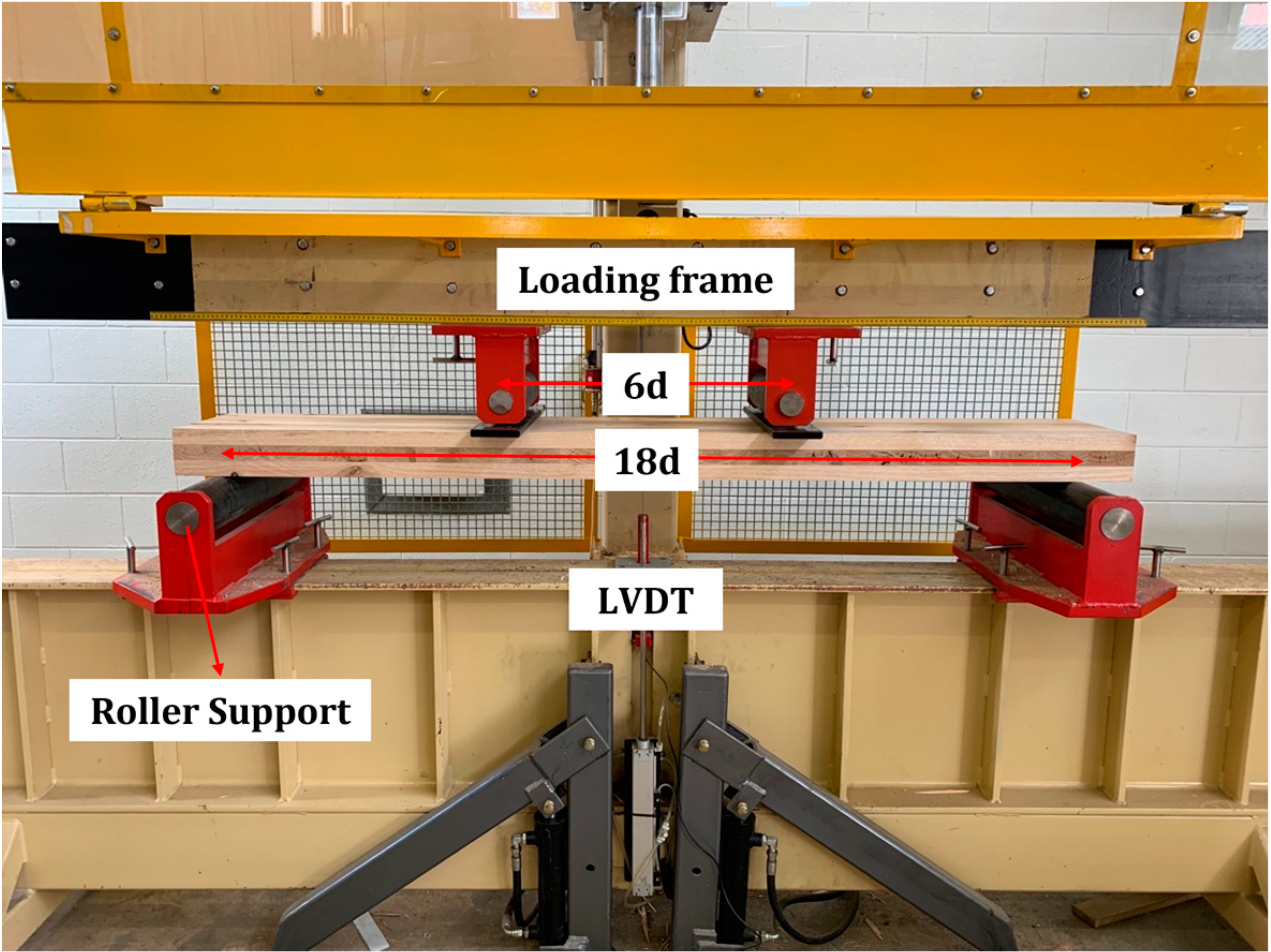
2.3.1. Static Bending Tests

The static non-destructive linear elastic four-point bending tests (Figure 1) in accordance with AS/NZS 4063.1 [37] were performed for two main purposes—one is to obtain the values of the apparent MOE (Equation (1)) and bending stiffness of CLT panels (Equation (2)), and another is to measure the mid-span deflection under serviceability loads.
The experimental bending stiffness was calculated by Equation (2) based on EN 408 [42].
E I g = 3 a L 2 - 4 a 3 48 ( w F - 3 a 5 G b h )
where a is the shear span and equal to 6 times the depth of the panels (mm); L is the support span length of the panels (1800 mm in this case); w is the increment in displacement related to F (mm); F is the increment in load; G is the shear modulus of the panels, which is approximately equal to MOE/16 in this study [18]; b is the width of the panels; and h is the thickness of the panels.
In this study, the displacements during the four-point bending tests were measured globally. Therefore, only global bending stiffness ( E I g ) was considered.
Then, the Shear Analogy method [17,18] was used to predict the effective bending stiffness of the CLT panels based on the MOE values of individual layers, which was firstly presented by Kreuzinger [43]. The effective bending stiffness was calculated using Equation (3):
E I e f f = i = 1 n E i b i h i 3 12 + i = 1 n E i A i z i 2
where Ei is the MOE of the ith layer (MPa), bi is the width of the ith layer (mm), hi is the depth of the ith layer, and zi is the distance from the centroid of each layer to the neutral axis (mm).
Furthermore, the values of the effective bending stiffness were adjusted to the apparent stiffness for the effects of shear deformation using Equation (4):
E I a p p = E I e f f 1 + K s E I e f f G A e f f L 2
where Ks is the factor according to the ratio of the deflection due to bending to the deflection due to shear, which is equal to 12.96 in this study [33,44], and L is the span of the panels. G A e f f was calculated by Equation (5) as:
G A e f f = a 2 [ h i 2 G 1 b + ( i = 2 n - 1 h i G i b ) + ( h n 2 G n b ) ]
where a is the distance between the neutral axes of the outer layers (mm), b is the width of the panels (mm), G i is the shear modulus of the ith layer (MPa), and hi is the thickness of the ith layer (mm).
In addition, three cycles of 130% loading and unloading bending tests were performed using the same setup. The deflection under serviceability loads was measured using an LVDT, located at the mid-span of the panels and measuring the deflection from the bottom. The serviceability loads were defined from AS/NZS 1170.1 [45], which are 1.5 kPa for a residential building, 3 kPa for an office building, and 1 kPa for superimposed dead load in both cases. These loads were uniformly distributed loading (UDL), and from the bending rig, concentrated loads were required. Therefore, Equations (6) and (7) were used to convert the UDL (kPa) to an equivalent force (kN) to be applied in the bending rig:
P L 6 = q L 2 8
P = 3 q L 4
where q is the load combination of superimposed dead load and live load (kN/m), L is the span length of the panels (1.8 m in this case), and P is the experimental four-point bending load (kN).
The total load applied by the testing machine was 1.83 kN. This applied load also ensured that the 1.5 kPa of live load for residential buildings was well exceeded. Then, the deflections of CLT panels determined from these tested were compared to the deflection limit of span/300, which is indicated from AS/NZS 1170.0 [14].
Furthermore, the effective bending stiffness E I e f f and the effective shear stiffness G A e f f determined from the Shear Analogy method were used to predict the total mid-span deflections under the same serviceability loads using Equation (8) [46]:
= 5 384 w L 4 ( E I ) e f f + 1 8 w L 2 G A e f f
where w is the total theoretical applied load (kPa), L is the span (m), E I e f f is the effective bending stiffness (kN·m2), and G A e f f is the effective shear stiffness (kN·m2).

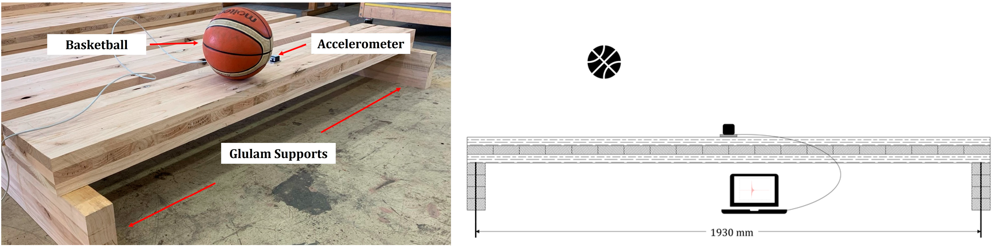
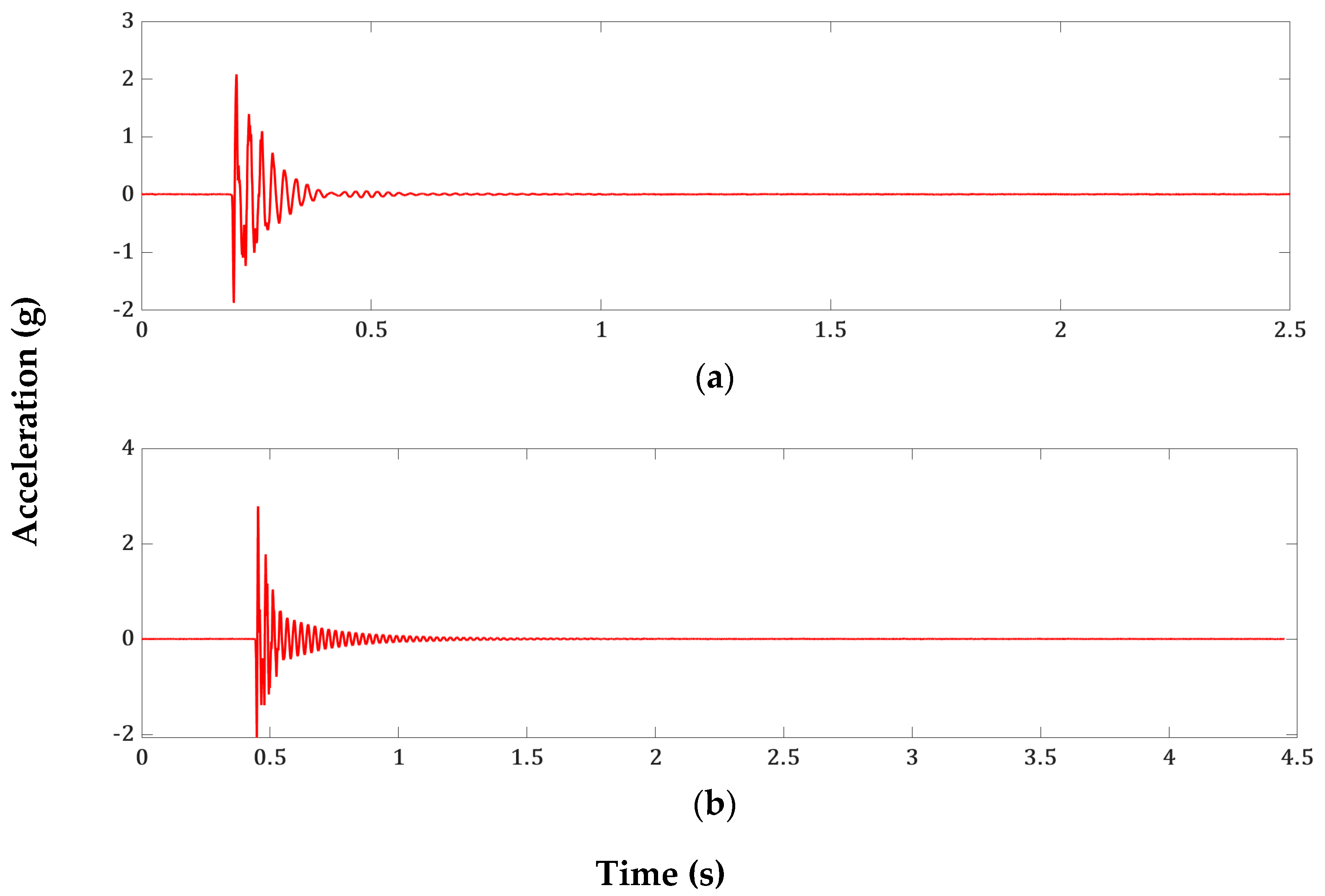
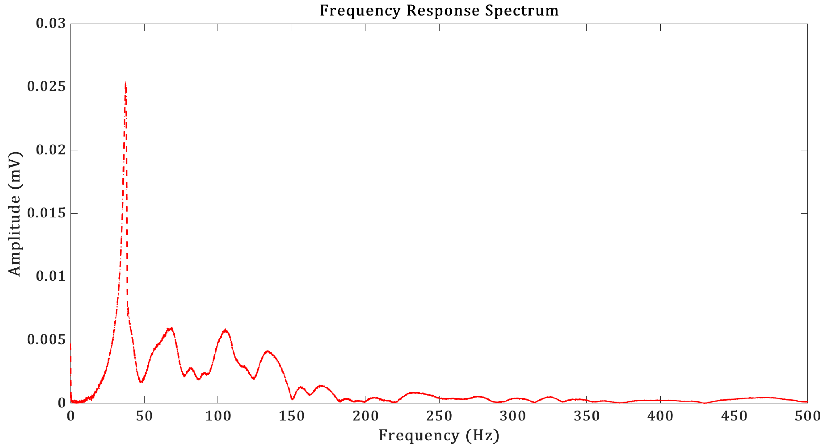
2.3.2. Vibration Tests

The testing method used to determine the dynamic responses of the CLT panels was similar to previous research of Hamilton et al. [47], Taoum et al. [24], and Derikvand et al. [8] using an accelerometer and a basketball. The mid-span vertical acceleration of the panels was measured using a Crossbow CXL04LP3 accelerometer with a sensitivity of 500 ± 25 mV/g (Figure 2). The accelerometer was secured on the top of the panels, and a 630 g basketball dropped from a height of approximately 400 mm was used as the excitation source.
Each CLT panel was excited three times, allowing sufficient elapsed time between excitations to ensure that the previous vibration was sufficiently dampened so as not to affect the response to the following impact. Fast Fourier Transformation (FFT) was used to determine the fundamental natural frequency of the CLT panels taken from the acceleration–time data obtained from the vibration tests. The damping ratio was determined using the following sequence in MATLAB.
Equation (4) assumed the following form for the equation of displacement for a vibrating system with linear stiffness and damping responses [48]:
x = X e - δ ω t sin 1 - δ 2 ω t + φ
where δ is the damping ratio (%), ω is the undamped natural frequency (Hz) (for a lightly damped system, the undamped natural frequency can be assumed to be the same as the damped natural frequency), t is time (s), and X and φ are arbitrary phase and amplitude constants defined by initial conditions.
The magnitude of the oscillations was controlled by the exponential term shown in Equation (10) because the maximum value of the sine term is equal to 1.
y = X e - δ ω t
Hence, the damping ratio was determined by using Equation (11) after differentiating and rearrangement:
δ = - 1 ω d ln y d t 1 ω ln y 1 y 2 t 2 - t 1
where y 1 and y 2 are the amplitudes measured at two times, t 1 and t 2 .
The values of the fundamental natural frequency were then adjusted based on the values of the frequency constant λ1, which were calculated by extrapolating Equation (12) as follows:
f n = λ n π 2 l 2 E I μ
where f n is the undamped natural frequency (Hz) for the nth vibration mode (only the first vibration mode was considered in this study), λ n is the frequency constant, l is the span length (m), E I is the apparent stiffness of the tested panels in the span direction (N·m2), and μ is the mass per meter (kg/m).

3. Results

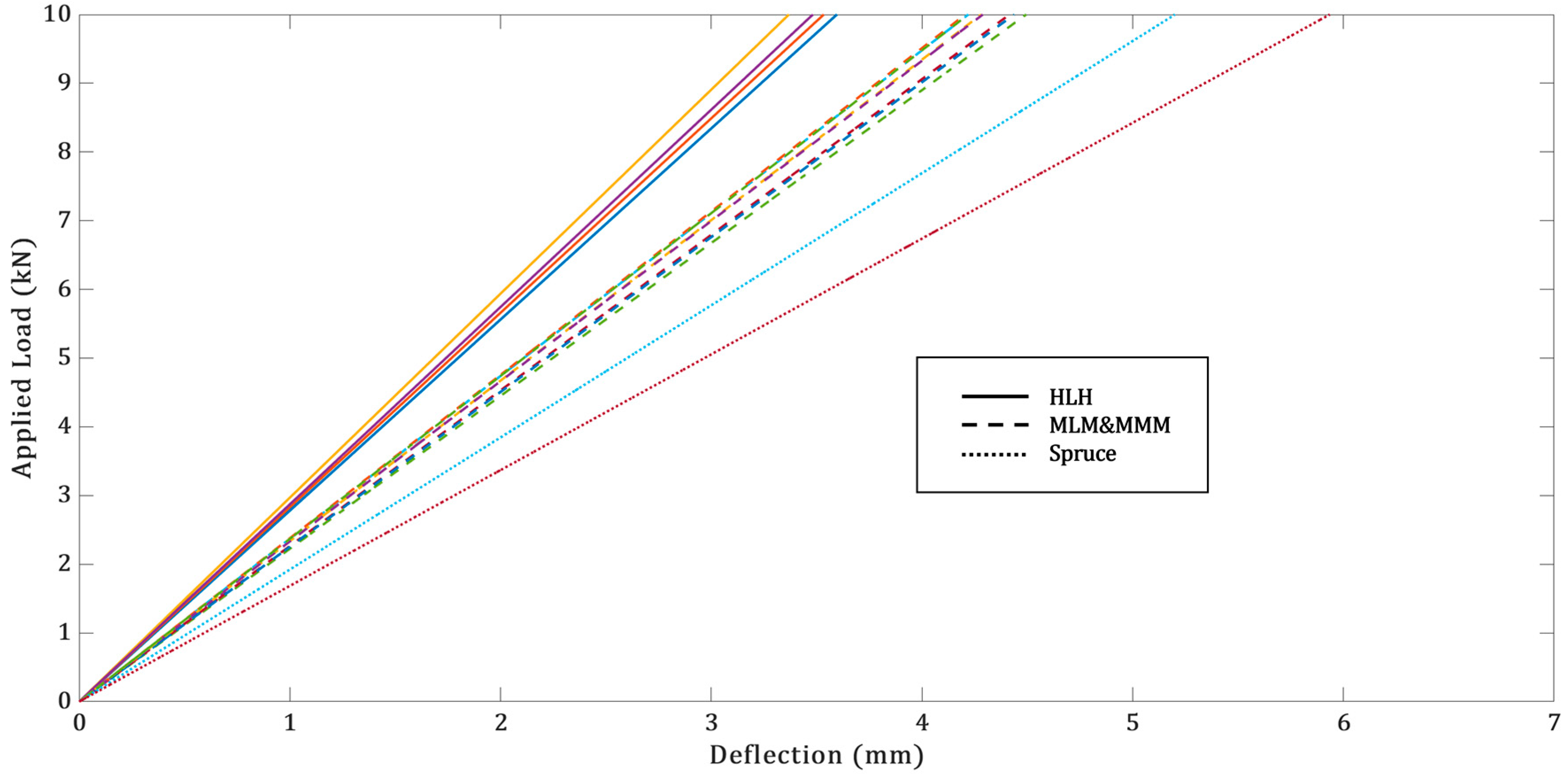
3.1. Experimental and Theoretical Bending Stiffness

Figure 3 shows the load–deflection curves up to 10 kN of applied load. The apparent MOE, experimental bending stiffnesses ( E I and E I g ), effective bending stiffness ( E I e f f ), shear stiffness ( G A e f f ), and apparent bending stiffness ( E I a p p ) are summarised in Table 4. The values of E I were calculated by multiplying the MOE obtained from Equation (1) by the moment of inertia, I (mm4), which was calculated by the following equation:
I = b h 3 12
where b is the width of CLT panels (mm), and h is the thickness of the CLT panels (mm).
The values of the apparent bending stiffness E I a p p are used in the theoretical calculations of the fundamental natural frequency in Section 3.3. It is also worth noting that the theoretical results for Spruce CLT were calculated based on the assigned stiffness properties of strength class C24 as specified in EN 338 [34] for individual boards.

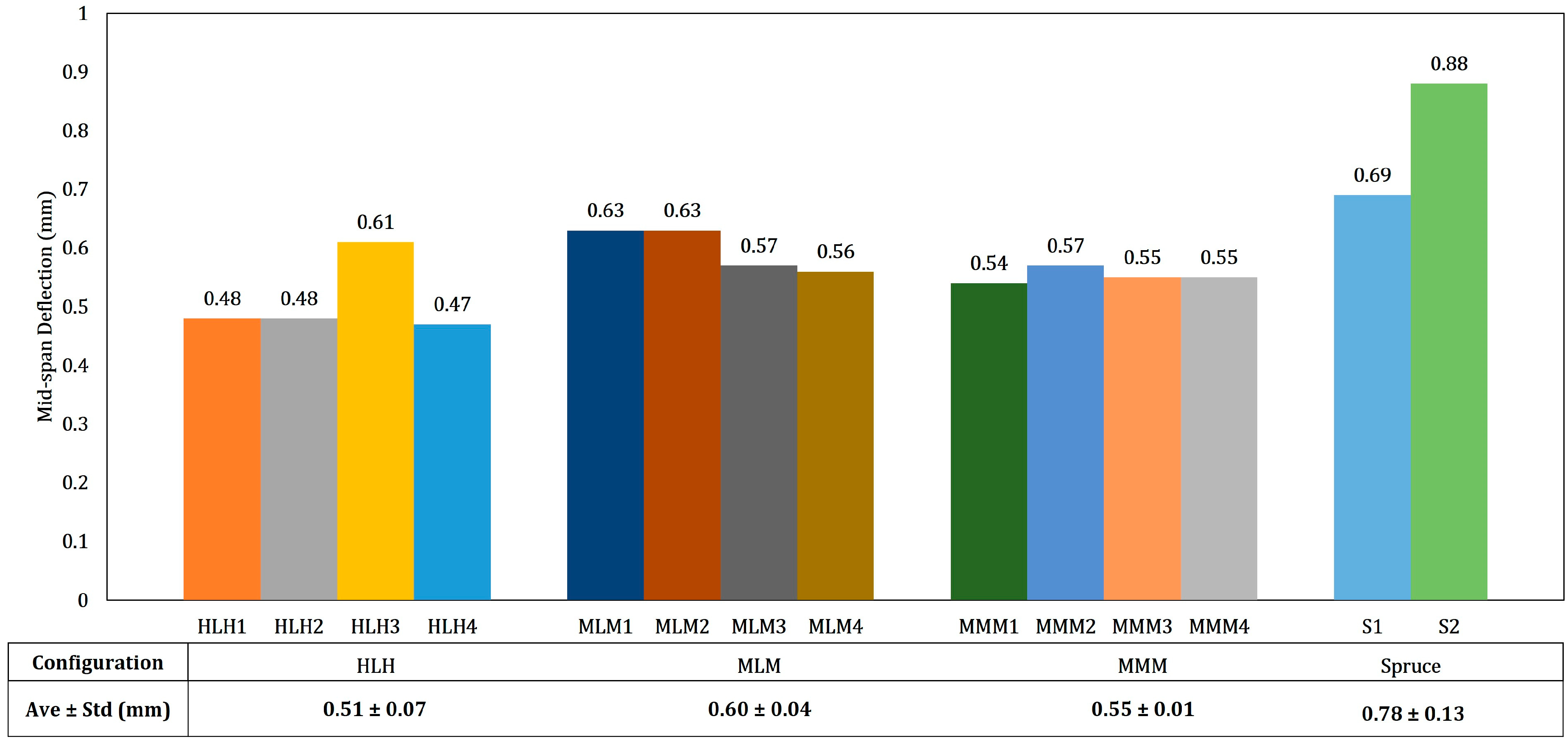
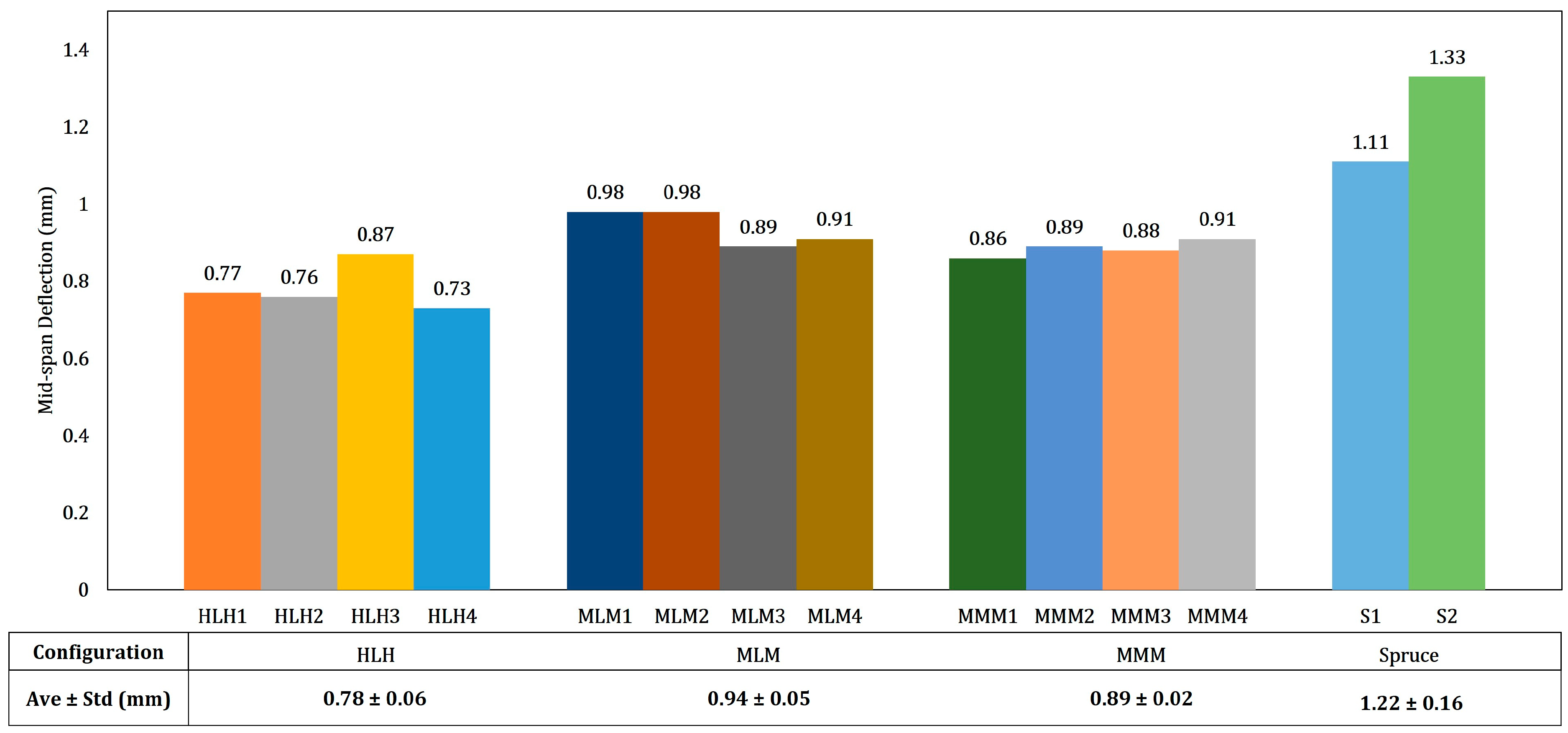
3.2. Mid-Span Deflections under Serviceability Loading

The results of the mid-span deflection under 1.25 kN and 1.83 kN serviceability loads are summarized in Figure 4 and Figure 5, respectively. The results are much lower than the deflection limit (span/300), which is 6 mm in this study.
The comparisons between the experimental and theoretical results are summarized in Table 5.

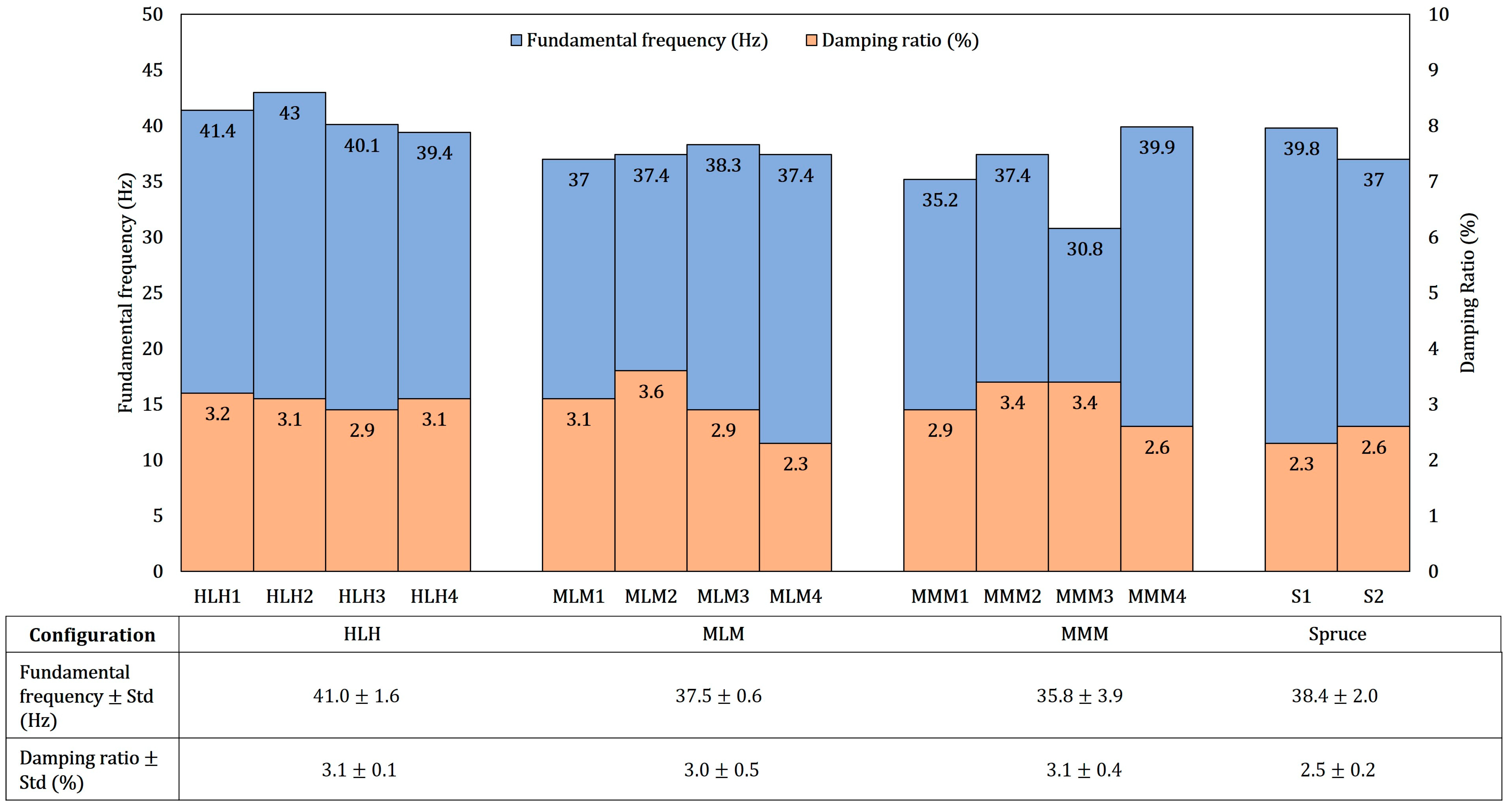
3.3. Dynamic Responses

The typical acceleration–time graphs for CLT panel are shown in Figure 6.
After FFT programming from MATLAB, the results of the fundamental frequency were determined based on the strong peak of the frequency response spectrum. Figure 7 is a typical result of the frequency response spectrum.
The experimental results of the fundamental natural frequency and damping ratio are summarised in Figure 8.
The average values of λ1 calculated by extrapolating Equation (12) are summarized in Table 6.
The average values of λ1 using the apparent bending stiffness (EIapp) from the Shear Analogy method were used to adjust the values of the fundamental natural frequency using Equation (12). The adjusted results are summarised in Table 7.
Then, the values of λ1 and adjusted fundamental frequency were used to calculate the maximum span to comply with a criterion of the first mode vibration frequency above 8 Hz with no furniture or floor coverings. The results are shown in Table 8.

4. Discussion

According to the experimental results of bending stiffness (EIg) (Table 4), using higher-grade timber boards as top and bottom layers can significantly increase the bending stiffness of CLT panels, while using higher-grade boards in crossing layers can only increase the bending stiffness slightly. This phenomenon is also applicable to the results of the apparent MOE. The values of the effective stiffness (EIeff) were slightly higher than the experimental stiffness (EIg) for E. nitens CLT, which has also been demonstrated by Ettelaei et al. [3]. The values of the bending stiffness (EI) determined by multiplying the apparent MOE by the moment of inertia showed a high correlation with the bending stiffness (EIg) determined by Equation (2) according to EN 408 [42]. However, the results from Spruce CLT showed greater variations when comparing the experimental stiffness with the effective stiffness. The reason may be that the used values of MOE for individual spruce boards were based on the manufacturing values, assigned by EN 338:2016 [34], which implies a grading difference between industry and laboratory.
In accordance with the results of the mid-span deflection under serviceability loading, using higher-grade timber boards for the top and bottom layers significantly decreased the total serviceability deflection by around 17% on average through the comparison of HLH and MLM CLT configurations, and using higher-grade timber boards in the crossing layers achieved a decrease of 5–8% of the total serviceability deflection. For E. nitens CLT panels, the experimental deflection results were approximately 11 times and 7 times less than the deflection limit (L/300) under the serviceability loads of 1.25 kN and 1.83 kN, respectively [14]. It is worth mentioning that Spruce CLT panels have the highest deflection under these serviceability loads and have the lowest deflection ratios compared to all E. nitens CLT panels. The comparison between the experimental and theoretical results of the mid-span deflection (Table 5) indicates that Equation (8) could accurately predict the total mid-span deflection of E. nitens CLT panels using the theoretical bending stiffness.
In addition, HLH CLT panels have the highest values of fundamental frequency among all E. nitens CLT, which indicates that the higher MOE timber board as top and bottom layers can upgrade the vibration performance of CLT. However, using higher-grade timber boards (MMM) decreased the values of fundamental frequency by 4.7% compared to MLM CLT, in part due to the slightly higher mass. The population mean of E. nitens CLT (38.1 Hz) had similar values of fundamental frequency to that of Spruce CLT (38.4 Hz). However, the damping ratio of E. nitens CLT is approximately 24% higher than that of Spruce CLT. Ohlsson et al. [49] suggested that the quicker the vibration decay period, the less perceptible it is to humans. Therefore, E. nitens CLT is slightly better than Spruce CLT in terms of the overall vibration performance combining the fundamental frequency and damping ratio. Moreover, based on the Canadian CLT Handbook [17], it is recommended to use a damping ratio of 2% for wood buildings without finish. In this study, all the tested CLT panels were within the acceptable limits. Nevertheless, it is important to keep in mind that damping ratios obtained in laboratory settings are far lower than those that would be obtained in practical applications. This is because installing the system in a real structure would subject it to a considerable increase in energy loss at different kinds of connections. It is challenging to assess this reduction in damping in laboratory setting since the damping is substantially influenced by the manufacturing process such as the quality of workmanship [50] and the additional fitting.
The frequency constants ( λ 1 ) were calculated by extrapolating Equation (12) using the experimental fundamental frequency and the apparent bending stiffness (EIapp). Then, the values of fundamental frequency were adjusted (Table 7) using Equation (12), and the maximum spans to comply with a criterion of the first mode vibration frequency above 8 Hz were determined (Table 8). From the results, HLH CLT can achieve spans up to 4.4 meters, which is 4.8% and 7.3% higher than MLM and MMM CLT, respectively. The population mean of E. nitens CLT has similar results to Spruce CLT (4.2 m).
The results of E. nitens CLT vibration performance from experiments show a certain degree of uncertainty when relating to the stiffness of CLT. According to the previous research [51], the presence of knots would bring uncertainty to the results of frequency. In this study, the E. nitens sawn boards consisted of a large volume of SRCs. Therefore, even though the structural grade (assessed by MOE) was similar for each CLT with the same configuration, inconsistencies existed because of the characteristics of individual panels, which may lead to uncertainties in the vibrational results.

Further Research

When CLT panels are used as flooring, their surfaces are often covered by different finishes such as carpets and engineered wood panels (EWPs). In this study, only the vibration performance of bare CLT panels was considered. However, it is necessary to investigate the effect of using different furnishings on the vibration performance of E. nitens CLT panels due to the additional mass and the likely significant increase in damping. In addition, boundary conditions can largely influence the vibration performance of flooring. It is difficult to simulate the real boundary conditions in a laboratory environment as these are affected by the connection rigidity and the mass and stiffness of the overall structural frame and walls, but meaningful knowledge can be generated through controlling the end restraints of the CLT panels. Therefore, in the following research, these variables will be mainly focused on.

5. Conclusions

The main purpose of this research was to preliminarily investigate the performance of E. nitens CLT panels under serviceability bending loads and vibration effects. Comparison with Spruce CLT panels was also conducted to demonstrate that using fibre-managed E. nitens as feedstocks to manufacture CLT panels is reliable and that they can be used as alternative structural applications. The following conclusions were drawn according to the experimental results.
During the bending tests on E. nitens CLT panels, using higher-grade timber boards in the top and bottom layers could reduce the serviceability deflection by an average of 17%, and using higher-grade timber boards in the crossing layers could reduce the serviceability deflection by 5–8%. Under 1.25 kN and 1.83 kN serviceability loads, the experimental deflections for E. nitens CLT panels were approximately 11 times and 7 times less than the deflection limit (Span/300), respectively. E. nitens CLT panels showed better performance under bending tests compared to Spruce CLT panels, which had higher deflections under serviceability loads and lower deflection ratios.
During the vibration tests on the E. nitens CLT panels, using higher-grade timber boards (HLH CLT) in the top and bottom layers could increase the fundamental natural frequency by about 9.3–14.5% compared to MLM and MMM CLT panels, while using higher-grade timber boards in crossing layers slightly decreased the fundamental natural frequency by about 4.7% compared to MLM and MMM CLT panels. This is in part due to their higher density. All the tested CLT panels possessed much higher fundamental frequencies than the frequency limit (8 Hz) at a span of approximately 2 m. A theoretical method was used to adjust the experimental results and to predict the maximum span in complying with a criterion of the first mode vibration frequency above 8 Hz, showing compliance up to a span of 4.4 m, which is likely to be significantly higher when realistic end constraints are taken into account, but may be reduced again with furnishings. The overall results for E. nitens and Spruce CLT panels were similar.
The damping ratios of E. nitens CLT panels are quite consistent between all the samples, and about 20% higher than the spruce, which would be of significant benefit in attenuating vibrations.
The Shear Analogy method is a reliable theoretical method to predict the serviceability performance of E. nitens CLT panels, including short-term bending and vibration performance.
The overall serviceability performance of E. nitens CLT panels under bending and vibration tests has been proven to be slightly better than strength class C24 Spruce CLT.
The 3-ply CLT experimental data have generated fundamental knowledge for further research. For example, the results of this paper could be used to validate numerical models, and thus to extrapolate the findings to 5- and 7-ply CLT.

Author Contributions

Conceptualization, Y.L. and A.T.; methodology, Y.L. and A.T.; software, Y.L. and A.T.; validation, A.T. and D.H.; formal analysis, Y.L.; investigation, Y.L.; resources, A.T.; data curation, Y.L.; writing—original draft preparation, Y.L.; writing—review and editing, A.T., N.K., A.C. and D.H.; visualization, Y.L.; supervision, A.T., N.K. and A.C.; project administration, A.T. All authors have read and agreed to the published version of the manuscript.

Funding

This research received no external funding.

Data Availability Statement

Not applicable.

Conflicts of Interest

The authors declare no conflict of interest.

References

  1. Pangh, H.; Hosseinabadi, H.Z.; Kotlarewski, N.; Moradpour, P.; Lee, M.; Nolan, G. Flexural performance of cross-laminated timber constructed from fibre-managed plantation eucalyptus. Constr. Build. Mater. 2019, 208, 535–542. [Google Scholar] [CrossRef]
  2. Ettelaei, A.; Taoum, A.; Nolan, G. Rolling shear properties of cross-laminated timber made of fibre-managed plantation eucalyptus under short-span bending. Wood Mater. Sci. Eng. 2021, 17, 744–751. [Google Scholar] [CrossRef]
  3. Ettelaei, A.; Taoum, A.; Shanks, J.; Nolan, G. Evaluation of the bending properties of novel cross-laminated timber with different configurations made of Australian plantation Eucalyptus nitens using experimental and theoretical methods. Structures 2022, 42, 80–90. [Google Scholar] [CrossRef]
  4. Ettelaei, A.; Taoum, A.; Shanks, J.; Nolan, G. Rolling Shear Properties of Cross-Laminated Timber Made from Australian Plantation Eucalyptus nitens under Planar Shear Test. Forests 2022, 13, 84. [Google Scholar] [CrossRef]
  5. Nero, R.; Christopher, P.; Ngo, T. Investigation of rolling shear properties of cross-laminated timber (CLT) and comparison of experimental approaches. Constr. Build. Mater. 2022, 316, 125897. [Google Scholar] [CrossRef]
  6. Derikvand, M.; Nolan, G.; Jiao, H.; Kotlarewski, N. What to do with structurally low-grade wood from Australia’s plantation eucalyptus; building application? BioResources 2017, 12, 4–7. [Google Scholar] [CrossRef] [Green Version]
  7. ABARES. Australian Plantation Statistics and Log Availability Report: October 2021; Australian Bureau of Agricultural and Resource Economics and Sciences: Canberra, Australia, 2021. [Google Scholar] [CrossRef]
  8. Derikvand, M.; Jiao, H.; Kotlarewski, N.; Lee, M.; Chan, A.; Nolan, G. Bending performance of nail-laminated timber constructed of fast-grown plantation eucalypt. Eur. J. Wood Wood Prod. 2019, 77, 421–437. [Google Scholar] [CrossRef]
  9. Derikvand, M.; Kotlarewski, N.; Lee, M.; Jiao, H.; Chan, A.; Nolan, G. Short-term and long-term bending properties of nail-laminated timber constructed of fast-grown plantation eucalypt. Constr. Build. Mater. 2019, 211, 952–964. [Google Scholar] [CrossRef]
  10. Blackburn, D.; Hamilton, M.; Harwood, C.; Innes, T.; Potts, B.; Williams, D. Stiffness and checking of Eucalyptus nitens sawn boards: Genetic variation and potential for genetic improvement. Tree Genet. Genomes 2010, 6, 757–765. [Google Scholar] [CrossRef]
  11. Derikvand, M.; Kotlarewski, N.; Lee, M.; Jiao, H.; Chan, A.; Nolan, G. Visual stress grading of fibre-managed plantation Eucalypt timber for structural building applications. Constr. Build. Mater. 2018, 167, 688–699. [Google Scholar] [CrossRef]
  12. Derikvand, M.; Kotlarewski, N.; Lee, M.; Jiao, H.; Nolan, G. Flexural and visual characteristics of fibre-managed plantation Eucalyptus globulus timber. Wood Mater. Sci. Eng. 2018, 15, 172–181. [Google Scholar] [CrossRef]
  13. McGavin, R.L.; Bailleres, H.; Hamilton, M.; Blackburn, D.; Vega, M.; Ozarska, B. Variation in rotary veneer recovery from Australian plantation Eucalyptus globulus and Eucalyptus nitens. BioResources 2015, 10, 313–329. [Google Scholar] [CrossRef] [Green Version]
  14. AS/NZS 1170.0; Structural Design Actions—General Principles. Standard Australia/Standard New Zealand: Sydney, Australia, 2002.
  15. EN 1995-1-1:2004; Eurocode 5: Design of Timber Structures—Part 1-1: General—Common Rules and Rules for Buildings. European Committee for Standardization (CEN): Brussels, Belgium, 2004.
  16. National Research Council (NRC). National Building Code of Canada; National Research Council (NRC): Ottawa, ON, Canada, 2005. [Google Scholar] [CrossRef]
  17. Karacabeyli, E. CLT Handbook: Cross-Laminated Timber, Canada Edition; FPInnovations: Pointe-Claire, QC, Canada, 2019; ISBN 978-086-488-592-0. [Google Scholar]
  18. Karacabeyli, E.; Douglas, B. CLT Handbook: Cross-Laminated Timber, US Edition; FPInnovations: Pointe-Claire, QC, Canada, 2013; ISBN 978-086-488-553-1. [Google Scholar]
  19. Gustafsson, A.; Crocetti, R.; Just, A.; Landel, P.; Olsson, J.; Pousette, A.; Silfverhielm, M.; Östman, B. The CLT Handbook: CLT Structures—Facts and Planning; Swedish Wood: Stockholm, Sweden, 2019; ISBN 978-919-832-144-3. [Google Scholar]
  20. Jeleč, M.; Rajčić, V. Cross-laminated timber (CLT)—A state of the art report. Građevinar 2018, 70, 75–95. [Google Scholar] [CrossRef] [Green Version]
  21. Pavic, A.; Reynolds, P. Vibration serviceability of long-span concrete building floors. Part 1: Review of background information. Shock. Vib. Dig. 2002, 34, 191–211. [Google Scholar]
  22. Ohlsson, S.V. Serviceability criteria–especially floor vibration criteria. In Proceedings of the 1991 International Timber Engineering Conference, London, UK, 2–5 September 1991; pp. 1.58–1.65. [Google Scholar]
  23. Hassan, O.A.; Girhammar, U.A. Assessment of footfall-induced vibrations in timber and lightweight composite floors. Int. J. Struct. Stab. Dyn. 2013, 13, 1350015. [Google Scholar] [CrossRef]
  24. Taoum, A.; Jiao, H.; Holloway, D.; Shanks, J. Behaviour of locally post-tensioned nail laminated high mass floor panels under serviceability loads. Aust. J. Struct. Eng. 2019, 20, 115–123. [Google Scholar] [CrossRef]
  25. Murray, T.; Allen, D.; Ungar, E. Floor Vibrations due to Human Activity; American Institute of Steel Construction, Inc.: Reston, VA, USA, 1997. [Google Scholar]
  26. Labonnote, N.; Rønnquist, A.; Malo, K.A. Prediction of material damping in timber floors, and subsequent evaluation of structural damping. Mater. Struct. 2015, 48, 1965–1975. [Google Scholar] [CrossRef]
  27. Bernard, E.S. Dynamic serviceability in lightweight engineered timber floors. J. Struct. Eng. 2008, 134, 258–268. [Google Scholar] [CrossRef]
  28. Jarnerö, K.; Brandt, A.; Olsson, A. Vibration properties of a timber floor assessed in laboratory and during construction. Eng. Struct. 2015, 82, 44–54. [Google Scholar] [CrossRef]
  29. Huang, H.; Gao, Y.; Chang, W.-S. Human-induced vibration of cross-laminated timber (CLT) floor under different boundary conditions. Eng. Struct. 2020, 204, 110016. [Google Scholar] [CrossRef]
  30. Wang, C.; Chang, W.-S.; Yan, W.; Huang, H. Predicting the human-induced vibration of cross laminated timber floor under multi-person loadings. Structures 2021, 29, 65–78. [Google Scholar] [CrossRef]
  31. Weckendorf, J.; Zhang, B.; Kermani, A.; Reid, D. Assessment of vibrational performance of timber floors. In Proceedings of the World Conference on Timber Engineering (WCTE), Portland, OR, USA, 6–10 August 2006. [Google Scholar]
  32. Hu, L. Serviceability of next generation wood buildings: Laboratory study of vibration performance of cross-laminated-timber (CLT) floors. In Project 301006159: Report 2012/13; FPInnovations: Sainte Foy, QC, Canada, 2013. [Google Scholar]
  33. Crovella, P.; Shahhosseini, S. Predicting the Strength and Serviceability Performance of Cross-laminated Timber (CLT) Panels Fabricated with High-Density Hardwood. In Proceedings of the World Conference on Timber Engineering (WCTE), Santiago, Chile, 9–12 August 2021. [Google Scholar]
  34. EN 338:2016; Structural Timber—Strength Classes. European Committee for Standardization (CEN): Brussels, Belgium, 2016.
  35. AS1080.1; Timber—Methods of Test Moisture Content. Standard Australia: Sydney, Australia, 2012.
  36. AS 1080.3; Timber—Methods of Test Density. Standard Australia: Sydney, Australia, 2000.
  37. AS/NZS 4063.1; Characterisation of structural timber Test methods. Standard Australia/Standard New Zealand: Sydney, Australia, 2010.
  38. Samson, M. Potential of finger-joined lumber for machine stress-rated lumber grades. For. Prod. J. 1985, 35, 20–24. [Google Scholar]
  39. Kutscha, N.; Caster, R.W. Factors affecting the bond quality of hem-fir finger-joints. For. Prod. J. 1987, 37, 43–48. [Google Scholar]
  40. Fisette, P.; Rice, W. An analysis of structural finger-joints made from two northeastern species. For. Prod. J. USA 1988, 38, 40–44. [Google Scholar]
  41. Bender, D.; Burk, A.; Taylor, S.; Hooper, J. Predicting localized MOE and tensile strength in solid and finger-jointed laminating lumber using longitudinal stress waves. For. Prod. J. 1990, 40, 45–47. [Google Scholar]
  42. EN 408:2010; Timber Structures—Structural Timber and Glued Laminated Timber—Determination of Some Physical and Mechanical Properties. European Committee for Standardization (CEN): Brussels, Belgium, 2010.
  43. Kreuzinger, H. Platten, Scheiben und Schalen–ein Berechnungsmodell für gängige statikprogramme. Bau. Mit Holz 1999, 1, 34–39. [Google Scholar]
  44. Crovella, P.; Smith, W.; Bartczak, J. Experimental verification of shear analogy approach to predict bending stiffness for softwood and hardwood cross-laminated timber panels. Constr. Build. Mater. 2019, 229, 116895. [Google Scholar] [CrossRef]
  45. AS/NZS 1170.1; Structural Design Actions—Part 1: Permanent, Imposed and Other Actions. Standard Australia/Standard New Zealand: Sydney, Australia, 2002.
  46. CSA O86:19; Engineering Design in Wood. National Standard of Canada: Ottawa, ON, Canada, 2021.
  47. Hamilton, J. Use of low grade timber in residential flooring systems. Bachelor’s Thesis, University of Tasmania, Hobart, Australia, 2014. [Google Scholar]
  48. Thomson, W.T. Theory of vibration with applications, 5th ed.; William, T., Thomson, M.D.D., Eds.; Prentice Hall: Hoboken, NJ, USA, 1998. [Google Scholar]
  49. Ohlsson, S.V. Floor Vibrations and Human Discomfort; Chalmers University of Technology, Division of Steel and Timber Structures: Göteborg, Sweden, 1982. [Google Scholar]
  50. Dolan, J.; Murray, T.; Johnson, J.; Runte, D.; Shue, B. Preventing annoying wood floor vibrations. J. Struct. Eng. 1999, 125, 19–24. [Google Scholar] [CrossRef]
  51. García, D.A.; Sampaio, R.; Rosales, M.B. Vibrational problems of timber beams with knots considering uncertainties. J. Braz. Soc. Mech. Sci. Eng. 2016, 38, 2661–2673. [Google Scholar] [CrossRef]
Figure 1. Setup of the static bending test.
Buildings 13 00245 g001
Figure 2. Setup of the vibration test.
Buildings 13 00245 g002
Figure 3. Load–deflection curves.
Buildings 13 00245 g003
Figure 4. Test results of the mid-span deflection under 1.25 kN of serviceability load.
Buildings 13 00245 g004
Figure 5. Test results of the mid-span deflection under 1.83 kN of serviceability load.
Buildings 13 00245 g005
Figure 6. Typical acceleration–time history plots for (a) HLH4; (b) MLM4.
Buildings 13 00245 g006
Figure 7. Typical frequency response spectrum for MLM4.
Buildings 13 00245 g007
Figure 8. Experimental results of the fundamental frequency and damping ratio.
Buildings 13 00245 g008
Table 1. Test results of the average moisture content and density for E. nitens.
Eucalyptus nitens Boards
Mean   density   ρ w ± StdDev (kg/m3)517.5 ± 45.2
Mean   density   at   12 %   moisture   content ,   ρ 12 ± StdDev (kg/m3)524.0 ± 45.7
Mean moisture content, MC ± StdDev (%)9.7% ± 0.4
Table 2. Test results of the average MOE for E. nitens.
GroupNameMOE (GPa) ± StdDev
1High13.1 ± 0.81
2Medium10.6 ± 0.67
3Low8.3 ± 0.17
Table 3. CLT configurations.
SpeciesPanel CodeLamination Grade from Top to BottomAverage MOEs of Individual Layers (GPa)
E. nitensHLH1High
Low
High
13.2
8.4
13.2
HLH2
HLH3
HLH4
MLM1Medium
Low
Medium
10.6
8.4
10.6
MLM2
MLM3
MLM4
MMM1Medium
Medium
Medium
10.6
10.6
10.6
MMM2
MMM3
MMM4
SpruceS1Strength Class C24 1
S2
1 Based on European Standard EN 338:2016 [34].
Table 4. Experimental and theoretical bending stiffnesses.
SpeciesConfigurationApparent MOE (GPa) E I (N·mm2 × 1011) E I g (N·mm2 × 1011) E I e f f (N·mm2 × 1011) G A e f f (N × 106) E I a p p (N·mm2 × 1011)
Equations(1)MOE × I(2)(3)(5)(4)
E. nitensHLH111.32.902.933.061.951.88
HLH210.92.812.833.111.951.90
HLH311.73.003.033.071.951.88
HLH411.52.962.993.101.951.90
MLM19.02.332.322.481.921.63
MLM29.72.502.502.471.921.63
MLM39.12.332.332.481.921.63
MLM49.02.312.312.491.921.64
MMM19.72.492.492.492.391.76
MMM29.42.422.422.482.391.75
MMM39.32.392.392.472.391.75
MMM49.52.462.452.492.391.75
SpruceS18.32.011.962.572.481.82
S27.51.811.78
Table 5. Comparisons of the experimental and theoretical results.
Configuration1.25 kN Serviceability Load1.83 kN Serviceability Load
Experimental ResultsTheoretical ResultsVAR (%)Experimental ResultsTheoretical ResultsVAR (%)
HLH0.510.521.960.780.791.28
MLM0.600.611.670.940.92−2.13
MMM0.550.585.450.890.87−2.25
Spruce0.780.55−29.51.220.84−31.15
Table 6. Average values of λ1.
SpeciesConfiguration E I a p p (N·mm2 × 1011) μ (kg/m)λ1
E. nitensHLH1.8912.60.79
MLM1.6311.80.76
MMM1.7512.00.70
SpruceS1.8210.20.68
Table 7. Adjusted results of the fundamental natural frequency.
SpeciesConfigurationExperimental Results (Hz)Theoretical Results (Hz)Variations (%)
E. nitensHLH41.040.8−0.5
MLM37.537.8−0.8
MMM35.835.7−0.3
SpruceS38.438.4-
Table 8. Comparison of the maximum spans between E. nitens and Spruce CLT panels.
SpeciesConfigurationMaximum Span (m)Addition Length Compared to Spruce CLT (%)
E. nitensHLH4.44.8
MLM4.20.0
MMM4.1−0.2
SpruceS4.2-
Disclaimer/Publisher’s Note: The statements, opinions and data contained in all publications are solely those of the individual author(s) and contributor(s) and not of MDPI and/or the editor(s). MDPI and/or the editor(s) disclaim responsibility for any injury to people or property resulting from any ideas, methods, instructions or products referred to in the content.

