

An Integrated Workflow for Designing and Fabricating Multi-Functional Building Components through Additive Manufacturing with Clay

Department of Architectural Engineering and Technology, Faculty of Architecture and the Built Environment, Delft University of Technology, 2628 BL Delft, The Netherlands
*
Author to whom correspondence should be addressed.
Buildings 2023, 13(11), 2676; https://doi.org/10.3390/buildings13112676
Submission received: 20 August 2023
/
Revised: 16 October 2023
/
Accepted: 21 October 2023
/
Published: 24 October 2023
(This article belongs to the Special Issue Advances in Additive Manufacturing and Construction 4.0)
Abstract
:This article presents a project that explores the potential of Additive Manufacturing (AM) for designing and fabricating multi-functional building components for improved climate performance. In this project, an innovative façade wall design was developed by using a computational method in an attempt to integrate a displacement ventilation system into the wall. A robotic AM solution is integrated into the workflow as a potentially feasible fabrication method for the resulting wall design with an intricate geometry. Clay is proposed as the AM material, being a potential low-carbon building material. To this end, a material exploration of clay was conducted to develop an appropriate composite for AM. A displacement ventilation system was developed to achieve better indoor air quality by using a Computational Fluid Dynamics (CFD) model. Subsequently, an AM solution was integrated into the workflow to automate the fabrication phase. Finally, a partial prototype of the design was made through AM with clay to demonstrate the feasibility and observe the material qualities of the final product. The proposed workflow proves applicable, highlighting directions for future research.
1. Introduction
This article presents a project that explores the potential of Additive Manufacturing (AM) for designing and fabricating multi-functional building components for improved climate performance by using a low-carbon building material such as clay. It is developed on the premise that AM can simplify the production of complex building components by eliminating the need for external infrastructure required for climate-related building performance such as Heating, Ventilation, and Air Conditioning (HVAC) systems, and allowing new design approaches that consider them as integrated parts of the building components. Additionally, an integrated computational design process can seamlessly blend the design, performance analysis, optimization, and fabrication phases within an integral workflow, allowing all phases to inform each other.
We propose an AM design concept that aims to optimize thermal performance and integrate ventilation channels inside a wall. Computational Fluid Dynamics (CFD) is used as a tool to maximize the dispersion of ventilation air over a larger air supply area while minimizing the pressure loss of the channel morphology. CFD for predicting the performance of building ventilation duct elements has been used by many others (e.g., [1,2]). Implementing ventilation ducts within façade elements was explored in research [3] towards activating the thermal mass of concrete in building elements. It explores how AM could help in achieving better thermal performance. This project adopts a similar strategy of rethinking the building façade or walls to have a bigger role in building physics and performance. On the other hand, real-life fabrication or its integrality with the AM workflow from design to fabrication was not considered. In other fields, CFD as a tool for optimizing the pressure loss in manifolds for combustion engines has been studied in a number of projects (e.g., [4,5,6]). Another area of research that focused on optimizing the ventilation system and applied this to a methodology for AM was inspired by termite mounds [7]. However, no tests or CFD analyses were performed in this study. To our knowledge, using CFD for optimizing a smooth non-manifold ventilation distribution system within building components has not been performed before.
In this research, we propose an integral approach for the design and manufacturing of such a building component, a façade wall in which the ventilation distribution system is integrated. This integration results in a complex design with intricate geometric qualities. Traditional manufacturing techniques cannot effectively answer the need for producing such complex forms in an efficient, affordable, and sustainable way. On the other hand, AM is considered an enabling technology where such complexity is needed.
In the Architecture, Engineering, and Construction (AEC) industry, AM can allow automated production processes, integrating the entire workflow from the initial concept design to the final fabrication stage. The main promises of AM for AEC also appear as the production of intricate geometries, the potential to reduce material waste, and experimentation with novel materials. The growing interest in AM in the industry is encouraging both the use of novel materials and novel experimentation with known materials, for the fabrication of building components. In this regard, the use of clay is being increasingly revisited by the industry, as it potentially can provide environmentally friendly and affordable solutions.
The international standard ISO/ASTM 52900:2001 defines AM as the general term for the process of joining materials to make parts from 3D model data, usually layer upon layer [8]. There are several AM methods, such as Fused Deposition Modelling (FDM), Selective Laser Sintering (SLS), Selective Laser Melting (SLM), Liquid Binding in Three-Dimensional Printing (3DP), Inkjet Printing, Contour Crafting, Stereolithography, Direct Energy Deposition (DED), or Laminated Object Manufacturing (LOM) [9]. This research specifically explores extrusion-based AM, which is suggested as a method that offers greater design freedom, larger building volumes, and more cost-efficient production than liquid- and powder-based AM processes [10]. In extrusion-based AM, the material is selectively dispensed through a nozzle or orifice [11] to create a solid object in successive layers. Several materials that have appropriate viscosity for extrusion and hardening properties after extrusion can be used in this method. In the AEC industry, one of the most commonly used materials in this method is concrete. Extrusion-based AM of concrete occurs when “printable” cement-based material is extruded through nozzles made of different sizes to form a layered structure [12]. Similarly, in this research, clay is explored as a potentially sustainable and effective building material in large-scale extrusion-based AM applications for building constructions.
Several review articles (e.g., [13,14,15,16,17,18,19]) explore the opportunities and challenges of AM in the AEC industry. More specifically, a critical review article analyzes the state-of-the-art research on digital earth construction and suggests that development of the digital earth construction explicates the potential of earth construction and expands the scope of digital manufacturing in construction beyond cement-based materials that are environmentally less friendly [20]. A perspective article argues that the construction industry needs to transform to combat environmental issues by using modified naturally sourced materials, and suggests a new construction paradigm centered on these materials [21]. Another research suggests that AM with clay has several benefits for the construction industry; such as good mechanical strength, low material cost and environmental impact, and recyclability of the raw material [22]. Similarly, another study argues that AM with mud has the potential to reintroduce traditional materials within our contemporary design culture, answering the current demands of sustainability, energy efficiency, and cost in construction [23].
One of the most known commercial applications of architectural AM with clay is the TECLA House built by the WASP system [24]. One of the research projects in this field introduces a novel approach to clay bricks for construction, focusing on complex internal geometries based on minimal surfaces by using AM [25]. The Biodigital Clay Bricks project aims to minimize material consumption and processing while maintaining functional design through AM [26]. Another research presents a parametric design approach for AM using earth- and clay-based materials and evaluates the outputs of the developed algorithm for controlling the design and manufacturing processes [27]. The Saltygloo, MUD Frontiers, Bloom, and the Cabin of 3D Printed Curiosities projects explore how salt, soil, cement, and chardonnay can be used in construction applications [28]. The effects of AM on the mechanical behavior of stoneware bricks are presented in another research paper [29].
Following the literature review, and the recent developments in industrial applications and scientific studies, this research explores the usability of clay in AM for producing a ventilation-integrated façade wall that has a complex geometry. To this end, it studies the material qualities and behavior during and after manufacturing, and the ventilation performance concerning morphology design. The results are demonstrated through a proof of concept that integrates the ventilation distribution and supply system into the design of the wall, which results in a highly intricate geometric design that is too challenging to fabricate by using common traditional building methods. This is the point where AM is considered a potentially feasible manufacturing solution that can facilitate the production of the wall as a single-material multi-functional building component. To this end, a complete workflow was developed that integrates the design, analysis, and optimization of the geometry as well as the automation of the fabrication through AM. By using this workflow, a concept design was developed and then it was partially prototyped by using clay through robotic AM.
2. Design of the Displacement Ventilation
Displacement ventilation was chosen as the system to be integrated within the research prototype, which has its advantages as well as limitations. Figure 1 illustrates the main principles of Mixing Ventilation Systems (left) and Displacement Ventilation Systems (right). The advantages of Displacement Ventilation can be summarized in four points. Firstly, better Indoor Air Quality (IAQ) can be achieved compared to conventional mixing systems. Due to the buoyancy forces of the air supply, it is assumed that the contaminated air will be exhausted from the higher returns easily. Secondly, it requires lower air-supply velocities which enable reduced fan energy consumption [30]. Thirdly, higher chiller efficiency is achieved by the relatively higher temperature of the return air and lower supply temperature. Finally, a lower air-supply velocity yields lower noise levels [31]. On the other hand, the limitations of the system affect and are affected by the spatial characteristics, such as the room height being higher than about 2.8 m and the room depth being smaller than 8–9 m to allow the ventilation air to reach the entire space. These limitations were considered in the design of a hypothetical case study for prototyping.
2.1. Case Study: Room Dimensioning
The city of Seville in Spain was chosen as the location for the case study. According to the Köppen climate classification system, it has a Mediterranean hot dry summer climate “Csa” [32]. The weather data were used in the calculations and simulation for the cooling loads of an office room, which is the chosen case study in this research. Figure 2 shows the layout of the office space that is used as the case study. As shown in this figure, the open floor plan of an office building is assumed to have a core where the building services are located. Out from that core, air ventilation ducts are distributed over the office rooms. In our design, the proposed wall is supposed to act both as a supply duct and a grille. The corner room of the floor plan was chosen with a floor surface area of 30 m2, and an occupation of 3 persons.
2.2. Case Study: Duct Dimensioning
For low-pressure ventilation systems, the equal friction method is advised by the standard [33]. In this method, the pressure drop per unit length is the same in all branches. The resultant duct diameter of this method and the permissible pressure drop per unit length are considered as criteria for verifying a proposed morphology of a designed façade wall and its applicability.
Table 1 summarizes the values used as criteria for the façade morphology design and duct dimensioning. The required cooling was calculated using a simulation model in Design Builder 5.5.2.007 software. In this simulation, the U-value of the external façade was 0.73 W/m2K, which is within the recommended range for new buildings in the Spanish code for the Seville region [34]. At a room temperature of 26 °C, the required cooling load was estimated at 1.0 kW. With a ventilation supply temperature of 18 °C, this corresponds to an airflow rate of 100 dm3/s. Eventually, a duct diameter of 0.2 m was used as a base and a starting point to generate the morphology that sprang off into smaller branches, while the total pressure drop was used to verify each variation generated for the morphology using CFD modeling. For traditional air ducts, the pressure loss is 0.6 Pa/m.
2.3. Façade Morphology Generation
The designed wall is a non-structural façade unit, which on a building scale may constitute a connected system of ventilation ducts. A façade unit is implemented and created by and within the printing infill. To avoid high-pressure drops and inconsistent ventilation supply rate over the façade, the wall is considered to be connected by a main duct that runs horizontally at the top of the façade on each floor. This main duct supplies the air to the façade units at one supply point, from which the air is further distributed downwards to the lower supply openings in the façade surface.
Figure 3 shows the concept initial design (left) and the improved design (right) of the wall with ventilation. In the initial design, multiple façade units can be connected in the horizontal direction to allow a continuous air supply that goes through all of the units. This design is expected to cause more pressure losses throughout the whole façade. In the improved design, each façade unit can be attached to the main supply duct independently, allowing air distribution from top to bottom in each unit. This design version is expected to perform more efficiently.
Six design principles were implemented to generate the duct geometry and morphology. Firstly, the air direction in the main supply channel is vertically downward, allowing the air to flow smoothly and in an equally distributed manner towards the outlet openings at lower positions. Secondly, the printing orientation of the unit resting on the long edge reduces the risk of buckling due to the material accumulation as well as providing the support layers for the overhanging air outlets during printing. In Figure 4, the effects of printing direction are shown as horizontal (A) and vertical (B), regarding the orientation of the air supply ducts. The horizontal direction results in more overhangs with less successive materials. The vertical direction results in more support for overhangs. Therefore, manufacturing the wall vertically is considered to be more stable.
Thirdly, the shortest walk between the inlet supply point to the outlet supply points is found through the A* Algorithm, which is a common path-finding topology algorithm in computer science. This shortest network reduces the total pressure loss from the inlet to the outlet as well as the material required for the printing. Figure 5 illustrates the design of the duct morphology, which is based on four principles: Figure 5A achieving the shortest network between inlet and outlet points, Figure 5B having outlet diameters smaller than inlet diameters, Figure 5C providing smooth corners, and Figure 5D directing the overhang outlets to the interior. Next, an inlet-to-outlet diameter ratio was chosen to have control over the air distribution. Furthermore, the geometry edges are smoothed to eliminate sudden changes to reduce frictional losses. Eventually, the outlet openings are overhung from the interior wall surface which better directs the air towards the floor than a flushed, flat opening.
Based on the above-described principles, different geometries and morphologies were generated which were further analyzed using CFD.
2.4. Ventilation-System Verification
The geometric model of the façade air channel system was created in Grasshopper 1.0 and Rhino 6.0 software, and exported as a mesh model for further analysis to Ansys Fluent CFD 19.0 software. In the steady-state k-ε CFD model, an inlet air velocity of 3 m/s was used. The surface roughness will affect the flow and frictional losses, but in this case, the influence of the duct’s morphology is more prominent in defining the flow characteristics. We used smooth inner walls in the simulation.
Numerically extracted results were the pressure drop, calculated as the difference between the average total pressure between the inlet and the outlets, which was compared against the design criterion. In addition, streamlines and sectional contours were inspected to identify positions where the flow through the overall geometry may be suboptimal. This helped in noticing any unnecessary outlet branches, locations with backflow due to the sudden changes, or overly direct connections from inlet to outlets creating an uneven distribution of the supply flow.
From the evaluation of these trials, we came to the following basic design principles illustrated in Figure 6:
- Exclude branches that have an angle between 10 and 25 degrees. This seems counterintuitive, but branches within that range are relatively inefficient in distributing the air over a wider area (Figure 6A).
- Reduce direct inlet-to-outlet flow paths to ensure better distribution of the air over the branches and outlets of the wall (Figure 6B).
- Avoid cavities (main nodes) that distribute to more than four branches. This reduces backflows and hence pressure losses (Figure 6C).
- Reduce the number of distribution nodes in the main branches.
Based on these principles, four different geometries, shown in Figure 7, were generated and their performance was analyzed in terms of air distribution and pressure-drop behavior. G1 exhibits inefficient branching patterns characterized by angles ranging from 10 to 25 degrees. G2 illustrates the potential for inefficient distribution resulting from direct inlet-to-outlet connections. G3 illustrates the impact of wide distribution nodes on the overall distribution efficiency. G4 incorporated the design principles derived from previous analyses, yielding better outcomes. The main findings of the CFD analysis on these four design variations are summarized in Table 2. Calculated pressure losses are about 0.8 Pa/m, which is only slightly higher compared to a smooth 0.2 m diameter duct. Geometry G4 was chosen for 3D printing the prototype due to its more efficient and maximally even air distribution over the wall surface.
3. Design for Additive Manufacturing
Figure 8 shows the complete design of the wall (350 × 500 cm) with the integrated ventilation-distribution network in the wall. The image also indicates the part (90 × 70 cm) of this wall which was considered for prototyping through AM. This part includes three main design elements of the wall, such as outlets, overhangs, and inner ducts, as seen in Figure 9. The prototype was rotated 180 degrees from its original orientation for AM as seen in the same figure. This ensured that the outlets and overhangs were supported by their bottom layers while manufacturing the prototype.
The infilling, meant to generate the cavity volume between the two wall surfaces, was not developed through standard slicing software. Instead, it was developed in a custom way, ensuring two principles were upheld: providing structural stability and integrating thermal performance.
3.1. Principle 1: Structural Stability
The design of the infilling had to consider three main forces, as shown in Figure 10:
- Forces from the self-weight of the shell (wall outer surface) can cause buckling.
- Forces from self-weight of the inner air ducts, especially when they cantilever.
- Lateral outdoor forces such as wind and earthquakes.
Different infill-pattern design options, shown in Figure 11, were considered for the design of the infilling pattern for structural stability, concerning the shell (outer surface) thickness. The figure shows: Figure 11A the boundary without infilling, Figure 11B the linear infilling design using projected points, Figure 11C the linear infilling design using the duct normals, and Figure 11D the cubic infilling design using intersecting straight lines as a weaving pattern. The Projected Points (Figure 11B) pattern supports only the lateral forces in the direction of the length and neglects the other forces. The Duct Normals (Figure 11C) pattern supports the lateral forces on the length of the duct. However, it does not provide enough support for the forces that are in the direction of the width. Eventually, the Weaving Pattern (Figure 11D) stood out as the most suitable pattern to support the mentioned three forces and achieve structural stability.
Another aspect in regards to structural stability relates to the overhang angles in the object. Our experiments have indicated that the overhang angles should be kept below 60° for desired structural stability during manufacturing.
3.2. Principle 2: Thermal Performance
The infilling pattern aimed at reducing the heat transmittance through the wall, as it should achieve a U-value of 0.73 W/m2K. We analyzed the effects of different infill pattern design options on thermal transmittance using Therm 7.6 thermal analysis software. Figure 12 shows how U and R-values change concerning (Figure 12A) solid and void volumes within the wall, (Figure 12B) infilling, and (Figure 12C) cavities. Solid infill provides better insulation compared to larger air cavities, and increasing its thickness enhances thermal resistivity or reduces transmittance. The designed weaving infill already features a low U-value, thanks to the reduced cavity size formed by intersections and the large material area it offers. Finally, parallel barriers containing smaller and numerous air cavities align with the design criteria for a low U-value.
It was thus observed that optimal performance is obtained through a geometry with many voids perpendicular to the heat-transfer direction. For the final design, it was therefore decided to mainly add horizontal barriers, in combination with the Weaving Pattern, to the infilling design (Figure 13).
3.3. Toolpath within Parametric Model
A parametric model was developed in Grasshopper 1.0 to slice the wall geometry and generate the printing layers as continuous curves to be used as a robotic toolpath. The printing layers can be adjusted through variables in the parametric model, to adjust the thermal and structural performances concerning the principles explained above. Figure 14 shows three design options with different infilling densities resulting in different thermal buffer amounts, cavity-width thicknesses, and structural support nodes. Eventually, the model exports the curves into RoboDK 3.8 software, which was used to generate the robot simulation and program.
4. Material Explorations
4.1. Clay Type
Rhodes [35] considers clay as the earth’s crust surface that consists of silica and alumina components and might have occasionally, and depending on the source, some oxides and minerals. This composition has a plastic state when wet and a hard stone-like state when dried and fired. However, earth as a material might consist more of sand, silt, and different minerals, which is not the case we are handling in this research.
Comparing different properties of different clay types according to their color, firing temperature, plasticity level, availability in the market, shrinkage performance, surface stiffness, and thermal resistivity, as seen in Table 3, the selected clay type used in this research is based on the literature review. Although kaolin has the highest thermal resistivity, preferred architecturally, its availability is lower than the other two types. Also, kaolin’s plasticity is lower and requires a composition of different secondary clay to acquire the best workability properties [35].
On the other side, stoneware has the next highest thermal resistivity after kaolin [36], yet it is mostly highly available. Moreover, stoneware, unlike earthenware, has a high surface stiffness and hardness especially after firing, which is potentially useful for outdoor non-structural applications such as façade panels or walls as in this research. In addition, since stoneware has less organic matter than earthenware, its shrinkage is also more predictable than earthenware [35].
Considering these aspects of its thermal properties, availability, and surface stiffness, along with its appealing gray color, stoneware is used in this research in a façade application.
4.2. Material Mixture Experiments
Material experiments were conducted with different material additives, aiming to find the most suitable mixture to be used for prototyping in this research. A detailed table that includes the results of the material experiments is presented as Supplementary Material (Table S1). Based on these results, the recommended water ratio in the mixture was found to be 27.5% as the minimum and 35% as the maximum.
Out of the seven different additives used, only Chamotte 0–0.2 mm, gypsum, and sawdust, as additives, were successfully printed and showed printability potential. Figure 15 shows the results of the preliminary extrusion tests with the selected material mixture (chamotte 0–0.2 mm and gypsum). The unsuccessful mixtures, chamotte 0–1 mm and gelatin, were concluded to be not printable. Lastly, wheat flour and water glass resulted in undesirable behavior in printability. Images of extrusion experiments with different material mixtures are presented as Supplementary Material (Figure S1).
If used solo, the clay body with only water in the mixture has a high rate of shrinkage, up to around 11%. While adding wheat flour decreases the shrinkage rate to around 8%, Chamotte 0–0.2 mm decreases it to 4%. Layer building speed increased in the last mixed bodies seen in Figure 15, as the mix of chamotte 0–0.2 mm with gypsum had the highest building speed at 0.4 layers/min. This is thought to be because of the fast hardening of the gypsum and the better densification and binding of the chamotte. Although the sawdust mix with Chamotte 0–0.2 mm showed a smaller percentage of shrinkage, it is logistically difficult to supply well-sieved sawdust in large quantities for more extensive prototyping. It also consumes more water content and, therefore, loses more of its weight on average.
In conclusion, clay, 30% chamotte with 0–0.2 mm grain size, and 10% gypsum should all be mixed with 30% water as a percentage of the total body weight. This mixture showed the highest potential in terms of printability and material behavior and was used further for the prototyping.
5. Prototyping
5.1. Hardware
The hardware that is used for prototyping includes the tools for preparing the paste material (clay mixture) and the printing-process control devices which allow adjusting the extrusion rate and speed as well as the robot arm. The extrusion system consists of two main parts. The first part is a PVC cartridge setup that has a capacity of 2.5 L. It feeds the material into the extruder through air compression. The second part is the extruder, which is a customized version of the LUTUM V8.1 extruder. The customization was made to enable higher material flow. It consists of a 10 mm metal screw controlled by a stepper motor, a cast metal case, and a 3D printed nozzle with 11 mm hole diameter. When assembled, the extruder is mounted on a robot arm. Figure 16 shows the main components of the extruder (Figure 16A: stepper motor, Figure 16B: metal case, Figure 16C: nozzle) and the complete setup mounted on the robot arm (Figure 16D). The robot arm used in this project was a Comau NJ60-2.2.
5.2. Software
The integrated digital workflow, from design to manufacturing, is illustrated in Figure 17. A parametric model, for the design of the ventilation wall, was developed in Rhino 6.0 and Grasshopper 1.0 software. CFD verification was performed using Ansys Fluent 19.0 software by analyzing each design variant. After finalizing the design to be prototyped, another parametric model was developed in Grasshopper 1.0 for slicing design, including the layers for AM and infill designs. Then, the robot toolpath was developed in Grasshopper 1.0 based on the layers and infilling. The robot workspace was modeled in Rhino 6.0. Eventually, the toolpath and the workspace were exported to RoboDK 3.8, where the robot program and simulation were created.
5.3. Results from Prototyping
The results that are obtained from the prototyping experiment can be discussed in three categories. The first category is the material behavior, observed before, during, and after prototyping. The second category includes the prototyping setup in terms of the used hardware and the effects of the tools used. The last category includes the design of the robot toolpath.
5.3.1. Material Behavior
The material has a significant effect on the mechanical qualities of the manufactured object as well as the manufacturing process. The viscosity of the paste material affects the amount of air pressure required for extrusion and the speed of the robot’s movements. Therefore, the time needed for manufacturing is closely linked to viscosity. Viscosity is related to the proportion of water in the paste, the mixing process, and the quantity of the paste material.
The proportion of the water in the paste material has a sensitive effect on the printing speed. It needs to be aligned with the nozzle size used and the flow rate. In our experiments, a water proportion of 34% was found to be optimum. By increasing it by 2%, from 34% to 36%, manufacturing speed could have been doubled. However, this would have other consequences on the final product as well. One of the major impacts of water use in the mixture is the change in weight after the object is manufactured and dried. For manufacturing the final prototype, we used 17 kg of material. The total weight of the object after drying was measured as 12 kg. This corresponds to a weight loss of almost 30%, most of which was due to water loss, and partly due to material waste.
A lower water proportion results in slower manufacturing, whereas a higher water proportion causes shrinkage and cracks, as well as a higher risk of buckling during manufacturing. The homogeneity of the paste plays a vital role in the quality of the final product. If the paste is not mixed well, clay can form lumps in the paste. This can cause the nozzle to clog, which results in discontinuity during extrusion. Figure 18 shows the discontinuity in extrusion, which is caused by the clogged nozzle.
Filling the cartridge with the material paste was crucial for the accuracy and buildability of the prototype. While the paste is filled into the cartridge, air cavities can be trapped inside the mixture. These cavities cause what we call Air Shots out of the nozzle during manufacturing, which are experienced as small explosions through the nozzle during extrusion. They cause discontinuity in extrusion as well. Moreover, they can also damage the object during manufacturing as seen in Figure 19.
Shrinkage is a major aspect that can be observed after manufacturing while the prototype dries. It causes the size of the prototype to change over time and cracks on the object. Noticeably, these cracks are concentrated at the nodes of material accumulation and intersections. Figure 20 shows the intersection nodes (in yellow) and the locations of the major cracks (in cyan).
5.3.2. Prototyping Setup and Tool Effects
The prototyping setup, specifically the manufacturing bed, the extruder motor, and the cartridge system, had significant effects on the final product. The manufacturing bed has a direct contact with the first layer of the object. The quality of the final product strongly depends on the adhesion between the bed and the first layer. Therefore, the surface of the bed needs to allow strong adhesion during the entire manufacturing process. Moreover, the material has to be able to stick on the bed, which also relates to the qualities of the material paste. The initially used bed was an MDF wooden sheet, and when covered later by a plastic sheet it ensured remarkably better layer adhesion.
Moreover, when the wooden bed absorbed the water content of the material, it caused the object to experience a shock dry and therefore high shrinkage. This resulted in many cracks in the printed object. Figure 21 shows the effects of the manufacturing bed on the prototype. The image on the right shows the prototype manufactured directly on an MDF board. The board quickly absorbed water from the first layer, which caused cracks and shrinkage. Therefore, the following layers were affected by this deformation as well. Moreover, the water absorbed from the clay caused the bed to deform and bend. This led to a non-planar surface which affected the precision of the whole prototype consequently. The image on the left shows the prototype manufactured on a bed that was covered by a plastic sheet. The cover enabled a better first layer by preventing the MDF board from absorbing water. This resulted in a better prototype with less shrinkage and fewer cracks.
In our setup, the lack of Input/Output (I/O) control over the motor during extrusion led to material accumulation in the intersection nodes and therefore crack concentration at these nodes. In addition, it created excessive material on the outer surface at each line starting point as well as around 30% material waste. I/O control from within the robot program could allow the process to be more efficient in terms of material waste and result in better material behavior. Exploring the effects of I/O control during extrusion would be a further research objective.
The volume capacity of the used cartridge was small relative to the size of the prototype. One full cartridge was enough to manufacture only two layers. This meant a discontinuous supply of material and caused different manufacturing timing per two layers of the object. Hence, it resulted in less precision and more time consumption in refilling and restarting the printing process.
5.3.3. Robot Toolpath Design
The total length of the toolpath used for manufacturing the final prototype was 246 m in 20 successive layers. This resulted in the final prototype seen in Figure 22, which was 70 cm in length, 30 cm in width, and 10 cm in height (the measurements were taken on the dry object).
The production of the final prototype and the preliminary samples indicate the following guidelines concerning the design of the toolpath:
- The manufacturing time is profoundly affected by the design of the infilling, as it determines the total toolpath length. Increasing the toolpath length results in longer manufacturing time.
- The amount of intersection nodes along the toolpath affects the number of cracks on the final object. Minimizing the number of intersections can lower the amount of cracks.
- Intersections also cause excess material to accumulate on the nodes. This affects the visual qualities of the object and impacts its precise dimensioning, particularly when the infilling curves intersect with the shell. As it is difficult to precisely control the material flow within short distances with our hardware setup, we advise developing a different strategy on these nodes in the design of the toolpath.
6. Conclusions
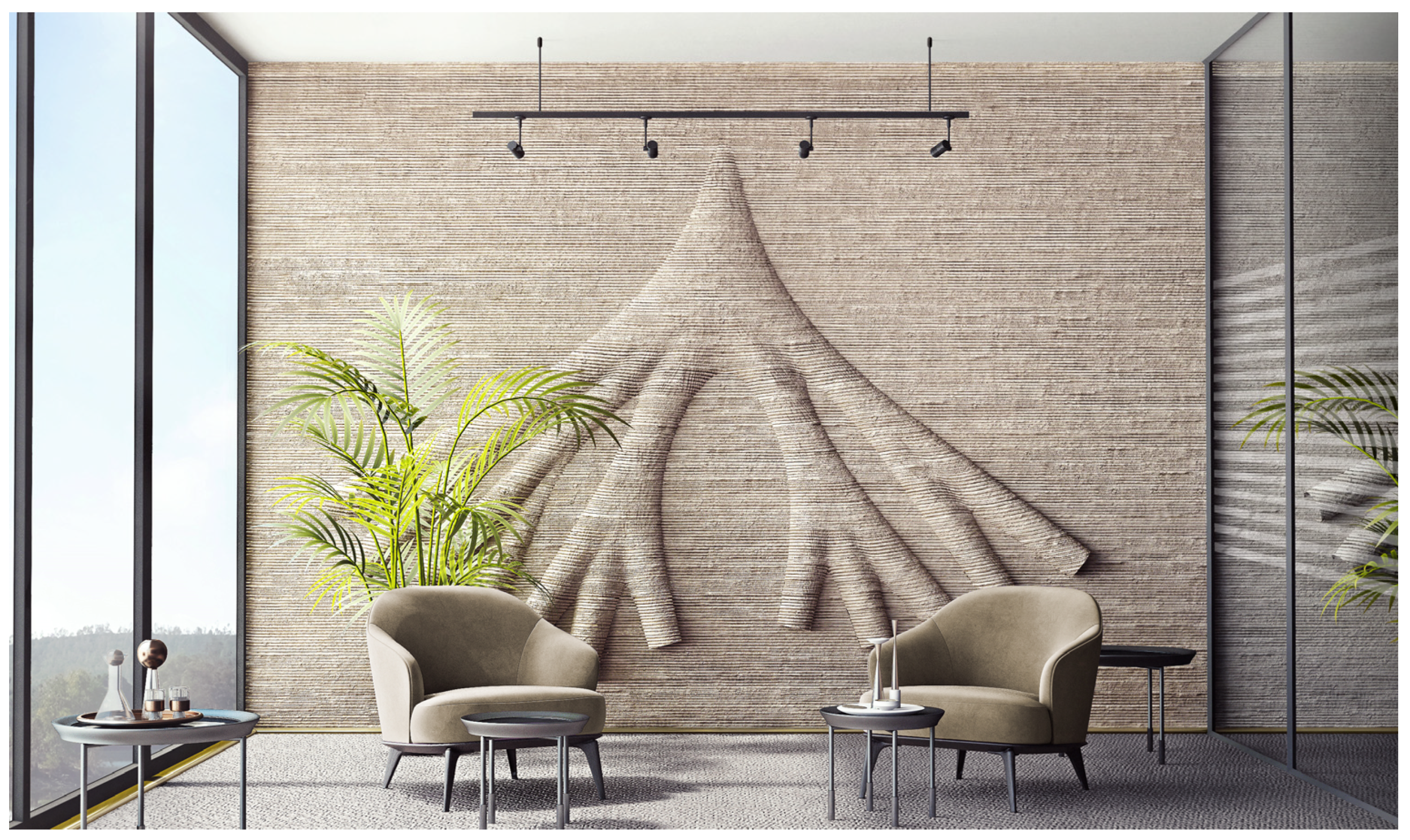
This research presents an integrated design and manufacturing workflow that demonstrates how AM can be used for producing building components with integrated displacement ventilation distribution. The integration of an air distribution duct network into a building component, such as a façade wall, results in intricate geometric designs, which validate the use of AM technology for production. In this context, AM is suggested as an enabling technology, the absence of which makes the production of such complex forms inefficient, if not impossible. It is also suggested that such integration through AM can make the construction process more efficient by eliminating the need to install additional ventilation equipment after the wall is built. Moreover, the research argues that low-carbon building materials such as clay can be used for the production of these complex components towards more environmentally friendly solutions. Last but not least, with this approach, typical ventilation ducts can be revisited as aesthetical spatial components with exceptional architectural qualities as seen in Figure 23.
The experiments on a proof of concept demonstrate that available software and methods in computational design and analysis can provide solutions for a workflow that integrates concept-design development, analysis, optimization, and fabrication through AM. In this project, the ventilation distribution was designed following the conventional design principles that are used in common duct installations. Based on this, evaluation criteria were set for the verification of a more complex design. Different variants of a complex-shaped ventilation system were generated and verified via CFD simulations. A portion of the final design was prototyped in a 1:1 scale to test the efficiency of clay for manufacturing the resulting complex geometry through AM by using a robot arm. The geometry was further analyzed and optimized to improve the structural and thermal performance of the object through a customizable infill pattern design.
The object geometry, including the custom infill pattern and the robot toolpath needed to manufacture the prototype, were designed through a parametric model in Grasshopper 1.0 software. Then, RoboDK 3.8 software was used to simulate the robot and to generate the offline robot program.
The prototype was manufactured using clay. Based on the literature review and material experiments, the mixture of clay, gypsum, and chamotte was considered the best in its performance and hence was used further in this research for prototyping. The most appropriate material composition for manufacturing the designed prototype with the available infrastructure and hardware was found to be 30% chamotte, 10% gypsum, and 30% water, in proportion to the clay used. Stoneware clay was chosen due to its suitable architectural properties in terms of surface stiffness, shrinkage rate, and availability. In terms of the material qualities, the main conclusions of this research include that it is important to achieve good viscosity and to maintain it through the manufacturing process. Air cavities and clay lumps in the paste should be avoided when filling in the cartridge. It is advised that after preparing the paste, it should be kept covered to keep its moisture while waiting for manufacturing. In this research, the preparation of the material, from mixing the composite to filling the cartridge, required prominently manual labor. Automation of this process could be investigated in future research.
The size of the cartridge directly influences the maximum size of the object that will be manufactured. The volume of the cartridge used in this research was limited to 2.5 L. A larger cartridge would enable the production of larger objects. Moreover, a cartridge system with integrated continuous material feed could theoretically eliminate this limitation and it could help to obtain a more homogenous material flow along the entire manufacturing process.
The extruder used in this research was controlled via Wi-Fi to start and stop the extrusion, and to change the extrusion speed. This required visually following the extrusion and manually adjusting it when needed. Integrating the material flow rate as a variable in the robot program and adjusting it in an automated way concerning the toolpath could improve the level of automation in manufacturing. However, we suggest that manual control of material flow would still be useful to overwrite when needed.
Eventually, clay was found to be potentially usable in large-scale components through AM. However, more research is needed to address problems such as shrinkage, cracks, and changes in dimensions after the object dries. In this research, the prototype was not fired. The effects of firing the manufactured object need to be investigated in further research as well. Improvements in the extrusion setup, particularly customizing material flow rate along the toolpath, need to be explored. As a common outcome of large-scale AM, the surfaces of the final prototype have a certain degree of roughness, which was not included in the CFD simulations. The effects of surface roughness on airflow can be analyzed in further research through simulations and tests on physical prototypes.
Supplementary Materials
The following supporting information can be downloaded at: https://www.mdpi.com/article/10.3390/buildings13112676/s1, Figure S1: Images of extrusion experiments with different material mixtures; Table S1: Material Experiment Results.
Author Contributions
This article was produced as an output from the MSc graduation thesis [37] of A.T. The first mentor of the aforementioned graduation thesis is S.A., who has supervised the project within the computational design and additive manufacturing aspects. The second mentor of the graduation thesis is W.v.d.S., who has supervised the project within climate design and computational fluid dynamics aspects. The contributor roles are as follows; Investigation and writing the original draft: A.T.; Supervision and article review and editing: S.A. and W.v.d.S. All authors have read and agreed to the published version of the manuscript.
Funding
This research received no external funding.
Data Availability Statement
Not applicable.
Acknowledgments
The authors acknowledge the contributions of Michela Turrin for guidance during material experiments, and Paul de Ruiter for support with AM hardware during prototyping.
Conflicts of Interest
The authors declare no conflict of interest.
References
- Mihai, V.; Liliana, R. Cfd Analysis and Wind Tunnel Experiment for Ventilation Ducts with Structural Elements Inside. J. Mar. Sci. Eng. 2023, 11, 371. [Google Scholar] [CrossRef]
- Wang, H.; Li, X.; Tang, Y.; Chen, X.; Shen, H.; Cao, X.; Gao, H. Simulation and Experimental Study on the Elbow Pressure Loss of Large Air Duct with Different Internal Guide Vanes. Build. Serv. Eng. Res. Technol. 2022, 43, 725–739. [Google Scholar] [CrossRef]
- de Witte, D.; de Klijn-Chevalerias, M.L.; Loonen, R.C.; Hensen, J.L.; Knaack, U.; Zimmermann, G. Convective Concrete: Additive Manufacturing to Facilitate Activation of Thermal Mass. J. Facade Des. Eng. 2017, 5, 107–117. [Google Scholar]
- Gocmen, K.; Soyhan, H.S. An Intake Manifold Geometry for Enhancement of Pressure Drop in a Diesel Engine. Fuel 2020, 261, 116193. [Google Scholar] [CrossRef]
- Xu, J. Flow Analysis of Engine Intake Manifold Based on Computational Fluid Dynamics. J. Phys. Conf. Ser. 2017, 916, 012043. [Google Scholar] [CrossRef]
- Zardin, B.; Giovanni, C.; Carlo, R.; Enrico, M.; Massimo, B. Pressure Losses in Hydraulic Manifolds. Energies 2017, 10, 310. [Google Scholar] [CrossRef]
- Dhokia, V.; Wesley, P.E.; Joseph, M.F. A Generative Multi-Agent Design Methodology for Additively Manufactured Parts Inspired by Termite Nest Building. CIRP Annals 2017, 66, 153–156. [Google Scholar] [CrossRef]
- ISO/ASTM 52900:2021; Additive Manufacturing-General Principles-Fundamentals and Vocabulary. ASTM International: West Conshohocken, PA, USA, 2021.
- Ngo, T.D.; Alireza, K.; Gabriele, I.; Kate TQ, N.; David, H. Additive Manufacturing (3D Printing): A Review of Materials, Methods, Applications and Challenges. Compos. Part B Eng. 2018, 143, 172–196. [Google Scholar] [CrossRef]
- Altıparmak, S.C.; Yardley, V.A.; Shi, Z.; Lin, J. Extrusion-Based Additive Manufacturing Technologies: State of the Art and Future Perspectives. J. Manuf. Process. 2022, 83, 607–636. [Google Scholar] [CrossRef]
- Romani, A.; Rognoli, V.; Levi, M. Design, Materials, and Extrusion-Based Additive Manufacturing in Circular Economy Contexts: From Waste to New Products. Sustainability 2021, 13, 7269. [Google Scholar] [CrossRef]
- Valente, M.; Abbas, S.; Matteo, S. Extrusion-Based Additive Manufacturing of Concrete Products: Revolutionizing and Remodeling the Construction Industry. J. Compos. Sci. 2019, 3, 88. [Google Scholar] [CrossRef]
- Placzek, G.; Schwerdtner, P. Concrete Additive Manufacturing in Construction: Integration Based on Component-Related Fabrication Strategies. Buildings 2023, 13, 1769. [Google Scholar] [CrossRef]
- Paolini, A.; Stefan, K.; Ernst, R. Additive Manufacturing in Construction: A Review on Processes, Applications, and Digital Planning Methods. Addit. Manuf. 2019, 30, 100894. [Google Scholar] [CrossRef]
- Baigarina, A.; Shehab, E.; Ali, H. Construction 3D Printing: A Critical Review and Future Research Directions. Prog. Addit. Manuf. 2023. [Google Scholar] [CrossRef]
- Puzatova, A.; Pshtiwan, S.; Vittoria, L.; Maria, D. Large-Scale 3D Printing for Construction Application by Means of Robotic Arm and Gantry 3D Printer: A Review. Buildings 2022, 12, 2023. [Google Scholar] [CrossRef]
- Bici, A.; Yunitsyna, A. Analysis of 3D Printing Techniques for Building Construction: A Review. Constr. Robot. 2023, 7, 107–123. [Google Scholar] [CrossRef]
- Camacho, D.D.; Clayton, P.; O’Brien, W.J.; Seepersad, C.; Juenger, M.; Ferron, R.; Salamone, S. Applications of Additive Manufacturing in the Construction Industry—A Forward-Looking Review. Autom. Constr. 2018, 89, 110–119. [Google Scholar] [CrossRef]
- Ghaffar, S.H.; Corker, J.; Fan, M. Additive Manufacturing Technology and Its Implementation in Construction as an Eco-Innovative Solution. Autom. Constr. 2018, 93, 1–11. [Google Scholar] [CrossRef]
- Gomaa, M.; Jabi, W.; Soebarto, V.; Xie, Y.M. Digital Manufacturing for Earth Construction: A Critical Review. J. Clean. Prod. 2022, 338, 130630. [Google Scholar] [CrossRef]
- Aayushi, B.; Farahbakhsh, M.; Zakira, U.; Pandey, A.; Ennab, L.A.; Rybkowski, Z.; Dixit, M.K.; Schwab, P.A.; Kalantar, N.; Birgisson, B.; et al. In Situ Resource Utilization and Reconfiguration of Soils into Construction Materials for the Additive Manufacturing of Buildings. Front. Mater. 2020, 7, 52. [Google Scholar]
- Matthias, L.; Cheibas, I.; Piccioni, V.; Seshadri, B.; Schlüter, A.; Gramazio, F.; Kohler, M.; Dillenburger, B. 3D Printing Facades: Design, Fabrication, and Assessment Methods. Autom. Constr. 2023, 152, 104918. [Google Scholar]
- Alexandre, D.; Cabay, E.; Chronis, A. Energy Efficient Design for 3D Printed Earth Architecture. In Humanizing Digital Reality; Springer: Singapore, 2018; pp. 383–393. [Google Scholar]
- Moretti, M. Wasp in the Edge of 3D Printing. In 3D Printing for Construction with Alternative Materials; Springer International Publishing: Cham, Switzerland, 2023; pp. 57–65. [Google Scholar]
- Sangiorgio, V.; Parisi, F.; Fieni, F.; Parisi, N. The New Boundaries of 3D-Printed Clay Bricks Design: Printability of Complex Internal Geometries. Sustainability 2022, 14, 598. [Google Scholar] [CrossRef]
- Abdallah, Y.K.; Estévez, A.T. 3D-Printed Biodigital Clay Bricks. Biomimetics 2021, 6, 59. [Google Scholar] [CrossRef] [PubMed]
- Kontovourkis, O.; Tryfonos, G. Robotic 3D Clay Printing of Prefabricated Non-Conventional Wall Components Based on a Parametric-Integrated Design. Autom. Constr. 2020, 110, 103005. [Google Scholar] [CrossRef]
- Fratello, V.S.; Ronald, R. Innovating Materials for Large Scale Additive Manufacturing: Salt, Soil, Cement and Chardonnay. Cem. Concr. Res. 2020, 134, 106097. [Google Scholar] [CrossRef]
- Cruz, P.J.; Camões, A.; Figueiredo, B.; Ribeiro, M.J.; Renault, J. Additive Manufacturing Effect on the Mechanical Behaviour of Architectural Stoneware Bricks. Constr. Build. Mater. 2020, 238, 117690. [Google Scholar] [CrossRef]
- Kosonen, R.; Melikov, A.K.; Mundt, E.; Mustakalio, P.; Nielsen, P.V. Displacement Ventilation. In Rehva Guidebooks: Federation of European Heating and Air-Conditioning Associations; REHVA: Ixelles, Belgium, 2017. [Google Scholar]
- Displacement Ventilation Engineering Guide. In Price Engineer’s Hvac Handbook; Price Industries Limited: Winnipeg, MB, Canada, 2016.
- Beck, H.E.; Zimmermann, N.E.; McVicar, T.R.; Vergopolan, N.; Berg, A.; Wood, E.F. Present and Future Köppen-Geiger Climate Classification Maps at 1-Km Resolution. Sci. Data 2018, 5, 180214. [Google Scholar] [CrossRef]
- Ashrae Handbook—Fundamentals, SI ed; ASHRAE Research: Peachtree Corners, GA, USA, 2021.
- López-Ochoa, L.M.; Bobadilla-Martínez, D.; Las-Heras-Casas, J.; López-González, L.M. Towards Nearly Zero-Energy Educational Buildings with the Implementation of the Energy Performance of Buildings Directive Via Energy Rehabilitation in Cold Mediterranean Zones: The Case of Spain. Energy Rep. 2019, 5, 1488–1508. [Google Scholar] [CrossRef]
- Rhodes, D. Clay and Glazes for the Potter; Greenberg Publisher: New York, NY, USA, 1957. [Google Scholar]
- Etuk, S.E.; Akpabio, I.O.; Udoh, E.M. Comparison of the Thermal Properties of Clay Samples as Potential Walling Material for Naturally Cooled Building Design. J. Environ. Sci. 2003, 15, 65–68. [Google Scholar]
- Taher, A. 3D Printing Clay Facade Walls: Integrating Ventilation Systems into Printing Process. Master’s Thesis, Delft University of Technology, Delft, The Netherlands, 2019. [Google Scholar]
Figure 1.
Left: Mixing Ventilation System. Right: Displacement Ventilation System (Source: [31]). Blue arrows show the movement of the supplied fresh air inside the room. Yellow arrows show the movement of the contaminated air inside the room. Yellow dots indicate the air contamination in the room.
Figure 1.
Left: Mixing Ventilation System. Right: Displacement Ventilation System (Source: [31]). Blue arrows show the movement of the supplied fresh air inside the room. Yellow arrows show the movement of the contaminated air inside the room. Yellow dots indicate the air contamination in the room.

Figure 2.
The layout of the office space ((A) Top view. (B) Axonometric view). The façade wall that is designed in this project as the case study is indicated in orange. The blue walls are the other walls of the office room.
Figure 2.
The layout of the office space ((A) Top view. (B) Axonometric view). The façade wall that is designed in this project as the case study is indicated in orange. The blue walls are the other walls of the office room.

Figure 3.
(A) Air supply in the horizontal direction through adjacent units (orange arrows indicate the airflow direction). (B) The air supply in the vertical direction from the main supply to a specific unit (blue arrows indicate the airflow direction).
Figure 3.
(A) Air supply in the horizontal direction through adjacent units (orange arrows indicate the airflow direction). (B) The air supply in the vertical direction from the main supply to a specific unit (blue arrows indicate the airflow direction).

Figure 4.
The effects of the printing direction ((A): horizontal, (B): vertical) on product stability and printing overhangs (Blue lines indicate the direction of the printing layers. Orange lines indicate the rotation.).
Figure 4.
The effects of the printing direction ((A): horizontal, (B): vertical) on product stability and printing overhangs (Blue lines indicate the direction of the printing layers. Orange lines indicate the rotation.).
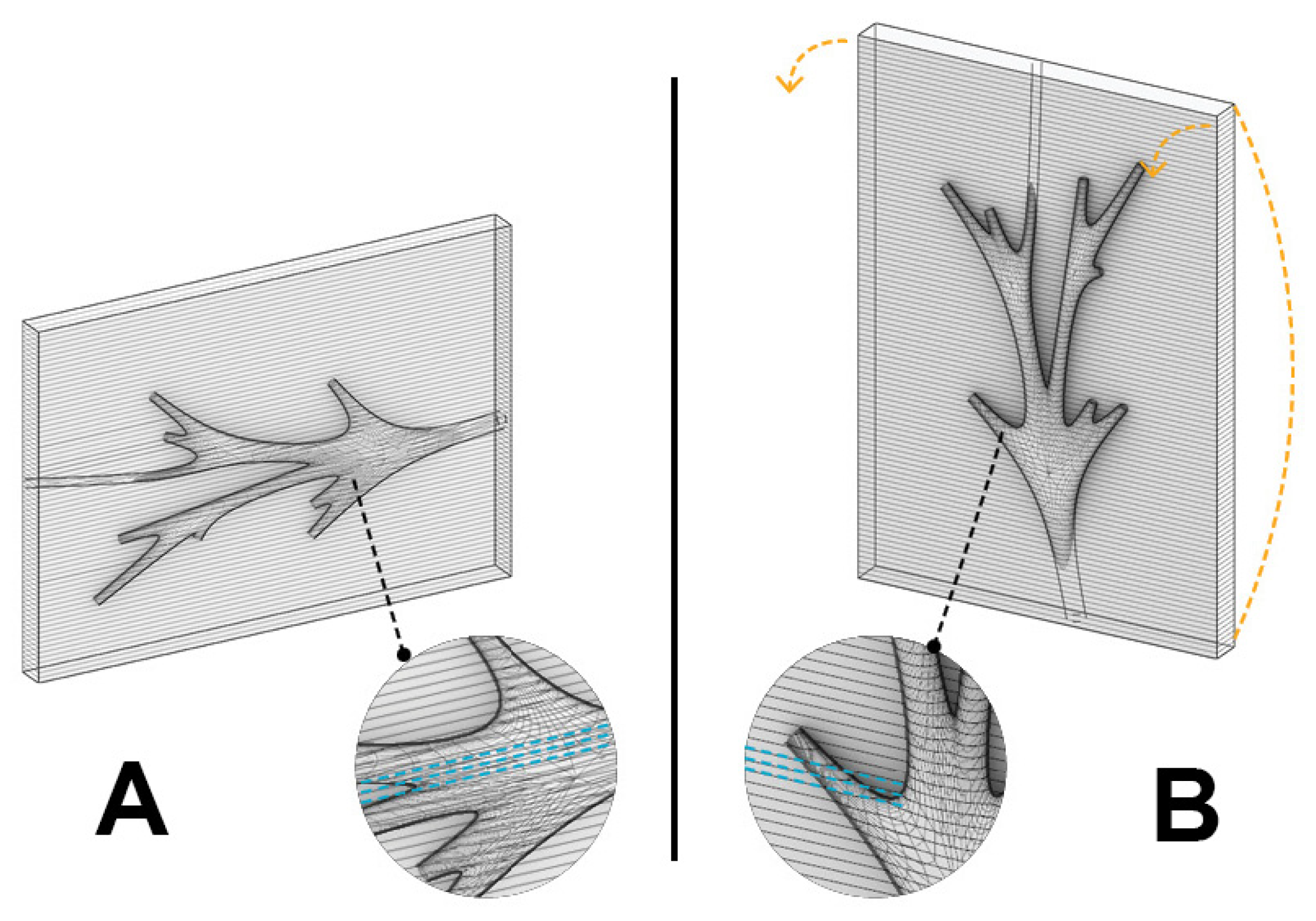
Figure 5.
The four design principles for the morphology of the duct. (A) Shortest network, (B) Inlet–outlet ratio, (C) Smooth corners, (D) Overhang outlets.
Figure 5.
The four design principles for the morphology of the duct. (A) Shortest network, (B) Inlet–outlet ratio, (C) Smooth corners, (D) Overhang outlets.
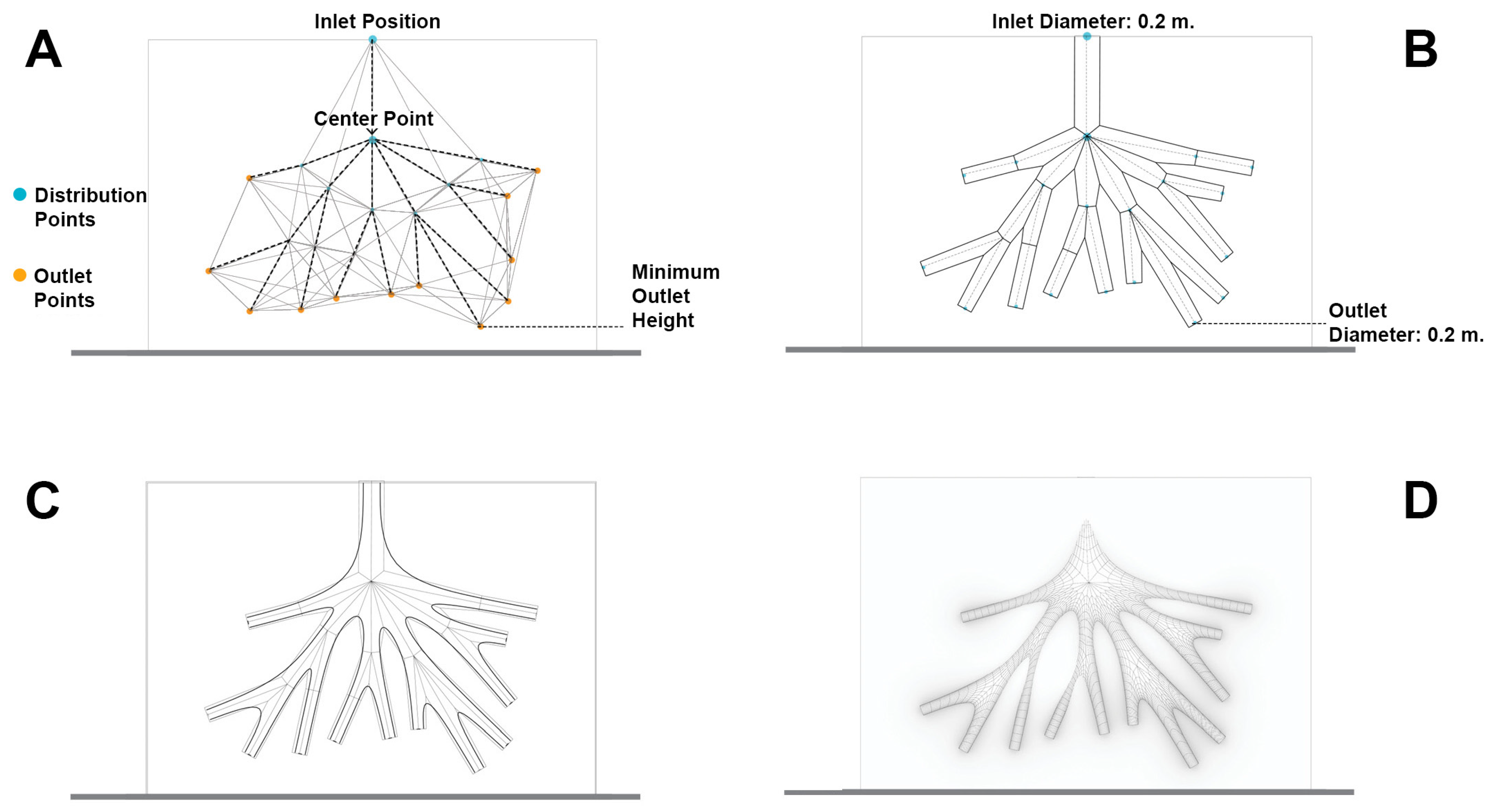
Figure 6.
Refinement and design principles for the façade morphology as concluded from analysis simulations. (A) Branching angle limits, (B) Direct inlet to outlet flow, (C) Cavities.
Figure 6.
Refinement and design principles for the façade morphology as concluded from analysis simulations. (A) Branching angle limits, (B) Direct inlet to outlet flow, (C) Cavities.
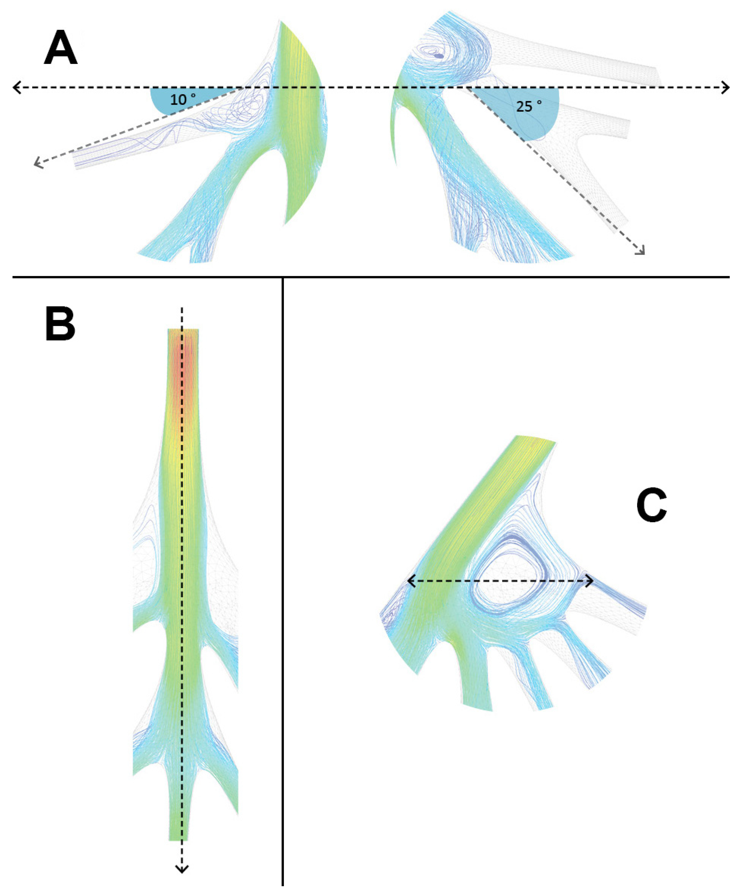
Figure 7.
The four different geometries (G1, G2, G3, G4) that were designed and analyzed through CFD.
Figure 7.
The four different geometries (G1, G2, G3, G4) that were designed and analyzed through CFD.

Figure 8.
The design of the integrated ventilation-distribution network in the wall. The indicated part was selected for prototyping through AM.
Figure 8.
The design of the integrated ventilation-distribution network in the wall. The indicated part was selected for prototyping through AM.

Figure 9.
The outlets, overhangs, and inner ducts, seen within the part chosen for prototyping. (A) The original orientation of the part. (B) The part rotated 180° for prototyping (the blue arrows indicate the rotation).
Figure 9.
The outlets, overhangs, and inner ducts, seen within the part chosen for prototyping. (A) The original orientation of the part. (B) The part rotated 180° for prototyping (the blue arrows indicate the rotation).
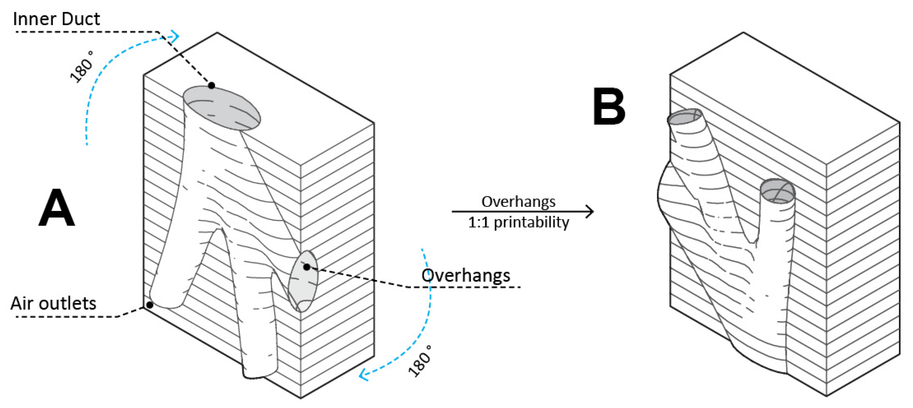
Figure 10.
The three main forces (self-weight of the shell, self-weight of the inner air ducts, and lateral outdoor forces) that were considered in the infilling design.
Figure 10.
The three main forces (self-weight of the shell, self-weight of the inner air ducts, and lateral outdoor forces) that were considered in the infilling design.

Figure 11.
The infilling pattern design options. (A) The boundary without infilling, (B) the linear infilling design using projected points, (C) the linear infilling design using the duct normals, (D) the cubic infilling design using intersecting straight lines as a weaving pattern.
Figure 11.
The infilling pattern design options. (A) The boundary without infilling, (B) the linear infilling design using projected points, (C) the linear infilling design using the duct normals, (D) the cubic infilling design using intersecting straight lines as a weaving pattern.

Figure 12.
Thermal performance of (A) solid and void volumes within the wall, (B) infilling, and (C) cavities.
Figure 12.
Thermal performance of (A) solid and void volumes within the wall, (B) infilling, and (C) cavities.
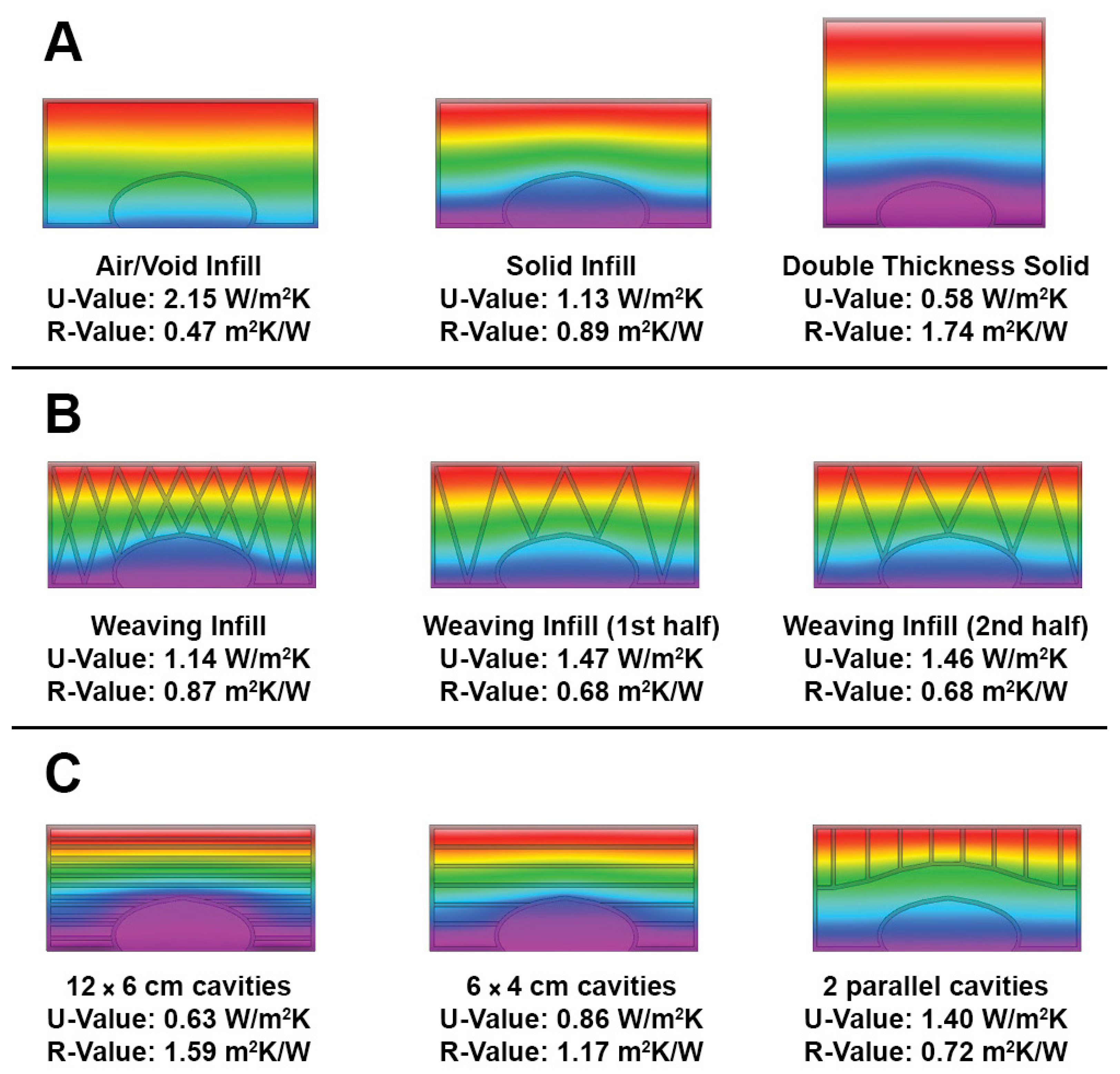
Figure 13.
(A) The final infilling design. (B) Thermal results for a U-value of 0.73 W/m2K. (C) The prototype design, shows the weaving pattern infilling and the horizontal thermal barriers.
Figure 13.
(A) The final infilling design. (B) Thermal results for a U-value of 0.73 W/m2K. (C) The prototype design, shows the weaving pattern infilling and the horizontal thermal barriers.

Figure 14.
Three infilling density options ((A) High-density infilling, (B) Mid-density infilling, (C) Low-density infilling).
Figure 14.
Three infilling density options ((A) High-density infilling, (B) Mid-density infilling, (C) Low-density infilling).

Figure 15.
Samples from the preliminary extrusion tests, showing the selected material mixture (with chamotte 0–0.2 mm and gypsum). ((A) Top view, (B) Side view).
Figure 15.
Samples from the preliminary extrusion tests, showing the selected material mixture (with chamotte 0–0.2 mm and gypsum). ((A) Top view, (B) Side view).

Figure 16.
(A) The stepper motor is attached to the screw used for extrusion. (B) The metal case. (C) The nozzle. (D) The complete extrusion system is mounted on the robot arm.
Figure 16.
(A) The stepper motor is attached to the screw used for extrusion. (B) The metal case. (C) The nozzle. (D) The complete extrusion system is mounted on the robot arm.

Figure 17.
Illustration of the integrated digital workflow, including the main phases and the software used.
Figure 17.
Illustration of the integrated digital workflow, including the main phases and the software used.

Figure 18.
Discontinuity in extrusion, caused by the clogged nozzle ((A) Top view, (B) Side view). (The marks in cyan color indicate the spots where discontinuity is visible).
Figure 18.
Discontinuity in extrusion, caused by the clogged nozzle ((A) Top view, (B) Side view). (The marks in cyan color indicate the spots where discontinuity is visible).
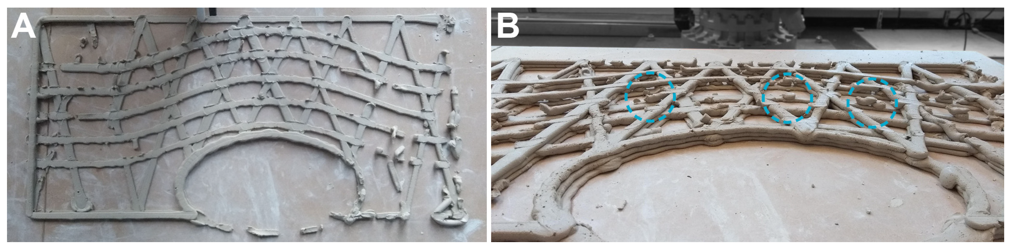
Figure 19.
Damages and discontinuities caused by Air Shots. (A) A damage affected multiple layers (marked in cyan). (B) Discontinuity within layers (marked in cyan).
Figure 19.
Damages and discontinuities caused by Air Shots. (A) A damage affected multiple layers (marked in cyan). (B) Discontinuity within layers (marked in cyan).

Figure 20.
The cracks that are caused by shrinkage. (A) Cracks near the intersection nodes. (C) Cracks near the intersection nodes, on adjacent layers. (B,D) Highlighting the cracks (cyan) and intersection nodes (yellow) in the top view.
Figure 20.
The cracks that are caused by shrinkage. (A) Cracks near the intersection nodes. (C) Cracks near the intersection nodes, on adjacent layers. (B,D) Highlighting the cracks (cyan) and intersection nodes (yellow) in the top view.
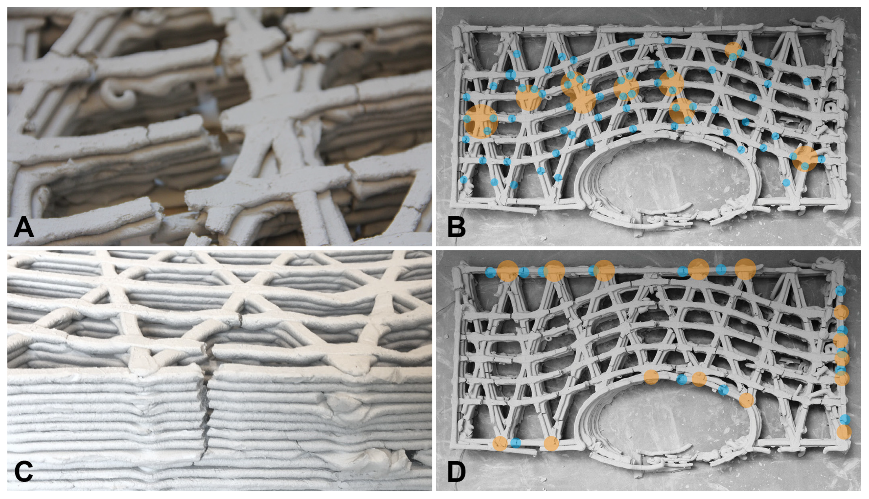
Figure 21.
The effects of the manufacturing bed ((A) Prototype on the bed with a plastic cover. (B) Prototype on the MDF board.).
Figure 21.
The effects of the manufacturing bed ((A) Prototype on the bed with a plastic cover. (B) Prototype on the MDF board.).
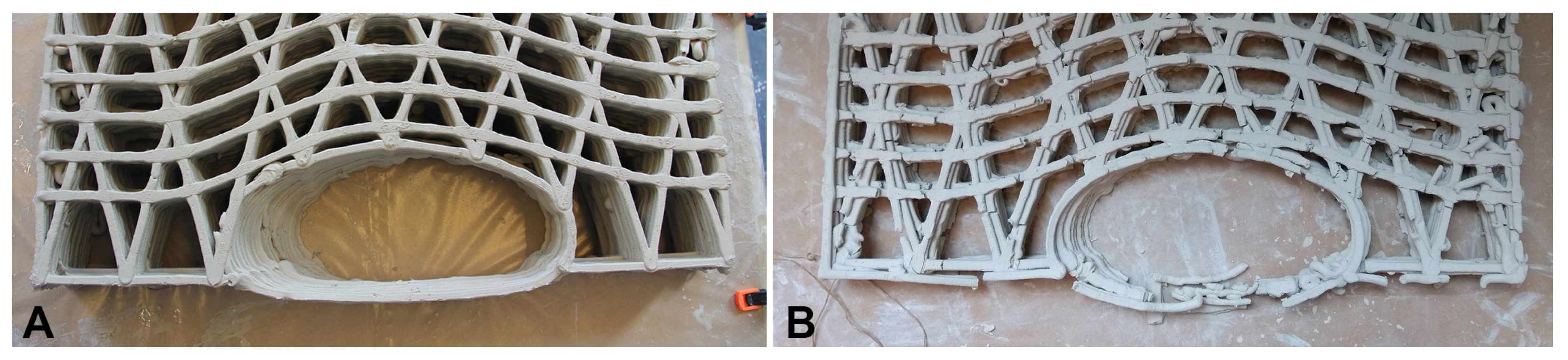
Figure 22.
The final prototype.
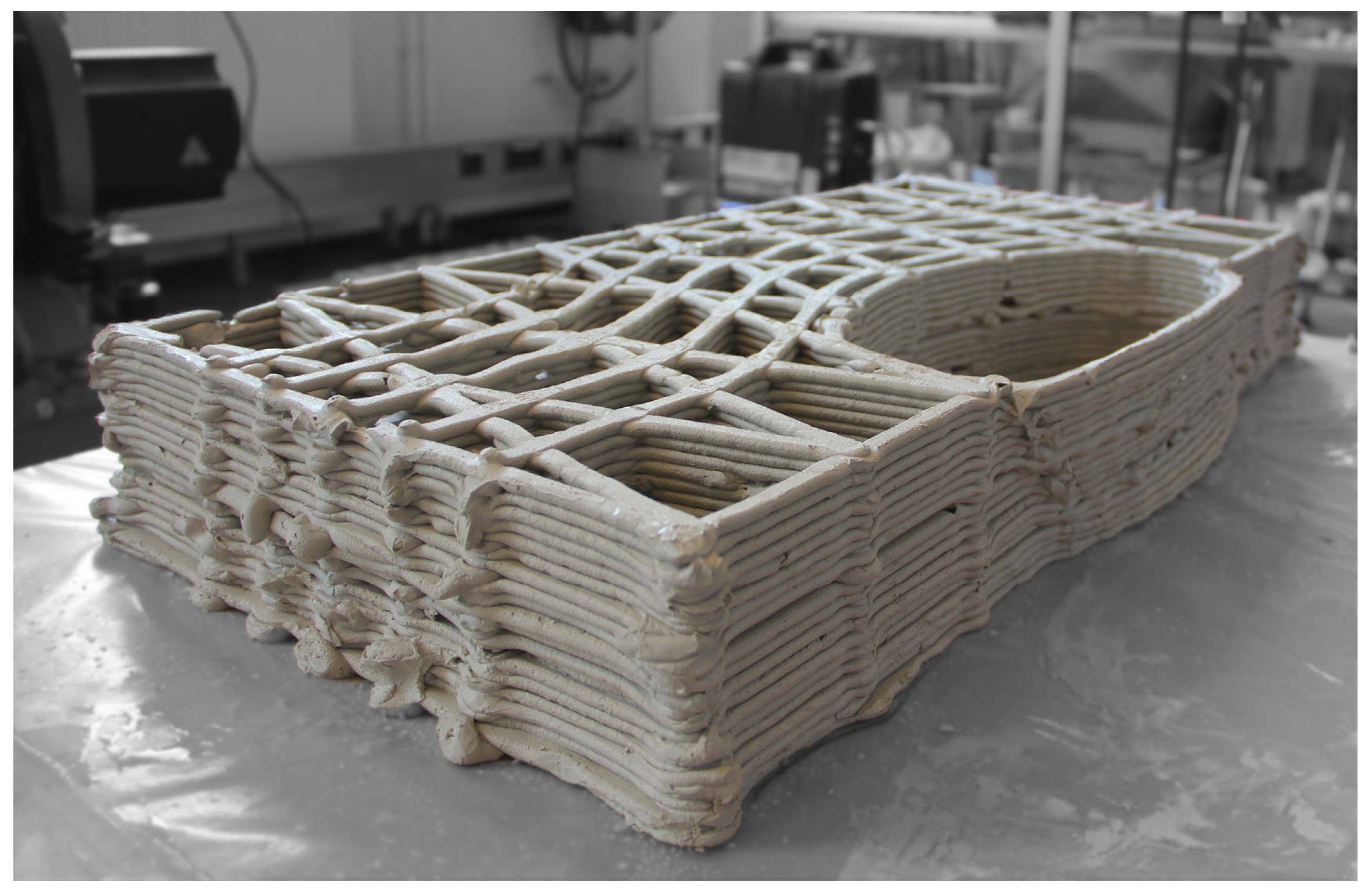
Figure 23.
An illustration of the concept design of the wall with integrated ventilation.

Table 1.
Summary of the calculated values used to determine the initial design and verification criteria for the façade morphology.
Table 1.
Summary of the calculated values used to determine the initial design and verification criteria for the façade morphology.
| Method | Function | Value |
|---|---|---|
| Design Builder Analysis | U-Value | 0.73 W/m2K |
| Cooling load | 1.0 kW | |
| Literature Review | Supply air temperature | 18 °C |
| Cooling setpoint | 26 °C | |
| Reynolds number | 39,452 | |
| Case Study Design | Airflow rate | 100 dm3/s |
| Friction Loss Diagram [33] | Pressure loss | 0.6 Pa/m |
| Duct diameter | 0.2 m |
Table 2.
Summary of the main characteristics obtained from the CFD analysis of four different geometries (based on a flow path of 3 m in length).
Table 2.
Summary of the main characteristics obtained from the CFD analysis of four different geometries (based on a flow path of 3 m in length).
| Geometry | G1 | G2 | G3 | G4 |
|---|---|---|---|---|
| Mesh faces | 311,986 | 248,570 | 269,197 | 328,324 |
| Area in/out ratio | 4.4 | 4 | 4 | 4.4 |
| Average outlet velocity (m/s) | 0.72 | 0.76 | 0.76 | 0.69 |
| Total pressure (Pa) | 2.73 | 2.26 | 2.67 | 2.58 |
| Pressure drop (Pa/m) | 0.91 | 0.75 | 0.89 | 0.85 |
Table 3.
Comparison of clay types. Stoneware is the type of clay which is used in this research.
| Clay Type | Color | Temperature | Plasticity | Availability | Shrinkage | Surface Stiffness | Thermal Resistivity |
|---|---|---|---|---|---|---|---|
| Kaolin | Whites | <1800 °C | Low | Low | Low | Low | 2.70 W−1mK |
| Stoneware | Grays | 1200 °C–1300 °C | Mid–High | High | Acceptable | High | 2.58 W−1mK |
| Earthenware | Red, Brown, Black | 950 °C–1000 °C | Low–High | High | N/A | Medium | 2.16 W−1mK |
Disclaimer/Publisher’s Note: The statements, opinions and data contained in all publications are solely those of the individual author(s) and contributor(s) and not of MDPI and/or the editor(s). MDPI and/or the editor(s) disclaim responsibility for any injury to people or property resulting from any ideas, methods, instructions or products referred to in the content. |
© 2023 by the authors. Licensee MDPI, Basel, Switzerland. This article is an open access article distributed under the terms and conditions of the Creative Commons Attribution (CC BY) license (https://creativecommons.org/licenses/by/4.0/).
Share and Cite
MDPI and ACS Style
Taher, A.; Aşut, S.; van der Spoel, W. An Integrated Workflow for Designing and Fabricating Multi-Functional Building Components through Additive Manufacturing with Clay. Buildings 2023, 13, 2676. https://doi.org/10.3390/buildings13112676
AMA Style
Taher A, Aşut S, van der Spoel W. An Integrated Workflow for Designing and Fabricating Multi-Functional Building Components through Additive Manufacturing with Clay. Buildings. 2023; 13(11):2676. https://doi.org/10.3390/buildings13112676
Chicago/Turabian StyleTaher, Ammar, Serdar Aşut, and Willem van der Spoel. 2023. "An Integrated Workflow for Designing and Fabricating Multi-Functional Building Components through Additive Manufacturing with Clay" Buildings 13, no. 11: 2676. https://doi.org/10.3390/buildings13112676
Note that from the first issue of 2016, this journal uses article numbers instead of page numbers. See further details here.