Article

Fatigue Behavior of M20 Torque Shear High-Strength Bolts under Constant-Amplitude Loading

College of Civil Engineering, Taiyuan University of Technology, Taiyuan 030024, China
*
Author to whom correspondence should be addressed.
Buildings 2023, 13(2), 367; https://doi.org/10.3390/buildings13020367
Submission received: 26 November 2022 / Revised: 5 January 2023 / Accepted: 23 January 2023 / Published: 28 January 2023

Abstract

:
Torque-shear high strength bolts were developed and widely used recently, and such high-tensile bolts may fracture in practical engineering due to the frequent complex loads, resulting in economic losses and even casualties. However, the fatigue performance of M20 torque shear high-strength bolts under constant-amplitude loading has not been investigated yet, and there are no specific design provisions for determining the constant-amplitude fatigue performance of such bolts. Hence, a total of 10 constant-amplitude fatigue tests were conducted using an MTS fatigue testing machine. For comparison, five different stress amplitudes were investigated. The fatigue performance, stress concentration and fracture analysis were analyzed. The scanning electron microscope images of fatigue failure were obtained to analyze the fatigue fracture characteristics of high-tensile bolts. A finite element model was established to analyze the stress distribution and the hot-spot stress of the bolts. The results suggested that the allowable nominal stress amplitude of M20 torque-shear type high-strength bolts was 96.371 MPa, while the allowable hot-spot stress amplitude was 283.296 MPa. Finally, the test results were compared against the existing design provisions. Upon comparison, the existing design formulas in GB 50017(2017), ANSI/AISC 360-16 (2010) and Eurocode 3 (2003) were found to be generally conservative. The S-N curve of torque-shear high strength bolts under constant-amplitude loading was proposed using the hot-spot stress amplitudes.

1. Introduction

The use of high-strength bolt connections is widely popular in offshore and fabricated structures, and the forces and moments generated by the effects of winds, waves and complex loads may contribute to fracture in practical engineering, resulting in economic losses and even casualties. Fatigue failure is found to be the primary reason for structural collapse. The M20 torque-shear high strength bolts (HSBs) were developed and widely used as shown in Figure 1, which was crucial for connecting the structures in fabricated construction.
In the literature, a significant number of studies have been performed investigating the fatigue performance of high-tensile bolts [1,2]. Qiu et al. [3] conducted constant-amplitude fatigue tests to investigate the behavior of M30 high-strength bolts, and they developed stress-fatigue life curves using the stress range. A high-cycle fatigue damage model was used to evaluate the development process of fatigue damage in this study. Yang et al. [4,5] experimentally investigated the fatigue failure of high-strength bolts under constant-amplitude loading, and fractographic analysis was conducted to investigate the fatigue fracture characteristics of such bolts. They found that the effect of the stress amplitude on the fatigue strength of M20 torque-shear high strength bolts was significant. Jiao et al. [6] performed a total of 21 fatigue tests to investigate the constant-amplitude fatigue performance of grade 8.8 M24 high-strength bolts, and the test results suggested that the fatigue strength of the high-strength bolt was 1.60 to 1.87 times greater than the values obtained from the existing design standards. Zhao [7] suggested that the influence of lead angle on the contact load distribution could be ignored, when the angle of the bolt thread was less than 4°. Considering the action of axial loading, it is assumed that the bolts could be axisymmetric for simplicity. Lochan et al. [8] summarized a detailed review of the main challenges for fatigue life assessment of M72 bolted connections used in offshore structures, and they indicated that the key challenges in fatigue life assessment of large-scale bolts is the lack of test data, from which fatigue design curves can be derived. Design recommendations have been established for enhancing the existing fatigue assessment. Zhou et al. [9] established the constant-amplitude fatigue design method as well as stress-fatigue life curve using regression analysis, which can provide an essential scientific basis for the application of high-strength bolts with a large-size diameter. A total of 133 fatigue tests were conducted by Nam et al. [10] recently, and they proposed a novel approach and a unified stress-fatigue life curve for three different bolts under different axial loading conditions using experimental and numerical investigation. The effects of hot-spot stress on the fatigue behavior of bolt connections have been investigated by many researchers [11,12,13].
Limited work has been reported on the behavior of torque shear high-strength bolts. Only Nah and Choi [14] conducted tensile tests to investigate the effects of different key factors on the behavior of torque shear type high-strength bolt, and they proposed a method to determine the clamping force of such bolts. However, no work in the literature has been reported for investigating the fatigue behavior of M20 torque shear high-strength bolts under constant-amplitude loading. Furthermore, current design guidance in GB 50017 [15], ANSI/AISC 360-16 [16] and Eurocode 3 [17] does not include direct guidance for determining the fatigue behavior of such bolts. The limitations of existing design code procedures can affect the design flexibility and decrease the reliability of torque shear high-strength bolts in the modern construction industry.
This paper reports the details of 10 new experiments on the fatigue performance of M20 torque-shear high strength bolts under constant-amplitude loading. The fatigue performance, stress concentration and fracture analysis are analyzed in this study. A finite element model was established to investigate the stress distribution and the hot-spot stress of the bolts. The S-N curve was fitted using the nominal stress amplitude. The S-N fatigue curve of torque-shear high strength bolts under constant-amplitude loading was proposed using the hot-spot stress amplitudes as a design parameter. Finally, the test results were compared against the existing design provisions in GB 50017 [15], ANSI/AISC 360-16 [16] and Eurocode 3 [17].

2. Experimental Study

2.1. Specimen Design

2.1.1. M20 Torque Shear High-Strength Bolts

M20 torque shear high-strength bolts were used in this study, as shown in Figure 1. Such bolts were made of ML20MnTiB having a 10.9 S performance rating, and the detailed dimensions of bolts are presented in Figure 1a. It should be noted that the bolts’ appearances were visually examined to exclude cracked, corroded, or damaged bolts prior to the fatigue tests.

2.1.2. T-Shaped Connector

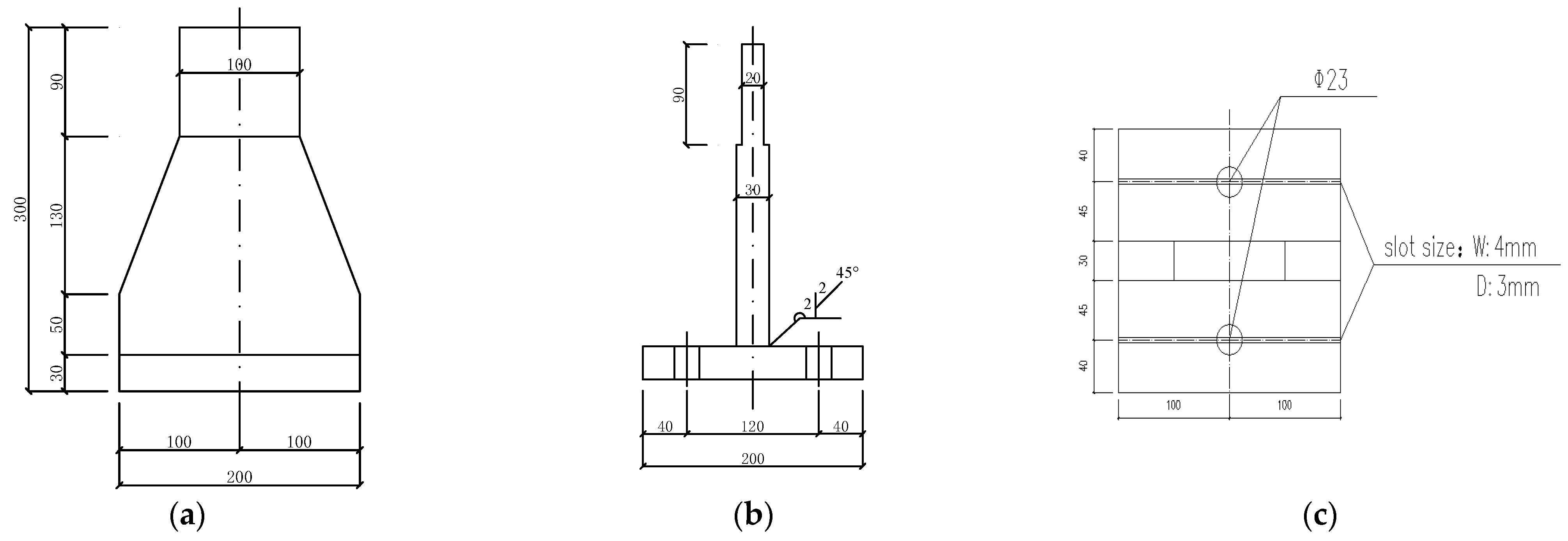
The self-made T-shaped connector was designed and employed to ensure an axial tension of M20 torque shear high-strength bolts under loading, which is close to the actual engineering scenario. The T-shaped connector made by Q355B steel is shown in Figure 2. V-shaped groove welding was adopted with grade one welding. The upper surface of the T-shaped connector base plate is grooved with a 4-mm depth and 3-mm width, which is used to place the strain gauge to connect the wire of the strain gauge. Two high-tensile bolts were tested at the same time considering the long time period of the fatigue test.

2.2. Material Testing

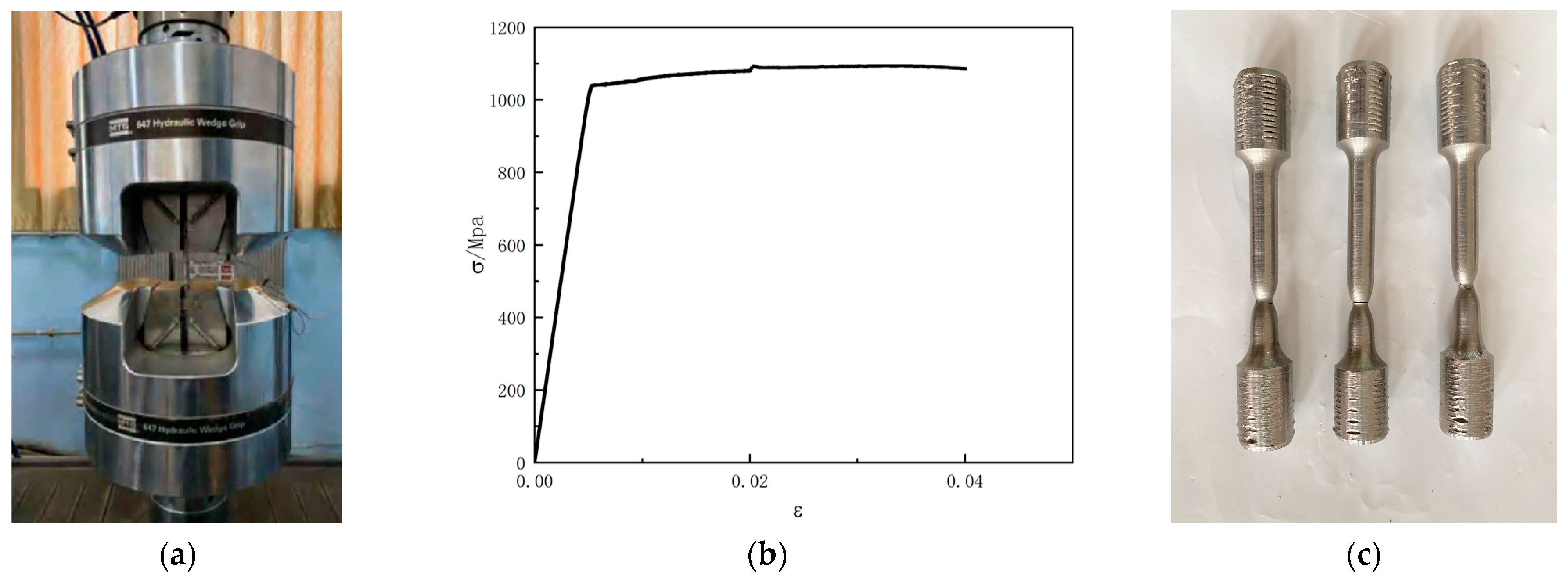
To obtain material properties, a total of 3 tensile tests were conducted using a WAW-2000 electro-hydraulic servo universal testing machine in accordance with ISO 6892-1 [18]. Three high-tensile bolts were randomly selected and machined into standard samples for static tensile tests, as shown in Figure 3. The measured material properties are tabulated in Table 1, including the yield stress (σ0.2), Young’s modulus (E), elongation rate and shrinkage rate. The material properties were then used to conduct numerical simulation afterwards. The full stress-strain curve for the material under the static loading is shown in Figure 4.

2.3. Testing-Rig and Loading Procedure

The constant-amplitude fatigue tests were performed using the MTS Landmark 370.50 hydraulic servo fatigue test machine (MTS) which had a 500 kN capacity, as shown in Figure 5. Before monitoring and collecting the bolt strain value, the symmetrical positions on both sides of the bolt rod were cleaned and polished, and the strain gauge was pasted. The contact surface of the T-shaped connector was vertically aligned, and two M20 torque shear high-strength bolts were screwed into the bolt holes. They were fixed with the clamp of the MTS testing machine to ensure the alignment and axiality. The testing equipment kept track of the bolt’s strain and the number of cycles throughout the test. When the bolt totally snapped, the MTS machine halted itself. The damaged bolt was identified and photographed, along with the total number of cycles and other details. The fatigue test’s objective was to create S-N curves for analysis of the constant-amplitude fatigue behavior of M20 torque shear high-strength bolts.

2.4. Experimental Results

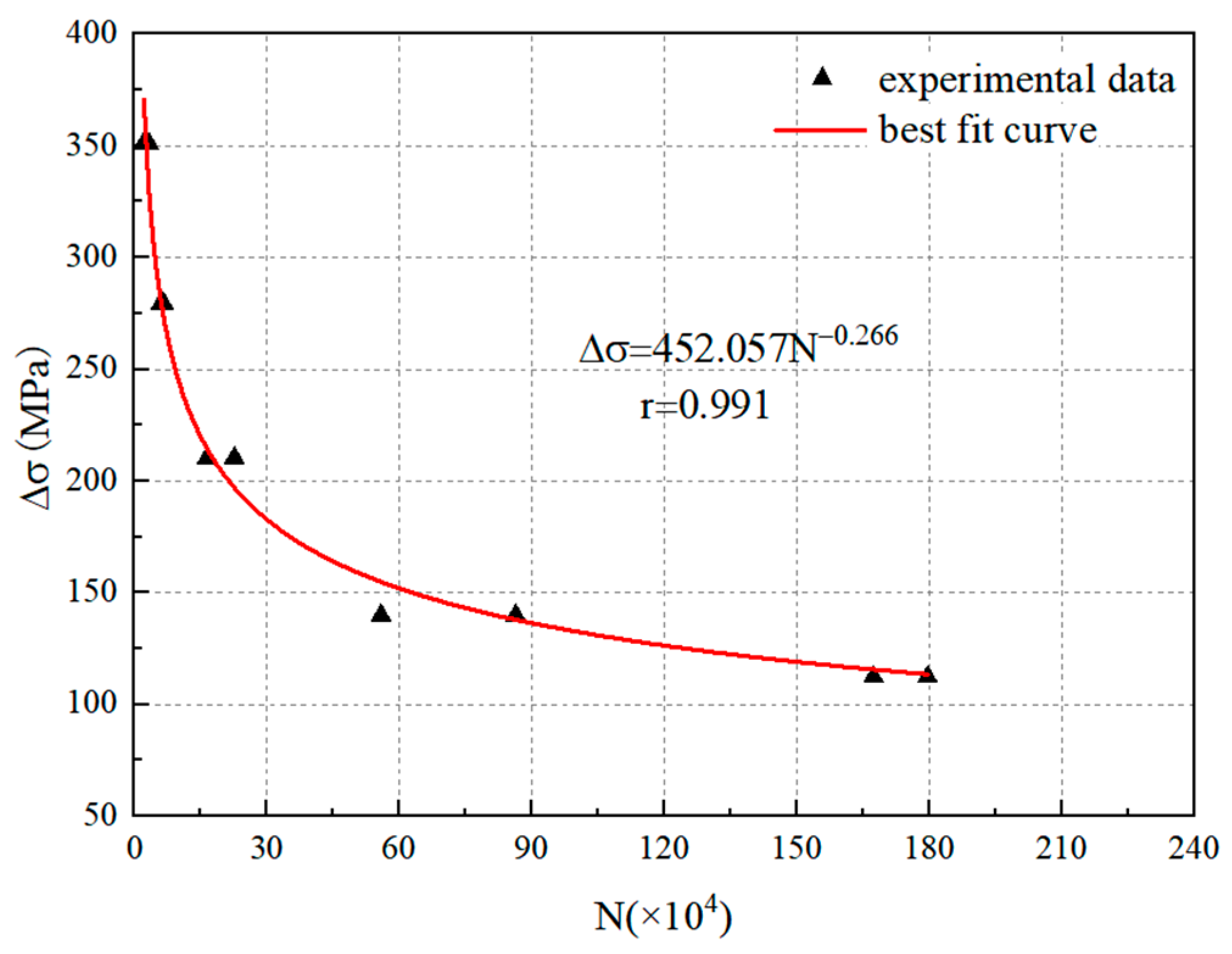
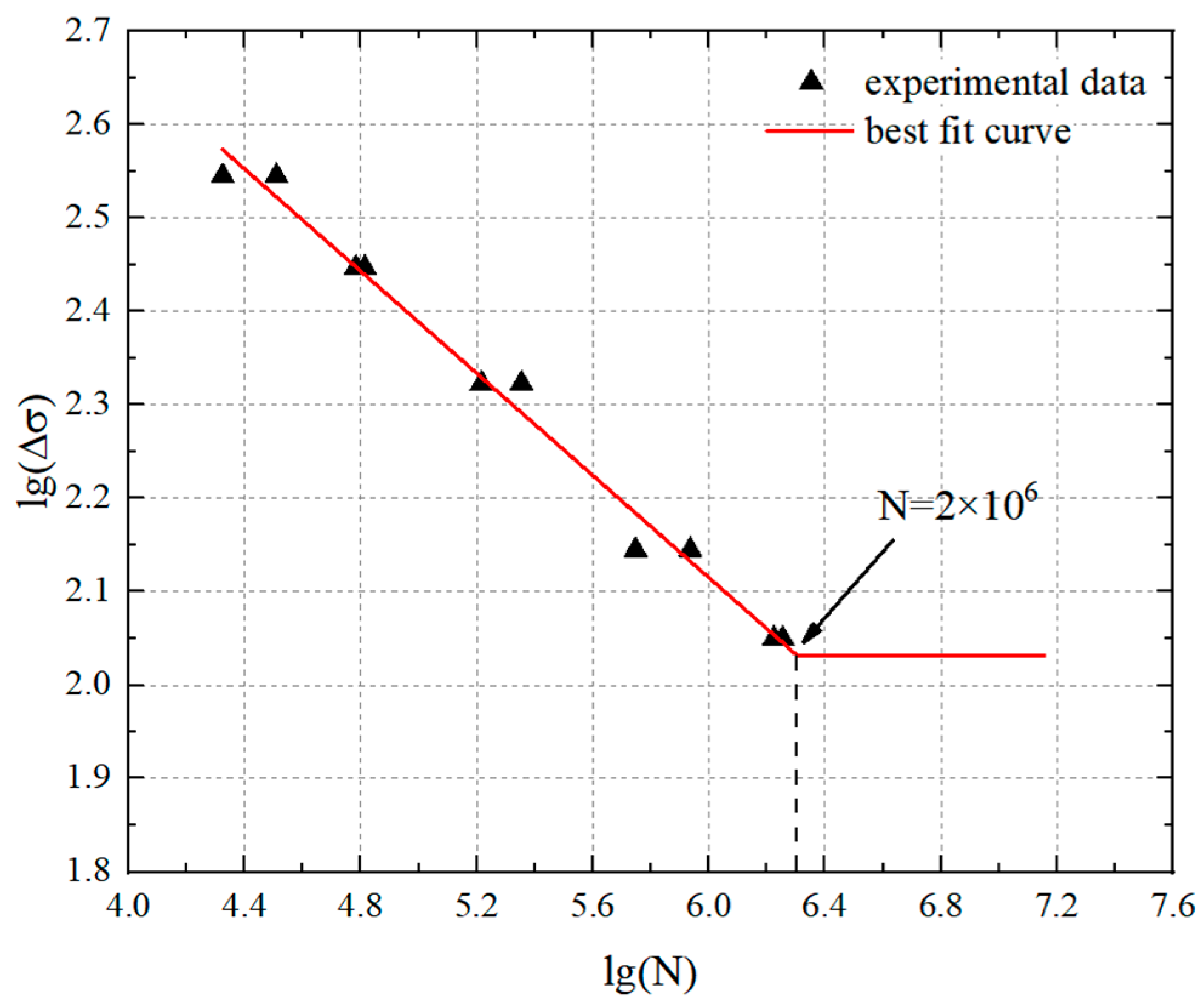
Ten M20 torque shear high-strength bolts were subjected to axial fatigue tests. Each high-tensile bolt fractured at the first exposed thread’s root. The results of cyclic load times are summarized in Table 2. Taking the stress amplitude as the parameter, the constant-amplitude power regression curve and fatigue S-N curve are presented in Figure 6 and Figure 7, respectively.
The corresponding equation of the S-N curve with a 95% confidence interval for M20 torque shear high-strength bolts without pretension is:
lg ( N ) = 13.633 3.613 lg ( Δ σ ) ± 0.165
where Δ σ   is the nominal stress amplitude of loading, and N is the number of stress cycles. Note that a high correlation coefficient r between lg(N) and lg( Δ σ ) equal to −0.994 is obtained.

3. Numerical Study

A simplified finite element model was established to study the stress distribution and stress concentration of the bolts using the ABAQUS software [19]. Bolts are typical notched components. Due to the presence of notches, stress concentration is generated under the action of external forces, resulting in the local high stress at the notches and forming weak parts. The thread root hot-spot thread can be determined through simulation analysis. A similar modelling technique was also used by Jiao et al. [6].

3.1. Development of Finite Element Model

Some simplifications were used to make the computation process easier. Bolts were considered to be made of homogenous, linear elastic, and isotropic material. This finite element model took into account the high-strength bolt’s material parameters as determined from the tensile test. The Poisson’s ratio was set as 0.3, and the Young’s modulus was set as 2.086 × 10⁵ MPa. The identical load and boundary conditions used in the applied experimental tests were used. While the upper clamp of the loading device was free to move vertically, the bottom clamp’s end was fixed. Both the contact between the bolt and loading device as well as the contact between the bolt thread and nut were discretized using the surface-to-surface approach. Hard contact was chosen as the interaction feature for normal behavior, while the coulomb friction model with a 0.1 friction coefficient was used for tangential behavior [19,20].
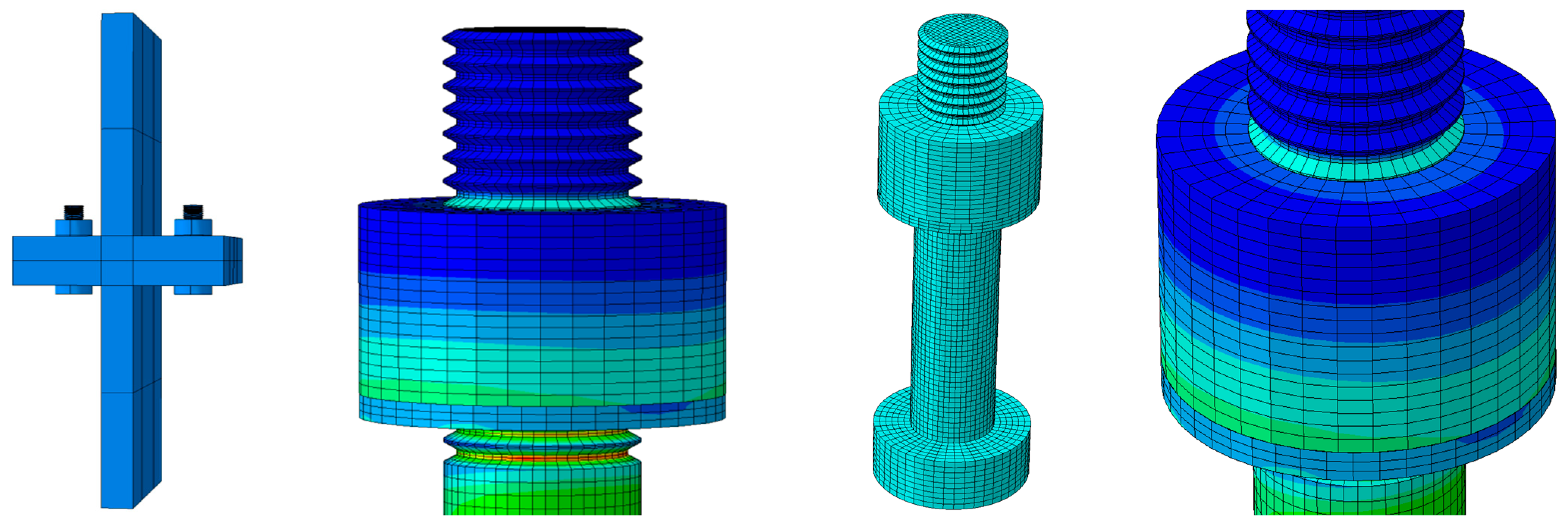
The threaded part was simulated using secondary reduction integral elements (C3D20R), and the rest using linear reduced integral elements (C3D8R) [19]. To improve the analysis accuracy, the mesh size of the bolt rod was set as 2 mm, while the mesh size of the other components was 8 mm, as shown in Figure 8. The upper end of the T-shaped piece was set as a fixed-end constraint, and the external force was loaded as a concentrated force at the lower position of the lower T-shaped piece.

3.2. Numerical Results

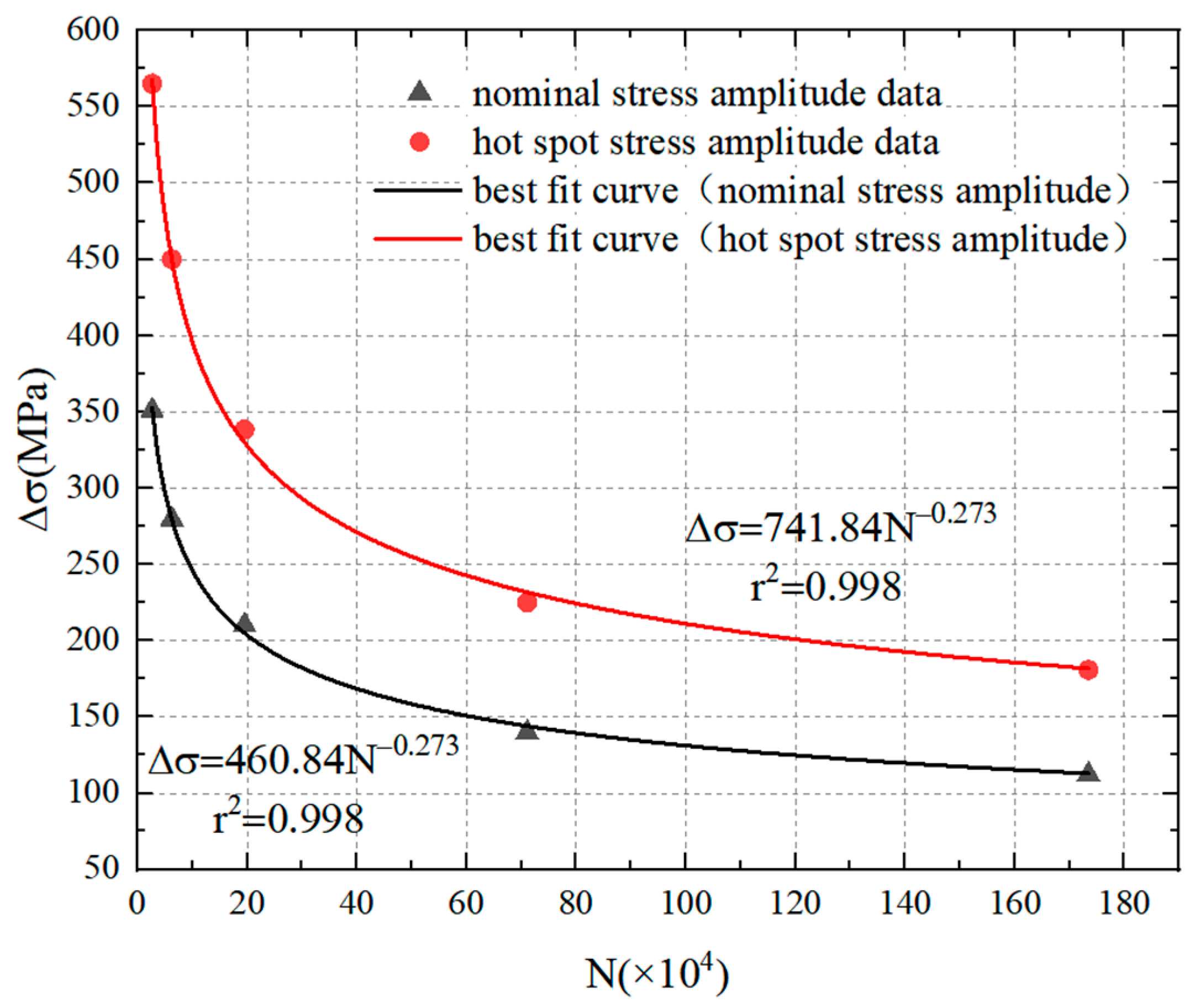
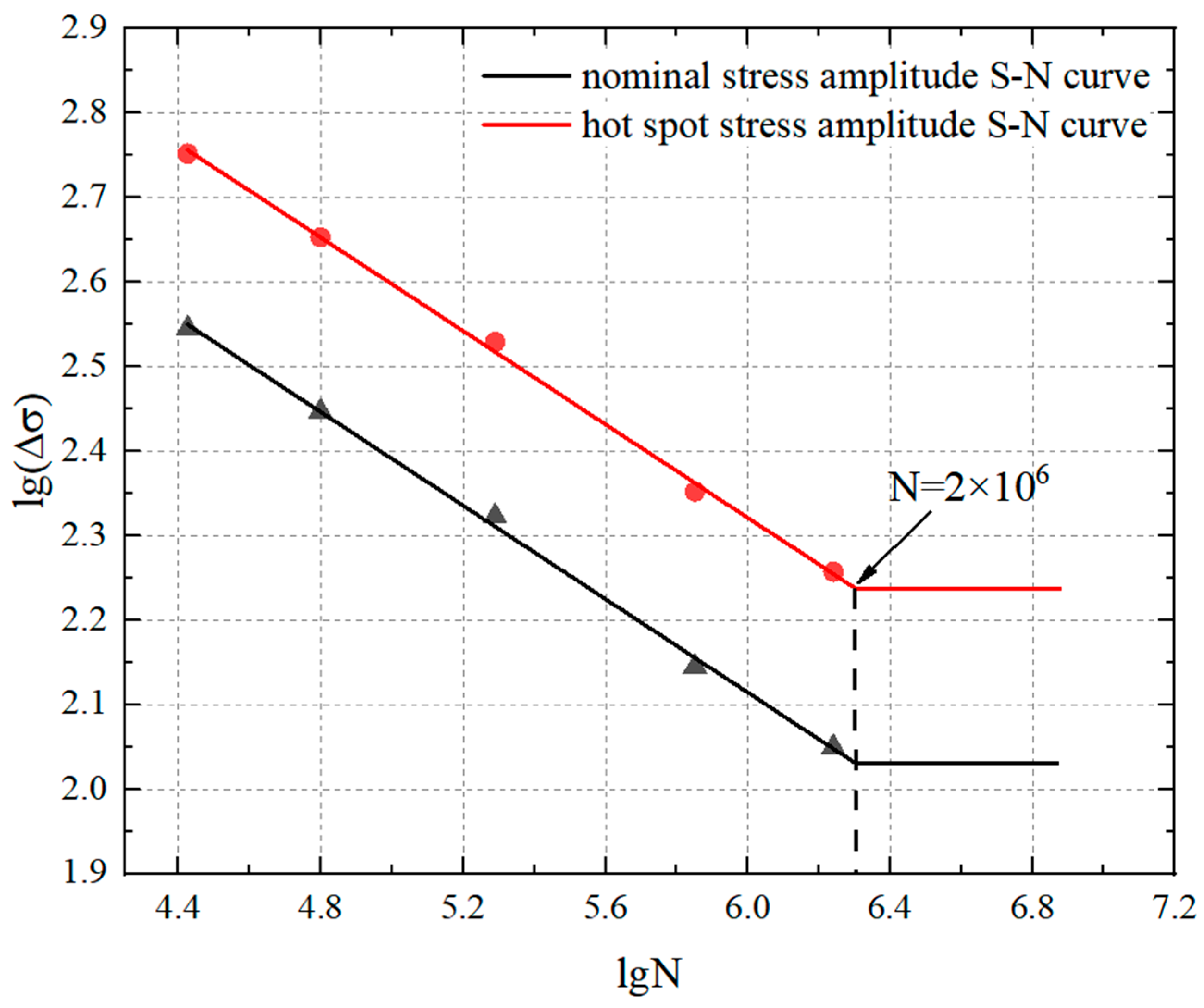
Ten M20 high-tensile bolts under different external forces were simulated using the ABAQUS software [19]. The hot-spot stress method, also known as the geometric stress method, takes into account the effect of member geometry and may be a more accurate reflection of the true stress state for bolts with threads. The corresponding hot-spot stress and the amplitude were obtained in Table 3. The maximum stress for each bolt was located at the root of the first exposed thread according to the stress nephogram. The fracture positions of the bolts were the same as those of the experimental results. This finding was consistent with the previous studies. The power regression curve and S-N curve were established by using the hot-spot stress and nominal stress amplitudes as parameters, as presented in Figure 9 and Figure 10. Under the same external load, the allowable nominal stress amplitude of M20 torque shear high-strength bolts is approximately 0.625 times the allowable hot-spot stress amplitude. The nominal stress amplitude is calculated from the nominal diameter of the high-tensile bolt, resulting in a considerably smaller nominal stress amplitude. The comparison shows that using the normal stress amplitude as the parameter in the traditional calculation method for the torque shear high-strength bolts is conservative. Comparatively, it is more accurate to calculate the fatigue strength and the fatigue life by using the hot-spot stress amplitude as the parameter.
The equation corresponding to the double logarithmic S-N curve of hot-spot stress amplitude with 95% confidence interval for M20 torque shear high-strength bolts without pretension is as follows:
lg ( N ) = 14.42 3.623 lg ( Δ σ h ) ± 0.728
where Δ σ h is the hot-spot stress amplitude, and N is the number of cycles. Note that a high correlation coefficient r between lg(N) and lg( Δ σ h ) equal to −0.999 is obtained.

4. The Calculation Method for Constant-Amplitude Fatigue

4.1. Allowable Nominal Stress Amplitude

A previous study reported by Yang et al. [4] suggested that the main factor that affects the fatigue strength of M20 torque-shear high strength bolts was the stress amplitude, instead of the stress ratio or the maximum stress. Therefore, the allowable nominal stress amplitude ( Δ σ ) was used as the design parameter to establish the first calculation method for determining the constant-amplitude fatigue for M20 torque-shear high strength bolts as follows:
Δ σ     [ Δ σ ]
Δ σ = C N 1 / β
where Δ σ is the high-tensile bolted connection’s nominal stress amplitude (MPa), [ Δ σ ] is the allowable nominal stress amplitude (MPa), C and β are parameters, the values of which are 5.45 × 10¹³ and 3.6712; and the number of cycles is N.
Taking N = 2 × 10⁶ as the initial number of stress cycles, the allowable nominal stress without pretension of M20 high-tensile bolts is 96.371 MPa, based on Equation (2). Taking N = 2 × 10⁶ as the initial number of stress cycles, the allowable hot-spot stress amplitude of M20 high-tensile bolts without pretension calculated is 109.651 MPa. A similar calculation method was adopted by Yang et al. [4] and further details can be found in Ref. [4].

4.2. Allowable Hot-Spot Stress Amplitude

The second calculation method was based on the hot-spot stress amplitude ( Δ σ h ), which was used as the design parameter to establish the calculation method for determining the constant-amplitude fatigue for M20 torque-shear high strength bolts. Both sides of Equation (3) are multiplied by the fatigue notch factor K f , using Equation (5) as given below:
Δ σ h   = K f Δ σ [ Δ σ h ]
Based on a significant number of test data, Zhao [7] proposed the calculation formula of fatigue notch factor using Equation (6) as given below:
K t K f = 0.88 + A Q b
where in this study, values of Q, A, and b are 4.492, 0.290, and 0.152, respectively. K t is the theoretical stress concentration factor, taken as 3.672. Thus, the K f value is obtained as 2.951. The allowable hot-spot stress amplitude of M20 high-tensile bolts without pretension [ Δ σ h ] is 283.296 MPa, taking N = 2 × 10⁶ as the initial number of stress cycles.

4.3. Results and Discussion

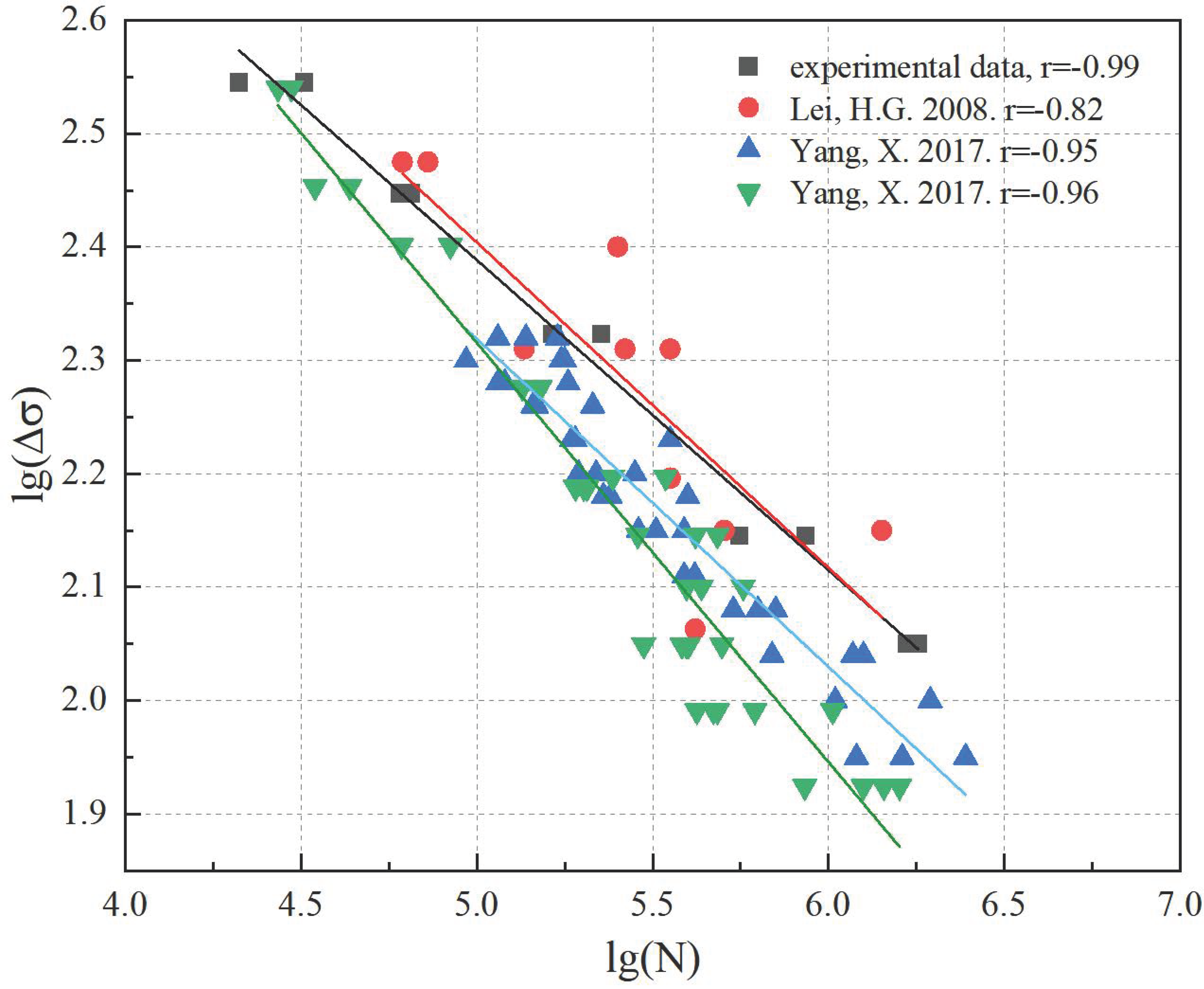
Generally, the fatigue performance of materials can be investigated using the relationship between the stress range and fatigue life. Taking the nominal stress amplitude as the parameter, the power regression curve and S-N curve were established, as shown in Figure 11 and Figure 12. The constant-amplitude fatigue of M20 torque shear high-strength bolts for fabricated structures and high-tensile bolts in grid structures were compared. It can be seen that the fatigue data discreteness of the two is small, and the fatigue curve fit is high. The fatigue performance of high-tensile bolts and M20 torque shear high-strength bolts with different diameters were compared. Under two million load cycles, the nominal stress amplitude difference of two types of high-tensile bolts with the same diameter is large, while the hot-spot stress amplitude difference is small. The differences in appearance and shape of the two types of high-tensile bolts result in different stress concentration factors and thus different fatigue notch factors. To evaluate the real fatigue performance of high-tensile bolts, a fatigue design criterion can be established by using the hot-spot stress amplitude as the parameter. The comparison between the same type of high-tensile bolts suggests that the allowable stress amplitude decreases with the increasing diameter of high-tensile bolts.
The S-N curve equations of high-tensile bolts are summarized in Table 4. It can be concluded that the allowable nominal stress amplitude under two million loading cycles ([ Δ σ ]2×10⁶) of M20 torque shear high-strength bolts is 96.37, which is approximately 1.38 to 2.36 times that of the high-tensile bolts investigated in Refs. [1,2]. In addition, the allowable hot-spot stress amplitude of the M20 torque shear high-strength bolts under two million loading cycles ([ Δ σ h ]2×10⁶) is 0.93 to 1.59 times than that of the high-tensile bolts used in Refs. [1,2]. It can be concluded that the hot-spot stress amplitude should be used, as the fatigue notch factors of the two high-tensile bolts are different.

5. Comparison of Existing Design Specifications

The S-N curve of M20 torque shear high-strength bolts was determined based on the results obtained from the constant-amplitude fatigue tests. The allowable stress amplitude in this study is 96 MPa. GB50017 and Eurocode 3 have the same allowable stress amplitude; both are 50 MPa. The ANSI/AISC 360-16 allowable stress amplitude is small, 48 MPa. The allowable stress amplitude of M20 torque shear high-strength bolts under two million load cycles is twice the design value obtained from ANSI/AISC 360-16 [16], and 1.93 times the design value obtained from Eurocode 3 [17] and GB 50017 [15], respectively. These indicate that the existing design standards [15,16,17] are relatively conservative for predicting the fatigue performance of such bolts. The comparison of fatigue strength values obtained with this study and different design codes [15,16,17] is summarized in Table 5.

6. Fatigue Fracture Analysis

In this study, three bolts (M20-1, M20-3, and M20-10) were selected for fatigue fracture analysis, and the irreversible deformation of the bolts was recorded. The Phenom ProX electron microscope energy spectrum integrated machine was employed to image macro-fractures, as shown in Figure 13 and Figure 14. The results suggested that the stress amplitude of M20-1, M20-3 and M20-10 was 351.02 MPa, 279.59 MPa and 112.25 MPa, respectively. The influence of stress amplitude on the fatigue fracture of high-tensile bolts can be evaluated by analyzing the fatigue fracture under different stress amplitudes.
The typical fatigue fracture of bolts is presented in Figure 13a. There was a distinct boundary between the extension and the transient fracture zones, and the fracture was relatively neat and smooth. The cracks initiated from a single fatigue source formed a fan propagation zone, and finally fractured. The area of the transient fracture zone accounted for approximately 1/3 of the total fracture area. Microscopically, there are obvious river-like strips in the initiation zone, and the layers are pushed outward, as shown in Figure 13b. The secondary crack in the extension zone is relatively deep and dense; it is formed by the expansion of a quasi-cleavage fracture along a certain crystalline surface, indicating that the blot is subjected to greater stress, and small holes can also be observed in the extension zone, as shown in Figure 13c. Observing the characteristics of the transient fracture zone, the existence of the circular hollow dimple left on the fracture during fracture reflects the plastic deformation of the bolt when it is broken; the dimples are densely distributed in the transient zone, Small dimples are honeycomb in shape and are distributed around a large dimple, as shown in Figure 13d. This indicates that the fatigue fracture of the bolt is a plastic fracture.
Figure 14a shows a fracture with a single fatigue source. The cracks propagated from the fatigue initiation zone to the periphery to form a crescent-shaped extension zone. The area of the transient fracture zone was relatively large, occupying approximately 3/5 of the total fracture zone. The deepest part of the transient fracture zone was located in the middle part of the fracture, while the depth of downward sag was relatively large. There was also a small transient fracture zone to the right of the main transient fracture zone, which was a small area where a rupture occurred. Microscopically, cracks start at the center point of the fatigue pattern radioactive source, damage occurs on the surface, cracks spread from the initiation zone to form wavy fine lines, and there are some fine holes scattered in the initiation zone, as shown in Figure 14b. Many secondary cracks can be observed in the extension zone, as shown in Figure 14c. The microscopic morphology of the transient fracture zone is shown in Figure 14d, and it can be observed that the dimple is not obvious, not as dense as the M20-1 transient zone, and there are some small honeycomb-like dimples.
Figure 15a shows a single fatigue initiation zone macroscopically. The cracks initiated from the initiation zone and propagated to the periphery, forming many step-shaped stripes with varying lengths along the edges. All the stripes pointed towards the center of the final transient fracture zone. The fracture zone’s area was smaller than that of the first two fractures in Figure 12 and Figure 13, occupying 1/4 of the total fracture zone. Microscopically, the dividing line of the steps can be clearly observed, and there are many small holes around the initiation zone, which may be impurities. as shown in Figure 15b. In the extension zone, it can be found that there are many fatigue steps and secondary cracks, although the secondary cracks are deeper but the length is much more regular than that of M20-3. A small number of cleavage facets are distributed in the extension zone, and a small number of fatigue bands can be observed, as shown in Figure 15c. In the transient fracture zone, both large equiaxed dimples and dense small dimples were observed, as shown in Figure 15d. The number of honeycomb dimples increased significantly, when compared with that of the M20-3 bolt.
Through the comparative analysis of the fractures of high-tensile bolts, the following conclusions can be obtained: (a) The area of the fracture transient zone increases as the stress amplitude of the bolt increases. (b) As the stress amplitude increases, the larger the fatigue glow spacing between the fracture initiation zone and the expansion area on the microscopic level, the longer and deeper the secondary crack, and the easier it is to produce fatigue steps. (c) The dimple is generated and aggregated with the three-way stress of the crack tip, and after the tensile stress reaches the critical point of yield deformation of the component, the component fractures to form circular or oval voids of different sizes.

7. Concluding Remarks

This study conducted a total of 10 constant-amplitude fatigue experiments to study the fatigue performance of M20 torque shear high-strength bolts. In addition, a numerical model was established to further study the stress distribution of the bolts. To evaluate the accuracy and reliability of the existing design standard, comparisons between test results with design values obtained from GB 50017(2017), ANSI/AISC 360-16 (2010) and Eurocode 3 (2003) were established. The following conclusions could be drawn based on the findings from the numerical analysis and experiments
(1)
The fatigue performance, stress concentration and fracture analysis were analyzed. The allowable nominal stress amplitude of M20 torque-shear type high-strength bolts was 96.371 MPa, while the allowable hot-spot stress amplitude was 283.296 MPa.
(2)
Upon comparison, it was found that the allowable stress amplitude of M20 torque shear high-strength bolts is twice the design value obtained from ANSI/AISC 360-16 (2016), and 1.93 times the design value obtained from Eurocode 3 (2005) and GB 50017 (2017). These indicate that the existing design standards are relatively conservative for predicting the fatigue performance of such bolts.
(3)
A finite element model was established, and the corresponding hot-spot stress and the amplitude of such bolts were obtained. The numerical results suggested that the maximum stress for each bolt was located at the root of the first exposed thread according to the stress nephogram. The fracture positions of the bolts were the same as those of the experimental results.
(4)
Fatigue fracture analysis was conducted, and the influence of stress amplitude on the fatigue fracture of high-tensile bolts was evaluated by analyzing the fatigue fracture under different stress amplitudes. The results suggested that the stress amplitude of M20-1, M20-3 and M20-10 was 351.02 MPa, 279.59 MPa and 112.25 MPa, respectively.
(5)
The S-N curve of torque-shear high strength bolts under constant-amplitude loading was proposed using the hot-spot stress amplitudes.

8. Future Works

The objective of this study was to simulate the most unfavorable situation of complete loss of bolt preload in actual engineering, and different preload forces will be applied for comparison in subsequent studies.

Author Contributions

Conceptualization, L.Z.; methodology, L.Z.; software, Y.S.; validation, S.Z.; formal analysis, L.Z.; investigation, L.Z.; resources, L.Z.; data curation, Z.Z.; writing—original draft preparation, L.Z.; writing—review and editing, L.Z.; visualization, L.Z.; supervision, H.L.; project administration, H.L.; funding acquisition, H.L. All authors have read and agreed to the published version of the manuscript.

Funding

This research was funded by [LeiHonggang] grant number [51578357] And The APC was funded by [LeiHonggang].

Institutional Review Board Statement

Not applicable.

Informed Consent Statement

Not applicable.

Data Availability Statement

The data used to support the findings of this study are available from the corresponding author upon request.

Conflicts of Interest

The authors declared no potential conflict of interest with respect to the research, authorship, and publication of this paper.

References

  1. Lei, H.G. The Theoretical and Experimental Research on Fatigue Performance of High Strength Bolt Connection in Grid Structure with Bolt Sphere Joint. Ph.D. Thesis, Taiyuan University of Technology, Taiyuan, China, 2008. [Google Scholar]
  2. Yang, X. The Theoretical and Experimental Research on Fatigue Performance of m30 and m39 High Strength Bolts in Grid Structures with Bolt Sphere Joints. Ph.D. Thesis, Taiyuan University of Technology, Taiyuan, China, 2017. [Google Scholar]
  3. Qiu, B.; Yang, X.; Zhou, Z.; Lei, H.G. Experimental study on fatigue performance of M30 high-strength bolts in bolted spherical joints of grid structures. Eng. Struct. 2020, 205, 110123. [Google Scholar] [CrossRef]
  4. Yang, X.; Lei, H.G.; Chen, Y.F. Constant amplitude fatigue test research on M20 high strength bolts in grid structure with bolt-sphere joints. Adv. Struct. Eng. 2016, 20, 1466–1475. [Google Scholar] [CrossRef]
  5. Yang, X.; Lei, H.G. Constant amplitude fatigue test of high strength bolts in grid structures with bolt-sphere joints. Steel Compos. Struct. Int. J. 2017, 25, 571–579. [Google Scholar] [CrossRef]
  6. Jiao, J.; Liu, Z.; Guo, Q.; Liu, Y.; Lei, H.G. Constant-amplitude fatigue behavior of m24 high-strength bolt of end-plate flange connection. Structures 2021, 34, 2041–2053. [Google Scholar] [CrossRef]
  7. Zhao, S.B. Fatigue-Resistant Design: A Handbook; Machinery Industry Press: South Norwalk, CT, USA, 2015. [Google Scholar]
  8. Lochan, S.; Mehmanparast, A.; Wintle, J. A review of fatigue performance of bolted connections in offshore wind turbines. Procedia Struct. Integr. 2019, 17, 276–283. [Google Scholar] [CrossRef]
  9. Zhou, Z.C.; Lei, H.G.; Qiu, B.; Zhang, S.; Wang, G.Q. Experimental study on fatigue performance of m60 high-strength bolts with a huge diameter under constant amplitude applied in bolt–sphere joints of grid structures. Appl. Sci. 2022, 12, 8639. [Google Scholar] [CrossRef]
  10. Nam, J.; Kim, D.; Kim, K.; Choi, S.; Oh, J.H. Unified fatigue life prediction of bolts with different sizes and lengths under various axial loading conditions. Eng. Fail. Anal. 2022, 131, 105841. [Google Scholar] [CrossRef]
  11. Maljaars, J.; Euler, M. Fatigue S-N Curves of bolts and bolted connections for application in civil engineering structures. Int. J. Fatigue 2021, 151, 106355. [Google Scholar] [CrossRef]
  12. Lotsberg, I.; Sigurdsson, G. Hot spot stress SN curve for fatigue analysis of plated structures. J. Offshore Mech. Arct. Eng. 2006, 128, 330–336. [Google Scholar] [CrossRef]
  13. Redondo, R.; Mehmanparast, A. Numerical analysis of stress distribution in offshore wind turbine m72 bolted connections. Metals 2020, 10, 689. [Google Scholar] [CrossRef]
  14. Nah, H.S.; Choi, S.M. Evaluate the clamping force of torque-shear high strength bolts. Int. J. Steel Struct. 2018, 18, 935–946. [Google Scholar] [CrossRef]
  15. GB50017-2017; Code for Design of Steel Structures. China Architecture and Building Press: Beijing, China, 2017.
  16. ANSI/AISC 360–16; Specification for Structural Steel Buildings. American Institute of Steel Construction: Chicago, IL, USA, 2016.
  17. EN 1993-1-9; Eurocode 3: Design of Steel Structures-Part 1-9: Fatigue. European Union: Maastricht, The Netherlands, 2005.
  18. ISO 6892-1; Metallic Materials–Tensile Testing–Part 1: Method of Test at Room Temperature. International Standard: Geneva, Switzerland, 2019.
  19. ABAQUS. Analysis User’s Manual-Version 6.14-2; ABAQUS Inc.: Palo Alto, CA, USA, 2018. [Google Scholar]
  20. Gui, X.W.; Zhang, J.D.; Liao, R.D. Finite element simulation study of bolt preload process. Strength Environ. 2021, 48, 9–16. [Google Scholar]
Figure 1. Torque-shear high strength bolts investigated in this study. (a) Dimensions. (b) A photograph.
Buildings 13 00367 g001
Figure 2. Details of the T-shaped connector (unit: mm). (a) Left view. (b) Front view. (c) Plan view.
Buildings 13 00367 g002
Figure 3. Dimensions and a photograph of test specimens (unit: mm). (a) Dimensions. (b) A photograph.
Buildings 13 00367 g003
Figure 4. Static tensile tests. (a) Test setup. (b) Full stress-strain curve. (c) Failure mode.
Buildings 13 00367 g004
Figure 5. Photograph of constant-amplitude fatigue tests.
Buildings 13 00367 g005
Figure 6. Power regression curve of M20 torque-shear HSBs.
Buildings 13 00367 g006
Figure 7. S-N curve of M20 torque-shear HSBs.
Buildings 13 00367 g007
Figure 8. Development of FE models using ABAQUS.
Buildings 13 00367 g008
Figure 9. Power regression curves.
Buildings 13 00367 g009
Figure 10. S-N curves of M20 torque-shear HSBs.
Buildings 13 00367 g010
Figure 11. Power regression curves of high-tensile bolts.
Buildings 13 00367 g011
Figure 12. S-N curves of high-tensile bolts.
Buildings 13 00367 g012
Figure 13. Fatigue macro-fractures of M20 torque-shear HSBs. (a) Macro-view fracture. (b) 300 times initiation zone. (c) 500 times extension zone. (d) 5000 times fracture zone.
Buildings 13 00367 g013
Figure 14. Fatigue macro-fractures of M20 torque-shear HSBs. (a) Macro-view fracture. (b) 300 times initiation zone. (c) 1000 times extension zone. (d) 5000 times fracture zone.
Buildings 13 00367 g014
Figure 15. Fatigue macro-fractures of M20 torque-shear HSBs. (a) Macro-view fracture. (b) 300 times initiation zone. (c) 5000 times extension zone. (d) 5000 times fracture zone.
Buildings 13 00367 g015
Table 1. Measured material properties of bolts.
Specimen
No.
Strength (MPa)Elastic Modulus (GPa)Elongation
Rate
Shrinkage
Rate
σ 0.2 σ ¯ 0.2 σ b σ ¯ b E E ¯ δ(%) δ ¯ (%) ψ(%) ψ ¯ (%)
M20-a1016.41022.41090.41097.1209.6208.610.010.842.242.3
M20-b1028.11094.3205.710.342.1
M20-c1022.61106.7210.612.242.7
Table 2. Test results of constant amplitude fatigue of M20 torque shear high-strength bolts without pretension.
Serial No.Tension (kN)Nominal Stress (MPa)Stress Amplitude (MPa)Frequency (Hz)Number of Cycles
FmaxFminσmaxσmin Δ σ lg ( Δ σ ) N (×104)lg(N)
112337502.04151.02351.022.54552.10684.324
212337502.04151.02351.022.54553.22804.509
39829.5400.00120.41279.592.44756.06244.783
49829.5400.00120.41279.592.44756.52274.814
573.522300.0089.80210.202.323522.59735.354
673.522300.0089.80210.202.323516.43805.216
74914.75200.0060.20139.802.145755.84065.747
84914.75200.0060.20139.802.145786.32805.936
939.2511.75160.2047.96112.242.0507167.35456.224
1039.2511.75160.2047.96112.242.0507179.59466.254
Table 3. Hot-spot stress and hot-spot stress amplitude of M20 torque-shear HSBs without pretension.
Serial No.Nominal Stress (MPa)Hot-Spot Stress (MPa)Nominal Stress
Amplitude (MPa)
Hot-Spot Stress
Amplitude (MPa)
Number of Cycles
σmaxσmin σ h max σ h min Δ σ lg ( Δ σ ) Δ σ h lg ( Δ σ h ) N (×104)lg(N)
1502.04151.02808.39243.33351.022.54565.052.752.664.42
2400.00120.41644.04194.03279.592.44450.002.656.294.79
3300.0089.80482.97144.73210.202.32338.242.5219.515.29
4200.0060.20322.0797.10139.802.14224.972.3571.085.85
5160.2047.96258.1077.39112.242.05180.712.25173.476.24
Table 4. Summary of S-N curves of high-tensile bolts [1,2].
Type of BoltsS-N Equation [ Δ σ ] 2×10⁶ [ Δ σ h ] 2×10⁶
M20 bolts used in this studylg(N) = 13.633 − 3.613lg( Δ σ ) ± 0.16596.37283.29
M20 bolts [1]lg(N) = 13.2414 − 3.4483lg( Δ σ ) ± 0.57870.04304.69
M30 bolts [2]lg(N) = 12.2205 − 3.0872lg( Δ σ ) ± 0.455458.91256.26
M39 bolts [2]lg(N) = 10.8511 − 2.5131lg( Δ σ ) ± 0.502840.82177.57
Table 5. Comparison of fatigue strength values obtained with this study and different design codes [15,16,17].
Design MethodsEquationAllowable Stress Amplitude
ANSI/AISC 360-16 [16] F S R = 6900 C f n S R 0.333 F T H 48
Eurocode 3 [17] Δ σ R m · N = Δ σ C m · 2 × 10 6 50
GB50017 [15] Δ σ = C N 1 / β 50
This study---96
Disclaimer/Publisher’s Note: The statements, opinions and data contained in all publications are solely those of the individual author(s) and contributor(s) and not of MDPI and/or the editor(s). MDPI and/or the editor(s) disclaim responsibility for any injury to people or property resulting from any ideas, methods, instructions or products referred to in the content.