

CFD Analysis for a New Trombe Wall Concept
by
 , ,
, ,
Alexandru Mihai Bulmez
*,
Alin Ionuț Brezeanu
,
George Dragomir
,
Mariana Fratu
,
Nicolae Fani Iordan
,
Sorin Ionuț Bolocan
,
Lucian Rozorea
,
Eugen Călin Popa
and
Gabriel Năstase
Department of Building Services, Faculty of Civil Engineering, Transilvania University of Brasov, 500152 Brasov, Romania
*
Author to whom correspondence should be addressed.
Buildings 2024, 14(3), 579; https://doi.org/10.3390/buildings14030579
Submission received: 15 January 2024
/
Revised: 14 February 2024
/
Accepted: 20 February 2024
/
Published: 21 February 2024
(This article belongs to the Special Issue Thermal Fluid Flow and Heat Transfer in Buildings)
Highlights
What are the main findings?
- A numerical investigation for conjugate-heat and flow-heat transfer, turbulent flow, and solar radiation for a Trombe wall design.
- Results for four studied cases, for two cities with or without solar radiation.
What is the implication of the main finding?
- New Trombe wall design for indoor ventilation purposes.
- Year-round study of the new Trombe wall behavior in two cities.
Abstract
:The envelope (façade) of a building is the first barrier between the exterior and the interior of the building and withstands the highest variation in temperature and solar radiation. Trombe walls are used to take advantage of that and contribute to the heating of interior air, helping the heating system. In this study, a new Trombe wall design is presented to contribute significantly to the indoor ventilation of residential buildings. For this, an exterior wall equipped with a proposed Trombe system was studied in a numerical simulation analysis. The proposed systems consist of two important sections, an exterior one and an interior one. The air cavities on the exterior of the wall, covered with silica glass, are the first heat-transfer layer. The secondary layer used for heat transfer, on the interior, is comprised of a MPCLB wall of 115 mm. The air circulation from the exterior to the interior was established as forced convection with a ventilator. The air circulates through the first heating layer on the exterior air cavities and then passes through the second heating layer on the interior MPCLBs. Two cities in Romania were considered to represent the coldest and hottest climates in Romania. Brașov represents the cold climate and Constanța represents the hot climate. In the investigation, both the presence and absence of solar radiation were taken into account. In total, four cases were established. For all four cases, monthly research was made using monthly mean temperatures, and direct and diffuse solar radiation. The results are promising and illustrate that the system works best during the transitional seasons of spring and autumn. The lower the outdoor temperature, the higher the temperature can be increased. Overall, solar radiation accounted for an average 2 °C increase. The temperature increase varied between 3.4 °C and 15.99 °C for Brașov and between 6.42 °C and 12.07 °C in Constanța. This study presents an alternative way to use the Trombe wall for indoor ventilation purposes throughout the year, compared to traditional uses for the Trombe wall for indoor heating.
1. Introduction
A Trombe wall constitutes a solar-oriented architectural element situated on the southern facade of a structure [1]. It serves as a passive façade, adept at absorbing incident solar radiation and subsequently storing this energy to augment the thermal conditions within the buildings through a passive-heating mechanism [2,3,4].
In the pursuit of sustainable and energy-efficient building design, the Trombe wall has emerged as a promising passive solar-heating technology [5,6]. Traditionally employed to absorb and store solar radiation for space heating, this architectural element has now evolved to encompass an innovative dimension—the utilization of heated air for enhanced ventilation within the building envelope. This study searches into the various integrations of Trombe walls, exploring their capacity not only as passive solar heaters but also as contributors to an efficient and sustainable ventilation system.
The energy efficiency and thermal behavior of a Trombe wall, a passive solar-heating system, can be influenced by various design and environmental factors [1]. The effectiveness of a Trombe wall depends on its orientation towards the sun [7]. A south-facing orientation in the Northern Hemisphere (or north-facing in the Southern Hemisphere) maximizes solar exposure. Proper location without shading obstructions is crucial for optimal energy absorption. The choice of materials for the Trombe wall can significantly impact its thermal performance. Materials with high thermal mass, such as masonry or concrete, can store and release heat effectively. The type of glazing used on the outer surface of the Trombe wall affects the amount of solar radiation transmitted [8,9]. Low-emissivity (low-e) glass can help control heat transfer. Integrating a ventilation system that allows for controlled air circulation between the Trombe wall and the interior space is essential. This enhances the transfer of stored heat to the living space as needed. Increasing the thermal mass of the Trombe wall by using dense materials helps store more heat. This stored energy can then be released gradually to maintain a more stable indoor temperature [10]. Adequate insulation on the non-solar side of the Trombe wall minimizes heat loss during the night or periods of low solar radiation. External shading elements or vegetation can be employed to control solar gain and prevent excessive heat buildup. The local climate, including temperature variations and sunlight availability, should be considered in Trombe wall design [11]. Adaptations may be necessary based on the specific climate of the region. Integrating the Trombe wall with other forms of heating, ventilation, and air-conditioning (HVAC) systems can enhance overall energy efficiency. This allows for balanced and responsive indoor climate control. Conducting computer simulations and thermal modelling, such as computational fluid dynamics (CFD) analysis, can help optimize Trombe wall designs by predicting thermal performance under different conditions. By carefully considering these factors and tailoring the Trombe wall design to specific site conditions, it is possible to enhance its energy efficiency and thermal behavior, making it a more effective passive solar-heating system [12].
Brasov and Constanta are two prominent cities in Romania, each with distinct climatic characteristics. Brasov is situated in the central part of Romania, in the Transylvania region. It is surrounded by the Carpathian Mountains and is known for its humid continental climate, which is characterized by cold winters (with nominal outside calculation temperatures of −21 °C) and warm summers. Constanta is located on the Black Sea coast in southeastern Romania and has a humid subtropical climate with influences from the Black Sea, resulting in milder winters (with nominal outside calculation temperatures of −12 °C) and warmer summers compared to Brasov.
This article aims to encourage the use of multi-perforated clay bricks (MPCLBs) for the construction of a Trombe wall to incorporate forced convection for heating the air from the cavity and to promote this as an innovative approach that can contribute to both energy efficiency and improved indoor air quality. The forced convection system can be designed to draw in outside air, preheat it as it passes through the cavity and then through the multi-perforated clay bricks, and in the end, introduce the preheated air into the interior space. This process helps in maintaining a comfortable indoor temperature and reduces the need for additional heating during transition periods. The forced convection system not only contributes to space heating but also facilitates the introduction of fresh, preheated air into the building. This can lead to improved indoor air quality by reducing humidity levels and promoting ventilation [13]. The success of such a system would depend on careful design, integration, and ongoing monitoring for optimal performance. Subsequent experimental and numerical studies are achievable using this new design of the Trombe wall for air ventilation, especially for residential buildings. Further research desire represents another aim of this paper.
The incorporation of heated air from the Trombe wall into the building’s ventilation strategy does not represent a fundamental change in passive solar design, but in the way considered in this study, it offers the potential for improved indoor air quality and thermal comfort. This investigation employs a comprehensive approach, utilizing CFD simulations and analytical assessments to elucidate the dynamic interactions between solar-radiation absorption, air circulation, and thermal comfort within the built environment [14].
This study also aims to present the complex interplay between Trombe wall technology and ventilation dynamics, ultimately contributing to the advancement of sustainable building practices and the evolution of passive solar-design strategies [15], or solar-assistance-design strategies [16,17].
The motivation behind this research stems from the pressing need to address the growing concerns surrounding energy-efficient buildings. Nowadays, the building sector accounts for over 30% of global primary energy consumption and contributes to nearly 30% of the annual greenhouse gas emissions worldwide [18,19,20,21,22]. Despite significant strides in Trombe wall research, a critical gap persists.
This study aims to cover additional possibilities to use the Trombe wall with a different build with the primary purpose and focus being indoor ventilation. Also, compared to a traditional Trombe wall, this configuration allows ventilation not only for the cold season but also for the hot season.
Further ahead, Section 2 describes the numerical simulation process realized with Comsol Multiphysics V6.2, the geometrical model created, the working parameters and boundary conditions, the mathematical equations used by Comsol Multiphysics and the input measured data for exterior temperature and solar radiance for the two locations considered. Afterwards, Section 3 presents the general research results data, and Section 4 details and provides insight into the results.
2. Materials and Methods
To obtain results comparable with residential-use systems, the geometry was designed for a room with one exterior wall with a length of 4 m on the inside. Figure 1 illustrates the geometrical model used for the numerical simulation. In the middle of the wall, a window of 1.2 m height and 1 m width was considered. The basic wall is a 200 mm brick wall with 200 mm thermal insulation on the outside. On both sides of the window, on the exterior, two air cavities with a depth of 50 mm were considered, covered with 10 mm silica glass. On the inside, another brick wall was proposed, made of MPCLBs, to act as a heat exchanger for the air. At the bottom of the room, an air cavity was considered, for the air to pass beneath the window towards the other side of the MPCLB wall. Everything was covered with gypsum board on the interior face. The air circulation considered is forced convection with a fan. On the exterior, an air inlet of 1.5 m length and 0.1 m height is placed on the right side of the wall, at the bottom. On the interior, the air outlet has the same dimensions and is placed on the same side but at the top of the wall.
Air circulation consists of two different parts: the circulation inside the exterior air cavities and the circulation inside the holes of the MPCLBs, on the interior of the wall. Air is aspirated from the exterior entering the wall from the inlet grille, into the right-side air cavity. It makes its move towards the right-side air cavity through two air cavities beneath and above the window that connect the left and right cavities. On the left-side air cavity, at the top of the wall, an air duct 1.5 m in length and 0.1 m in height connects the exterior air cavities with the MPCLB air cavity at the top. At this stage, air enters the second circulation part. It circulates downwards through the holes of 3 columns of MPCLBs and enters the air cavity at the bottom of the wall, forming where it heads to the right side. Then it enters the second time through the holes of another 3 columns of MPCLBs and exists at the top entering the room from the outlet air grille.
A numerical model was established using this geometry using the finite element software COMSOL Multiphysics V6.2. Three physics modules were used: heat transfer in solids and fluids for the conductive and convective heat transfer, turbulent flow for the air circulation, and surface-to-surface radiation for solar radiation on the exterior face of the wall. To reduce the computational requirements and time, the following assumptions were chosen:
- The system was simulated in stationary mode;
- The system was simulated only for air supply;
- The coarse solid mesh coarsening factor (4 out of 9 factors);
- The finer fluid mesh coarsening factor (7 out of 9 factors);
- The outdoor air temperature used is a monthly mean;
- The solar direct and diffuse radiations used are monthly means.
The mesh for the Trombe wall model was studied separately for the solid and fluid domains. The coarsening factors of the meshes were established after a mesh-dependency process. The process started for both domains from a factor of 1 out of 9 while simulating one case. The temperature values were almost constant for the coarse factor of 4 for the solid domain and the finer factor of 7 for the fluid domain.
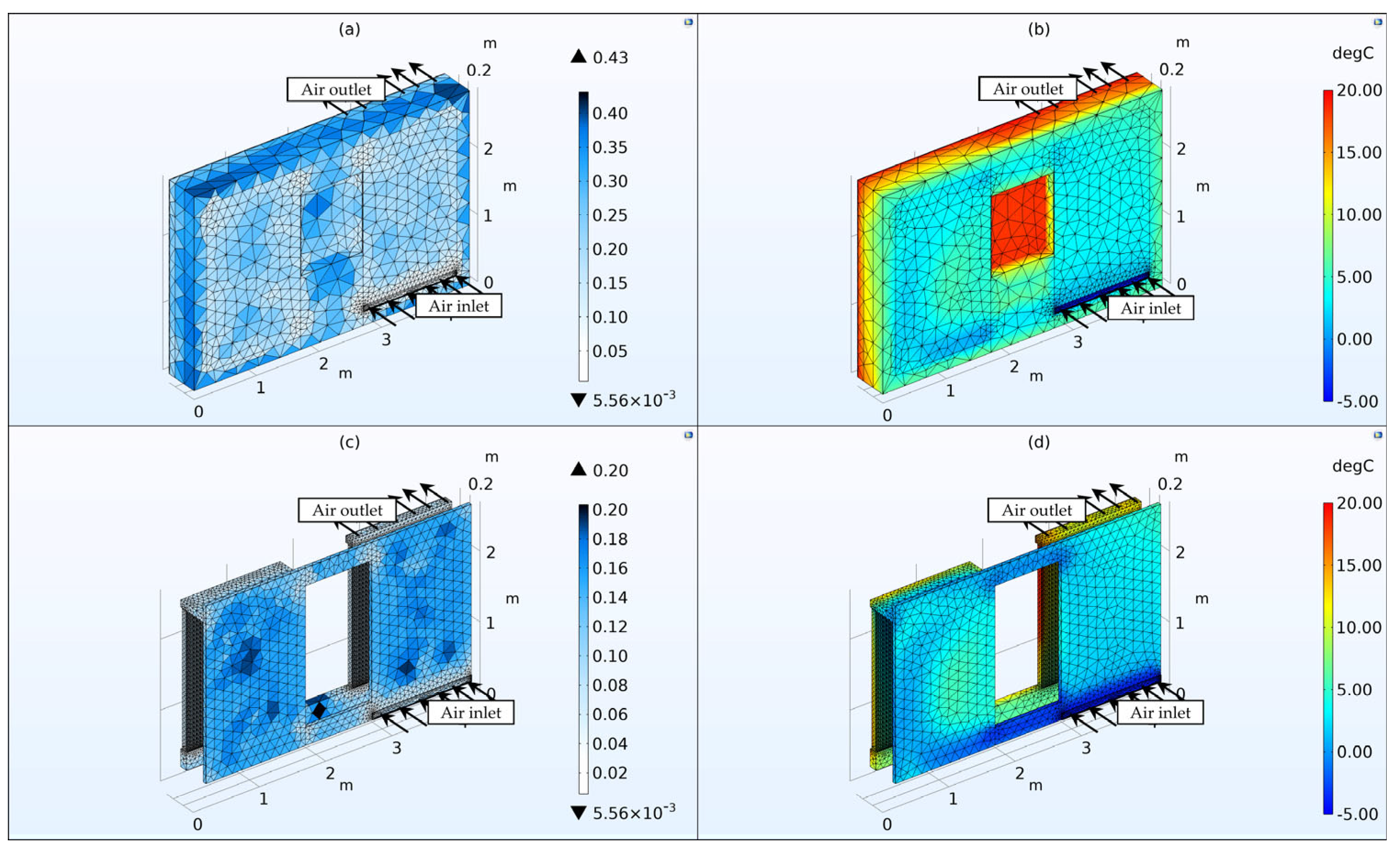
Figure 2 illustrates the numerical mesh used in the numerical simulation, representing the finite element sizes and the overall temperature distribution in both solid and fluid domains. The smallest element size is 5.56 × 10⁻³ m and the largest element size is 0.43 m, considering the mesh that was used. Table 1 presents the main parameters for the materials used in the numerical simulation of the geometrical model.
The finite element numbers according to the types used were 422,840 tetrahedra, 18,338 pyramids, 451,702 prisms, 105,814 triangles, 534 quads, 38,392 edge elements, and 2054 vertex elements. The total number of elements adds up to 892,880. The entire mesh volume is 6.15 m3. The air domain, consisting of all the fluid domains, totaled 595,696 finite elements, mostly prisms, and tetrahedra. The air-domain volume is 0.8253 m3. This represents more than half of the elements for a seventh part of the geometrical model, confirming the increased attention to air circulation and heat transfer.
Table 2 presents the boundary conditions used in the numerical simulation based on the physics module and geometry location. At the surfaces where the domains intersect, continuity boundary conditions for both solid and fluid domains are set automatically by the software. For the surfaces where the fluid and solid domains intersect a wall, a condition was set with no wall slip movement. For all the physics to blend, the Multiphysics modules of non-isothermal flow and heat transfer with surface-to-surface radiation were used to interconnect the three physics modules used in this numerical study for the new proposed design of a Trombe wall.
The interior face of the wall aims to recreate the indoor comfort temperature in the simplest way possible to reduce the computational effort of the simulation and provide reliable results. For this, the temperature of 20 °C was chosen, corresponding to the comfort temperature for 9 out of 12 months. For the summer, the comfort temperature is typically a few degrees higher, but the value was chosen to remain at 20 °C for better comparison of the results as the simulation studied year-long behavior.
Comsol Multiphysics has been extensively utilized in numerous academic and industrial applications, demonstrating its reliability and versatility in capturing complex heat and flow behaviors. In this study, the governing equation for the non-isothermal flow and conjugate heat transfer used in Comsol contains the formulation of both continuity and momentum equations:
where ρ is the density (kg/m3), u is the velocity vector (m/s), p is the pressure (Pa), F is the body force vector (N/m3), and τ is the viscous stress tensor (Pa), which for a compressible fluid is:
where μ is the dynamic viscosity (Pa∙s).
Following up, Comsol Multiphysics solves the heat equation, which for a fluid is given by:
where Cp is the specific heat capacity at constant pressure (J/(kg·K)), T is the absolute temperature (K), q is the heat flux by conduction (W/m2), qr is the heat flux by radiation (W/m2), Q contains additional heat sources other than viscous heating (W/m3), and αp is the coefficient of thermal expansion (1/K):
Also, the physics interface solves the heat transfer for solids with the equation:
where Qted is the thermoelastic damping heat source (W/m3).
For the turbulent flow simulation, the Algebraic yPlus Turbulence model was used in Comsol Multiphysics, which is based on the distance to the nearest wall. It is based on Prandtl’s mixing theory and is suitable for internal compressible flows. The governing equation is based on the Navier–Stokes equations, which in the general form are used by the conjugate heat and flow transfer module and presented at (1) and (2).
For solar radiation, the surface-to-surface radiation module was used in Comsol Multiphysics. The total incoming radiative flux at any point is notated with G, and the total diffuse outgoing radiative flux at any point is notated with J, and called radiosity. The governing equation is:
where eb(T) is the power radiated across all wavelengths and depends on the fourth power of the temperature:
The inward radiative heat flux, q, is given by the difference between the incoming and outgoing radiation:
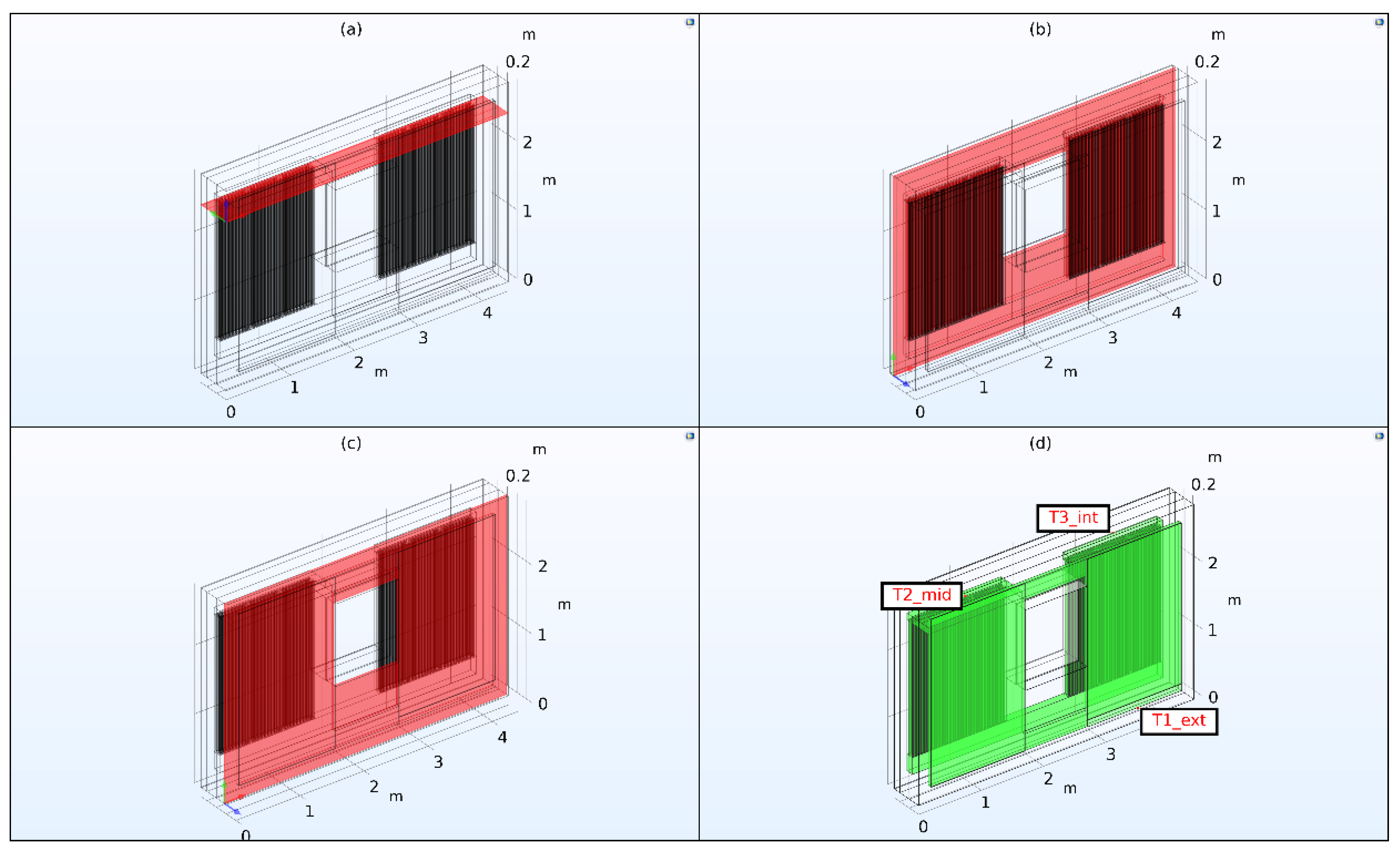
For results interpretation, it is important to study the parts of the system that provide relevant information about the system’s performance. For this, multiple areas were considered. Firstly, the influence of solar radiation on the air cavities must be analyzed. For this, a longitudinal cross-section through the air cavities on the exterior face of the wall was considered. Secondly, the performance of the MPCLBs can be analyzed by studying the conductive and convective heat transfer inside the MPCLBs. A second longitudinal cross-section through the MPCLB wall was considered. Thirdly, the influence of the interior constant temperature of the room influences the MPCLBs’ heat transfer. For analyzing this aspect, a transversal cross-section at the top of the MPCLB wall was considered. In this section, both air entering the MPCLBs from the exterior air cavities and air exiting the MPCLBs and entering the room can be studied.
Finally, the air temperature from the inlet to the outlet provides important information. For this, two-point probes were considered. One is in the air duct between exterior air cavities and MPCLBs, corresponding with the air exiting the air cavities and entering the MPCLBs. The second one is at the air outlet, corresponding with air exiting the MPCLBs and entering the room. Both Figure 3 and Table 3 illustrate and have information about the considered areas of interest where the results will be analyzed and presented in this paper.
For the study, two locations were considered: the cities of Brașov and Constanța. In Romania, based on climate and temperatures, 4 regions are considered from cold to hot. Brașov is located in the coldest region and Constanța is located in the hottest region corresponding to the Romanian climate. Both Brașov and Constanța were chosen based on this criterion and the fact that for these two cities, there are available temperature and solar-radiance data already stored in official government documents. These locations were chosen as minimum and maximum temperatures and solar-radiation conditions for the proposed system. Figure 4 presents the mean monthly temperatures throughout the year for both Brașov and Constanța. Similarly, Figure 5 presents the solar direct and diffuse radiation for both cities of Brașov and Constanța. These values were registered in 2013 in Romania and are available from the Ministry of Development, Public Works, and Administration [23].
The monthly mean solar radiation was chosen after a thoughtful process. Firstly, it was a good way to reduce computational effort for the simulations. Secondly, the available values were processed from hourly mean solar radiation into monthly mean radiation. Therefore, it was observed that the only period in which solar radiance was higher than the highest monthly mean was for about a month in the summer. For all the other periods, the highest hourly solar radiance was lower than the monthly mean. This means that for solar radiation values higher than the monthly ones, results from a hotter month would be the same for 11 out of 12 months of the year. Moreover, using mean monthly solar radiation provided a way to understand the whole year’s behavior of the Trombe wall. The two cities act as the limiting climate conditions for the proposed system. Besides these two simulation cases, solar-radiation availability was considered. For this, for each city’s climate conditions, two cases were considered: with solar radiation (SR) and without solar radiation (SR). Solar radiation is available throughout the year based on geolocation and month. In a time when there is no solar radiation, the system operates without it.
This influences the output of the systems as air temperatures will not increase as much as when solar radiation is considered. For the winter period, most of the day is characterized by having no solar radiation due to the lower number of hours of light and the cloudiness factor. In the summer, no radiation is only a matter of the night hours and can be represented by using shading methods to stop the solar radiation from overheating the supplied air. Table 4 presents more details for the simulated cases in this paper.
3. Results
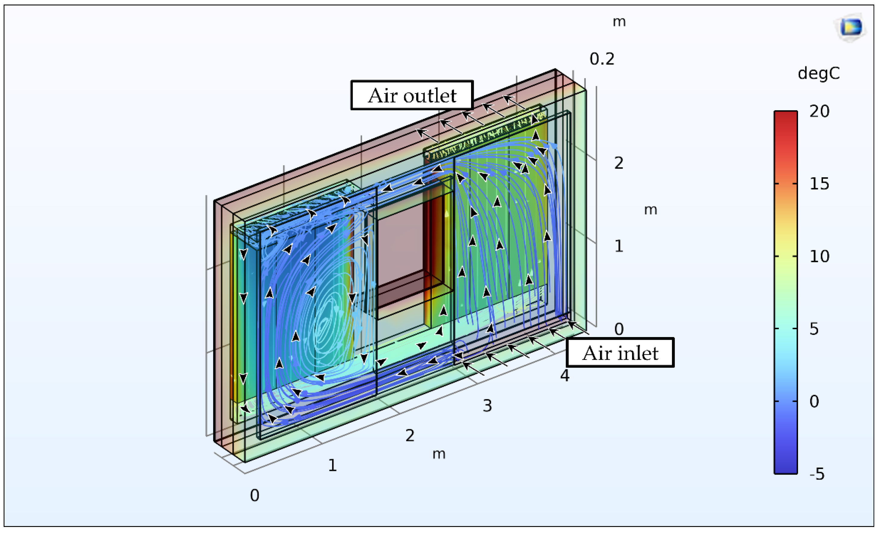
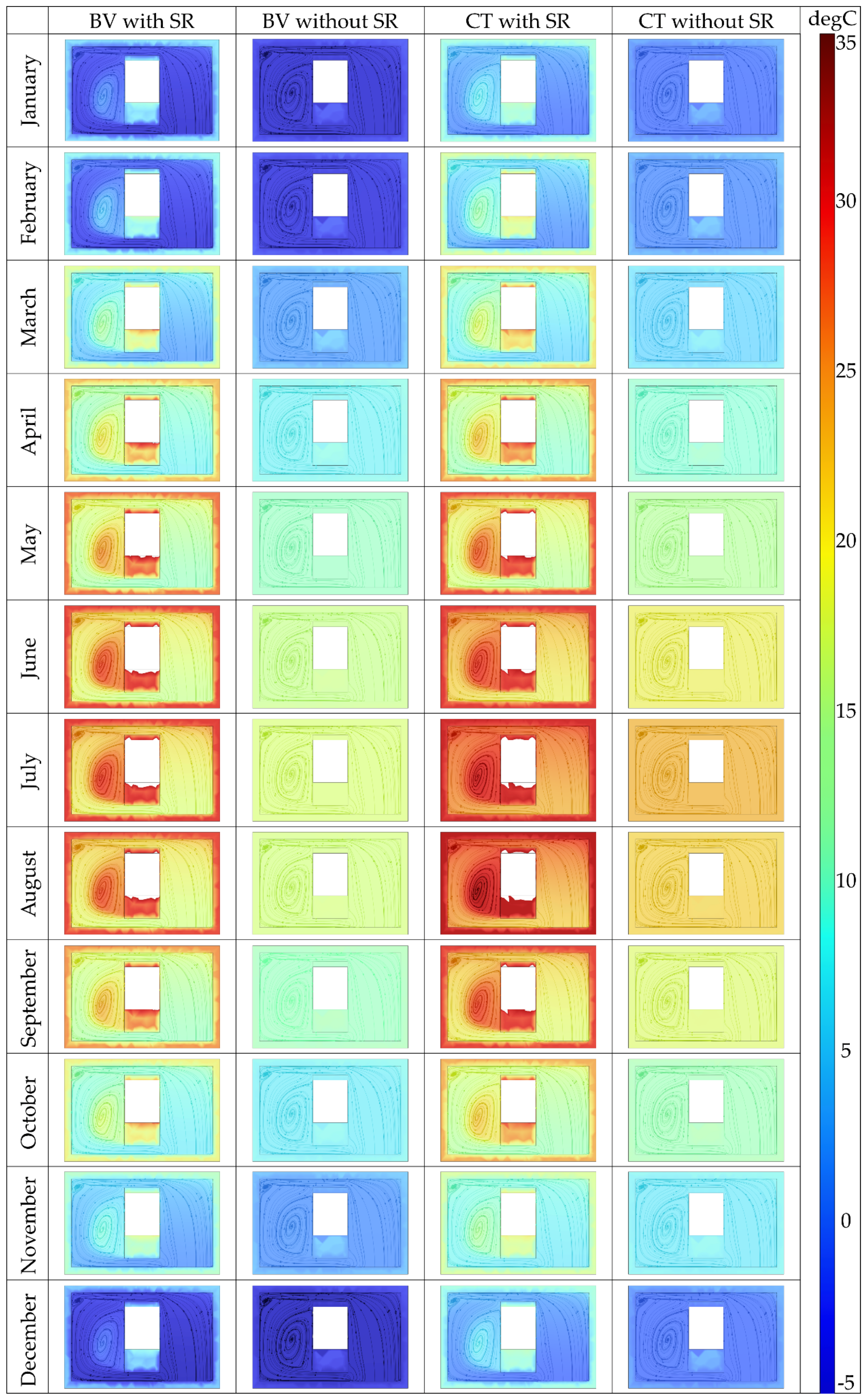
The computational time for the proposed system was approximately 1 h and 45 min. For each of the 4 simulated cases, a stationary simulation was conducted for each month, resulting in a total several 48 simulations. Figure 6, Figure 7, Figure 8 and Figure 9 illustrate the results for the proposed Trombe wall, for a winter month with solar radiation in Brașov for analysis purposes. The results for all the 48 simulations are presented in Figure 10, Figure 11, Figure 12 and Figure 13.
The airflow direction is observed in Figure 6, Figure 7, Figure 8 and Figure 9. Air circulation starts from the exterior through the air-inlet grille on the bottom right of the wall. It enters the air cavity behind the glass from which it circulates through air channels under and above the window into the left air cavity. The left air cavity has an air channel at the top of the wall that connects the exterior air cavities with the interior MPCLB wall. From there, the air circulates downwards through the MPCLBs. At the bottom, it enters another air channel under the window that connects the right side of the wall where it circulates upwards through MPCLBs. Finally, at the top of the wall, corresponding to the top of the room, underneath the ceiling, air enters the room through an air-outlet grille.
Both the fluid domain (air) and solid domains are represented based on a temperature scale. The solid domain is illustrated with transparency, except for the MPCLBs, for a better understanding of the heat transfer. Air circulation from the inlet is visible in the air cavities. Most of the air is circulating to the left side through the air cavity beneath the window. On the right air cavity, the air starts to heat up and heats up even more in the left one. The left MPCLB wall is the first that the air circulates into. This is observed by the fact that the temperature of the MPCLBs on the top-left is lower than the temperature on the right side. Air absorbs thermal energy gradually alongside the path it is circulated on.
Internal air pressure was considered as a study parameter. Multiple simulations were run, varying the pressure in a range of common pressures used for indoor ventilation systems between 50–150 Pa. The results obtained showed low, decimal variations in the temperature fields and for the measured temperature values. Thus, the fan pressure parameter was fixed at 100 Pa.
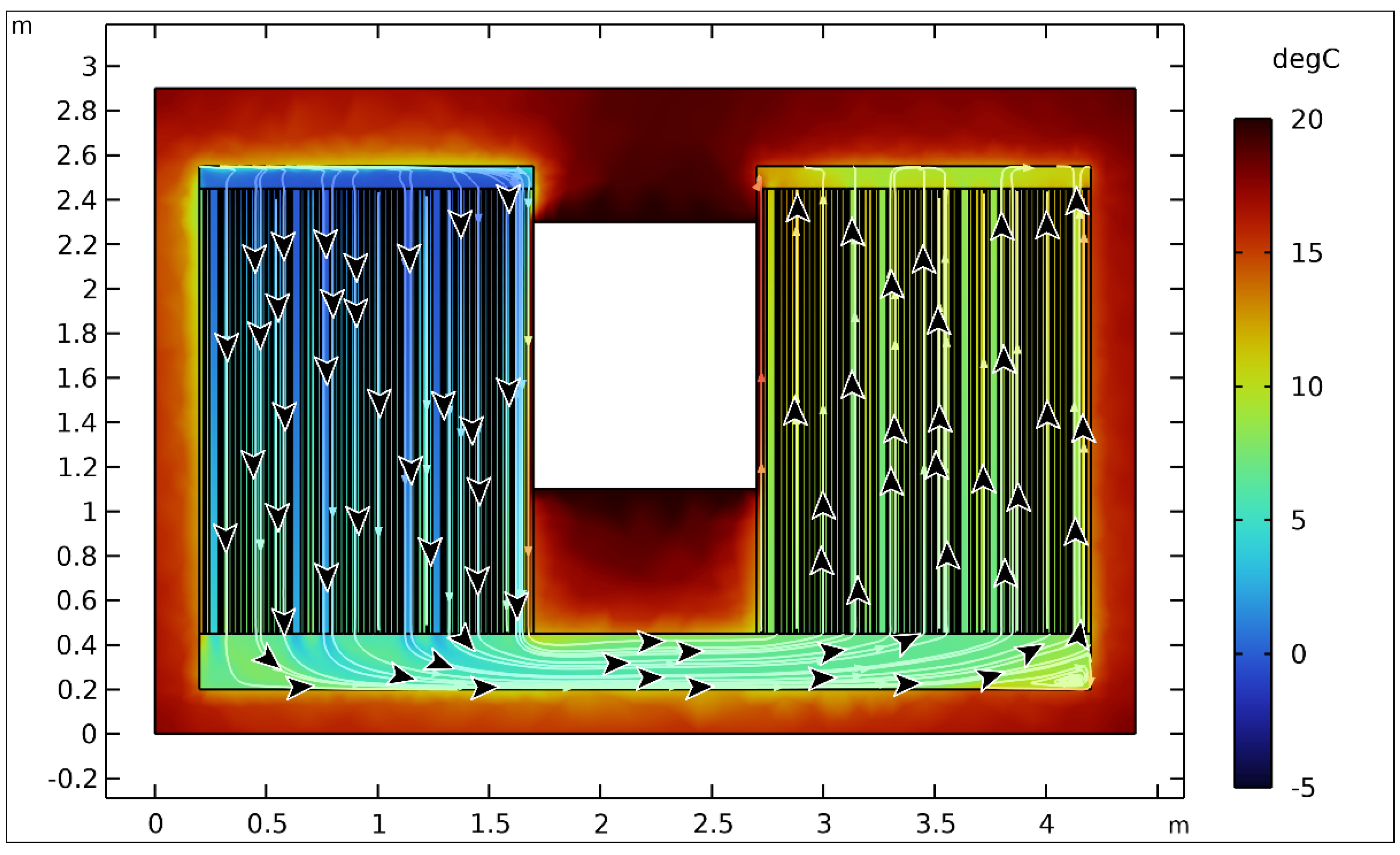
Consequently, Figure 7 illustrates the temperature variation and air circulation on the transversal cross-section above the MPCLB wall. This section is also important for the analysis of the air circulation through the air duct connecting the air cavities and the MPCLBs. It is also observable that the left side has a lower temperature than the right side, being the entering point into the MPCLBs. Temperature increase in the exterior air cavities is lower than the temperature increase happening in the MPCLBs’ air circulation. This is mainly because this figure represents a winter month in Brașov. Furthermore, a constant interior temperature contributes considerably to the air heating, but the interior wall will be subjected to a considerable degree of temperature variation. The high temperature in the middle of the section seen in Figure 7 appears because directly beneath this section is the top of the exterior window.
Following up, Figure 8 illustrates the longitudinal cross-section through the MPCLB wall. The view is seen from the outside, in the exterior of the room. In this section, air’s downward circulation on the left and then upward circulation on the right is visible. Moreover, temperature variation inside the MPCLBs is clearer than in the other section, and in this case, the temperature difference of the air between entering and exiting the MPCLBs is approximately 5–7 °C. Another interesting aspect is that the thermal inertia of the MPCLBs is visible when compared with the air cavity at the bottom of the wall. Air temperature increases more from circulating through the MPCLBs than it increases in the air cavity.
Figure 10 illustrates comparatively the results for all four studied and simulated cases in the tri-dimensional view. Figure 11 illustrates the same but in the transversal cross-section. Consequently, Figure 12 illustrates the longitudinal cross-section through the MPCLBs and Figure 13 illustrates the longitudinal cross-section through the exterior air cavities. In Figure 10, Figure 11, Figure 12 and Figure 13, BV and CT are abbreviations for Brașov and Constanța. In Figure 10 and Figure 13, the solar radiation impact is visible when comparing the cases with and without it. Located on the exterior of the wall, the air cavities serve almost no purpose when there is a lack of solar radiation. The temperature remains almost the same throughout the whole air-circulation path. Comparatively, the cases where solar radiation was considered illustrate an overall increase in air temperature from the solar radiation even in the coldest winter months.
Figure 11 and Figure 12 illustrate the impact that the MPCLBs have on all cases, regardless of the exterior air temperature or solar radiation. Located on the inside of the wall, these bricks benefit from the thermal energy from the room being heated. The temperature increase has the highest value in the winter than in warmer periods or in the summer for both Brașov and Constanța. The best results can be seen during the transitional seasons of spring and autumn, in which air enters the room close to the interior temperature. In Brașov, the periods when this happened are shorter than the period for Constanța, due to its outdoor temperature values, basically from lower exterior temperatures than in Constanța.
4. Discussion
The proposed Trombe wall aims to provide another take on the classic Trombe wall. This study illustrates that using MPCLBs for a Trombe wall, the purpose of which is to be used as a ventilation heat recovery, considerably increases the air temperature. This effect can be seen especially during the winter season. The lower the exterior temperature, the higher the temperature difference that will result. The temperatures from the data probes and the temperature differences for the Brașov and Constanța cases are presented in Table 5 and Table 6. Although the temperature increase is higher when the exterior temperature is lower, during the winter season the air needs to be heated with an auxiliary heat source before entering the room.
In Brașov, from April to October, the results show that the air enters the room having a temperature close to the room temperature, ±2 °C. This period is around seven months, more than half the year. In Constanta, from late March to early June and from September to October, a period of around six months, the air reaches room temperature. Although in the winter, the air entering the room has a temperature higher by approximately 2 °C than in Brașov, in the summer, the air needs to be cooled before entering the room.
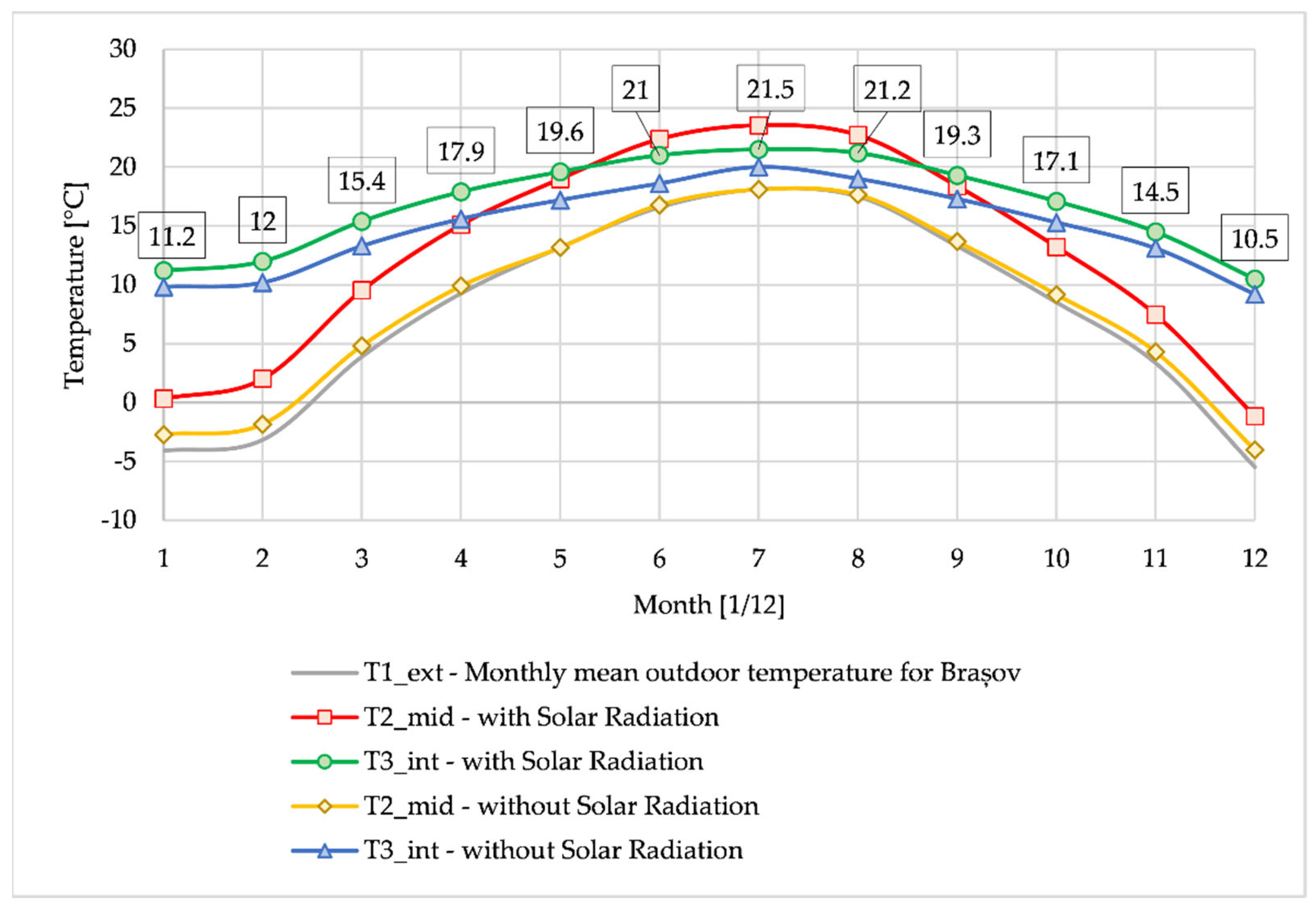
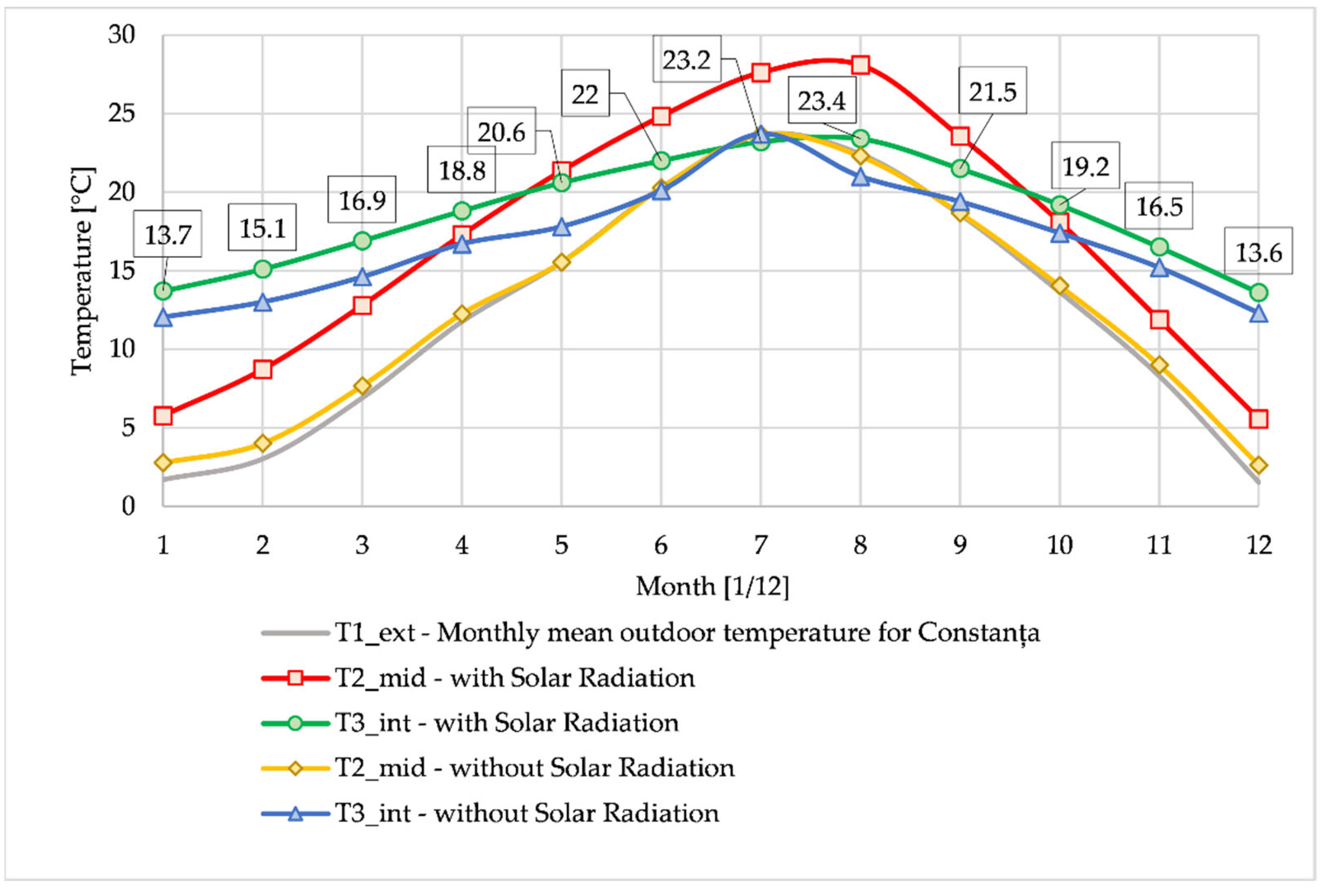
The results presented in Table 5 and Table 6 are illustrated comparatively in Figure 14 for Brașov and Figure 15 for Constanța. In these figures, the impact of the solar radiation is obvious and easy to interpret. In both cities, when no SR was considered, the air temperature in the exterior air cavities had values close to the outdoor temperatures or higher with no more than 1.5 °C, before entering the MPCLBs, meaning the temperature collected from the T2_mid data probe. On the other hand, when SR was considered, the air temperature increased between the exterior (T1_ext) and T2_mid by 4.12–5.83 °C for Brașov and 3.56–5.88 °C for Constanța. This averages to a 4.83 °C increase for Constanța and a 5.13 °C increase for Brașov.
Interestingly, for both cities, between May to September, the air temperature in T2_mid was increased over the interior temperature. This, in turn, created a reversed thermal process in the MPCLBs in this period. The air was cooled when entering the MPCLBs from T2_mid, not heated.
The highest temperature increase occurred inside the MPCLBs. With no solar radiation, the temperature difference varied between 1.35 °C (summer) to 13.24 °C (winter) from T2_mid to T1_int for Brașov. In Constanța, it varied between −1.29 °C (the minus sign meaning cooling in the summer) to 9.69 °C (winter). When SR was considered, the temperature difference varied between −2.04 °C (cooling in the summer) to 11.65 °C (winter) for Brașov. For Constanța, it varied between −4.69 °C (cooling in the summer) to 8.04 °C (winter).
Air velocity is represented in Figure 16. The air-velocity variation was close to zero between all the considered months with low variations due to air temperature and thus, density. In T2_mid, the velocity averaged 0.27 m/s, and when entering the room, the air velocity averaged 0.4 m/s for both cities in all cases.
All the results illustrate the impact that the MPCLBs have on the heat transfer towards the air. Because of the bricks’ thermal inertia, a lot of heat is stored inside the MPCLBs and can be transferred to the air. The low air velocity and the low air flow contribute to the increased heat transfer when the air circulates in this part of the system compared with the passage through the exterior air cavities. Of course, the location of the MPCLBs is very important for avoiding high-temperature variation inside the MPCLBs from the exterior air. This was the main reason why the location of this layer of MPCLBs was chosen to be on the inside of the room. The temperature of the brick would be much more affected by the extreme outdoor temperature variation.
As the results show that for more than half of the year the ventilated air is supplied with temperatures close to the interior air temperature for both cities at the climate limits in Romania, it is evident that for climates intermediary to these conditions, the proposed Trombe wall system will provide better results in the mild temperatures during the winter and summer peaks and longer transitional seasons. A system designed like this should always be integrated properly with the building according to its geolocation, purpose, occupancy, and other important factors. On its own, this system can’t cover the need for an entire year to provide great results for both winter and summer.
The unique contributions and advancements presented by this research are in the potential of using the Trombe wall as a heat recovery system for indoor ventilation, because, in most existing studies, a Trombe wall is used to produce large temperature variations in a building’s envelope material [24], with the purpose to heat or cool the inside spaces. Also, in the literature, part of the energy is mentioned to be transferred into the indoor of the building (the room) through the wall by conduction and partly by natural convection [25,26]. This study proposed forced convection to increase heat transfer.
Of course, the use of a Trombe wall has limitations, and it is known that the real complication of a Trombe wall’s usage is that it can become a source of heat losses during extended overcast days. In this study, this limitation is reduced by using forced convection and automation. The most important limitation of this study is that the system, like any other Trombe wall, is a highly climate-dependent system, meaning location and weather variations could negatively impact the effectiveness of the wall [27,28,29].
5. Conclusions
The system proposed in this study aims to be an alternative way to ventilate residential buildings using the Trombe wall. The results illustrate that the use of MPCLBs as a heat recovery system to heat or cool the air before entering the room is promising. As solar radiation is known to provide considerable amounts of thermal energy from direct and diffuse radiation during the day, interior ambient heat can also be used to heat the air. With the proposed MPCLBs being a part of the Trombe wall used for ventilation, air is heated using interior energy without causing discomfort for the people inside by simply supplying cold or hot air directly inside.
The main conclusions of the numerical study are the following:
- The lower the exterior temperature, the higher the temperature increases when the air enters the room;
- The higher the exterior temperature, the lower the temperature increase when the air enters the room;
- Solar radiation increases the air temperature by an average of 4.5 °C when exiting the air cavity and by an average of 1.8 °C when entering the room;
- With solar radiation considered, the temperature increased between exterior and interior by an average of 6.5 °C for Brașov and 4 °C for Constanța;
- In the summer months, air is heated from the solar radiation to above the interior temperature and the MPCLB wall acts as a cooler for the air. Shading systems should be considered;
- The system can be improved significantly, based on the geolocation of the application. Hotter climates require shades for the summer and colder climates require either more surface for the heat transfer inside the MPCLBs or an auxiliary heat source;
- The proposed systems provided the best results for the transitional seasons, maintaining interior air temperature close to interior temperature for more than half a year.
Further research on this type of system is required, as to the author’s best knowledge, the Trombe wall has not been researched for indoor ventilation systems only; all the existing literature uses the Trombe wall for indoor heating.
An important conclusion is that integrating a renewable energy auxiliary source to heat the air when needed, especially in the winter period, would be a suitable addition to such a Trombe wall system. This can consist of solar thermal panels, photovoltaic panels that store electrical energy, or a residual energy source from inside the building with adequate heat exchangers. For the summer period, the study concludes that a shading system over silica glass is mandatory to stop the air from overheating during the day.
Author Contributions
Conceptualization, A.M.B. and G.N.; methodology, G.D. and N.F.I.; software, A.I.B. and S.I.B.; validation, G.D. and G.N.; formal analysis, M.F.; investigation, A.M.B. and E.C.P.; resources, L.R.; data curation, A.I.B.; writing—original draft preparation, A.M.B.; writing—review and editing, N.F.I. and G.N.; visualization, A.M.B. and S.I.B.; supervision, L.R. and M.F.; project administration, G.N. and A.M.B. All authors have read and agreed to the published version of the manuscript.
Funding
This research received no external funding.
Data Availability Statement
The data presented in this study are available on request from the corresponding author. The data are not publicly available due to privacy issues.
Conflicts of Interest
The authors declare no conflicts of interest.
Nomenclature
| BV | Brașov city in Romania |
| CFD | Computational fluid dynamics |
| CT | Constanța city in Romania |
| HVAC | Heating ventilation and air conditioning |
| MPCLBs | Multi-perforated clay bricks |
| SR | Solar radiation |
References
- Liu, H.; Li, P.; Yu, B.; Zhang, M.; Tan, Q.; Wang, Y.; Zhang, Y. Contrastive Analysis on the Ventilation Performance of a Combined Solar Chimney. Appl. Sci. 2022, 12, 156. [Google Scholar] [CrossRef]
- Briga-Sá, A.; Paiva, A.; Lanzinha, J.C.; Boaventura-Cunha, J.; Fernandes, L. Influence of Air Vents Management on TrombeWall Temperature Fluctuations: An Experimental Analysis under Real Climate Conditions. Energies 2021, 14, 5043. [Google Scholar] [CrossRef]
- Żelazna, A.; Lichołai, L.; Krasoń, J.; Miąsik, P.; Mikušová, D. The Effects of Using a Trombe Wall Modified with a Phase Change Material, from the Perspective of a Building’s Life Cycle. Energies 2023, 16, 7689. [Google Scholar] [CrossRef]
- Singh, H.; O’Brien, P.G. Semi-Transparent Water-Based Trombe Walls for Passive Air and Water Heating. Buildings 2022, 12, 1632. [Google Scholar] [CrossRef]
- Vasileva, I.L.; Nemova, D.V.; Vatin, N.I.; Fediuk, R.S.; Karelina, M.I. Climate-Adaptive Façades with an Air Chamber. Buildings 2022, 12, 366. [Google Scholar] [CrossRef]
- Zhu, Y.; Zhang, T.; Ma, Q.; Fukuda, H. Thermal Performance and Optimizing of Composite Trombe Wall with Temperature-Controlled DC Fan in Winter. Sustainability 2022, 14, 3080. [Google Scholar] [CrossRef]
- Yin, Q.; Liu, H.; Zhou, T. CiteSpace-Based Visualization Analysis on the Trombe Wall in Solar Buildings. Sustainability 2023, 15, 11502. [Google Scholar] [CrossRef]
- Szyszka, J. From Direct Solar Gain to Trombe Wall: An Overview on Past, Present and Future Developments. Energies 2022, 15, 8956. [Google Scholar] [CrossRef]
- Lichołai, L.; Starakiewicz, A.; Krasoń, J.; Miąsik, P. The Influence of Glazing on the Functioning of a Trombe Wall Containing a Phase Change Material. Energies 2021, 14, 5243. [Google Scholar] [CrossRef]
- Taherian, H.; Peters, R.W. Advanced Active and Passive Methods in Residential Energy Efficiency. Energies 2023, 16, 3905. [Google Scholar] [CrossRef]
- Bhadra, S.; Sen, N.; Ak, K.; Singh, H.; O’Brien, P.G. Design and Evaluation of a Water-Based, Semitransparent Photovoltaic Thermal Trombe Wall. Energies 2023, 16, 1618. [Google Scholar] [CrossRef]
- Prozuments, A.; Borodinecs, A.; Bajare, D. Trombe Wall System’s Thermal Energy Output Analysis at a Factory Building. Energies 2023, 16, 1887. [Google Scholar] [CrossRef]
- Sornek, K.; Papis-Frączek, K.; Calise, F.; Cappiello, F.L.; Vicidomini, M. A Review of Experimental and Numerical Analyses of Solar Thermal Walls. Energies 2023, 16, 3102. [Google Scholar] [CrossRef]
- Fidaros, D.; Baxevanou, C.; Markousi, M.; Tsangrassoulis, A. Assessment of Various Trombe Wall Geometries with CFD Study. Sustainability 2022, 14, 4877. [Google Scholar] [CrossRef]
- Năstase, G.; Doboși, I.S.; Brezeanu, A.I.; Taus, D.; Tăbăcaru, M.B.; Vuțoiu, B.G.; Rusu, D.; Bulmez, A.M.; Iordan, N.F. Experimental Heat Transfer, Sound Insulation and Interior Comfort Parameters Assessment on a Box Double-Skin Façade. Buildings 2022, 12, 730. [Google Scholar] [CrossRef]
- Bulmez, A.M.; Ciofoaia, V.; Năstase, G.; Dragomir, G.; Brezeanu, A.I.; Şerban, A. An Experimental Work on the Performance of a Solar-Assisted Ground-Coupled Heat Pump Using a Horizontal Ground Heat Exchanger. Renew Energy 2022, 183, 849–865. [Google Scholar] [CrossRef]
- Bulmez, A.M.; Ciofoaia, V.; Năstase, G.; Dragomir, G.; Brezeanu, A.I.; Iordan, N.F.; Bolocan, S.I.; Fratu, M.; Pleșcan, C.; Cazacu, C.E.; et al. Numerical Investigation on Auxiliary Heat Sources for Horizontal Ground Heat Exchangers. Buildings 2022, 12, 1259. [Google Scholar] [CrossRef]
- Ali, M.H.; Mawlood, M.K.; Jalal, R.E. Minimizing Energy Losses and Enhancing Performance of Trombe Wall Systems through Partial Evacuation of the Air Gap. Energy Build. 2024, 307, 113959. [Google Scholar] [CrossRef]
- Zhou, S.; Razaqpur, A.G. CFD Modeling and Experimental Validation of the Thermal Performance of a Novel Dynamic PCM Trombe Wall: Comparison with the Companion Static Wall with and without PCM. Appl. Energy 2024, 353, 121985. [Google Scholar] [CrossRef]
- Facelli Sanchez, P.; Mercado Hancco, L. Trombe Walls with Porous Medium Insertion and Their Influence on Thermal Comfort in Flats in Cusco, Peru. Energy Built Environ. 2024, 5, 194–210. [Google Scholar] [CrossRef]
- Alsaedi, S.S. Economic Energy Consumption Using Tromb Wall Without Openings by Solar Radiation. Eng. Technol. J. 2011, 29, 374–387. [Google Scholar] [CrossRef]
- Antwan, N.F.; Abdullah, H.K.; Kamali, A.M.M. Reduced the Cooling Load and Improved Insulation Effect on Iraqi Buildings Using the Geothermal Energy Storage Phenomenon. Eng. Technol. J. 2007, 25, 1064–1080. [Google Scholar] [CrossRef]
- Ministerul Dezvoltării Regionale și Administrației Publice (MDRAP). Romanian Ministry of Development and Public Administration. Climate Date for Brașov and Constanța in 2013. Romania 2013. Available online: https://legislatie.just.ro/Public/DetaliiDocumentAfis/191258 (accessed on 28 December 2023).
- Saadatian, O.; Sopian, K.; Lim, C.H.; Asim, N.; Sulaiman, M.Y. Trombe Walls: A Review of Opportunities and Challenges in Research and Development. Renew. Sustain. Energy Rev. 2012, 16, 6340–6351. [Google Scholar] [CrossRef]
- Hu, Z.; He, W.; Ji, J.; Zhang, S. A Review on the Application of Trombe Wall System in Buildings. Renew. Sustain. Energy Rev. 2017, 70, 976–987. [Google Scholar] [CrossRef]
- Elsaid, A.M.; Hashem, F.A.; Mohamed, H.A.; Ahmed, M.S. The Energy Savings Achieved by Various Trombe Solar Wall Enhancement Techniques for Heating and Cooling Applications: A Detailed Review. Sol. Energy Mater. Sol. Cells 2023, 254, 112228. [Google Scholar] [CrossRef]
- Bosu, I.; Mahmoud, H.; Ookawara, S.; Hassan, H. Applied Single and Hybrid Solar Energy Techniques for Building Energy Consumption and Thermal Comfort: A Comprehensive Review. Sol. Energy 2023, 259, 188–228. [Google Scholar] [CrossRef]
- Ruiz-Pardo, Á.; Domínguez, S.Á.; Fernández, J.A.S. Revision of the Trombe Wall Calculation Method Proposed by UNE-EN ISO 13790. Energy Build 2010, 42, 763–773. [Google Scholar] [CrossRef]
- Zeng, Z.Y.; Zhao, B.C.; Wang, R.Z. Passive Day and Night Heating for Zero Energy Buildings with Solar-Based Adsorption Thermal Battery. Cell Rep. Phys. Sci. 2021, 2, 100578. [Google Scholar] [CrossRef]
Figure 1.
The geometrical model for the proposed Trombe wall, highlighting the air-circulation cavities: (a) tri-dimensional view; (b) bi-dimensional side view; (c) bi-dimensional top view.
Figure 1.
The geometrical model for the proposed Trombe wall, highlighting the air-circulation cavities: (a) tri-dimensional view; (b) bi-dimensional side view; (c) bi-dimensional top view.

Figure 2.
The tri-dimensional grid and mesh for the proposed Trombe wall: (a) mesh for solid domains based on element size; (b) mesh for solid domains highlighting temperature variation; (c) mesh for fluid domain based on elements size; (d) mesh for fluid domain highlighting temperature variation.
Figure 2.
The tri-dimensional grid and mesh for the proposed Trombe wall: (a) mesh for solid domains based on element size; (b) mesh for solid domains highlighting temperature variation; (c) mesh for fluid domain based on elements size; (d) mesh for fluid domain highlighting temperature variation.

Figure 3.
Considered sections and measuring points for data acquisition and interpretation: (a) transversal cross-section at the top of the MPCLBs; (b) longitudinal cross-section through the MPCLBs on the interior face of the wall; (c) longitudinal cross-section through the air cavities on the exterior face of the wall; (d) data measuring points for air temperature and velocity.

Figure 4.
Monthly mean outdoor temperature for Brașov and Constanța, registered in 2013 [23].
Figure 4.
Monthly mean outdoor temperature for Brașov and Constanța, registered in 2013 [23].

Figure 5.
Monthly mean direct and diffuse solar radiations for Brașov and Constanța, registered in 2013 [23].
Figure 5.
Monthly mean direct and diffuse solar radiations for Brașov and Constanța, registered in 2013 [23].

Figure 6.
Tri-dimensional view of the proposed Trombe wall, illustrating results for temperature variation.
Figure 6.
Tri-dimensional view of the proposed Trombe wall, illustrating results for temperature variation.

Figure 7.
Transversal cross-section on top of MPCLBs, illustrating results for temperature variation and air circulation.
Figure 7.
Transversal cross-section on top of MPCLBs, illustrating results for temperature variation and air circulation.

Figure 8.
Longitudinal cross-section through the MPCLBs, illustrating results for temperature variation and air circulation.
Figure 8.
Longitudinal cross-section through the MPCLBs, illustrating results for temperature variation and air circulation.

Figure 9.
Longitudinal cross-section through the air cavities, illustrating results for temperature variation and air circulation.
Figure 9.
Longitudinal cross-section through the air cavities, illustrating results for temperature variation and air circulation.

Figure 10.
Tri-dimensional views for all four cases on all months representing temperature variation.
Figure 10.
Tri-dimensional views for all four cases on all months representing temperature variation.

Figure 11.
Cross-sections on top of MPCLBs for all four cases representing temperature variation.

Figure 12.
Cross-sections through MPCLBs for all four cases representing temperature variation.

Figure 13.
Cross-sections through air cavities for all four cases representing temperature variation.
Figure 13.
Cross-sections through air cavities for all four cases representing temperature variation.

Figure 14.
Temperature results in the considered data probe points for Brașov.

Figure 15.
Temperature results in the considered data probe points for Constanța.

Figure 16.
Velocity results in the considered data probe points for Brașov and Constanța.


Table 1.
Numerical model parameters.
| Material | Parameter | Value | Unit |
|---|---|---|---|
| Density | 1.2 | kg/m3 | |
| Air | Thermal conductivity | 0.024 | W/mK |
| Specific heat capacity | 1000 | J/kgK | |
| Density | 2000 | kg/m3 | |
| Brick | Thermal conductivity | 0.5 | W/mK |
| Specific heat capacity | 900 | J/kgK | |
| Density | 2000 | kg/m3 | |
| MPCLBs | Thermal conductivity | 0.5 | W/mK |
| Specific heat capacity | 900 | J/kgK | |
| Density | 2203 | kg/m3 | |
| Silica glass | Thermal conductivity | 1.38 | W/mK |
| Specific heat capacity | 703 | J/kgK | |
| Density | 11.5 | kg/m3 | |
| Expanded polystyrene | Thermal conductivity | 0.05 | W/mK |
| Specific heat capacity | 1450 | J/kgK | |
| Density | 574 | kg/m3 | |
| Gypsum board | Thermal conductivity | 0.2 | W/mK |
| Specific heat capacity | 1100 | J/kgK |
Table 2.
Boundary conditions.
| Physics Module | Location | Boundary Condition Type | Value |
|---|---|---|---|
| Heat transfer in solids and fluids | Exterior face | Temperature | Variable (monthly mean exterior temperature) |
| Interior face | Temperature | 20 [°C] | |
| Exterior face | Heat flux | Variable (external natural convection based on exterior temperature) | |
| Air inlet | Inflow | Variable (heat transfer based on exterior temperature) | |
| Air outlet | Outflow | Variable (heat transfer based on interior temperature) | |
| Wall sides | Thermal insulation | - | |
| Turbulent flow | Air inlet | Fan | 100 [Pa]; 0.025 [m3/s] |
| Air outlet | Grille | Variable (based on inlet) | |
| Surface-to-surface radiation | Exterior face | External radiation | Variable (monthly mean direct solar radiation) |
| Exterior face | Diffuse surface | Variable (monthly mean diffuse solar radiation) |
Table 3.
Details about the considered sections and measuring points.
| Nr. | Type | Location | Details |
|---|---|---|---|
| 1 | Longitudinal cross-section | Exterior air cavities | Air circulation and air temperature variation inside the air cavities at the exterior face of the wall can be observed. |
| 2 | Longitudinal cross-section | Interior MPCLBs | Air circulation, air, and MPCLB temperature variation inside the MPCLBs can be observed. |
| 3 | Transversal cross-section | At the top of MPCLBs | MPCLBs and air temperature variation before and after the MPCLBs can be observed. |
| 4 | T1_ext | Air inlet | Exterior temperature set for simulation corresponding to the monthly mean values. |
| 5 | T2_mid | Air duct between exterior air cavities and MPCLBs | Air temperature after heating from solar radiation and before entering the MPCLBs is collected. |
| 6 | T3_int | Air outlet | Air temperature after circulating through all the proposed systems before entering the room is collected. |
Table 4.
Cases analyzed and simulated.
| Number | City | Solar Radiation |
|---|---|---|
| 1 | Brașov | Yes |
| 2 | Brașov | No |
| 3 | Constanța | Yes |
| 4 | Constanța | No |
Table 5.
Temperature results for Brașov.
| Month | T1_ext | T2_mid with SR | T2_mid without SR | T3_int with SR | T3_int without SR | ∆T(int-ext) with SR | ∆T (int-ext) without SR |
|---|---|---|---|---|---|---|---|
| - | [°C] | [°C] | [°C] | [°C] | [°C] | [°C] | [°C] |
| January | −4.11 | 0.33 | −2.72 | 11.2 | 9.83 | 15.31 | 13.94 |
| February | −3.18 | 2.02 | −1.85 | 12 | 10.2 | 15.18 | 13.38 |
| March | 3.89 | 9.53 | 4.82 | 15.4 | 13.3 | 11.51 | 9.41 |
| April | 9.27 | 15.1 | 9.9 | 17.9 | 15.6 | 8.63 | 6.33 |
| May | 13.17 | 19 | 13.17 | 19.6 | 17.2 | 6.43 | 4.03 |
| June | 16.58 | 22.37 | 16.79 | 21 | 18.6 | 4.42 | 2.02 |
| July | 18.1 | 23.54 | 18.1 | 21.5 | 20 | 3.40 | 1.90 |
| August | 17.5 | 22.71 | 17.65 | 21.2 | 19 | 3.70 | 1.50 |
| September | 13.28 | 18.38 | 13.68 | 19.3 | 17.3 | 6.02 | 4.02 |
| October | 8.5 | 13.22 | 9.17 | 17.1 | 15.3 | 8.60 | 6.80 |
| November | 3.35 | 7.47 | 4.3 | 14.5 | 13.1 | 11.15 | 9.75 |
| December | −5.49 | −1.15 | −4.03 | 10.5 | 9.21 | 15.99 | 14.70 |
Table 6.
Temperature results for Constanța.
| Month | T1_ext | T2_mid with SR | T2_mid without SR | T3_int with SR | T3_int without SR | ∆T(int-ext) with SR | ∆T (int-ext) without SR |
|---|---|---|---|---|---|---|---|
| - | [°C] | [°C] | [°C] | [°C] | [°C] | [°C] | [°C] |
| January | 1.71 | 5.77 | 2.77 | 13.7 | 12.04 | 11.99 | 10.33 |
| February | 3.03 | 8.705 | 4.01 | 15.1 | 13 | 12.07 | 9.97 |
| March | 6.91 | 12.79 | 7.67 | 16.9 | 14.6 | 9.99 | 7.69 |
| April | 11.76 | 17.28 | 12.25 | 18.8 | 16.7 | 7.04 | 4.94 |
| May | 15.54 | 21.35 | 15.54 | 20.6 | 17.8 | 5.06 | 2.26 |
| June | 20.3 | 24.82 | 20.28 | 22 | 20.1 | 1.70 | −0.20 |
| July | 23.66 | 27.61 | 23.66 | 23.2 | 23.7 | −0.46 | 0.04 |
| August | 22.44 | 28.09 | 22.29 | 23.4 | 21 | 0.96 | −1.44 |
| September | 18.59 | 23.55 | 18.67 | 21.5 | 19.4 | 2.91 | 0.81 |
| October | 13.66 | 18.09 | 14.04 | 19.2 | 17.4 | 5.54 | 3.74 |
| November | 8.31 | 11.87 | 8.99 | 16.5 | 15.2 | 8.19 | 6.89 |
| December | 1.54 | 5.56 | 2.61 | 13.6 | 12.3 | 12.06 | 10.76 |
Disclaimer/Publisher’s Note: The statements, opinions and data contained in all publications are solely those of the individual author(s) and contributor(s) and not of MDPI and/or the editor(s). MDPI and/or the editor(s) disclaim responsibility for any injury to people or property resulting from any ideas, methods, instructions or products referred to in the content. |
© 2024 by the authors. Licensee MDPI, Basel, Switzerland. This article is an open access article distributed under the terms and conditions of the Creative Commons Attribution (CC BY) license (https://creativecommons.org/licenses/by/4.0/).
Share and Cite
MDPI and ACS Style
Bulmez, A.M.; Brezeanu, A.I.; Dragomir, G.; Fratu, M.; Iordan, N.F.; Bolocan, S.I.; Rozorea, L.; Popa, E.C.; Năstase, G. CFD Analysis for a New Trombe Wall Concept. Buildings 2024, 14, 579. https://doi.org/10.3390/buildings14030579
AMA Style
Bulmez AM, Brezeanu AI, Dragomir G, Fratu M, Iordan NF, Bolocan SI, Rozorea L, Popa EC, Năstase G. CFD Analysis for a New Trombe Wall Concept. Buildings. 2024; 14(3):579. https://doi.org/10.3390/buildings14030579
Chicago/Turabian StyleBulmez, Alexandru Mihai, Alin Ionuț Brezeanu, George Dragomir, Mariana Fratu, Nicolae Fani Iordan, Sorin Ionuț Bolocan, Lucian Rozorea, Eugen Călin Popa, and Gabriel Năstase. 2024. "CFD Analysis for a New Trombe Wall Concept" Buildings 14, no. 3: 579. https://doi.org/10.3390/buildings14030579
Note that from the first issue of 2016, this journal uses article numbers instead of page numbers. See further details here.