
Experimental Research on the Floating Amount of Shield Tunnel Based on the Innovative Cumulative Floating Amount Calculation Method
1
School of Civil Engineering Architecture and the Environment, Hubei University of Technology, Wuhan 430068, China
2
Engineering and Technology College, Hubei University of Technology, Wuhan 430068, China
*
Author to whom correspondence should be addressed.
Buildings 2024, 14(5), 1228; https://doi.org/10.3390/buildings14051228
Submission received: 19 March 2024
/
Revised: 20 April 2024
/
Accepted: 23 April 2024
/
Published: 25 April 2024
(This article belongs to the Section Building Structures)
Abstract
:The study of shield tunnel segment flotation is crucial for controlling the precision of underground excavation projects. Based on Winkler’s beam foundation theory, the load structure method, and the equivalent continuous beam model, and by considering the mechanical and spatial conditions that cause segment flotation, a novel theoretical calculation method for cumulative flotation is proposed using a simplified equivalent stiffness model of the tunnel. Additionally, a new concept of “equivalent flotation force” is introduced. The rationality and applicability of this theoretical calculation method are verified by comparing it with on-site construction data from the Yuanjiang River Crossing Tunnel Project in Changde, Hunan Province, China. The experimental results demonstrate that the theoretical calculation closely approximates the surface deformation monitoring data of the tunnel alignment in the eastern section of the project, and their deformation patterns are similar. Near the starting shaft, there is significant settlement influenced by stratum loss due to smaller tunnel flotation, with greater settlement occurring in the upper part. However, at approximately 45 m into both sections, they enter a deformation stability zone showing significant correlation in longitudinal deformation. Through comparison and verification of on-site experiments and theoretical model analysis, we preliminarily elucidate the feasibility of this innovative cumulative flotation theoretical calculation method which provides an important theoretical basis for assessing segment flotation issues in subsequent tunnel shield construction evaluations.
1. Introduction
The shield tunnel uplift problem in the past has not been highlighted, and shield machine diameter is small. Because the uplift force is limited, not enough to lift the tunnel tube produced by the uplift, individual projects appearing in the tube sheet upward displacement problem is caused by the shield machine in the process of advancing the angle of control with the design axis deviations. However, with the increasing diameter of the shield machine, the uplift force has become a non-negligible part in the shield tunnel force analysis, and many problems such as tube sheet breakage in many projects are mostly related to it [1,2,3].
At present, scholars have gradually formed a consensus on the reasons for the generation of tunnel uplift [4,5,6], i.e., the reasons for the generation of uplift of the tube sheet can be roughly divided into mechanical conditions and spatial conditions in two parts. The mechanical conditions include the following. (1) The slurry wrapping the tube sheet has a greater density compared to water when it is not solidified, so it will produce a larger buoyancy force on the tunnel [7,8,9] (referred to as the static buoyancy force in this paper), and the slurry with a long initial coagulation time will undoubtedly produce a longer period of buoyancy effect on the tube sheet. In the faster stage of shield tunneling, the early coagulation of the slurry wrapped by the tunnel segment is longer, which will also affect the newly detached from the shield. This will also adversely affect the uplift of the tunnel section newly detached from the shield tail. (2) Concentrated localized uplift forces (referred to in this paper as dynamic uplift forces) exist on the pipe sheet due to the instability of the slurry flow [10], especially when the pressure-tight grouting method is used so that the slurry collects below the pipe sheet. (3) When the tunnel is adjusted in direction, the eccentric thrust provided by the jacks makes the compressive stress under the tube sheet larger than that above, and the tube sheet will have upward bending deformation. (4) Poor control of the water pressure in the cut at the palm face of the mud–water shield excavation results in the phenomenon of “knocking the head” of the shield, and the shield tail is lifted to cause upward displacement of the tube sheet. (5) The disturbance of the soil body by the surrounding construction projects causes the tunnel to be subjected to vertical upward force, such as unloading from the excavation of the foundation pit above it, and so on. All these situations can trigger the shield tunnel machine. All these situations can cause the tube sheet to float upward during the shield machine’s tunnel boring operation.
More and more scholars have been studying the uplift phenomenon of tunnel tubes after detaching from the shield tail, which is common in engineering. In the study of analyzing the reasons for tunnel uplift, Shen [11] proposed uplift control measures and remedial methods for the intrinsic reasons and extrinsic conditions for tunnel tube uplift from the analysis of geological conditions, shield attitude control, grouting outside the lining, and other aspects. Ye et al. [12] systematically analyzed the reasons leading to the uplift of the tunnel, summarized the effects of grouting, foundation rebound, building clearance, etc., on the uplift of the tunnel, and explored the theoretical aspects of anti-floating calculations of shield tunnels of very large cross-section. Wei et al. [13], based on the Euler–Bernoulli beam theory, established the uplift longitudinal analysis to improve the model to analyze the uplift force during the construction week, and obtained the change of the influence of the depth of burial on its uplift force, which is an important basis for the subsequent construction to assess the size of the uplift force. Chen et al. [14] used the XGBoost algorithm to calculate the uplift of tunnel tube sheet and compared the experimental results with the particle swarm optimization–random forest (PSO–RF) algorithm of Ye et al. [15], which verified the reliability of the algorithm, and it has an important reference significance for the guidance of the subsequent practical engineering. Ye et al. [16] attributed the main reason for the uplift of the tunnel to the role of the “dynamic uplift force” and analyzed the force mechanism to obtain the formula for calculating the grouting pressure in the most unfavorable state. Ye et al. [17] proposed to summarize the reasons for the uplift of shield tunnel tubes into “static uplift force” and “dynamic uplift force”, accordingly proposed an anti-floating calculation model, and analyzed the influence mechanism of grouting operation on the uplift of the tunnel. Ye et al. [18] analyzed the effect of the role of the tube sheet and tube sheet on the surrounding rock on the uplift of the tunnel. Pi [19] comprehensively analyzed the substantive reasons for tube sheet uplift, combined with the longitudinal stiffness, the length of the unconsolidated section of the grouting slurry, the nature of the stratum, and other control measures proposed for tube sheet uplift. Ye et al. [20] analyzed the influence of jack thrust, grouting pressure, uplift force, shield shell force, assembling load, and other loads on tunnel uplift, and proposed that in order to ensure the safety of the tunnel construction period, the special characteristics of the construction process should be specifically considered in the design of the shield tunnel, and targeted design. As for the theoretical modeling analysis method, Jiang et al. [21] introduced the design development history of shield machinery in the past decades and proposed that for a soft soil shield tunnel, dividing it into horizontal and vertical for solving separately is an effective theoretical simplification analysis method. Jing [22] deepened the equivalent continuumized beam model, proposed the calculation method for longitudinal equivalent tensile and compressive stiffnesses and bending stiffness of the shield tunnel, and verified its reasonableness for the longitudinal analysis of the tunnel. Based on two-sided elastic foundation beam theory, and by modifying longitudinal equivalent continuity model and slurry annular filling theory, Zhang et al. [23] further analyzed the superposition effect of shield construction and the influence law of slurry pressure distribution on tube sheet uplift based on the consideration of uplift force deformation. Yang et al. [24] established a theoretical calculation model of uplift based on the force state of pipe sheet and verified the reliability of the model by comparing the shield interval project from the No. 3 air shaft to Caoqiao Station of the Beijing Metro New Airport Line.
From the perspective of theoretical analysis, the above scholars focus on the study of tunnel response mode and deformation law under the action of uplift force, applying models such as Winkler foundation beam to analyze the uplift problem of the tunnel, and obtaining some formulas for calculation of tunnel force, uplift, equivalent stiffness calculation, etc., and some of the obtained results have the conditions of being applied to actual engineering projects. In the tunnel cross-section tube sheet deformation research, scholars mostly study the tunnel through the simplified plane strain problem by using the construction of the “beam-joints” and other models, from the two-dimensional point of view to analyze the tube sheet force situation. However the shield tunnel in the construction process does not fully comply with the plane strain problem assumptions, the actual tube sheet force in the axial axis of the tunnel, the actual stress on the axial axis of the tube sheet, and the actual stress on the axial axis of the tunnel. However, during the construction of a shield tunnel, the assumption of the plane strain problem is not fully complied with, and the actual force of tube sheet in the axial direction is also drastically changed. Therefore, the equivalent of two-dimensional plane research does not reflect the real force situation of the tunnel tube sheet. In the study of longitudinal uplift deformation of tunnels, the equivalent stiffness beam method has been greatly promoted, which can fit the maximum uplift deformation of the tunnel in the normal advancement section of the shield, but few scholars have researched the overall deformation of tunnels, especially in the conditions of short tunnel length of the starting section, and the depth of overburden is shallow and seepage is complicated near the starting shaft. Especially in the shield construction of a cross-river tunnel, the tube sheet uplift phenomenon is very common, mainly due to the cross-river tunnel and the general stratigraphic environment of the tunnel compared to the environment in which it is located with a high water table, seepage, water pressure fluctuations with precipitation, and other characteristics. In the process of tunnel excavation, the original water and soil body were replaced with a hollow tubular tunnel, so that the surrounding liquids, fluid-plasticized water, and soil body act on the tunnel to produce a greater-than-its-own weight of the uplift force. The over-excavation of the shield and the compressibility of the shallow overburden provide conditions for the uplift of the tunnel. All these problems bring uncertainties to the uplift deformation of the tunnel.
The current study mostly focuses on the instantaneous uplift of the tunnel generated by the unconsolidated grouting pressure but does not consider the cumulative uplift of the tube sheet during the whole construction period, which cannot fully reflect the overall uplift characteristics of the tube sheet. In view of the above problems, this study will discuss the tunnel from two levels of transverse single-ring tube sheet and longitudinal equivalent stiffness beam based on the load–structure design method of the tunnel and combined with the practical application of the project, and comprehensively consider the factors affecting the uplift of the tube sheet. By analyzing the force characteristics of the tube sheet during the construction period and using the tunnel equivalent stiffening model [25], the theoretical calculation method of the cumulative uplift of the tube sheet is proposed in order to understand the uplift phenomenon of the tube sheet more comprehensively.
2. Analysis of Uplift Theory Based on Tunnel Structure Design
By incorporating the equivalent stiffness model into the tunnel simulation calculation, this study aims to analyze and investigate the uplift problem, bending deformation, compression deformation of the tunnel, tube sheet pressure, tensile and bending deformations of longitudinal connecting bolts, as well as forces acting on bolts and tube sheets. Additionally, it examines the overall ring tube sheet force across cross-sections and analyzes uplift situations along the axial direction in longitudinal sections.
2.1. Force Analysis of the Whole Ring Tube Sheet in Cross-Section
Firstly, the mode of action of each force is analyzed separately by examining a single ring of tube sheet in the tunnel (i.e., transverse single-ring tube sheet of the tunnel). Based on the actual conditions in tunnel construction and utilizing the load–structure method, we propose the following assumptions:
- (1)
- The tube sheet ring is analyzed as a whole and simplified to a planar problem in the cross-section analysis stage, disregarding the influence of longitudinal forces (such as shield machine top thrust) on the ring sheet.
- (2)
- Neglecting the horizontal force and displacement of the tunnel, as well as disregarding the reaction force exerted by the strata in the horizontal direction, this study exclusively focuses on investigating vertical uplift of tunnels.
- (3)
- By disregarding the uplift acceleration of the tube sheet, the model is examined as a force equilibrium system.
The tube sheet during the construction period is mainly affected by six factors: static uplift force, dynamic uplift force, gravity, friction between rings, shear force of bolts between rings, and ground reaction force (Figure 1), based on the aforementioned three assumption conditions and analysis of the uplift force.
The horizontal ground reaction force in the tunnel is disregarded, thus only the upper and lower ground springs are employed in Figure 1 to represent the vertical restraining effect of the ground on the tube sheet ring.
From the assumption of an equilibrium force system combined with theoretical mechanics analysis:
where
- —Upward buoyancy force on the tunnel;
- —Tube sheet gravity;
- —Bolt shear resistance;
- —Friction between tube sheet rings;
- —Foundation reaction force;
- —Static uplift;
- —Dynamic uplift.
- (1)
- Uplift force
Based on the force analysis of the tunnel tube sheet in Figure 1, the uplift force is divided into static uplift force and dynamic uplift force to be calculated separately.
The static uplift force is determined using Archimedes’ principle.
where
- —Outer radius of the tunnel segment;
- —Fluid heavy in wrapping the tunnel.
The dynamic uplift force has considerable randomness due to the uncertainty of the construction and the penetration and movement of the grout slurry in the soil body. Ye [26] analyzed the dynamic buoyancy force in detail based on Maag column diffusion theory and spherical diffusion theory. In this section, we consider the most unfavorable situation that the slurry is concentrated at the bottom of the ring sheet under the pressure-tight grouting method (as shown by the dynamic uplift force at the bottom of the ring sheet in Figure 1), at which time the dynamic uplift force is
where
- —The angle between the boundary of the grout distribution area and the vertical direction, and in the most unfavorable case = 45°;
- —Angle with the x-axis;
- —Grouting pressure.
- (2)
- Conduct oneself with dignit G
The self-weight per unit length of the tube sheet is
where
- —Inner diameter of tube sheet;
- —Tube sheet heavy.
- (3)
- Friction between tube sheet rings ,
The friction force between the annular seam surface of the single-ring pipe sheet and the single-ring pipe sheet, which acts as an anti-buoyancy effect, is:
where
- —Number of connecting bolts between tube sheet rings;
- —Friction coefficient between tube sheet rings;
- —Preloading of individual inter-ring connecting bolts;
- —Residual pressure of the thrust of the shield jack located on the j-ring segment.
- (4)
- Bolt shear resistance
As the thickness of the lining is much smaller than the average radius of its ring, the pipe sheet ring can be approximated as a thin-walled circular cross-section, the pipe sheet is subjected to a uniform distribution of shear stress along the wall thickness, and then the maximum shear stress is calculated as follows:
where
- —Shear force on the tube sheet ring under the action of the upper buoyancy force;
- —Thickness of tube sheet;
- —Average radius of tube sheet ring direction;
- —Allowable shear strength of bolts.
The floating calculation should only consider the self-weight of the tube sheet, ensuring that no misalignment occurs. However, to allow for a certain amount of misalignment deformation without subjecting the bolts to shear stress, both the self-weight of the tube sheet and the resistance at the ring seam should be taken into account. Additionally, in order to incorporate larger inter-ring misalignment deformation, the calculation should include factors such as the self-weight of the tube sheet, inter-ring resistance, and bolt flotation.
In the tunnel uplift process, the misalignment between the tube sheet ring and ring is often very small, reflecting the characteristics of the local multi-tube sheet common uplift. At this time, the resistance and bolt shear are not fully reflected, so this paper considers the most unfavorable situation but does not take into account the resistance and bolt shear of the anti-floating role of the resistance.
- (5)
- Formation reaction force
In the load–structure method, the ground reaction force is calculated based on the Winkler foundation beam theory, and its magnitude depends on the ground reaction coefficient and the width and vertical displacements of the structure, among others. According to the Winkler elastic foundation beam, it is known [27] that under the action of only uniform load (x), the beam end and the corresponding foundation displacement (x) satisfy the differential equation below:
where
- —Formation reverse force coefficient;
- b—Beam width, take the outer diameter of the tube sheet;
- —Bending stiffness of beam section (i = 1, 2, 3).
Equations (2)–(9) are a fourth-order constant coefficient linear non-chi-square differential equation when (x) = ai0 + ai1 x1 + ai2 x2 + ai3 x3 ( is an arbitrary constant, j = 1, 2, 3, 4). The general solution of this equation is
In summary, based on the force analysis of the whole ring of tubes in the tunnel cross-section, the role of each vertical force on the tunnel is clarified and finally simplified to three main forces, namely uplift, gravity, and ground reaction force, to carry out the next study.
2.2. Analysis of Uplift in the Axial Direction of the Longitudinal Section
A tunnel is a long underground structure, and only analyzing a ring of tube sheet is not able to fully describe the uplift characteristics of the whole tunnel. The transverse tunnel is a ring structure, mechanically more stable, because the wraps around the tube sheet are pointing to the center of the circle, which makes a ring of the tube sheet within the mutual extrusion, in the case that the tube sheet itself does not destroy the wrap, so as to enhance the stability of the ring of tube sheet and to avoid tension damage within the tube sheet. The transverse joints in the ring are avoided from tensile damage.
Unlike the excellent structural shape and high stress performance of the transverse tube sheet ring, the longitudinal characteristics of the longitudinal tunnel are very sensitive to the response to unbalanced forces, especially at the bolts between the tube sheet rings, which are very prone to tensile and shear damage at the bends. The longitudinal environment of the tunnel is constantly changing with the excavation, and the depth of overburden, and the nature of the surrounding rock and the water pressure tend to change greatly with the excavation, which makes the longitudinal stress conditions of the tunnel unstable and improves the stability of the tunnel. This makes the tunnel longitudinal stress conditions unstable and raises the difficulty of quality control (e.g., flatness, etc.) of the longitudinal tunnel works, thus aggravating the risk of damage to the tube sheet itself and the inter-ring bolts, which will have a negative impact on the commissioning of the tunnel at a later stage.
In the longitudinal direction, tunnels are formed by alternating tube sheets and inter-ring bolts. Based on this, the multi-hinge ring method and the beam–spring model in the load–structure method attempt to fully reflect the longitudinal characteristics of tunnels, so they are simulated separately and the corresponding physical and mechanical properties of the tube sheets and bolts are given to carry out the corresponding research. This method is a complete representation of the longitudinal characteristics of tunnels, which is in line with the actual engineering situation. However, on the one hand, the large number of bolts and joints makes the calculation difficult and cumbersome, and on the other hand, different tunnels adopt different tube sheet splices and bolt arrangements, which makes it difficult to accurately represent the load-bearing capacity of different types of “tube sheet-bolt” structures. On the other hand, different tunnels adopt different splices and bolt arrangements, which makes it difficult for this method to accurately reflect the load-bearing methods of different types of “tube-bolt” structures, and it cannot fully fit the characteristics of specific projects, thus resulting in fitting errors.
As shown in Figure 2, in the study of longitudinal deformation performance of tunnels, scholars primarily focus on the overall tensile, compressive, bending, and shear phenomena within the tunnel. Investigating specific bolts or rings in tube sheets is deemed unnecessary as it reduces calculation and simulation efficiency due to an excessively detailed equivalence model.
The modified inertia method is based on the consideration of ensuring equivalent longitudinal stiffness in the tunnel. In this approach, a section of the tunnel is treated as a complete unit to calculate its actual longitudinal deformation, while disregarding complex simulations involving bolts and joints in inter-tube sheets or rings. By improving how effectively bending stiffness and bending moments are reflected by these bolts and joints during tunnel bending deformations, calculations become simpler yet more accurate.
In the study of tunnel uplift problem, shear deformation is rarely observed in tunnels (it is more commonly observed in surrounding rock faults or adjacent cross-project conditions). Regarding compression deformation, only the tube sheet undergoes compression. At this stage, the longitudinal connecting bolts do not play a role and can be directly considered based on the tube sheet. In tension and bending deformations, both bolts and connections to the tube sheet experience equal forces—tensile stress for tension and compressive stress for bending on one side of the neutral axis, while tensile stress occurs on the other side. This characteristic ensures consistency between tunnels and equivalent beams in terms of macroscopic force and deformation characteristics, thereby rationalizing the equivalence process.
As shown in Figure 3, the primary manifestation of the tunnel uplift problem lies in the occurrence of vertical non-uniform uplift deformation between tube sheets. Therefore, this paper focuses on investigating the concept of “equivalent bending stiffness” within the framework of an equivalent stiffness model.
The calculation unit for determining the relative angle of rotation, or curvature due to bending, between the planes of adjacent tubular rings at the ring–seam joint is defined as the segment between their centerlines (Figure 4). When both sides of this unit experience bending moments, a curvature is generated. To establish the relationship between bending moment and corner, certain assumptions are made for the shield tunnel.
Set 4 basic assumptions as shown in Figure 4.
(1) The underlying assumption is that the magnitude of deformation at each point within the cross-section is directly proportional to its perpendicular distance from the neutral axis.
(2) The assumption is made that the position of the neutral axis remains constant along the axial direction of the tunnel, and there is a consistent stress distribution in the annular cross-section of the tube sheet.
(3) The bending moment M is such that the tube sheet bears the pressure on the calculation unit, while the bolt carries the tension, both of which are constrained by the neutral axis.
(4) The distribution of the bolts in the calculation unit is assumed to be continuous for the purpose of facilitating calculations.
According to the coordination conditions of longitudinal deformation at the location of the ring joint, it can be obtained that
where
- —Interface corner;
- —Two sections of tube sheet upper length;
- —Inner diameter of tube sheet;
- —Outer diameter of tube sheet;
- —Vertical distance from the centerline of the tube sheet to the uppermost part of the range of deformation curves of the lower tube sheet;
- —Strain in the upper part of the deformation range of the bolt;
- —Deformation of bolts after stress.
From the longitudinal force equilibrium condition at the ring joint, we have:
where
- —Strain in the lower part of the deformation range of the bolt;
- —Curvature of tube sheet bending;
- —Coefficient of deformation;
- —Modulus of elasticity of deformation line.
The position of the neutral axis can be obtained from Equations (14) and (15):
From the bending moment equilibrium condition
From Equations (14) and (17), we can obtain the interface angle of rotation
where
- —Bending moment.
From the equivalent stiffness continuous beam model, the angle of rotation corresponding to it after the bending moment is obtained:
The equivalent elastic bending stiffness of the tunnel can be obtained from Equation (19) as
where
- —Moment of inertia;
- —Tube sheet bending stiffness;
- —Equivalent elastic bending stiffness.
The focus of this section lies in the equivalent stiffness model for tunnel simulation calculations, particularly when addressing tunnel uplift problems and bending deformations. This model simplifies the intricate simulation of bolts and connections, enhancing computational efficiency by equating the longitudinal tunnel stiffness. The equivalence process is based on ensuring consistency between the tunnel and the equivalent beam in terms of macroscopic force and deformation characteristics. This guarantees accuracy and simplicity in calculation while establishing a theoretical foundation for introducing the longitudinal equivalent stiffness calculation model for uplift volume.
3. Longitudinal Equivalent Stiffness Calculation Model for Uplift Volume
The tunnel longitudinal analysis model based on the elastic foundation beam theory was established by Wang [28], as depicted in Figure 5. To account for the solidification process of grouting slurry at the shield’s end, the longitudinal direction of the shield tunnel is divided into three segments: (beam segment ① ② ③) from node 0 to 3, each with its own stiffness (i = 1, 2, 3), and corresponding foundation bed coefficients (i =1, 2, 3). Beam section ① (0~x1) considers the constraint effect of the shield tail on the tube sheet after assembly completion (typically comprising about 2–4 rings within the shield shell), allowing for a chain bar constraint to be set at position zero. Meanwhile, this beam section is situated in the shield tail, and the influence of the foundation on the deformation of the tube sheet cannot be accounted for. To ensure a consistent derivation of the formula, a small value of k1 is employed as the bed coefficient for beam section ①, and beam section ② (x1~x2) represents the area affected by grouting slurry. Considering its time-varying nature, we assume that uplift force acts on beam section ② in a triangular distribution pattern. However, in reality, as the slurry hardens over time, there should be a linear increase in the actual bed coefficient. For simplicity in this paper’s derivation process, an average value for k2 within the range of x1 to x2 is adopted, beam section ③ (x2~x3) assumes this same average bed coefficient from beam section ②, and finally, beam segment ④ (x3~x4) exhibits a linear relationship with regards to its bed coefficient. Beam segment ④ (x3~x4), being far away from the shield tail section where slurry has already condensed and hardened significantly due to minimal constraint from shield tail forces, can be considered as a free end. The lengths of individual beam segments can be selected based on characteristics such as slurry properties and stratum conditions where shield tubes are located. Additionally, it is assumed that: (1) lateral deformation of tunnel lining is negligible, and (2) structural deformations adhere to flat-section assumptions.
As shown in Figure 5, there is no uniform load on the beam end ① ③, so its Winkler elastic foundation beam foundation displacement equation is generalized as
Beam end ② considers triangular homogeneous loads , yielding available Equation (22):
The co-ordination equations for satisfying the deformation, corner, shear, and bending moments between the segments of elastic foundation beams are
where is the deformation at the ith section of the beam, j node (i is the beam unit number, j is the beam node number, i = j = 1, 2), and is the equivalent stiffness of each section of pipe sheet. Node 0 and node 3 should satisfy the boundary conditions.
The quadratic equations system, concerning the constants ci1, ci2, ci3, and ci4 (where i = 1, 2, or 3), can be solved by differentiating Equations (21) and (22) up to third order. Subsequently, these derivatives should be substituted into the coordination equations and boundary conditions.
The aforementioned tunnel anti-floating model is a calculation method used to determine the instantaneous uplift volume of the tube sheet during grouting in the construction period. However, it overlooks the process of tunnel uplift and fails to consider the cumulative uplift volume of previously constructed tunnels. Consequently, it only provides a localized description of tunnel uplift, which cannot accurately depict the overall uplift characteristics of the entire tunnel. This limitation adversely affects our comprehension of the overall uplift morphology.
After the uplift displacement of the tube sheet caused by the uplift force and subsequent solidification of the slurry, the tube sheet will ultimately remain in an elevated position without descending back to its initial location. Therefore, this method elucidates the tendency of uplift deformation within a specific distance after detaching the tube sheet from the shield’s end. This phenomenon is referred to as “uplift rate” (mm/m) in this study. When commencing tunnel construction, the tube sheet experiences constraints from the side wall of the starting shaft, resulting in distinct characteristics for tunnel uplift compared to other sections. Hence, it is imperative to exercise caution when transitioning away from that particular side wall. Building upon previous researchers’ insights, this paper proposes an optimized calculation model for longitudinal equivalent stiffness in tunnels and a methodology for computing overall tunnel uplift during start-up stages.
As shown in Figure 6,in this model, the constraints on the tube sheet from the side walls of the starting shaft are equated using a hinge connection. The distal end of the tunnel is simplified to be represented by a sliding hinge bearing, and its solution can be calculated by considering it as a simply supported beam with twice the length. This approach yields the cumulative uplift in the tunnel, which can be determined using the following equation:
where
- a—Equivalent buoyancy
- k—Quotiety;
- b—Thickness value.
Figure 6.
Calculation model of the cumulative uplift of the tunnel under equivalent uplift force.
The concept of equivalent uplift force involves applying a constant uplift force to the entire tunnel, resulting in an uplift of the remote tunnel that is equal to the cumulative uplift in previous models [29,30,31]. This approach yields an uplift curve that represents the total uplift of the tunnel. Therefore, when calculating solutions for equivalent uplift, it is necessary to consider the cumulative maximum value of uplift.
The third-order derivative of Equation (31) yields the beam bending moment expression
Let the length of the model be 200 m, then the boundary condition for a simply supported beam of 2 times its length is
The boundary conditions are brought into Equations (31) and (33) to obtain the value of (i = 1, 2, 3, 4). After obtaining , the maximum value of the model, i.e., the maximum uplift of the tunnel, can be obtained through Equation.
The maximum uplift rate observed during the construction period in the previous model is commonly considered as the ultimate uplift amount of the tunnel for comparison with monitoring data. However, in actual projects, each tube ring undergoes a comprehensive process from detachment at the end of the shield to solidification of grouting slurry around it. Therefore, determining the maximum uplift amount of the tunnel involves considering the uplift amount of tubes at each stage after detachment from the shield’s end. The previous study suggests that this uplift amount in the previous model should be regarded as a transient uplift rate (mm/m), which represents longitudinal uplift per meter of tunnel boring. Additionally, it proposes expressing maximum uplift for each tube ring as an integral value obtained by summing up all displacement areas subjected to transient condition-induced uplifting [32,33].
Integration of the transient uplift Equations (21) and (22) for tunnels yields the cumulative uplift for the non-starting section of the tunnel:
By substituting the obtained integration value into the cumulative uplift formula, we can determine the magnitude of the equivalent uplift force corresponding to the cumulative uplift for the same foundation springs. Consequently, an uplift curve is derived that describes the overall cumulative uplift of the tunnel during its initial phase after construction completion.
The present section discusses the methodology for calculating the instantaneous uplift of the tube sheet during the construction process of the tunnel-flotation-resistant model. By solving coordination equations and boundary conditions, a system of quadratic equations is obtained with respect to an undetermined constant. However, the existing model overlooks the dynamic nature of tunnel buoyancy and cumulative buoyancy from previous tunnels, resulting in a localized representation of tunnel buoyancy. Therefore, this paper proposes an optimized model for computing the longitudinal equivalent stiffness of the tunnel (Figure 7), along with a method specifically designed for determining total uplift during its initiation phase. By introducing an equivalent uplift force, we establish a computational model to determine the overall uplift volume of the tunnel and derive relevant parameters by processing third-order derivatives and boundary conditions. Finally, integrating these findings provides insights into cumulative uplift in non-truncated sections after completion of construction, offering a more comprehensive understanding regarding how pipe lining experiences total uplift during initial stages.
4. Analysis of Engineering Examples
This paper focuses on the uplift law of the tunnel in the shallow overburden layer with high hydraulic pressure in the Jiangnan starting section of the eastern tunnel line, based on the Yuanjiang River Crossing Tunnel Project in Changde, Hunan Province, China, and compares the values of the surface deformation monitoring data with the theoretically calculated values of the tube sheet uplift to analyze the reasonableness of the theoretical calculation method.
4.1. Project Overview
The Changde Yuanjiang Crossing Tunnel is situated in the urban area of Changde City, Hunan Province, China. It serves as a vital link between Shago Road (Jiangbei City) and Yangming Road (Jiangnan City), spanning a total length of 2.24 km. The tunnel’s primary axis runs approximately north–south and is divided into two excavation lines, namely east and west. Initially, excavation took place from Jiangnan City towards Jiangbei City, followed by the west line within Jiangnan City. At the tunnel section’s inception, there exists a minimum cover thickness of 7 m along with maximum slopes reaching up to 7% and minimum slopes descending to 1%.
4.2. Hydrogeological Conditions
The stratum of the southward starting section of the tunnel consists of miscellaneous fill, silt, rounded gravel, loose fine sand, and other strata from top to bottom, and is connected to the stable bedrock layer (consisting of siltstone and sandstone), and the distribution of each soil stratum is as shown in Figure 8.
(1) Miscellaneous fill ① (artificially filled fourth system): the color is brownish-yellow and heterogeneous, with a slightly compacted and loose soil texture, primarily composed of gravel, coal residue, concrete brick slag, and concrete blocks. It is situated beneath a 50 cm layer of concrete pavement. The soil layer in the Jiangnan section initially has a thickness of 4 m, with the bottom elevation of the layer at 32 m.
(2) The Chalk ②-2 (the fourth alluvial layer) exhibits predominantly brown and yellowish-gray hues, with a high water content and moderately dense soil quality. It primarily consists of fine sand, medium sand, and mica flakes. In the initial section of Jiangnan, this soil layer measures 4.5 m in thickness, with the bottom elevation reaching 27.5 m.
(3) The fourth alluvial layer, known as Rounded gravel ②-4, is primarily composed of brown and gray colors. The soil has a saturated water content and slightly dense texture, consisting mainly of quartz intermixed with coarse sand and gravel sand, along with a small amount of viscous particles. In the southern section of the Yangtze River’s beginning, this soil layer has a thickness of 40 m, with the bottom elevation measuring −12.5 m.
(4) The tertiary alluvial layer, known as Chalk ③-2, exhibits soil quality equivalent to that of chalk ②-2 but with intermittent distribution characteristics. In the Jiangnan region, this soil layer has a thickness of 5 m in its initial section and a bottom elevation of −17.5 m.
(5) The Tertiary alluvial layer, known as Powdered sand ③-3, exhibits a greyish-black hue and is characterized by high water saturation. This soil type possesses a moderate density and primarily consists of a mixture of gravel, mica flakes, and clayey soil. Its distribution pattern is intermittent in nature. In the Jiangnan section, this particular soil layer initially measures 10 m in thickness with a bottom elevation of −27.5 m.
The Yuan River, which the tunnel traverses, is one of the four major hydrological systems in Hunan Province, China. At the Lower South Gate Station, a water level monitoring point recorded that the highest historical flood level of the Yuan River reached 40.83 m, while its lowest level was measured at 26.99 m; with an average water level of 29.69 m. Throughout the survey period, water levels fluctuated between 27.5 and 29.0 m at a ground elevation of 30 m where the project is situated, thus indicating a consistent alignment between average water level and ground surface. During flood season, river levels rise and replenish groundwater on both sides, resulting in seasonal variations in water levels and volumes and exhibiting significant dynamics in groundwater flow.
4.3. Overview of Shield Machine and Pipe Sheet
The project utilizes a large-diameter mud–water balance shield machine, developed and manufactured by Railway Construction Heavy Industry. As shown in Figure 9, it boasts a total length of 130 m, a shield head diameter of 4 m, a total weight of 3000 tons, and an overall installed power capacity of 6100 kw. The cutter disc possesses an excavation diameter measuring 11.75 m and weighs approximately 304 tons. Comprising a central block along with five main arms and five auxiliary arms, it exhibits an opening rate of 35%.
The shield tube sheet has an outer diameter of 11.5 m, an inner diameter of 10.5 m, and a thickness of 0.5 m. It is constructed using C50 high-strength concrete for the tube sheet structure and longitudinally connected by 22 bending bolts measuring 0.2 m in length and with a diameter of 30 mm.
4.4. Computational Parameter Fitting
Shield tail beam section ①: L1 = 4 m, the ground reaction coefficient is 10 kN/m3; uplift force range beam section ②: L2 = 16 m, the ground reaction coefficient takes the average value of 2500 kN/m3; slurry coagulation hardening beam section ③: L3 = 80 m, referring to the literature [34,35], the soil reaction coefficient is taken as 5000 kN/m3. Eb is assumed to be 200 GPa, Ec is assumed to be 34.5 GPa, and the material parameters of the tunnel tube sheet are substituted into Equation (16) to obtain
- n = 22 (Number of bent bolts).
The longitudinal equivalent stiffness is obtained by taking it into Equation (20) as
Taking the slurry gravity f as 15 kN/m3, the static uplift force per unit length of pipe sheet is 1557 kN, and the gravity per unit length of pipe sheet is 518 kN, so the upward force per unit length of pipe sheet is 1039 kN. The dynamic uplift force is considered according to the unfavorable case in Figure 1, and it is assumed that it is π/4, which is exerted by 50% of the given grouting pressure of 0.2 MPa, and the dynamic uplift force per unit length is 903 kN, so the total upward force is 1969 kN. Integrating the dynamic uplift force per unit length is 903 kN, and by subtracting the self-weight of the tube sheet, the total upward force on the tube sheet at this time is 1969 kN. Therefore, substituting the known conditions into Equations (21) and (22), solving the constants to be determined, ci1, ci2, ci3, ci4 (i = 1, 2, 3) and substituting them back into Equations (21) and (22), the uplift amount of each girder section is obtained as shown in Figure 10, and the uplift amount of each girder section is obtained as shown in Figure 1 and Figure 10:
Beam section ①:
Beam section ②:
Beam section ③:
The analysis of the Figure 10 reveals that during the shield tunneling process, the tube sheet in the grouting pressure section experiences a noticeable tendency to float and deform within 30 m after the shield tail due to buoyancy forces. Within this range, beam section ② undergoes a transition from an increasing uplift rate to a decreasing one. This can be attributed to the gradual decrease in grouting pressure in beam section ②, simulating slurry solidification. Consequently, when the uplift force provided by the slurry becomes smaller than the counteracting buoyancy force, there is a reduction in uplift rate observed in the tunnel. After advancing for 40 m at palm surface, no further uplift deformation is observed either in the tunnel or tube sheet.
Integrating over (i = 1, 2, 3) yields
The equivalent uplift force can be obtained by bringing into Equation (31) together with (i = 1, 2, 3, 4) obtained through the equivalent stiffness.
The theoretical calculation of the cumulative uplift of the tunnel will be expressed as follows:
After analyzing Figure 11, it can be observed that the cumulative uplift deformation of the tunnel in the starting section exhibits a gradual increasing trend. It reaches its peak value of 105.68 mm at approximately 45 m and then stabilizes. This indicates that the side wall of the starting shaft exerts a restraining effect on the uplift of the tubes within this range during the initial stage. Despite undergoing grouting operations, these tubes are unable to achieve their maximum uplift deformation due to constraints imposed by bolts and friction between tube rings.
4.5. Comparison of Surface Deformation Monitoring Values during the Construction Period
To ensure the safety of the construction of the Yuanjiang River Tunnel, continuous monitoring of surface deformation was conducted in the initial section of the shield tunnel throughout the entire construction period. In accordance with project specifications, geological conditions, design requirements, construction characteristics, and monitoring parameters, a total of 21 surface settlement monitoring points were strategically established along both east and west lines of the shield tunnel, as depicted in Figure 12. The geometric leveling method employing an electronic level was employed to monitor and digitally record surface deformations. Subsequently, a leveling network software was utilized for comprehensive analysis to accurately calculate displacement variations at individual monitoring points.
Figure 13 shows the curves of surface deformations with time for the east line of the shield interval. From the surface deformation monitoring data of the east line of the shield interval, it can be seen that the monitoring points at the tunnel axis are most affected as the construction proceeds. In Section the east line of the tunnel, monitoring points DBC7-2, DBC7-5, and DBC7-9, almost no change occurred before 31 January 2018, and on 1 February 2018, the surface of the centerline of the tunnel underwent settlement and deformation, and the maximum value of the surface deformation reached 6 mm. After 2 February 2018, bulging occurred at monitoring points DBC8-2 and DBC8-5, and the cumulative surface at the center of the tunnel on 5 February 2018, the surface at the center of the tunnel accumulated to be 23 mm, and then basically maintained a stable state.
Extracting the monitoring values of the surface deformations at the tunnel axis points after the deformation has stabilized from the surface monitoring volume map gives the comparison graph, as shown in Figure 14.
The figure shows that the ground surface deformation at the centerline point of the tunnel, from the starting shaft to the excavation direction, exhibits a trend from settlement to bulging and then stabilizes. Within 10 m from the side wall of the tunnel starting shaft, there is settlement and deformation with a maximum settlement of about 5 mm. At monitoring point 6, located 25 m along the axis of the tunnel, there is continuous bulging of the ground surface. Near monitoring point 9, there is a maximum bulging amount of about 43 mm which tends to stabilize. The maximum uplift amount is approximately 43 mm. A comparison between the calculated values for tunnel uplift and surface deformation can be seen in Figure 15.
The following can be seen from Figure 15. (1) The change curve of cumulative uplift can be divided into three stages: the stage of rapid growth, the stage of gradual growth, and the stable stage. When the tube sheet is initially detached from the shield tail, it experiences its highest buoyancy force, resulting in a significant increase in cumulative uplift, which corresponds to the stage of rapid growth. As the shield continues digging, there is a gradual detachment between the tube sheet and shield tail, leading to a progressive decrease in buoyancy force. Consequently, there is a slow increase in cumulative uplift, indicating that it has entered the stage of gradual growth. Once the tube sheet moves far enough away from being influenced by buoyancy force, minimal changes are observed in cumulative uplift as it enters a stable state. (2) Neglecting the surface settlement induced by layer loss, both the surface deformation and tunnel uplift deformation, exhibits a consistent trend throughout the excavation period. Specifically, following the initiation of tunnel construction, both tunnel uplift and surface uplift experience continuous growth for a certain duration before reaching a stable state at a distance of 45 m. (3) Due to the compression and shear deformations of the overlying soil, there exists a disparity between the uplift amount experienced by the tunnel and that observed on the surface. Moreover, in the actual project, both the construction of the foundation pit and installation of anti-floating beams also exert an influence on surface deformation within the tunnel section. (4) The theoretical results demonstrate that the rate of uplift increase is greater, while the rate of surface uplift increase is comparatively smaller. This observation suggests that the anti-floating measures implemented in the actual project effectively regulate tunnel uplift deformation and ensure longitudinal deformation stability. The aforementioned statement demonstrates the effective control of tunnel deformation and assurance of longitudinal stability through the implementation of anti-floating measures in the actual project.
5. Conclusions
By analyzing various methods of underground structure modeling, the study adopts the load–structure method to conduct in-depth research on the uplift of tunnel tubes. Using the instantaneous uplift of the tunnel calculated by the previous model as the uplift rate, a cumulative uplift calculation model that can accurately reflect the final uplift of the tunnel is constructed to explain the uplift phenomenon, and the following conclusions are drawn.
(1) The surface deformation monitoring data exhibit a high degree of consistency with the theoretical calculation value of the uplift amount, validating the reliability and applicability of our theoretical model in practical scenarios. In close proximity to the starting shaft, subsidence primarily occurs due to strata loss resulting from a minor uplift amount within the tunnel. As we move approximately 45 m away, both factors enter a zone where deformation stabilizes. This comparison provides strong evidence for a significant correlation between longitudinal deformation patterns.
(2) After comparing the calculation results of the cumulative uplift model with the actual measurement data on site, we observed a high level of concurrence in the trend of change between the two. However, there exists a certain disparity in specific values. This discrepancy primarily stems from the significant rebound effect experienced by the arch bottom during tunnel excavation (unloading), resulting in slightly higher model calculation outcomes compared to actual field measurements. Therefore, for future model optimization processes, it is imperative to conduct comprehensive research and discussion on the rebound effect of the arch bottom to enhance accuracy and reliability.
(3) The change curve of cumulative uplift can be divided into three stages: an initial stage of rapid growth, a subsequent stage of gradual growth, and a final stabilization stage. The pattern of change in each stage is closely linked to the excavation process. When the tube sheet is initially detached from the shield tail, it experiences its maximum buoyancy force, leading to a rapid increase in cumulative uplift during the fast-growing section. As the shield excavation progresses and the tube sheet moves further away from the shield tail, the buoyancy force gradually diminishes, resulting in a slower rate of growth in cumulative uplift during the slow-growing section. Once the tube sheet reaches a distance where it is no longer influenced by buoyancy forces, there is minimal change observed in cumulative uplift, and it remains stable.
Author Contributions
Conceptualization, J.W. and J.C.; methodology, J.W. and J.C.; validation, J.W. and J.C.; formal analysis, J.W.; investigation, J.W.; resources, J.C.; data curation, J.W.; writing—original draft preparation, J.W.; writing—review and editing, J.C. and J.W.; visualization, J.W. and J.C.; supervision, J.C. and J.W.; project administration, J.W. and J.C.; funding acquisition, C.J and J.W. All authors have read and agreed to the published version of the manuscript.
Funding
The authors are thankful for the financial support from the National Natural Science Foundation of China (Grant No. 52108315) and the National Science Foundation of Hubei Province of China (Grant No. 2021CFB286).
Data Availability Statement
The original contributions presented in the study are included in the article, further inquiries can be directed to the corresponding author.
Acknowledgments
We wish to thank the anonymous referees for their careful reading and for providing insightful comments to improve the initial version of this paper.
Conflicts of Interest
The authors declare no conflicts of interest.
References
- He, Y. Analysis of tube sheet uplift force during metro shield tunnel construction. Railw. Surv. 2023, 49, 142–149. [Google Scholar] [CrossRef]
- Jiao, J.L.; Fu, H.L. Influence of tube sheet uplift triggered by large diameter shield tunneling in curved section. J. Hunan Inst. Technol. (Nat. Sci. Ed.) 2023, 36, 49–55. [Google Scholar] [CrossRef]
- Liu, Z.; Zhong, C. Analysis of reasons and countermeasures for uplift of pipe sheet of ultra-large diameter mud-water shield. Guangdong Civ. Eng. Constr. 2022, 29, 52–55+68. [Google Scholar] [CrossRef]
- Wang, C. Analysis of reasons and countermeasures for uplift of tube sheet in shield tunnel. Constr. Mach. Maint. 2020, 1, 88–89. [Google Scholar]
- Chang, J.; Zhao, Y.; Wang, Y. Analysis of reasons and control measures for floating of tube sheet in shield tunnel. Munic. Technol. 2010, 28, 123–125. [Google Scholar]
- Zhao, K. Analysis of reasons and control measures for uplift of tunnel tube sheet during shield tunneling. Eng. Technol. Res. 2020, 5, 76–77. [Google Scholar] [CrossRef]
- Wang, H. Research on Mechanism and Construction Control of Tube Sheet Uplift in Large Diameter Shield Tunnel. Master’s Thesis, Shandong University, Jinan, China, 2023. [Google Scholar] [CrossRef]
- Xu, M. Research on Control Technology of Pipe Sheet Uplift for Shield Construction in Composite Strata. Master’s Thesis, Fuzhou University, Fuzhou, China, 2019. [Google Scholar]
- Wei, G.; Hong, J.; Wei, X. Mechanical analysis of tube sheet uplift during the construction stage of shield tunnel. J. Rock Mech. Eng. 2012, 31, 1257–1263. [Google Scholar]
- Zhao, X.; Hu, Y.; Zou, S.; Fan, G.; Guo, X.; Yuan, S. Calculation of total uplift of pipe sheet considering the degree of soil arch effect. Railw. Constr. Technol. 2023, 12, 112–116. [Google Scholar]
- Shen, Z. Analysis and control of reasons for uplift of tunnel tube sheet during shield tunneling. Mod. Tunn. Technol. 2004, 6, 51–56. [Google Scholar] [CrossRef]
- Ye, F.; Zhu, H.H.; Ding, W.Q. Calculation model of anti-flotation of shield tunnel and its adaptability analysis. Highw. Traffic Sci. Technol. 2009, 26, 91–96. [Google Scholar]
- Wei, S.; Yang, J.; Zhou, X.; Cao, J.; Ma, L.; Yang, H. Improved model and application of longitudinal analysis of tube sheet uplift during construction considering the influence of burial depth. Railw. Constr. 2023, 63, 97–101. [Google Scholar]
- Chen, J.; Jin, J.; Li, X. Study on tube sheet uplift during construction of large diameter tunnels through yellow based on XGBoost algorithm. Tunn. Constr. 2023, 43, 72–80, (In Chinese and English). [Google Scholar]
- Ye, X.; Zhang, X.; Chen, Y.; Wei, Y.; Ding, Y. Prediction of maximum tube sheet uplift during shield tunnel construction based on particle swarm optimisation-random forest (PSO-RF) algorithm. J. Zhejiang Univ.-Sci. A (Appl. Phys. Eng.) 2024, 25, 1–18. (In English) [Google Scholar] [CrossRef]
- Ye, F.; Zhu, H.; Ding, W. Analysis of uplift mechanism and control countermeasures of shield tunnel during construction. J. Tongji Univ. (Nat. Sci. Ed.) 2008, 6, 738–743. [Google Scholar]
- Ye, F.; Zhu, H.; Ding, W. Analysis of longitudinal uplift of shield tunnel based on elastic foundation beam. China Railw. Sci. 2008, 4, 65–69. [Google Scholar]
- Ye, F.; Liu, Y.; Gou, C. Capillary infiltration and diffusion model of post-wall grouting in shield tunnels. J. Southwest Jiaotong Univ. 2013, 48, 428–434. [Google Scholar]
- Pi, J.; Zhao, Y. An overview of tube sheet uplift and countermeasures in shield tunnels. Tunn. Constr. 2009, 29, 616–618. [Google Scholar]
- Ye, F.; He, C.; Wang, S. Analysis of force characteristics of lining pipe sheet and its influence during shield tunnel construction. Geotechnics 2011, 32, 1801–1807+1812. [Google Scholar] [CrossRef]
- Jiang, Q.; Fan, Y.; Ye, R. Prospect of soft soil shield tunneling technology in China in the new century. Undergr. Eng. Tunneling 2001, 2, 19–22+48–49. [Google Scholar]
- Tian, J.; Zhang, Q. Calculation method of longitudinal stiffness of shield tunnel. China Munic. Eng. 2001, 3, 37–39. [Google Scholar]
- Zhang, J.; Li, M.; Chen, J.; Yu, L.; Liu, Y.; Yang, G.; Wang, Y. Prediction method of tube sheet uplift in large diameter shield tunnel based on double-sided elastic foundation beam. Mod. Tunn. Technol. 2023, 60, 159–167. [Google Scholar] [CrossRef]
- Yang, Z.Y.; Yang, X.; Zhang, C.; Sun, Z.; Wang, Y.; Shao, X. Research on theoretical calculation model of uplift volume and uplift control measures of shield tube sheet. J. Min. Sci. 2021, 6, 591–597+605. [Google Scholar] [CrossRef]
- Luo, W.; Hand, X.; Hou, W.; Zhou, H. Research on analyzing method of longitudinal equivalent bending stiffness of shield tunnel. Mod. Tunn. Technol. 2017, 54, 8–14+23. [Google Scholar] [CrossRef]
- Ye, F. Research on Mechanism Analysis and Control of Uplift During Construction of Shield Tunnel In Soft Soil. Master’s Thesis, Tongji University, Shanghai, China, 2008. [Google Scholar]
- Chen, Y.; Wang, F. Numerical analysis method of internal force and deformation of foundation support structure based on Winkler elastic foundation beam model. J. Civ. Eng. Manag. 2013, 30, 50–54. [Google Scholar]
- Wang, D.; Yuan, J.; Zhu, Z.; Zhu, Y. Theoretical solution and engineering application of longitudinal uplift in underwater shield tunnel. Geotechnics 2014, 35, 3079–3085. [Google Scholar] [CrossRef]
- Li, W.; Yang, F.; Wu, S. Study on the uplift law of pipe sheet caused by groundwater rise during operation period in karst formation. Sci. Technol. Eng. 2023, 23, 8863–8872. [Google Scholar]
- Li, J.; Zhang, X.; Zhou, Z.; Nu, J.; Zhang, Z.; Liu, T. Study on uplift law and critical overburden thickness of shield tube sheet in pulverized clay stratum considering grouting pressure. Mod. Urban Rail Transp. 2023, 11, 50–56. [Google Scholar]
- Su, E.; Ye, F.; He, Q. Convolutional neural network-long and short-term memory-based predictionmodel for shield tube sheet uplift process during construction. J. Tongji Univ. (Nat. Sci. Ed.) 2023, 51, 1352–1361. [Google Scholar]
- Su, E.; Ren, C.; Ye, F.; Wen, X.; Han, X.; Hu, R. Continuous uplift law and analysis of shield tunnel tube sheet in muddy sandstone stratum. J. Cent. South Univ. (Nat. Sci. Ed.) 2024, 55, 706–714. [Google Scholar]
- Zhang, X. Research on the Mechanism and Prediction of Tube Sheet Uplift during Shield Tunnel Construction. Master’s Thesis, Zhejiang University, Hangzhou, China, 2023. [Google Scholar] [CrossRef]
- Liu, Y. Analysis of Force on Tube Sheet of Shield Tunnel. Master’s Thesis, Shijiazhuang Railway University, Shijiazhuang, China, 2016. [Google Scholar]
- Zhao, H. Research on Uplift Mechanism of Shield Tunnel Construction Period Considering Slurry Aging. Master’s Thesis, Xi’an University of Science and Technology, Xi’an, China, 2020. [Google Scholar]
Figure 1.
Longitudinal force analysis of tubular ring.

Figure 2.
Schematic diagram of multi-hinged circular method and tube sheet joint unit.
Figure 3.
Schematic diagram of tube sheet ring unit deformed by pressure, tension, and bending moment.
Figure 3.
Schematic diagram of tube sheet ring unit deformed by pressure, tension, and bending moment.

Figure 4.
Stress and strain diagrams of tube sheet and bolt under bending moment.

Figure 5.
Calculation model of longitudinal uplift by grouting pressure.

Figure 7.
Schematic distribution of the overall cumulative uplift of the tunnel after.
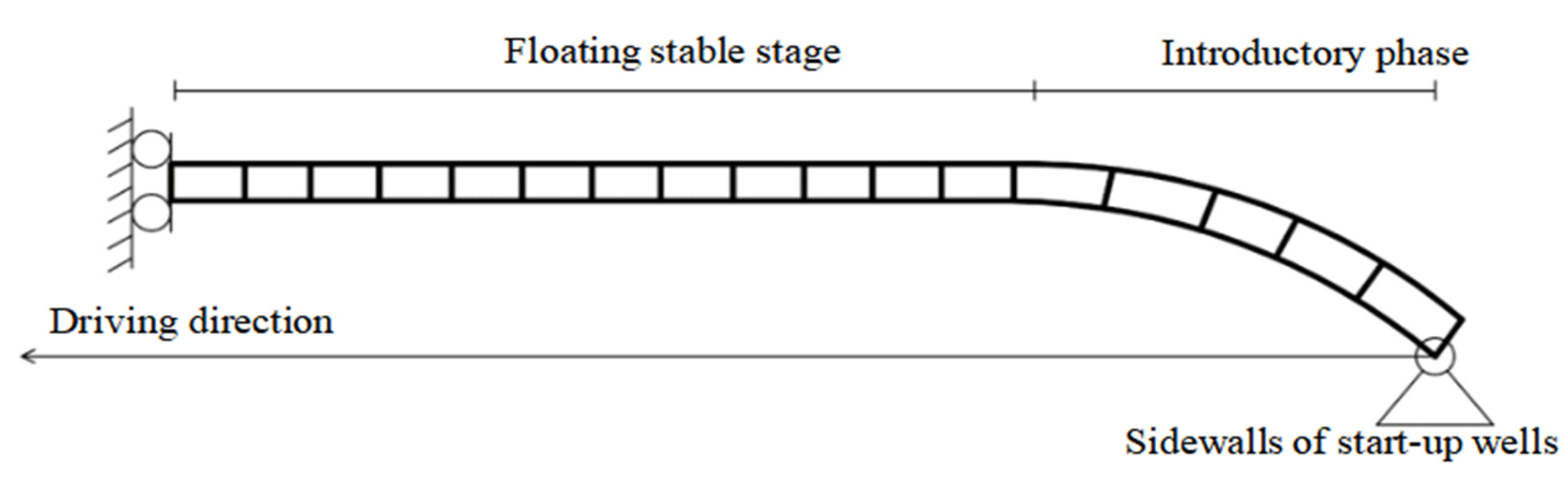
Figure 8.
Geological profile of the Jiangnan start section of the east line of the Yuanjiang Tunnel.
Figure 8.
Geological profile of the Jiangnan start section of the east line of the Yuanjiang Tunnel.

Figure 9.
Yuanan shield machine cutter of Yuanjiang Tunnel.

Figure 10.
Theoretical calculation of instantaneous uplift of each tunnel section under grouting pressure.
Figure 10.
Theoretical calculation of instantaneous uplift of each tunnel section under grouting pressure.
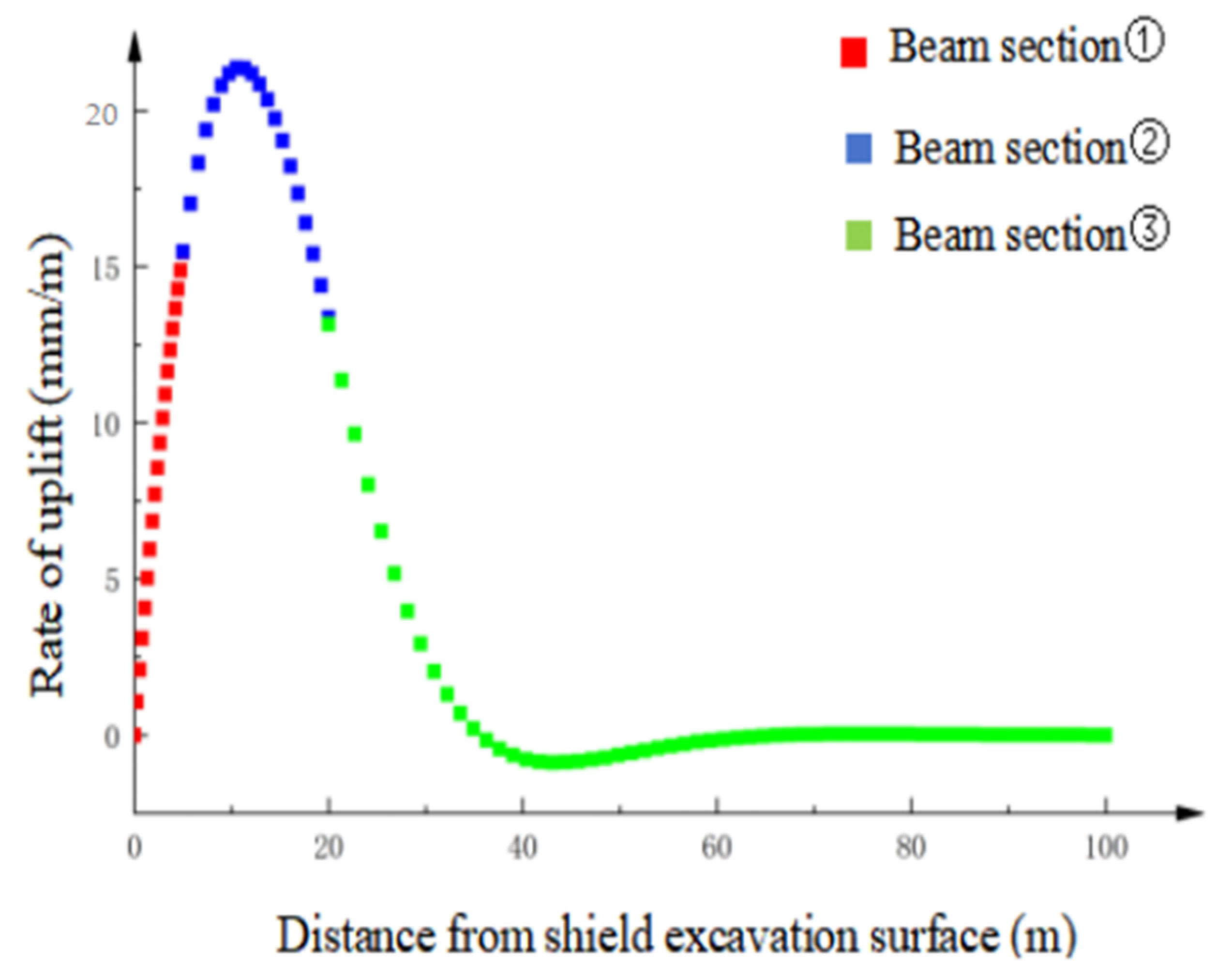
Figure 11.
Distribution of cumulative uplift under equivalent uplift force.

Figure 12.
Distribution of surface monitoring points and laying diagrams. (a) Devices for monitoring vertical surface displacements. (b) Distribution of surface deformation monitoring points (Jiangnan start section).
Figure 12.
Distribution of surface monitoring points and laying diagrams. (a) Devices for monitoring vertical surface displacements. (b) Distribution of surface deformation monitoring points (Jiangnan start section).

Figure 13.
Surface settlement monitoring curves of the east shield interval. (a) Monitoring point DBC1 time-settlement deformation folding line. (b) Monitoring point DBC2 time-settlement deformation folding line. (c) Monitoring point DBC3 time-settlement deformation folding line. (d) Monitoring point DBC6 time-settlement deformation folding line. (e) Monitoring point DBC7 time-settlement deformation folding line. (f) Monitoring point DBC8 time-settlement deformation folding line. (g) Monitoring point DBC9 time-settlement deformation folding line.

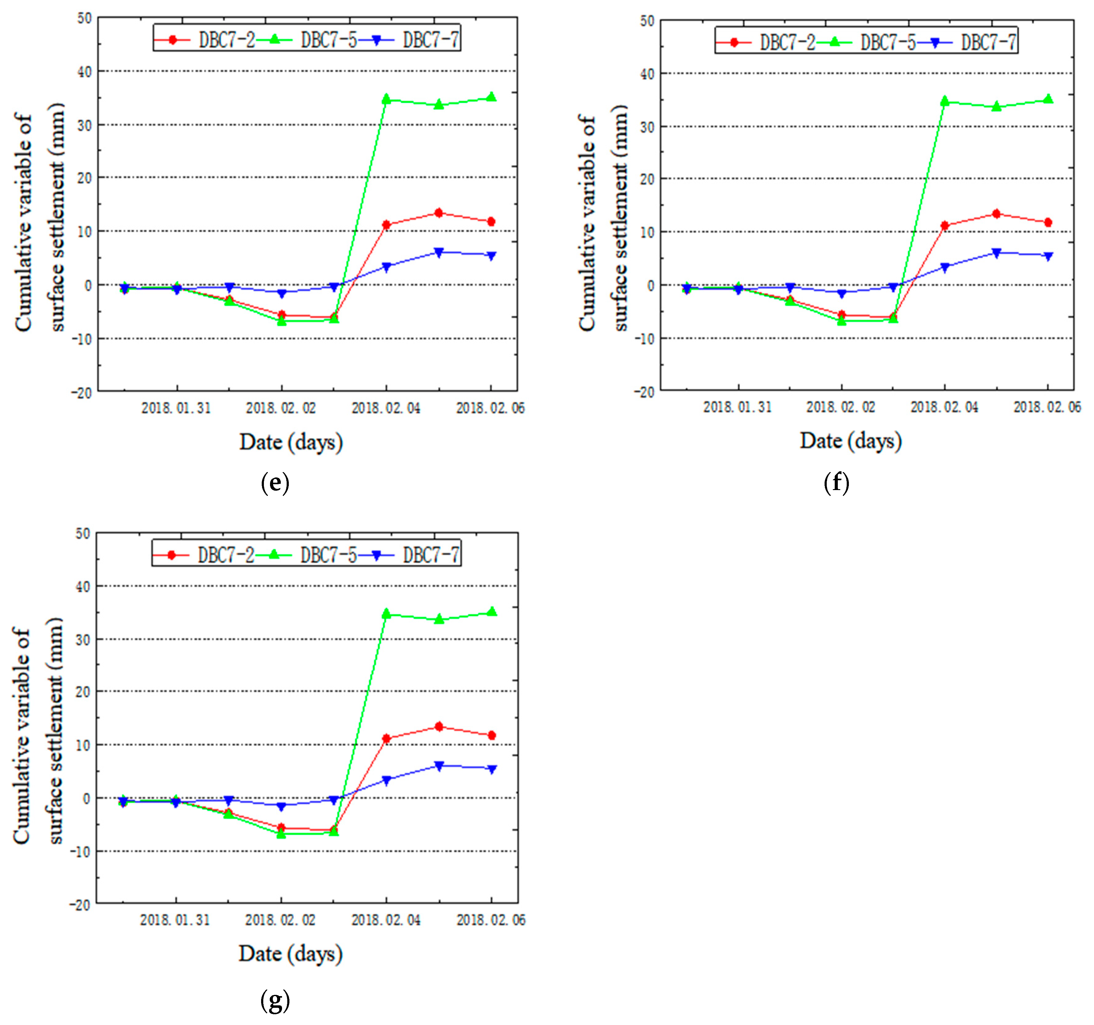
Figure 14.
Surface Deformation Monitoring Values of Tunnel Axis in the Jiangnan Start Section of the Eastern Route.
Figure 14.
Surface Deformation Monitoring Values of Tunnel Axis in the Jiangnan Start Section of the Eastern Route.
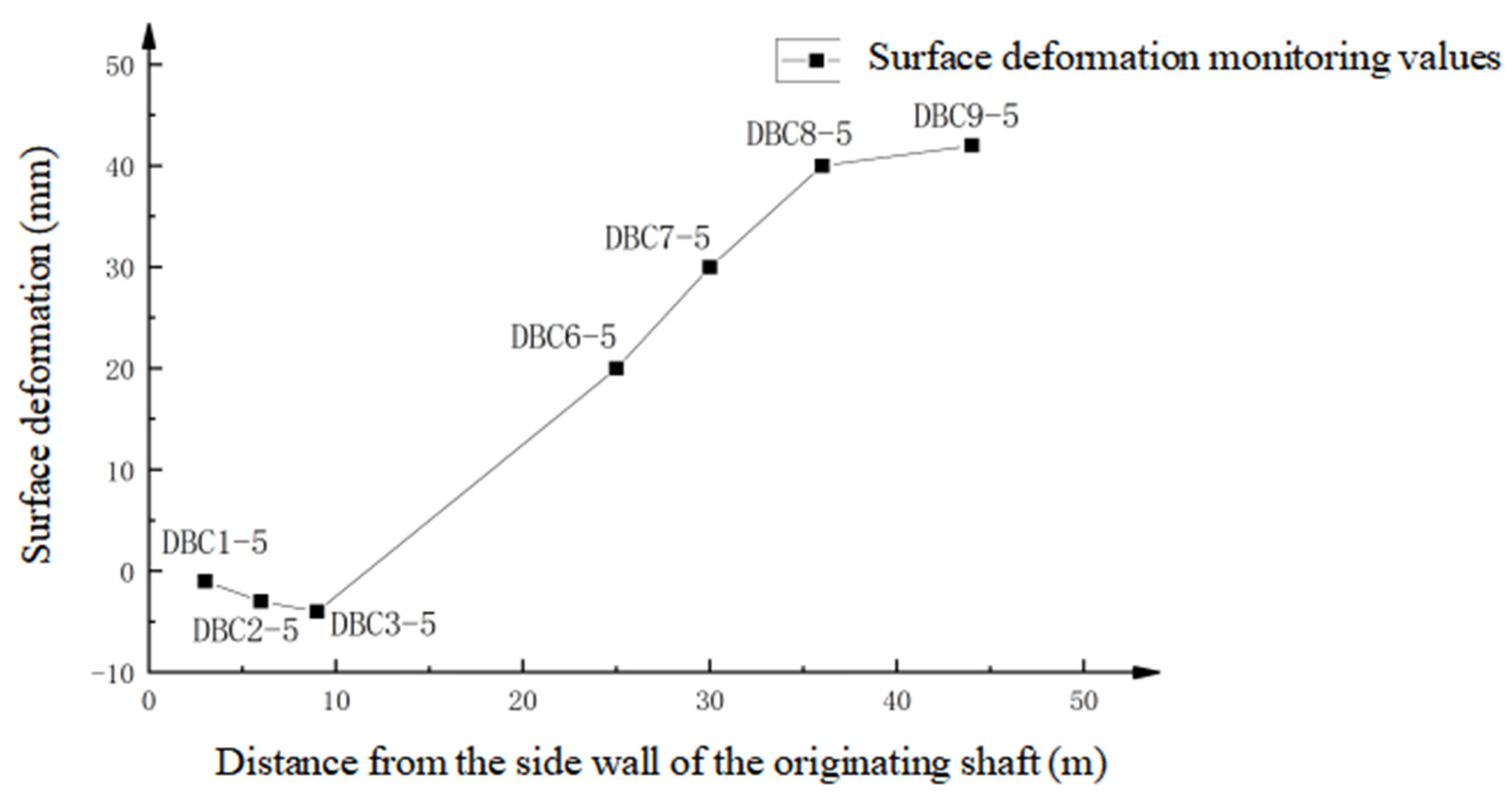
Figure 15.
Comparison between the theoretical calculation of tunnel uplift and surface deformation monitoring values.
Figure 15.
Comparison between the theoretical calculation of tunnel uplift and surface deformation monitoring values.

Disclaimer/Publisher’s Note: The statements, opinions and data contained in all publications are solely those of the individual author(s) and contributor(s) and not of MDPI and/or the editor(s). MDPI and/or the editor(s) disclaim responsibility for any injury to people or property resulting from any ideas, methods, instructions or products referred to in the content. |
© 2024 by the authors. Licensee MDPI, Basel, Switzerland. This article is an open access article distributed under the terms and conditions of the Creative Commons Attribution (CC BY) license (https://creativecommons.org/licenses/by/4.0/).
Share and Cite
MDPI and ACS Style
Wu, J.; Chen, J. Experimental Research on the Floating Amount of Shield Tunnel Based on the Innovative Cumulative Floating Amount Calculation Method. Buildings 2024, 14, 1228. https://doi.org/10.3390/buildings14051228
AMA Style
Wu J, Chen J. Experimental Research on the Floating Amount of Shield Tunnel Based on the Innovative Cumulative Floating Amount Calculation Method. Buildings. 2024; 14(5):1228. https://doi.org/10.3390/buildings14051228
Chicago/Turabian StyleWu, Jingrong, and Jing Chen. 2024. "Experimental Research on the Floating Amount of Shield Tunnel Based on the Innovative Cumulative Floating Amount Calculation Method" Buildings 14, no. 5: 1228. https://doi.org/10.3390/buildings14051228
Note that from the first issue of 2016, this journal uses article numbers instead of page numbers. See further details here.