
Assessment of the Performance of a Ventilated Window Coupled with a Heat Recovery Unit through the Co-Heating Test

 , ,
, , 
Abstract
:1. Introduction
2. Experimental Section
2.1. Description of the Test Cells


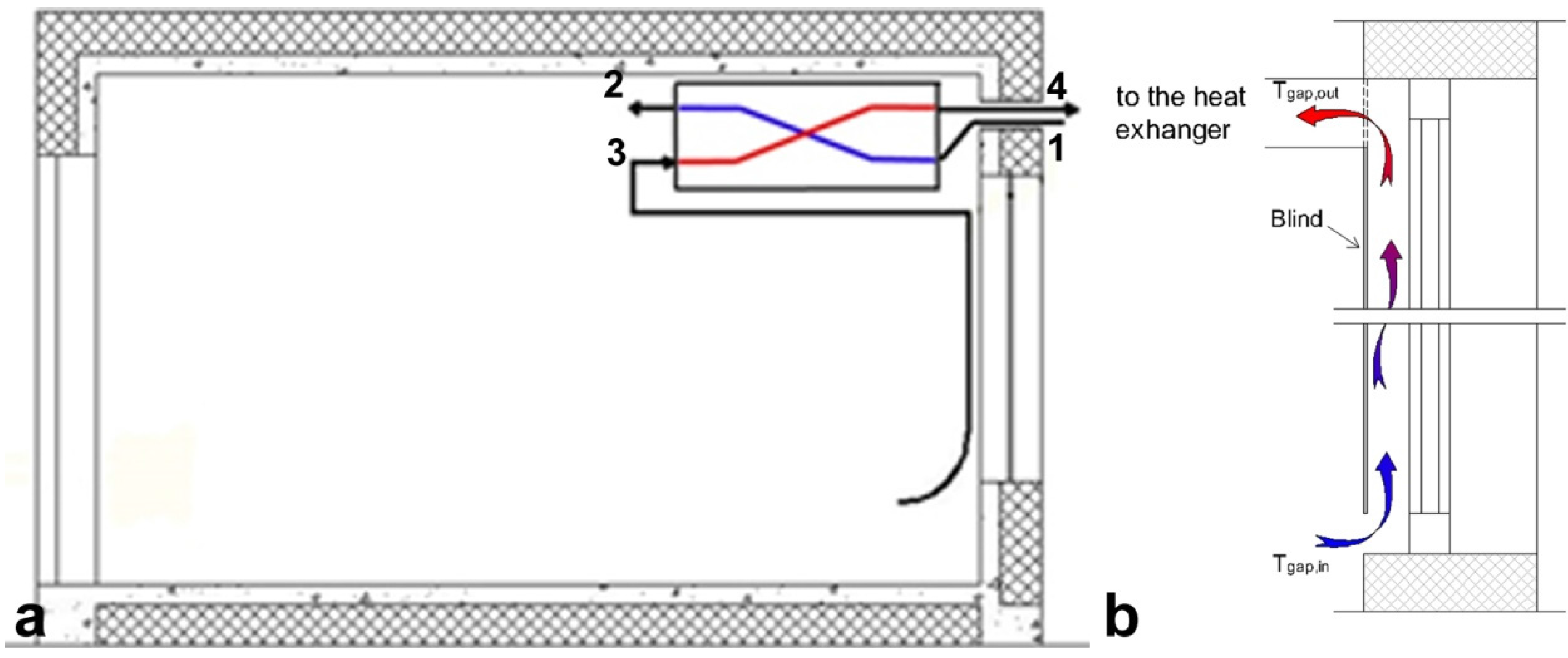
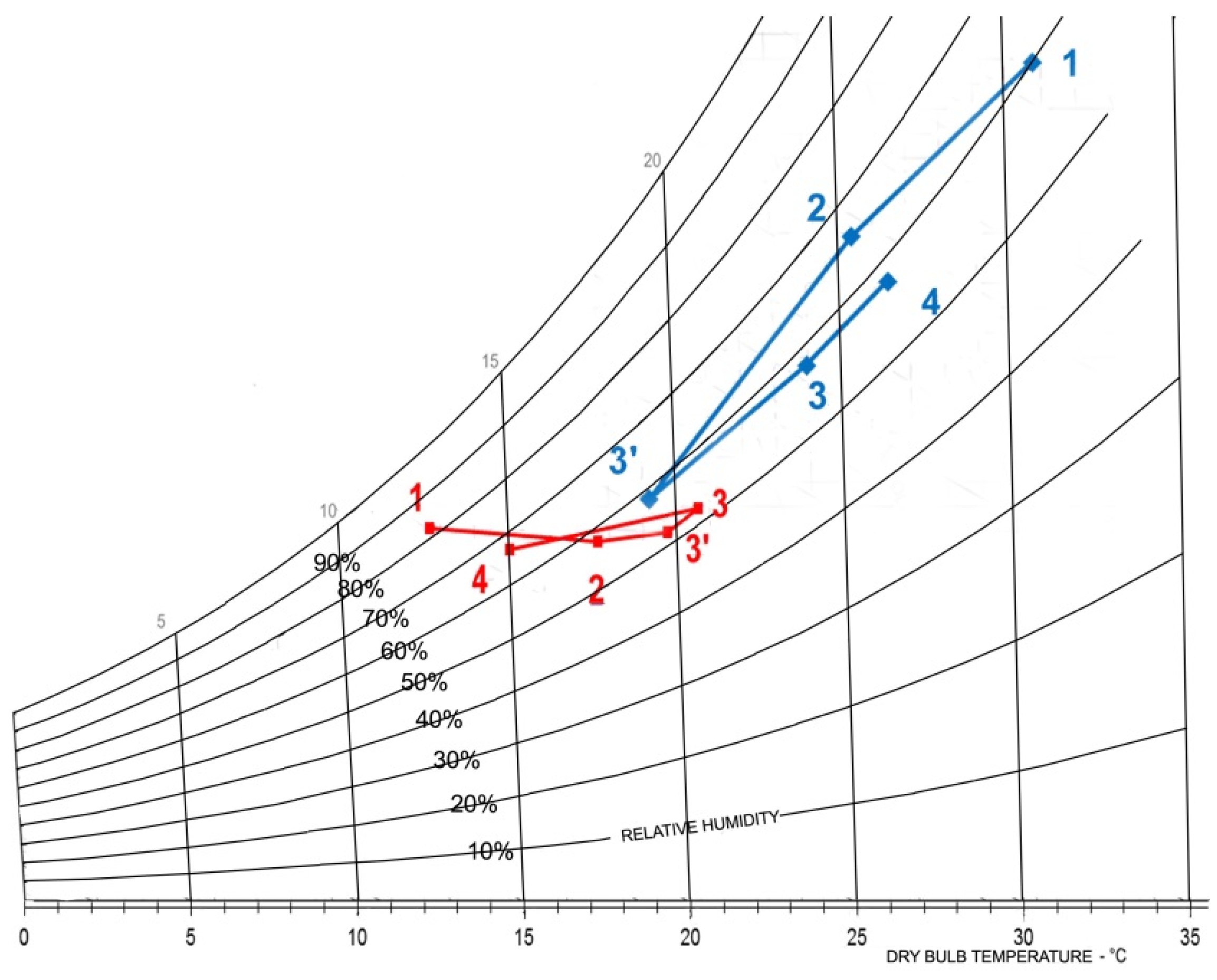
- point 1 is the inlet airflow from the outside;
- point 2 is the heat recovery unit airflow to the inside;
- point 3 is the intake airflow of the heat recovery unit from the inside, after passing through the ventilated gap of the window;
- point 4 represents the heat recovery unit airflow to the outside.

| Code | Heating | Cooling | Heat Exchanger |
|---|---|---|---|
| Heating | On | Off | On |
| Cooling | Off | On | On |
| Comfort | Off | Off | On |
2.2. Calibration of the Test Cells


3. Results and Discussion
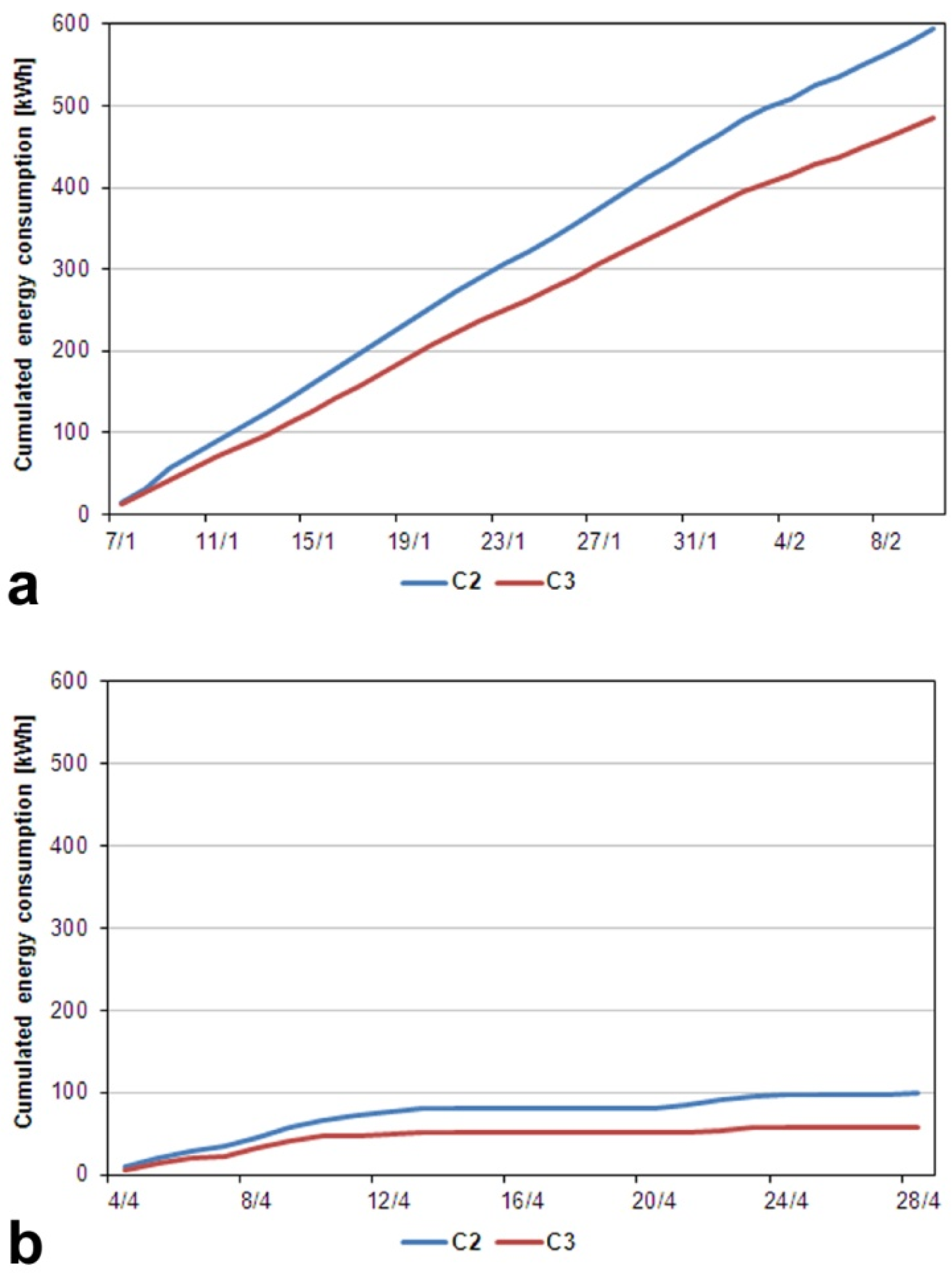
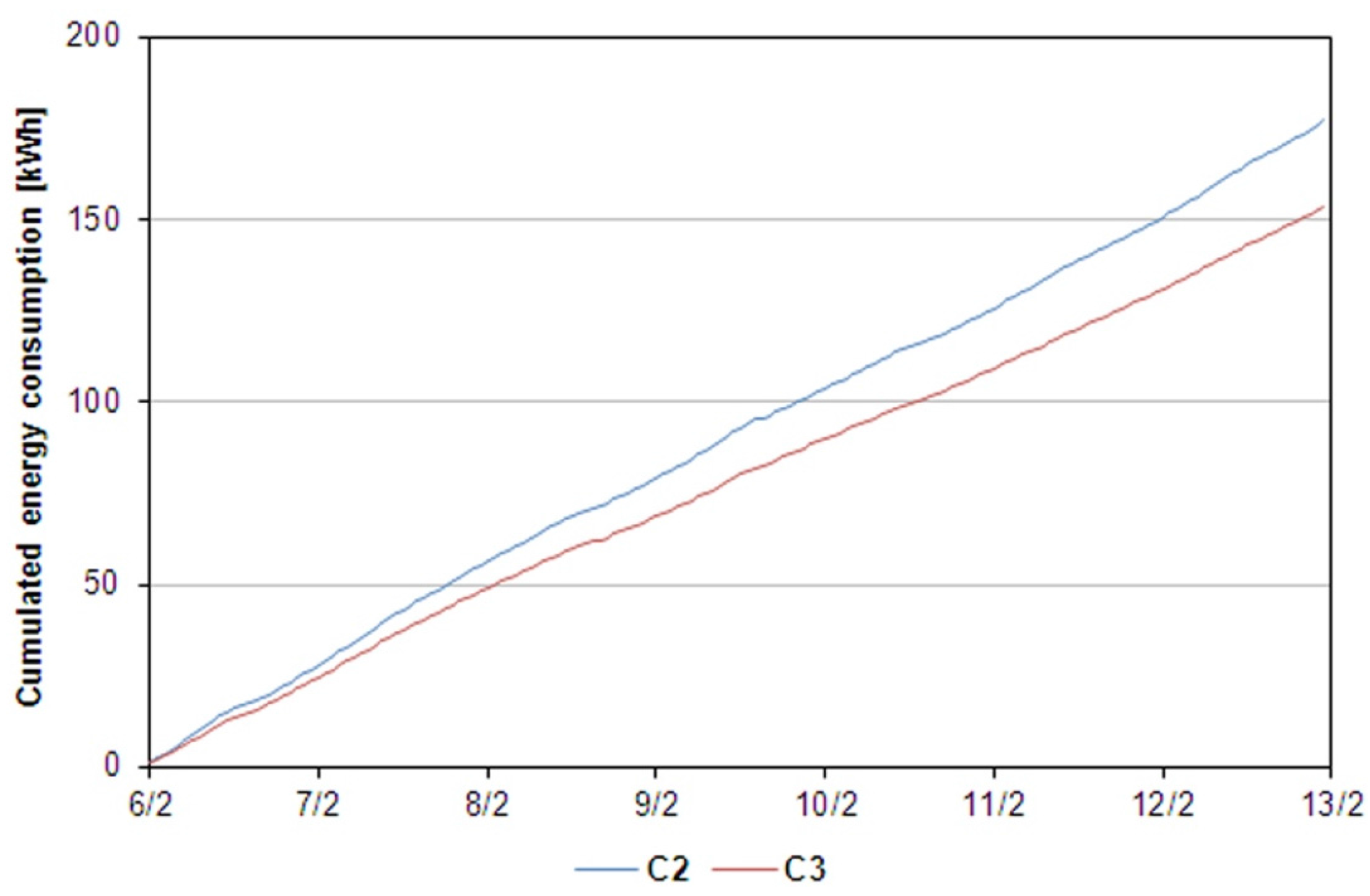
3.1. Assessment of the Energy Consumption
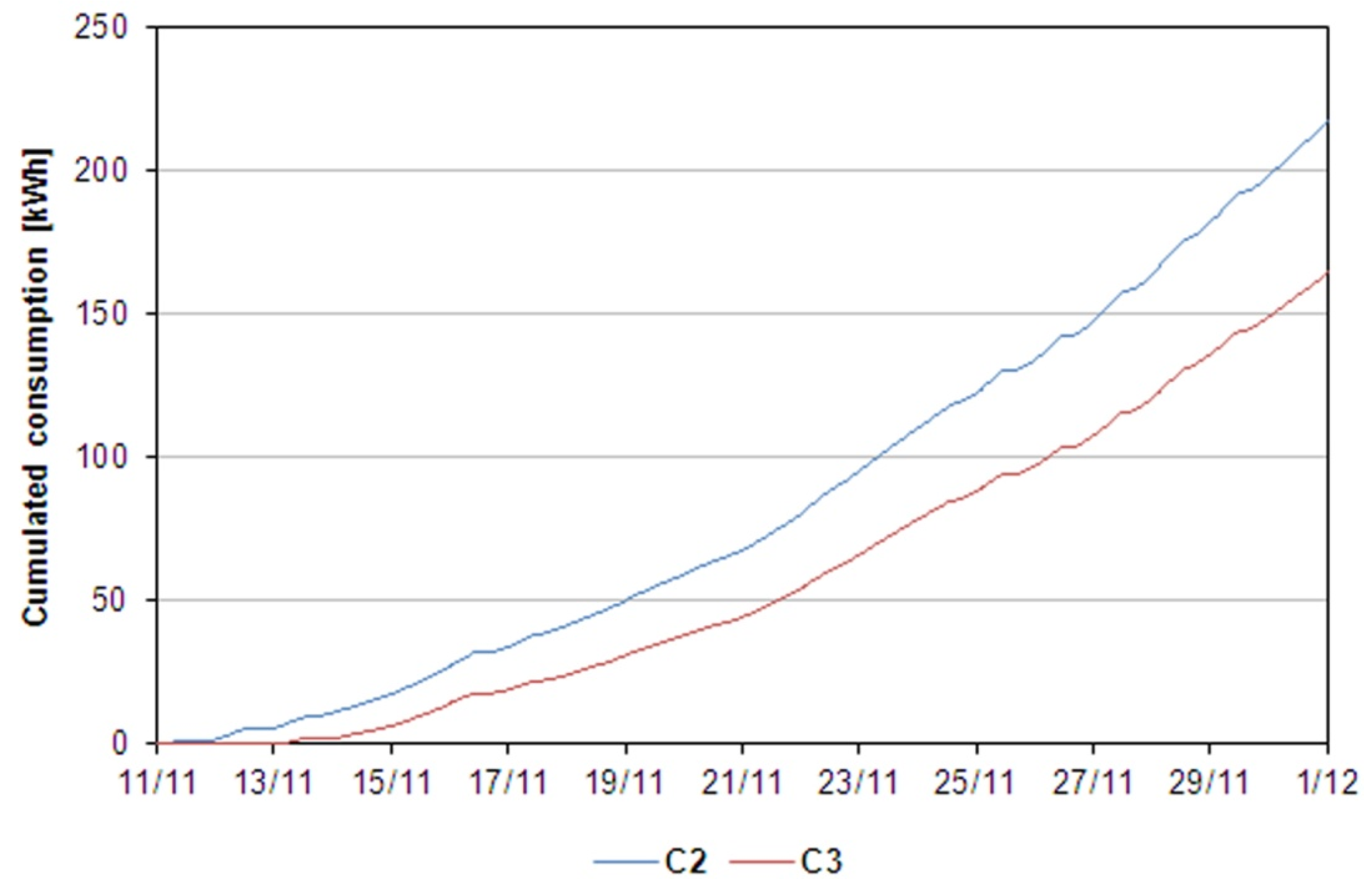
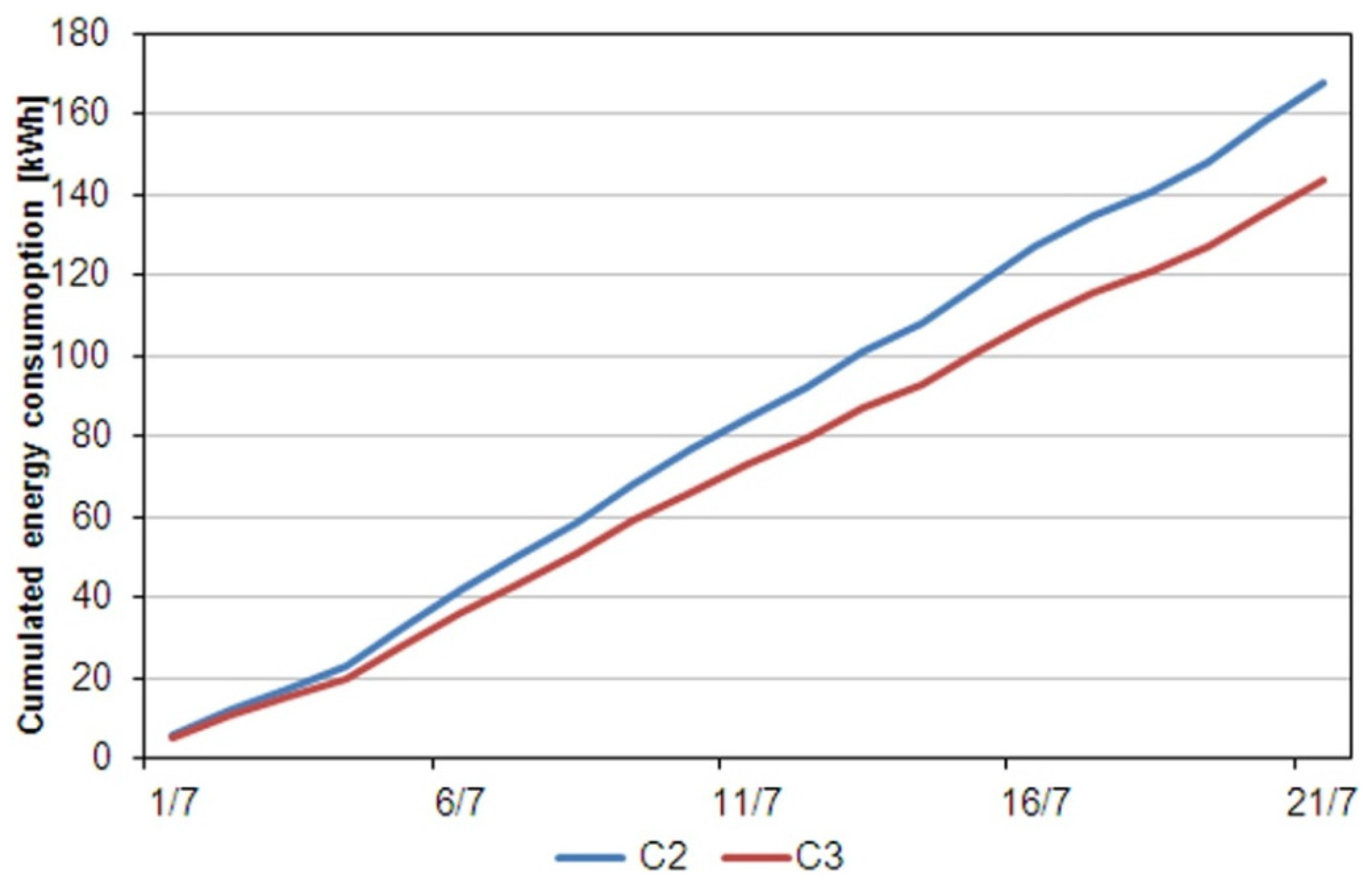
- Cumulated consumption;
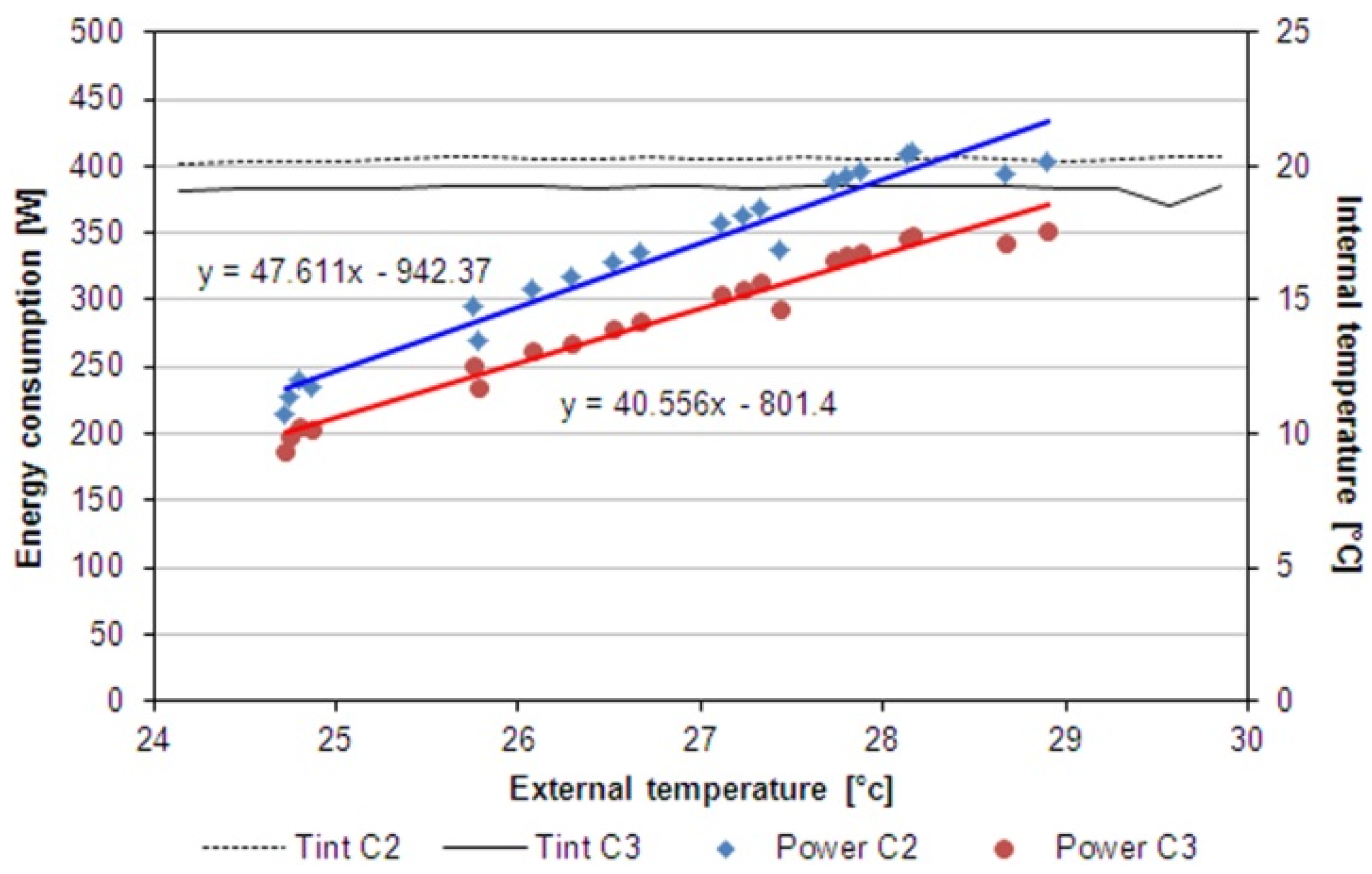
- Energy Signature method.
| Configuration | Period | External Temperature (°C) | Solar Radiation (W/m2) | |||
|---|---|---|---|---|---|---|
| Min | Max | Avg | Max | Avg | ||
| (a) Heating | 7 January–11 February | −3.91 | 12.87 | 2.88 | 552 | 192 |
| (b) Heating | 4–30 April | 0.9 | 29.16 | 14.51 | 915 | 371 |
| (c) Cooling | 1–21 July | 10.97 | 34.88 | 24.51 | 955 | 491 |
3.1.1. Heating Configuration

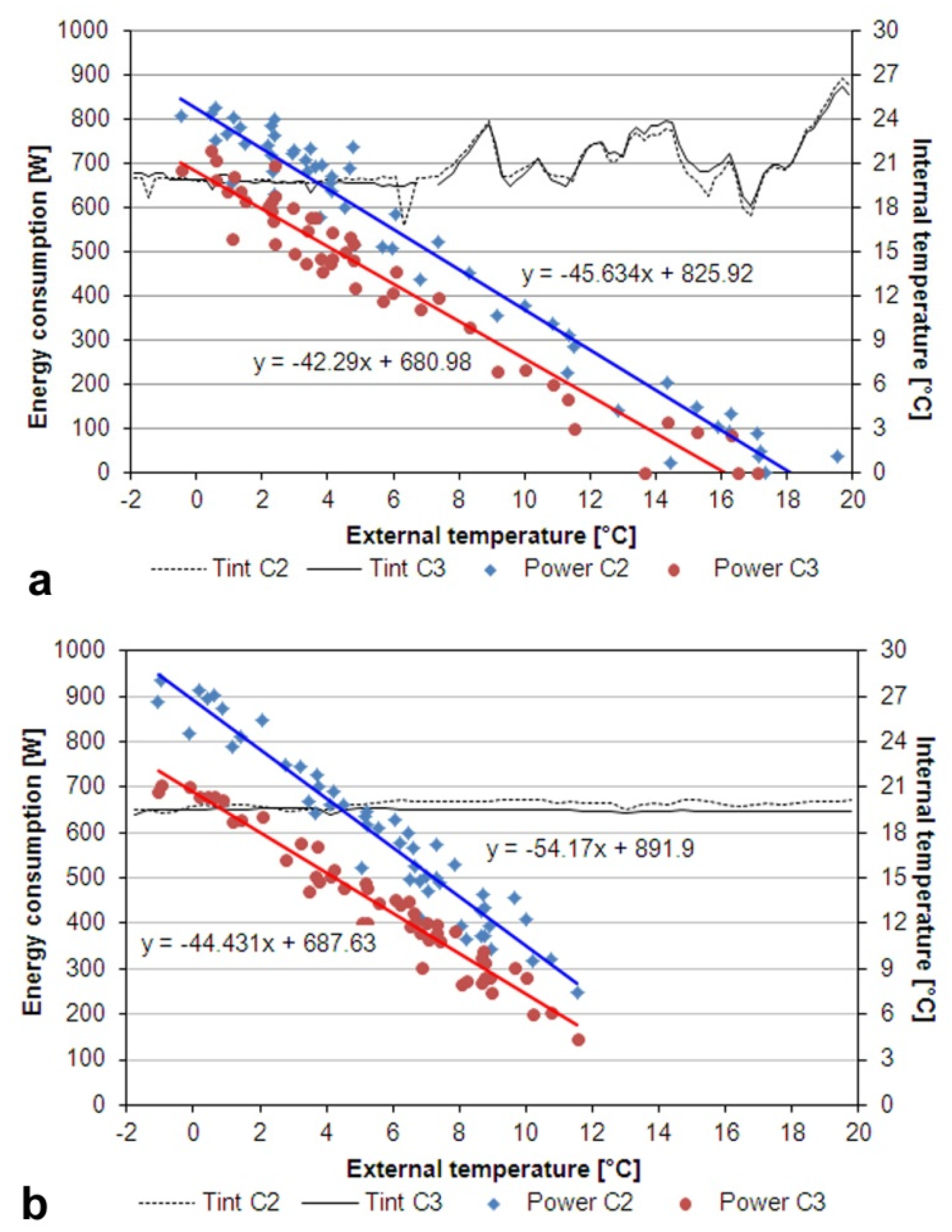
3.1.2. Cooling Configuration


3.2. Thermal Comfort Evaluation
- segments 1–2 represent the process of the heat exchange from outside to inside by the recovery unit that exchanges heat with outgoing airflow;
- segment 2–3’ show the process of heating or cooling of the internal ambient by the plant;
- segment 3’–3 are the overheating of the ambient air passing through the ventilated gap of the window;
- segment 3–4 indicate the process of the heat exchange of the air from the inlet airflow in the recovery unit to outside giving heat incoming airflow.
3.3. Efficiency of the Coupled System
- heat recovery;
- heat exchange reduction;
- integrated action of pre-heating in the dynamic windows before the heat recovery unit.

4. Conclusions
Acknowledgments
Author Contributions
Conflicts of Interest
References
- Torcal, F.P.; Mistretta, M.; Kaklauskas, A.; Granqvist, C.G. Nearly Zero Energy Building Refurbishment—A Multidisciplinary Approach; Springer: London, UK, 2013. [Google Scholar]
- Popescu, D.; Bienert, S.; Schutzenhofer, C.; Boazu, R. Impact of energy efficiency measures on the economic value of buildings. Appl. Energy 2012, 89, 454–463. [Google Scholar] [CrossRef]
- Xing, Y.; Hewitt, N.; Griffiths, P. Zero carbon buildings refurbishment—A hierarchical pathway. Renew. Sustain. Energy Rev. 2011, 15, 3229–3236. [Google Scholar] [CrossRef]
- Directive 2012/27/EU of the European Parliament and of the Council of 25 October 2012 on Energy Efficiency, Amending Directives 2009/125/EC and 2010/30/EU and Repealing Directives 2004/8/EC and 2006/32/EC; The European Parliament and of the Council: Brussels, Belgium, 2012.
- Data Elaborated from IEA Statistics. Available online: http://www.iea.org/ (accessed on 12 December 2015).
- Kneifel, J. Life-cycle carbon and cost analysis of energy efficiency measures in new commercial buildings. Energy Build. 2010, 42, 333–340. [Google Scholar] [CrossRef]
- Pérez-Lombard, L.; Ortiz, J.; Pout, C. A review on buildings energy consumption information. Energy Build. 2008, 40, 394–398. [Google Scholar] [CrossRef]
- Allouhi, A.; el Fouih, Y.; Kousksou, T.; Jamil, A.; Zeraouli, Y.; Mourad, Y. Energy consumption and efficiency in buildings: Current status and future trends. J. Clean. Prod. 2015, in press. [Google Scholar] [CrossRef]
- Aste, N.; Caputo, P.; Buzzetti, M.; Fattore, M. Energy efficiency in buildings: What drives the investments? The case of Lombardy Region. Sustain. Cities Soc. 2016, 20, 27–37. [Google Scholar] [CrossRef]
- Ma, P.; Wang, L.S.; Guo, N. Maximum window-to-wall ratio of a thermally autonomous building as a function of envelope U-value and ambient temperature amplitude. Appl. Energy 2015, 146, 84–91. [Google Scholar] [CrossRef]
- Kull, T.M.; Mauring, T.; Tkaczyk, A.H. Energy balance calculation of window glazings in the northern latitudes using long-term measured climatic data. Energy Convers. Manag. 2015, 89, 896–906. [Google Scholar] [CrossRef]
- Feist, W.; Schnieders, J.; Dorer, V.; Haas, A. Re-inventing air heating: Convenient and comfortable within the frame of the Passive House concept. Energy Build. 2005, 37, 1186–1203. [Google Scholar] [CrossRef]
- Lollini, R.; Danza, L.; Meroni, I. Energy efficiency of a dynamic glazing system. Sol. Energy 2010, 84, 526–537. [Google Scholar] [CrossRef]
- Bauwns, G.; Roels, S. Co-heating test: A state-of-the-art. Energy Build. 2014, 82, 163–172. [Google Scholar] [CrossRef]
- Belussi, L.; Danza, L. Method for the prediction of malfunctions of buildings through real energy consumption analysis: Holistic and multidisciplinary approach of Energy Signature. Energy Build. 2012, 55, 715–720. [Google Scholar] [CrossRef]
- American Society of Heating, Refrigerating and Air-Conditioning Engineers. Thermal comfort. In 2009 ASHRAE Handbook Fundamentals; American Society of Heating, Refrigerating and Air-Conditioning Engineers, Inc.: Atlanta, GA, USA, 2009; Chapter 9. [Google Scholar]
- EN ISO 12569:2012 Thermal Performance of Buildings and Materials—Determination of Specific Airflow Rate in Buildings—Tracer Gas Dilution Method; CEN-European Committee for Standardization: Brussels, Belgium, 2012.
- EN 15603:2008 For Space Heating—Overall Energy Use and Definition of Energy Ratings; CEN-European Committee for Standardization: Brussels, Belgium, 2012.
- Nordström, G.; Johnsson, H.; Lidelöw, S. Using the energy signature method to estimate the effective U-value of buildings. Sustain. Energy Build. 2013, 22, 35–44. [Google Scholar]
- Zhao, H.X.; Magoulès, F. A review on the prediction of building energy consumption. Renew. Sustain. Energy Rev. 2012, 16, 3586–3592. [Google Scholar] [CrossRef]
- Sjogren, J.U.; Andersson, S.; Olofsson, T. Sensitivity of the total heat loss coefficient determined by the energy signature approach to different time periods and gained previous energy. Energy Build. 2009, 41, 801–808. [Google Scholar] [CrossRef]
- Belussi, L.; Danza, L.; Meroni, I.; Salamone, F. Energy performance assessment with empirical methods: Application of energy signature. Opto-Electron. Rev. 2015, 23, 85–89. [Google Scholar] [CrossRef]
- ANSI/ASHRAE Standard 55 Thermal Environmental Conditions for Human Occupancy; American Society of Heating, Refrigerating and Air-Conditioning Engineering, Inc.: Atlanta, GA, USA, 2013.
- McEvoy, M.E.; Southall, R.G.; Baker, P.H. Test cell evaluation of supply air windows to characterise their optimum performance and its verification by the use of modelling techniques. Energy Build. 2003, 35, 1009–1020. [Google Scholar] [CrossRef]
© 2016 by the authors; licensee MDPI, Basel, Switzerland. This article is an open access article distributed under the terms and conditions of the Creative Commons by Attribution (CC-BY) license (http://creativecommons.org/licenses/by/4.0/).
Share and Cite
Danza, L.; Barozzi, B.; Belussi, L.; Meroni, I.; Salamone, F. Assessment of the Performance of a Ventilated Window Coupled with a Heat Recovery Unit through the Co-Heating Test. Buildings 2016, 6, 3. https://doi.org/10.3390/buildings6010003
Danza L, Barozzi B, Belussi L, Meroni I, Salamone F. Assessment of the Performance of a Ventilated Window Coupled with a Heat Recovery Unit through the Co-Heating Test. Buildings. 2016; 6(1):3. https://doi.org/10.3390/buildings6010003
Chicago/Turabian StyleDanza, Ludovico, Benedetta Barozzi, Lorenzo Belussi, Italo Meroni, and Francesco Salamone. 2016. "Assessment of the Performance of a Ventilated Window Coupled with a Heat Recovery Unit through the Co-Heating Test" Buildings 6, no. 1: 3. https://doi.org/10.3390/buildings6010003
APA StyleDanza, L., Barozzi, B., Belussi, L., Meroni, I., & Salamone, F. (2016). Assessment of the Performance of a Ventilated Window Coupled with a Heat Recovery Unit through the Co-Heating Test. Buildings, 6(1), 3. https://doi.org/10.3390/buildings6010003