1. Introduction
In recent years, the appeal for the application of renewable energy sources has increased, given the awareness on environmental issues, such as climate change and greenhouse gas emission. This pressure for clean and environmentally-friendly energy, along with the liberalized electric market, and the demand of efficient, reliable, and diversified energy sources, have led to an increasing interest in renewable power generation [
1]. The microgrid approach was designed as a bridge technology towards the smart grid system that intends to increase small-scale energy generation and minimize the energy cost [
2].
The low power generation capacity on distributed sources has motivated the integration of distributed generation units aiming to increase power generator capacity, but since most distributed generation units, especially renewable distributed generation units, produce an intermittent power, the application of distributed generation units without a distributed storage system severely curtails the renewable energy penetration [
3]. Given this limitation, power electronics devices have become a key point in microgrid development [
4].
To overcome this limitation, and aiming to develop a bridge technology towards the future smart grid, the microgrid grid concept was proposed. The microgrid systems can be classified in three different groups given its architecture. AC microgrid systems adopt the voltage and frequency standards applied in most conventional distribution systems [
4]; the DC microgrid, idealized to be used in environments where DC loads are becoming predominant; and a hybrid microgrid working with two different buses, one AC and one DC. This paper is concerned about DC microgrid architectures. The operation of a DC microgrid is similar to the AC microgrid system and the continuous approach is mainly adopted to use the DC energy generated by the renewable distributed generation units in its natural form. By adopting the DC microgrid solution, part of the conversions necessary in the AC architecture can be avoided increasing the overall efficiency of the system. Nevertheless, in the DC architecture, a conversion is necessary at the point of common coupling (PCC) to be able to exchange power with the main grid [
5]. Since photovoltaic (PV) panels have grown as one of the most commonly used renewable sources in urban areas, and DC loads could become predominant in commercial buildings [
6], the DC microgrid architecture is proposed and studied in a grid-connected configuration using PV energy as the renewable source and an electrochemical storage system. The control strategies may comprehend just the local control, based on local measures, a power management strategy, included in centralized and decentralized approaches, or more layers, such as in the present work where an optimization layer is implemented.
The challenges faced to implement the microgrid concept, regardless of the type of microgrid, are depicted in [
7], where the fact that the integration of distributed generators/loads and interaction between all nodes within a microgrid substantially increases the complexity of control techniques, communication, and power system technology is highlighted, reflecting on many questions about power quality, protection, stability, reliability, and efficiency. In addition to the already presented general challenges, and considering the intended use of the microgrid concept in commercial building applications, some new challenges are presented in [
8]. The management and engineering operations of these buildings typically include end-user operations, heating ventilation and air conditioning, etc. This system is designed to perform the control of those units independently from each other, therefore, the absence of an integrated unit is presented in [
8] as one of the major issues to the application of the microgrid concept in commercial buildings.
The power exchanged with the main grid and the storage system are mainly responsible for ensuring the power balance of the system, while coping with the intermittency problems tied with the renewable sources. However, once the operational constraints imposed to the power exchanged with the main grid and the storage system usage are reached, it is necessary to perform a load shedding to ensure the power balance and, therefore, voltage stability.
Load shedding is commonly defined as the amount of load that must be instantly shed, considering operational conditions and priorities. Some of the approaches are based on game theory methods and consider loads with a continuous range of values, ignoring the discrete characteristic of the load power demand [
9,
10,
11,
12,
13]. In [
9] a load control strategy named Distributed Interruptible Load Shedding is presented to share the load shedding necessity among the greatest possible group of users, to minimize the impact to each individual user. The disadvantage of this method is performing a probabilistic characterization of the load based on a Gaussian distribution of what is a possible limitation to certain cases where this distribution does not fit the desired profile, as pointed out by the authors. In [
10], the authors focused on the necessity of performing load shedding in a distributed generation utility, during islanding operation mode, to ensure power balance. A combination of adaptive under-frequency load shedding and state estimation is proposed to solve this problem. In [
11], aiming to replace the conventional load shedding methods, an intelligent approach is proposed. The conventional methods such as: breaker interlock scheme, under-frequency relay and programmable logic controllers described in [
11] are slow and with low accuracy when calculating the amount of load to be shed. The load shedding method proposed in [
11] is based on a computerized power management technology and aims to: recognize different patterns in order to predict the system response; make reliable decisions; and identify the minimum amount of load necessary to maintain system stability. The disadvantages of this method are the requirements to be met to design and tune, such as a knowledge base obtained from offline system simulations, system dependencies, and continually-updated dynamic load shed tables. In [
12], a load shedding approach is proposed for DC microgrid systems; the lack of communication to perform the load shedding is presented as the main advantage of the proposed method. Nevertheless, it becomes impossible to optimize the load shedding behavior, because in this method the appliances are ranked from the lowest to the highest to be shed in order, given the DC voltage fluctuation. In [
13], the concept of a power buffer is introduced, stretching the time scale of the transient dynamic, diminishing the impact of tight converter regulation, and the load shedding is studied in depth to be used as an asset in a DC smart grid structure. Different control strategies are proposed: given the nature of the load, e.g., a resistive load, such as incandescent light, it does not necessarily need to be turned off completely but, instead, the amount of power sent to those sources could be reduced. The control strategy is also influenced by the aforementioned power buffer. If the voltage drops for a long time, the power buffer will not be able to reject this fluctuation and a different action, such as load shedding, is necessary to ensure voltage stability. This paper validates the usage of the load as an asset to perform energy management in DC smart grid systems but has not addressed itself to the optimum load shedding/restoration problem.
This paper aims to improve the DC microgrid approach introduced in [
14,
15] by introducing a demand-side management strategy, based on a more realistic load shedding/restoration algorithm. In [
14] the main goal was to present the concept of an optimized approach to solve the energy management problem in a microgrid environment using a simple load profile with a continuous approach to the load shedding problem. The main focus was to present the supervision structure while the problem of the load shedding and restoration were not addressed. In [
15] the model and concept presented in [
14] were validated in the experimental platform, corroborating the conclusions presented in [
14] and the applicability of the proposed microgrid concept. In [
16], the concept depicted in [
14,
15] was translated to the isolated DC microgrid case, where a micro turbine was assumed to have only two possible states, disconnected or at the rated power, but the problem of load shedding and restoration was not addressed.
Since the designed structure for the presented microgrid system has proven its value, we decided to go one step further, focusing on the load shedding algorithm, in a realistic load profile. Instead of the continuous approach discussed before and presented in [
14,
15,
16] as well, the proposed load shedding approach needs to respect the power, priority, and the discrete dynamic of each connected appliance. Other key aspects of the load shedding algorithm are the optimized load shedding, smart restoration, and a critical load level constraint to be respected ensuring that certain amounts of load shall not be shed under any circumstance.
Section 2 presents the grid-connected DC microgrid system, the supervision strategy, and the operational layer.
Section 3 describes the load shedding/restoration approach and the knapsack optimization problem formulation.
Section 4 describes the results obtained by simulation and gives analysis and discussion, and
Section 5 presents the conclusions.
2. Grid-Connected DC Microgrid System
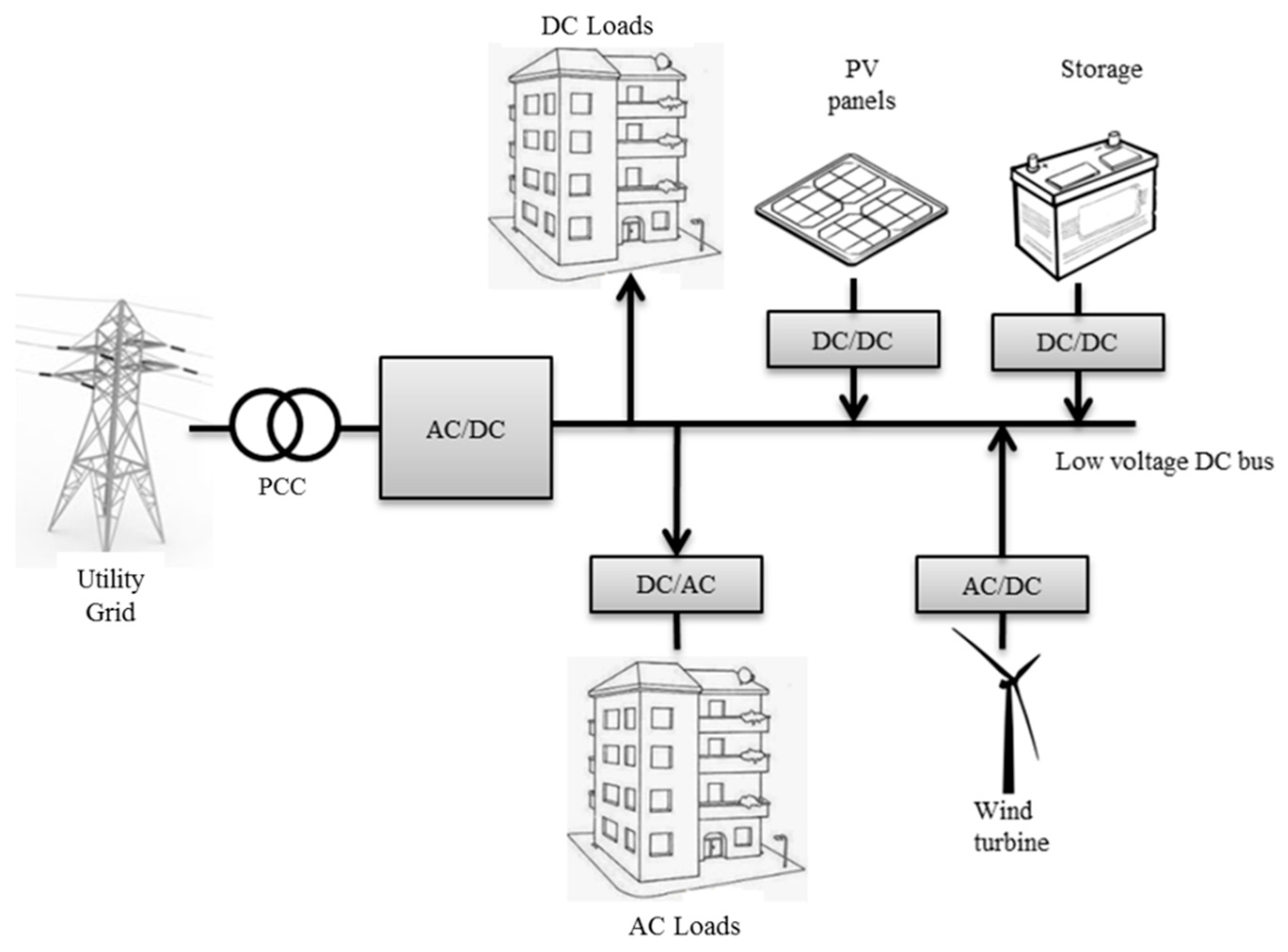
A typical grid-connected DC microgrid, aimed at building integration and increasing the overall efficiency of the system [
1] is presented in
Figure 1. Considering the environments where DC loads are becoming more and more common, e.g., commercial buildings and data centers, the DC microgrid approach becomes more interesting from the energetic efficiency point of view [
16].
The proposed grid-connected DC microgrid consists of PV building-integrated sources, a storage system, and a main grid connection. The bidirectional connections with the main grid and the storage aim to supply the building’s DC appliances, and sell or store the energy surplus.
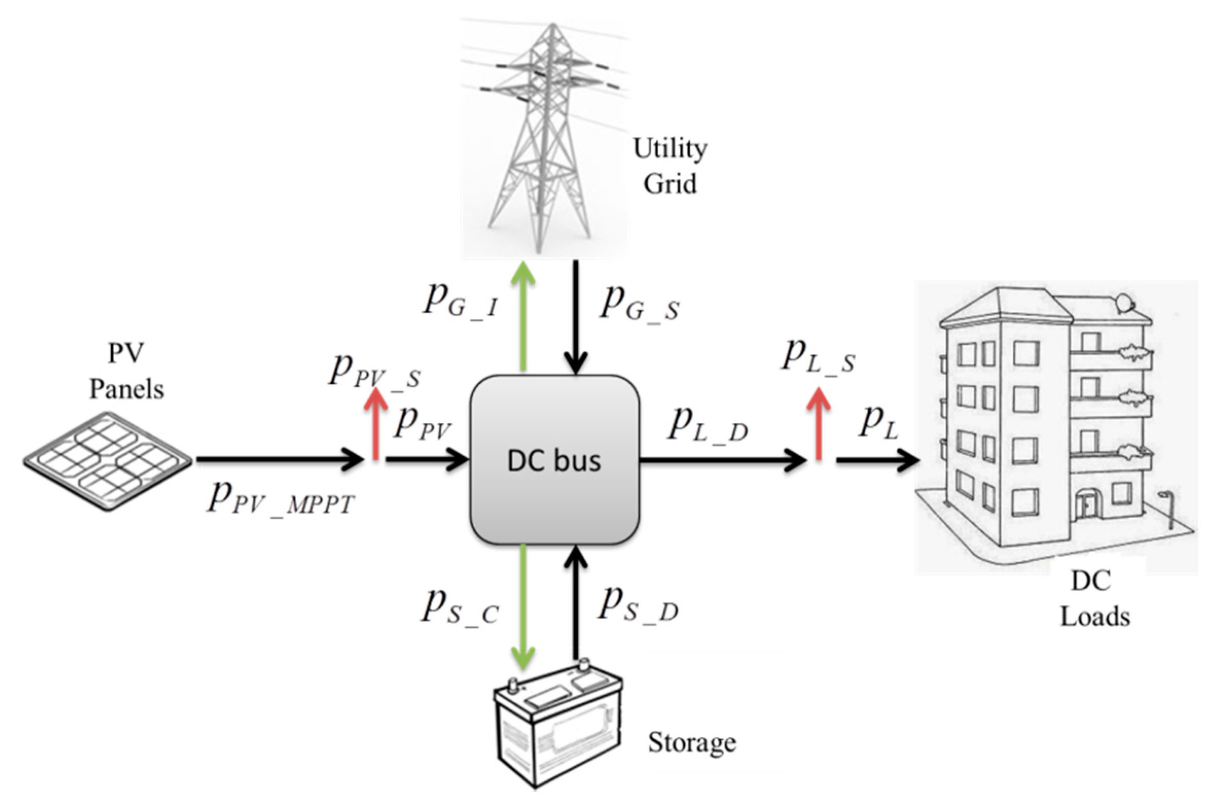
Based on the microgrid power balance and considering that, ideally, the entire load should be supplied and all PV energy should be consumed, the two controllable power sources available to regulate the power balance of the system are the storage and the main grid, respecting the system presented in
Figure 2. Knowing that the storage and main grid are capable of supplying, as well as absorbing, energy from the microgrid, a storage priority strategy is adopted when the storage system is used to supply and to absorb energy from the system; thus, the main grid acts only as a backup source, being used only when the storage system is not capable of attending the system necessities by itself.
It is considered that the microgrid is able to ensure load supply while respecting the main grid limits imposed to the system through smart grid messages. The microgrid is assumed to have the necessary interface to exchange messages with the smart grid. The detailed microgrid power flow can be seen in
Figure 2.
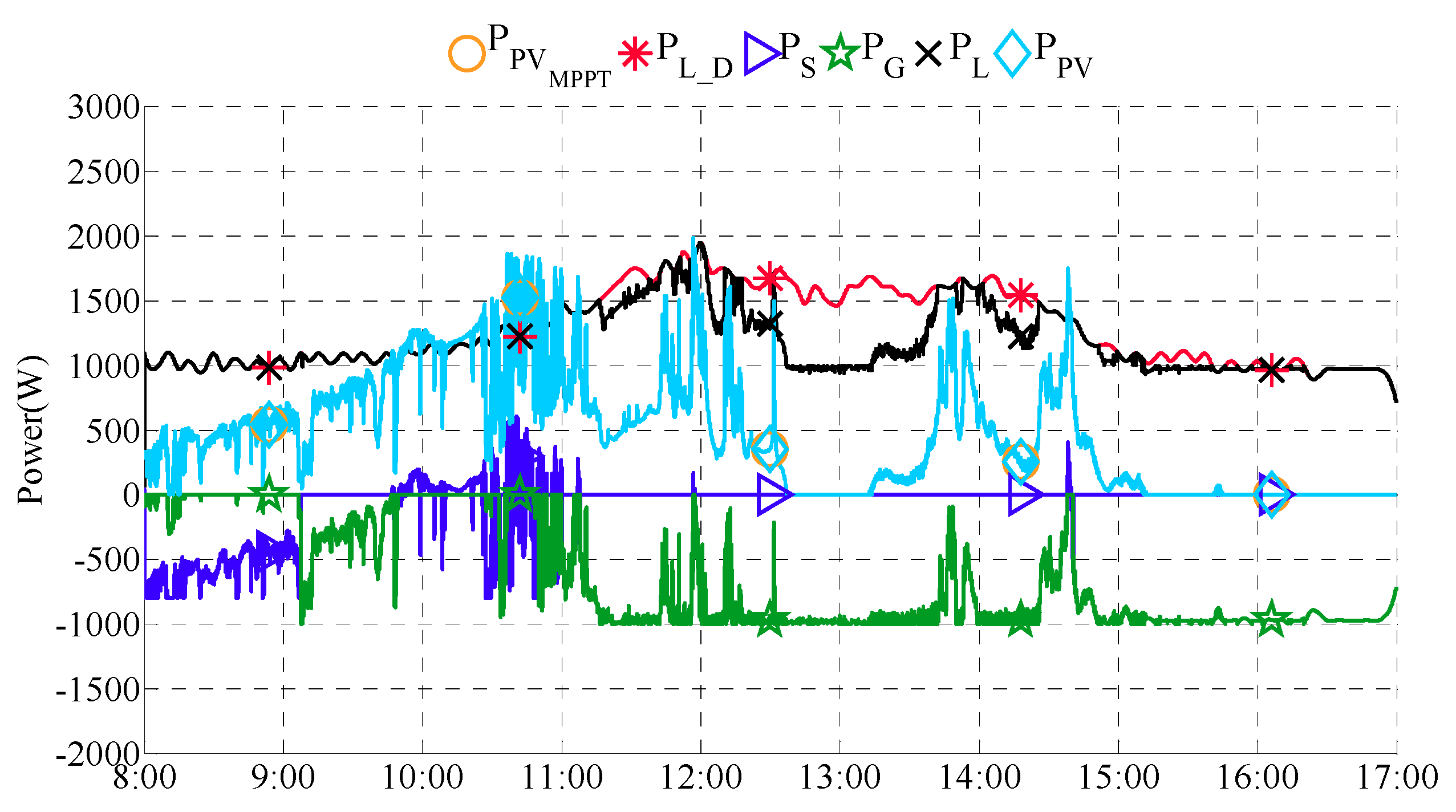
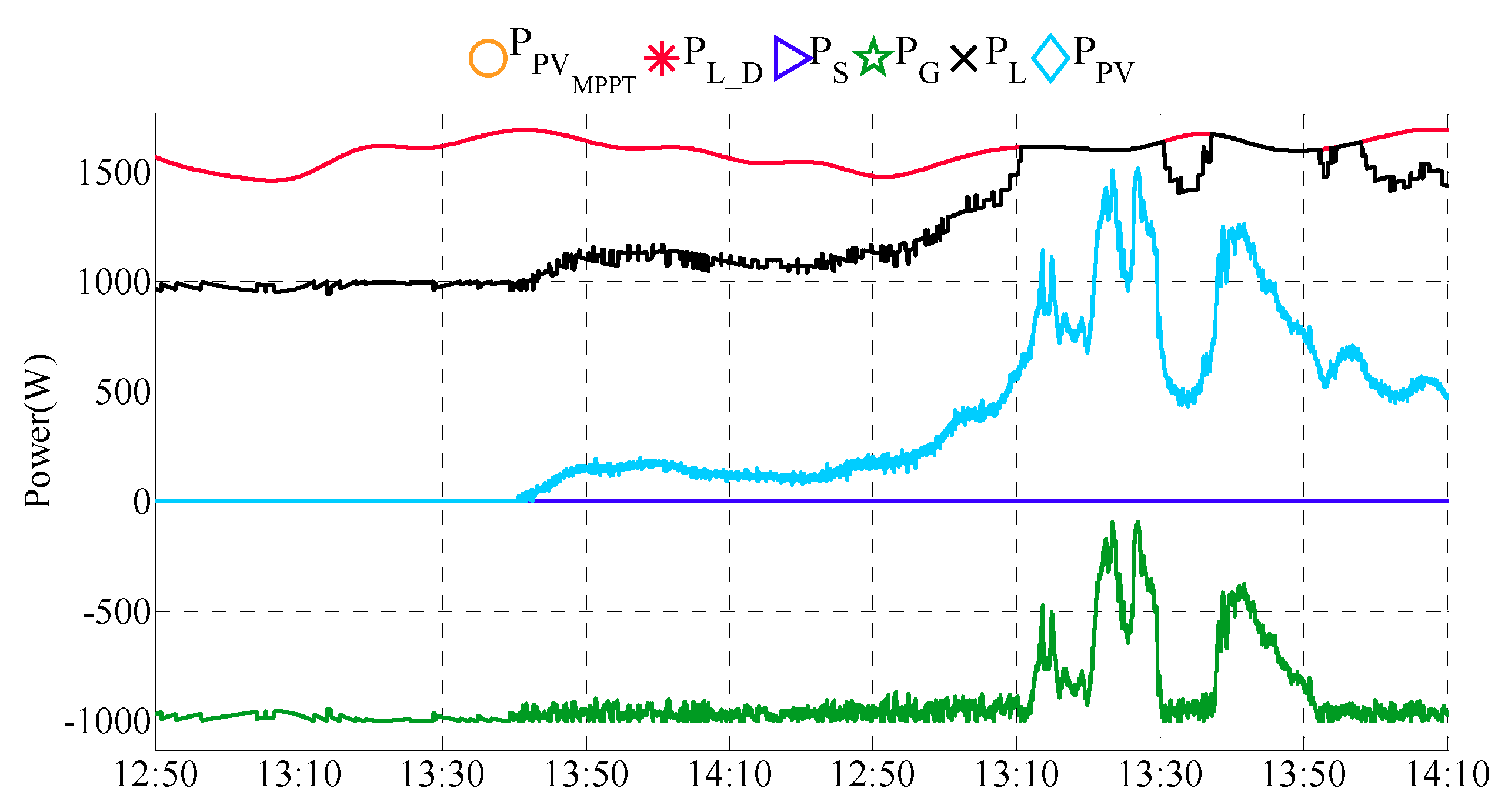
The following powers are used: is the power injected by the microgrid system into the main grid; is the power bought from the main grid; represents the total load power demand; is the amount of load power shed; is the load power demand supplied by the system; is the power taken from the storage system, discharging it; is the power injected into the storage system, charging it; is the instant maximum power production from the PV system; is the PV power shed; and is the PV power consumed by the microgrid system.
2.1. Supervisory System
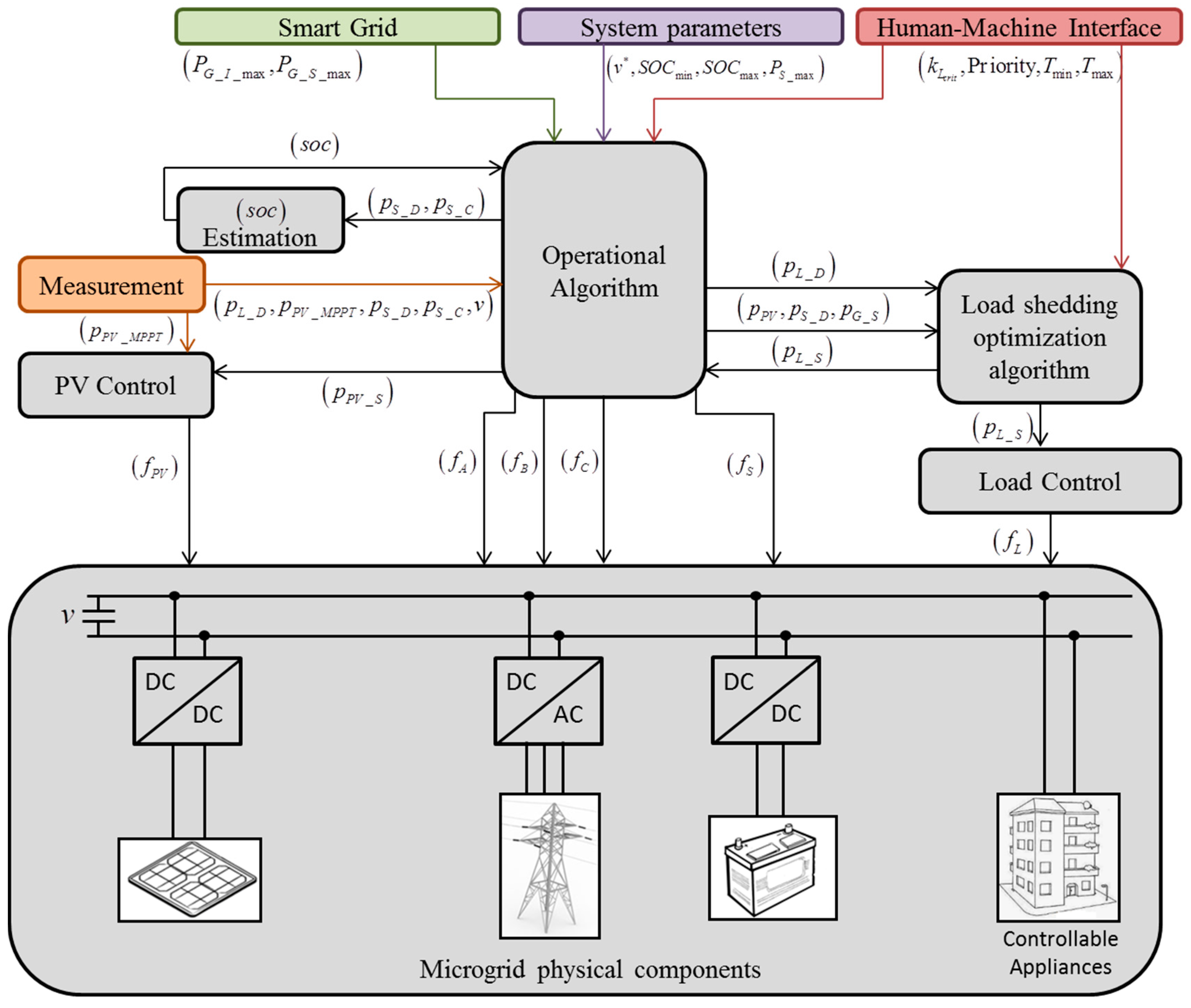
Aiming to interact with the smart grid environment as well as with the end-user, a supervisory system is proposed. The proposed supervisory system is a centralized approach where all of the available data about the microgrid system is concentrated in one main system, as presented in
Figure 3. The power control, represented by the operational algorithm has, as its main goal, to keep the instantaneous power balance in the microgrid system respecting the main grid constraints as well as sources and load constraints.
Figure 3 presents the interconnection between each implemented algorithm necessary to build the described supervisory framework.
The structure presented in
Figure 3 depicts how the information flows from different sources and how it interacts with the proposed algorithms. From the smart grid the information arrives regarding the maximum power allowed to be injected into the main grid,
, and the maximum allowed power to be used from the main grid to supply the microgrid system,
. These limits are supposed to be imposed by the distribution operator system through smart grid messages; they are translated as rigid constraints, meaning that the power exchanged with the main grid can never cross the imposed limits.
The smart grid block emulates the communication layer between the distribution system operator of the main grid and the microgrid system. It is assumed that this communication layer has the capability of sending information about the tariffing system and usage grid limitation to the microgrid as well as receiving back information about the grid usage prediction from the microgrid system.
The system parameters block represents the group of parameters related with the system conception and physical limitations, with being the DC bus voltage reference, and being the maximum instant power allowed to be exchanged with the storage system in both senses.
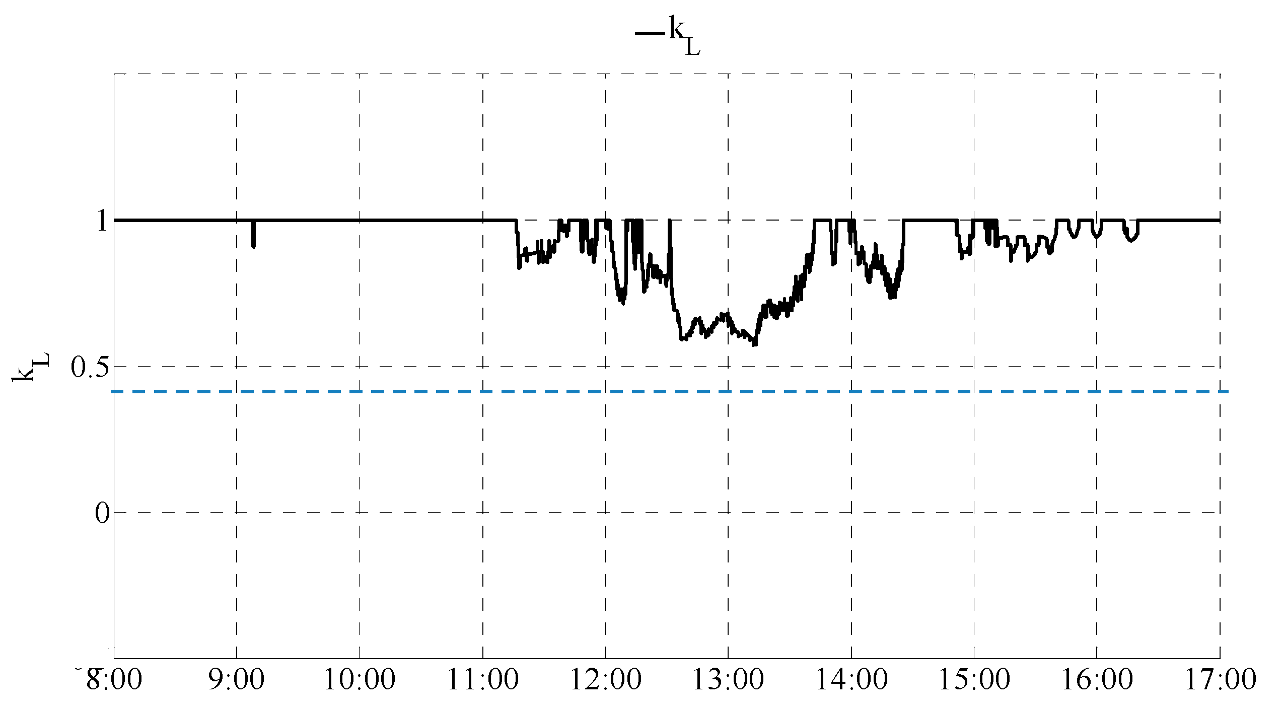
The human-machine interface communicates with both the operational algorithm and the load shedding/restoration algorithm by sending information about the appliances’ priorities and appliance shedding time limits ,. as well as the information about the critical load level .
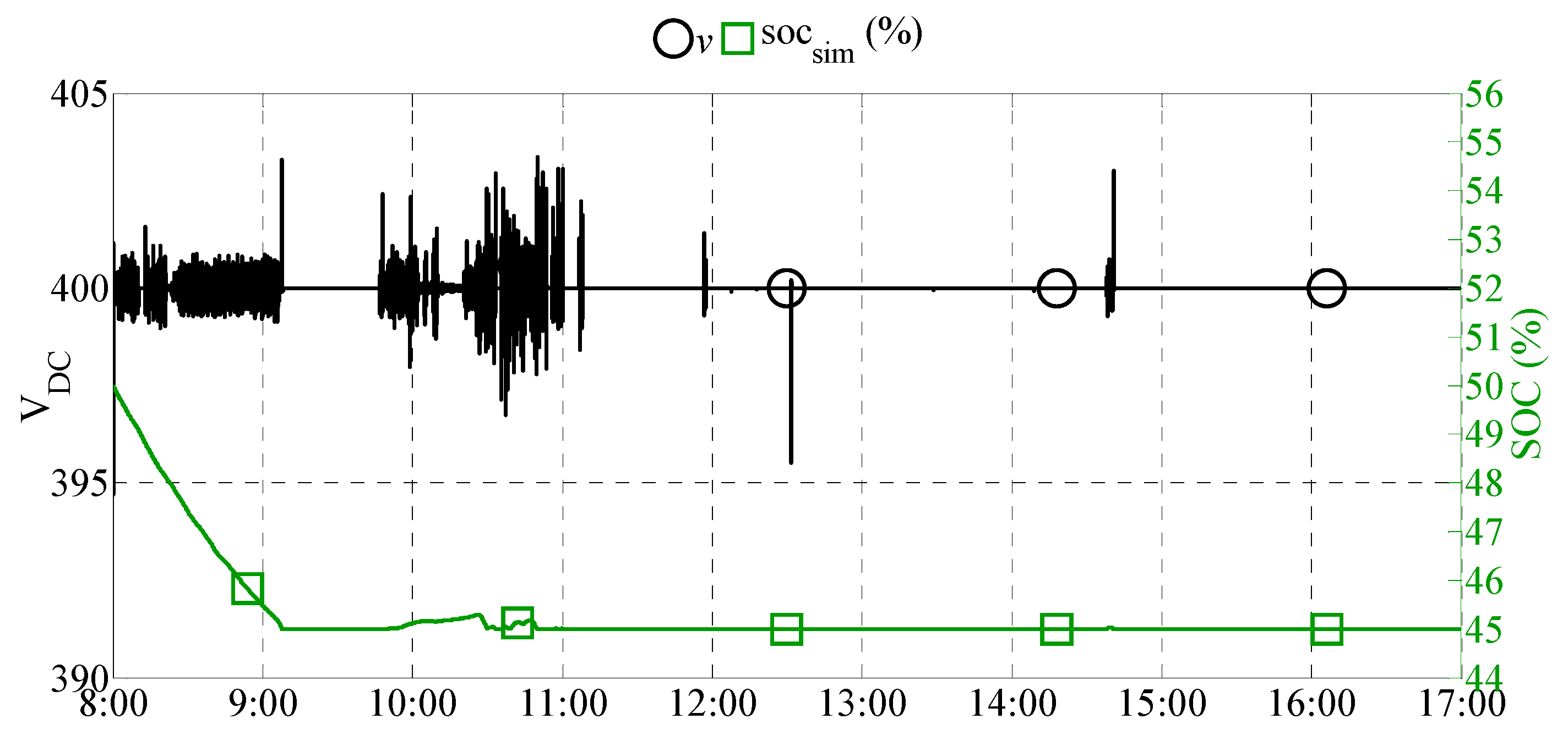
The state of charge (soc) estimation block, using the information about the power exchanged with the storage system , estimates the actual . The energy exchanged with the storage system is limited by the maximum and minimum levels of the calculated state of charge, with and being the minimum and maximum limits of the storage system, respectively. These limits are imposed to increase the lifetime of the storage.
The operational algorithm, responsible for ensuring instant power balance, interacts with the load shedding/restoration optimization algorithm, the PV control, and with all of the physical components through the pulse width modulation (PWM) power converter’s switching functions noted as ,,,,,. The switching functions ,, are related to the three-phase converter at the PCC and are responsible for exchanging power with the main grid. The switching function is sent to the converter responsible for the PV system control. The switching function is related with the converter used for the storage system, and the switching function is a signal with information to be sent to all connected appliances, controlled individually. The load shedding/restoration optimization block receives information about the total load demand and the maximum available power, being the sum of ,, and from the operational algorithm.
The load shedding/restoration block calculates then the optimum load shedding to be sent back to the operational algorithm and to the load control system. The PV control block regulates the PV power to track the maximum power point or the limited power defined by the system given its necessity. The measurement block transmits information about the actual state of the system to the operational algorithm.
2.2. Operational Algorithm
As presented in [
14,
15], to ensure the robustness of the microgrid system it was necessary to separate the real-time control layer from the other layers (e.g., optimization layer). The operational algorithm proposed on this work was based on [
6,
14,
15] and notoriously improved with the capability of dealing, in real-time, with the load shedding/restoration optimization algorithm which consider a real load profile and realistic constraints. The proposed operational algorithm is based on the energy management flowchart presented in [
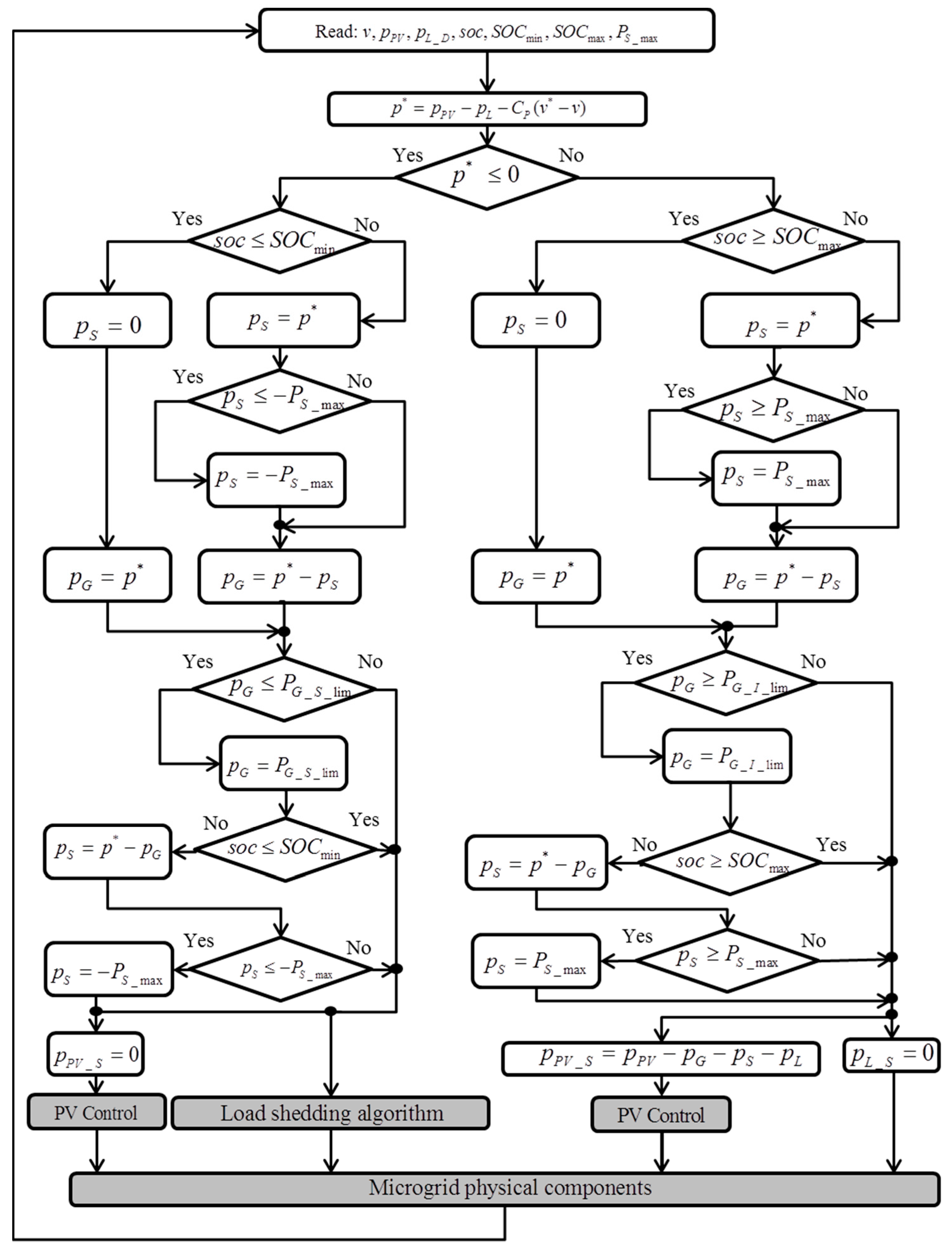
6] and aims to control and ensure power balance in real-time while respecting the storage priority strategy, as well as the imposed system’s limits, as presented in
Figure 4.
At the beginning of each algorithm’s iteration the fixed parameters and the newest values of
,
, and
are set and the reference power,
, is then calculated as presented in Equation (1):
with
being the proportional gain of the controller responsible for the bus voltage stabilization,
the DC bus voltage reference, and
v the real DC bus voltage. This power reference represents the amount of power to be supplied/absorbed to ensure the power balance of the system, and since storage and the main grid can be used to attend this necessity, a storage priority approach was proposed to define this trade-off.
Based on the resulting power reference, the usage of the grid and storage are imposed ensuring power balance while considering the proposed strategy. Based on , the , , and PV power shed and load power shed , are calculated and the real-time PWM control signals, ,,,,, are sent to all dedicated converters.
3. Load Shedding/Restoration Optimization Algorithm
In the case where the PV production is too low or nonexistent, and the maximum allowed power to be exchanged with the storage and the main grid is already reached, but still the system would not be able to stabilize the DC bus voltage, load shedding occurs following a predefined strategy.
On the other hand, to supply the critical load limit is a necessity for commercial and industrial environments. To ensure keeping critical equipment and services operating under any circumstances, i.e., respecting the critical level imposed by the end-user, it is necessary to consider the limit imposed to the power exchanged with the main grid at least equal to the power required to supply the critical loads of the system. Otherwise, the microgrid system has to include a traditional energy source, like a micro-turbine or a diesel generator, which is necessary to start up in critical operating conditions. The proposed scenario considers a correctly-sized main grid power supply limit able to always ensure the critical load level and to perform demand-side management, based on the optimized load shedding and restoration approach.
When the microgrid is operating in limited mode, meaning that the available power from all sources is not enough to attend the load power demand, the load shedding must be used to keep the power balance and voltage stabilization. In this work the proposed load shedding method aims to be more realistic by considering each appliance with a discrete value and using an approach based on the knapsack problem to formulate the load shedding optimization problem. The proposed approach is described in detail in [
17], where the main problem to be solved is to know what appliance can operate and what appliance needs to be turned off, considering a group of constraints related with the maximum time that each appliance can be shed, as well as the priority of each appliance. In this paper, the proposed load shedding/restoration approach is proposed to a DC microgrid system but this concept can be extrapolated to any microgrid architecture one could desire.
3.1. Knapsack Problem
The knapsack problem relative to load shedding/restoration cases is formulated following [
18] and strongly improved concerning the appliances’ restoration conditions. It can be expressed as described in Equation (2):
with
being the objective function,
is the coefficient of priority of
ith appliance,
i is the appliance identification number,
is the decision variable of the load shedding algorithm optimization,
is the instant power of
ith appliance,
is the coefficient of original priority of the
ith appliance,
is the time duration for which the appliance is shed,
is the time duration for which the appliance is in on-state mode,
is the maximum time duration for which the appliance can be shed, and
is the minimum time duration for which the appliance can be shed.
The definition of minimum and maximum values to the timers tied with the restoration aspect of the load control is fundamental to implement a realistic load shedding/restoration process. On one hand, these timers are vital to ensuring the smart use of the load shedding algorithm, allowing the system to reduce the impact of continuous shedding of a single appliance to the end user. On the another hand, these timers also provide a certain level of safety to the appliances, ensuring to avoid flickering a rapid and continuous connection and disconnection of energy supply, unsafe to appliances in general, but especially harmful to electronic devices. For these reasons, approaching the load shedding/restoration problem only from the point of view of the load shedding itself, without considering the restoration aspects, it is simply not enough in a realistic load shedding/restoration approach.
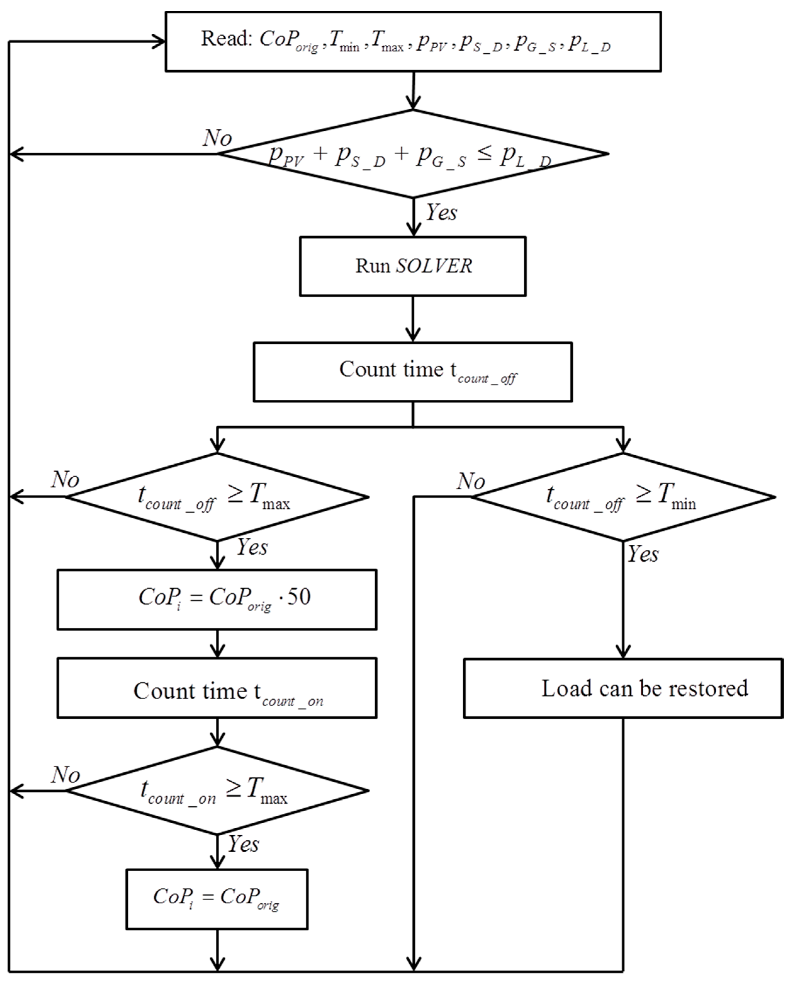
3.2. Load Shedding/Restoration Optimization Operation
The load shedding/restoration algorithm operates following the scheme presented in
Figure 5. At the beginning, the inputs of the coefficient of priority, the minimum and maximum time, the available power, and the power demand are read and a decision is made. If the power demand is less than the power available, the algorithm does not perform the load shedding. Otherwise, when the power available is insufficient to attend the load power demand, the solver is called to perform the load shed optimization. The problem is solved by mixed integer linear programming and the CPLEX solver.
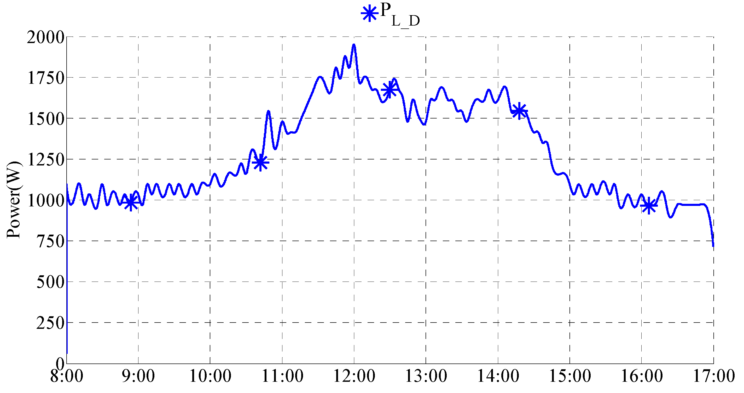
3.3. Building Load Profile Sample
The building load profile is presented in
Figure 6, with
being the power load demand for the given day. This profile, detailed in
Table 1, is based on the historical data of the building
Pierre Guillaumat 2 from the Université de Technologie de Compiègne, France. The number of appliances and rated power were adapted to fit the physical restriction of an existing microgrid platform [
2]. The designed scenario, where all appliances are fully controllable was selected to highlight the impact of considering demand-side management based on a load shedding approach in the microgrid system environment. Although a realistic scenario will have only a few controllable appliances, this will not change the concept proposed in this paper since all non-controllable loads would be considered as critical loads. This adaptation aims to allow us to validate in simulation, respecting the real dynamic of the building with the proposed load shedding approach. To perform an experimental validation it would be necessary for a load emulator to be able to control each appliance independently and, for instance, this equipment is not yet available in our microgrid platform.
The load profile considers the load power demand from 8:00–17:00, defined as a 9 h day during commercial time. After this time, from 17:00–8:00 the next morning, the main grid is assumed to supply the minimum energy consumption.
It is considered that the power required to supply the maximum part of building load power is limited to 2000 W, given the physical constraints of the system. To respect this limit, the number of appliances considered to form the load profile sample presented in
Figure 6 is limited to 49 different appliances, selected in such a way that the general load dynamic during the day remains the same as the real original load of the building.
Table 1 shows the appliances’ specifications: identification number
i, coefficient of original priority
, the nominal power
of the
ith appliance, and time duration
and
to some of the 49 appliances.
5. Conclusions
First and foremost, the microgrid system is an answer to the necessity of increasing the renewable energy penetration in a sustainable way to maximize the use of renewable energies, and reducing the consumption of fossil fuels and other non-renewable sources. When it comes to commercial building applications, some of the challenges were addressed in this paper, such as ensuring voltage stabilization and increasing reliability by actively ensuring power balance. Compared with the literature and previous works, the improvement comes from a demand-side management strategy. This strategy was proposed based on a critical load limit and on a load shedding/restoration optimization algorithm ensured during operation. In addition, the proposed strategy was validated through simulation tests and is based on a realistic load curve, which was built based on real building consumption. Furthermore, the supervisory controller can be further elaborated either by programming a digital signal processor (DSP) with the C programming language, or by programming a controller based on field programmable gate arrays (FPGA) (e.g., Xilinx ISE), so that it can have applications in the industrial field. In the environments where DC loads are becoming predominant, the usage of a DC microgrid architecture can improve the overall efficiency of the system, avoiding a waste of energy in the consecutive transformation from DC to AC and back to DC, before finally being consumed by the load. The whole microgrid architecture described on this paper was designed to create a flexible system. This approach, when applied in a commercial building or industry, allows the user to have the best trade-off between reducing the energy cost, ensuring voltage stabilization, increasing robustness, and maximizing renewable energy penetration, while respecting the main grid limitations and allowing the system operator to act more efficiently without stopping any critical operations on site. This flexible system goal is achieved by the integration of different algorithms interacting based on a management system that handles the dichotomy between the different approaches and the instant power balance. In future works, to obtain the most of this flexibility, different approaches for the management strategy shall be implemented, based on optimization methods, aiming to decrease the energy cost to the end user.


