Experimental In-Plane Evaluation of Light Timber Walls Panels

Institute for Sustainability and Innovation in Structural Engineering, Civil Engineering Department, University of Minho, Guimarães, 4800-058, Portugal
*
Author to whom correspondence should be addressed.
Buildings 2017, 7(3), 63; https://doi.org/10.3390/buildings7030063
Submission received: 27 March 2017
/
Revised: 6 July 2017
/
Accepted: 6 July 2017
/
Published: 13 July 2017
(This article belongs to the Special Issue Seismic Performance of Timber Platform Frame Buildings)
Abstract
:In general, the satisfactory seismic performance of timber buildings can be partially attributed to the material characteristics of the wood itself and to the lightness of its own structure. The aim of this paper is to analyze the in-plane behavior of light timber walls panels through a series of monotonic and cyclic tests, and to evaluate how the sheathing material and the fixation to the base influence the overall response of the wall. Five tests are presented and discussed while the reliability of an analytical method to predict the response of the walls is studied. The sheathing material revealed to be important in the overall response of the wall. Moreover, the type of fixation to the base also revealed to be important in the in-plane response of timber walls. In-plane stiffnesses, static ductility, energy dissipation and damping ratio have been quantified.
1. Introduction
The development of engineered wood products and improved techniques for timber constructions, together with the shift to performance-based design, has created a renewed interest in timber construction systems, particularly in medium- and high-rise construction. Current building codes for timber structures seem to be underdeveloped when compared with those of concrete, steel, and masonry. Hence, it is of prime importance to identify the research needs for wood buildings and to establish a firm scientific basis for their codes and regulations. Presently, much of the research work aims at studying the possibilities of modern timber solutions in housing. Modern timber constructions exhibit good fire performance, acoustic behavior, improved strength and durability. However, a lot of their aspects are unexplored. This work intends to increase the working knowledge on the seismic performance of timber structures [1,2,3] when subjected to seismic actions.
Timber-frame structures have been known to exist for centuries. Up until the 19th century, in log-house buildings a heavy framing post and beam system was used. However, when it was found that the structure was stable without heavy structures, the technique of light-frame wooden construction was developed. The balloon framing system was used between the 19th and 20th centuries. It was characterized by a single beam running from the bottom floor to the top. The wooden members were more slender than those used in the post and beam system and the need for complicated carpentry joints was eliminated. The balloon framing system finally gave way to the platform frame system, which is the only framing system currently used. These structures use shorter lengths of lumber and have a much faster speed of construction. Large areas could be enclosed with minimal cost compared to previous framing techniques [4].
Contrary to what would be expected, light frame structures are not weaker than heavy timber-braced frames [5]. In the platform frame system, as the name suggests, each story is erected on top of the platform of the preceding floor or, in the case of the ground floor, on the building’s foundations. Thus, the floor below becomes the working platform for the one above. As the construction work proceeds, the bracing of the building’s timber frame functions as a platform on which walls and internal partitions of the subsequent floor are constructed [6]. It is estimated that across all the developed countries, timber frame accounts for around 70% of all housing stock, representing some 150 million homes [7].
In light frame constructions, the seismic forces and wind forces acting on the superstructure are transferred to the foundation via shear walls and floor/ceiling assemblies that act as diaphragms. The repetitive wood framing members sheathed with plywood or OSB (Oriented Strand Board) wood structural panels maintain high stiffness and strength in the design range until they reach their ultimate capacity, at which point they begin to yield gradually while continuing to carry high loads and absorbing a lot of energy before failure. For multistory light-frame timber buildings, the preferred failure is of the nailed/screwed connections between the sheathing and the frame, as it is highly ductile.
As part of the feasibility studies of multistory light-frame timber buildings, research efforts focusing on the seismic design aspect were responsible for the shift to performance-based design (PBD) of these structures. This shift entails accurate models of wood-frame buildings under seismic loading that need to be developed. For this to happen, a fully mechanistic or constitutive understanding of the individual components, sub-assemblies, and their interaction to form a complex structural system is required. In the last few years, various experimental research has been conducted to assess the behavior of different timber-based systems under in-plane horizontal loads [8,9,10,11], and through full-scale shaking tests following different peak acceleration values [3,12,13,14,15,16]. Those experiments have been crucial for the development of different analytical and numerical models to represent the response of different timber-framed walls and buildings [17,18,19,20], making it possible to enlarge the value of the findings through different parametric studies [21,22]. In the particular case of light-frame shear walls, past research has shown that the sheathing material [23,24,25,26] and the type of fixation to the base used are important variables in the local and overall behavior of such systems under lateral in-plane loads. It is expected that with the presence of the sheathing material and its stiffness, the load-carrying capacity and the stiffness under in-plane horizontal loads will increase. Additionally, the stiffness of the fixation to the base of the timber-frame walls plays an important role. With a high stiffness, the sliding movement of the wall under lateral loading is then substituted by rocking. Despite this evidence, there is a lack of studies about the influence of the sheathing material and on the type of fixation to the base. In fact, some variability can happen on-site with the sheathing material. For example, the use in only one side for construction reasons (technical openings, the use of thin gypsum, etc.) with unknown consequences on the light timber-frame wall response. The same questions arise with the type of fixation to the base. Different types of connectors can be used, with distinct levels of technical information available depending on the brand or manufacturer, but in some cases, the old steel rod is used to fix the timber-frame wall to the base. It is clear that more studies are needed to support the decisions of the builder and of the designer.
In this context, and within a process of development of a light-timber panel, an experimental program was planned to evaluate different light-timber frame walls, assessing the influence of the presence of the sheathing material and type of fixation to the base. The aim of this experimental program was to assess the influence of those variables in the design of the panel and, therefore, to evaluate the need and the importance of each element (sheathing element and fixation to the base) in the overall behavior of the panel under development.
2. Experimental Program
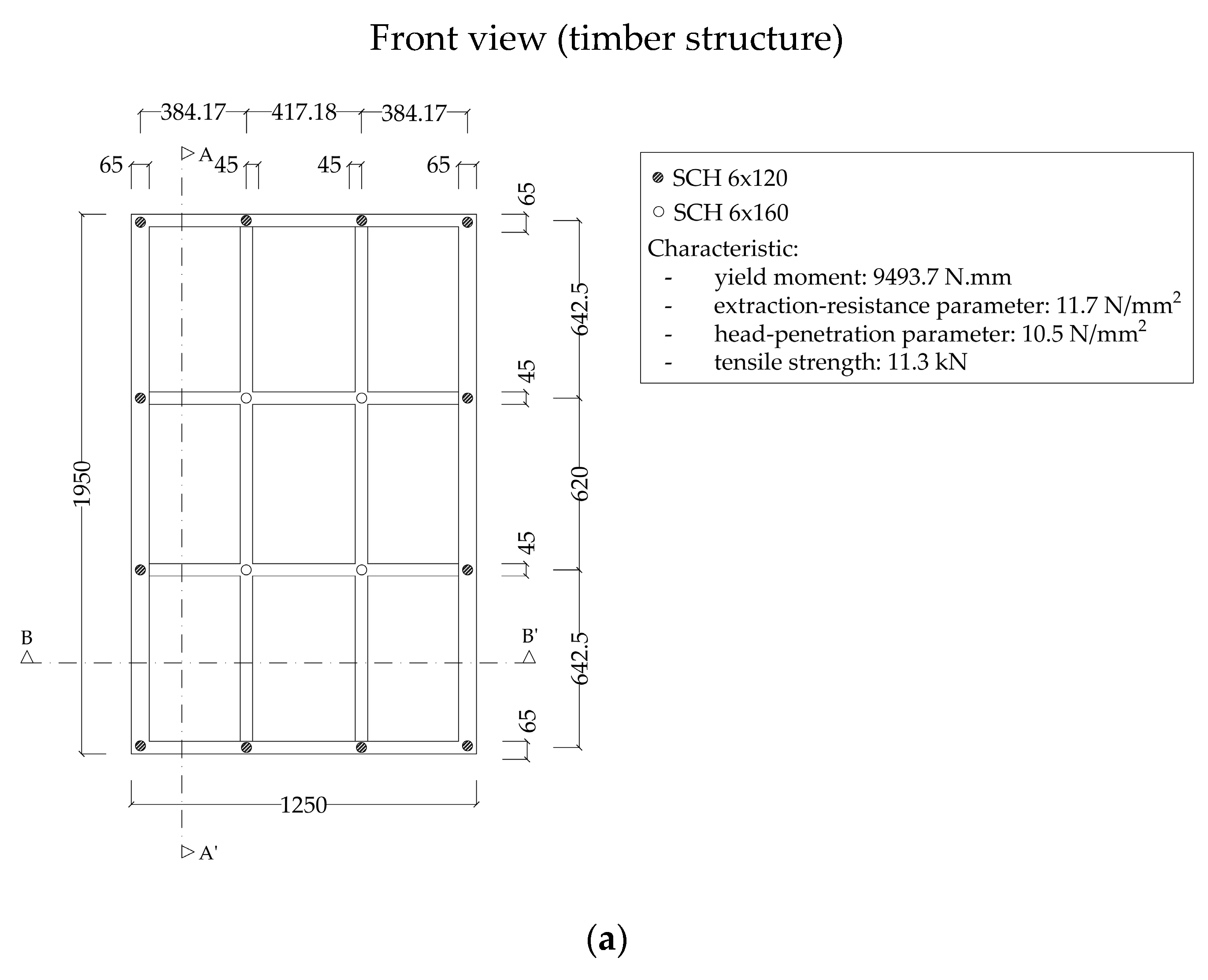
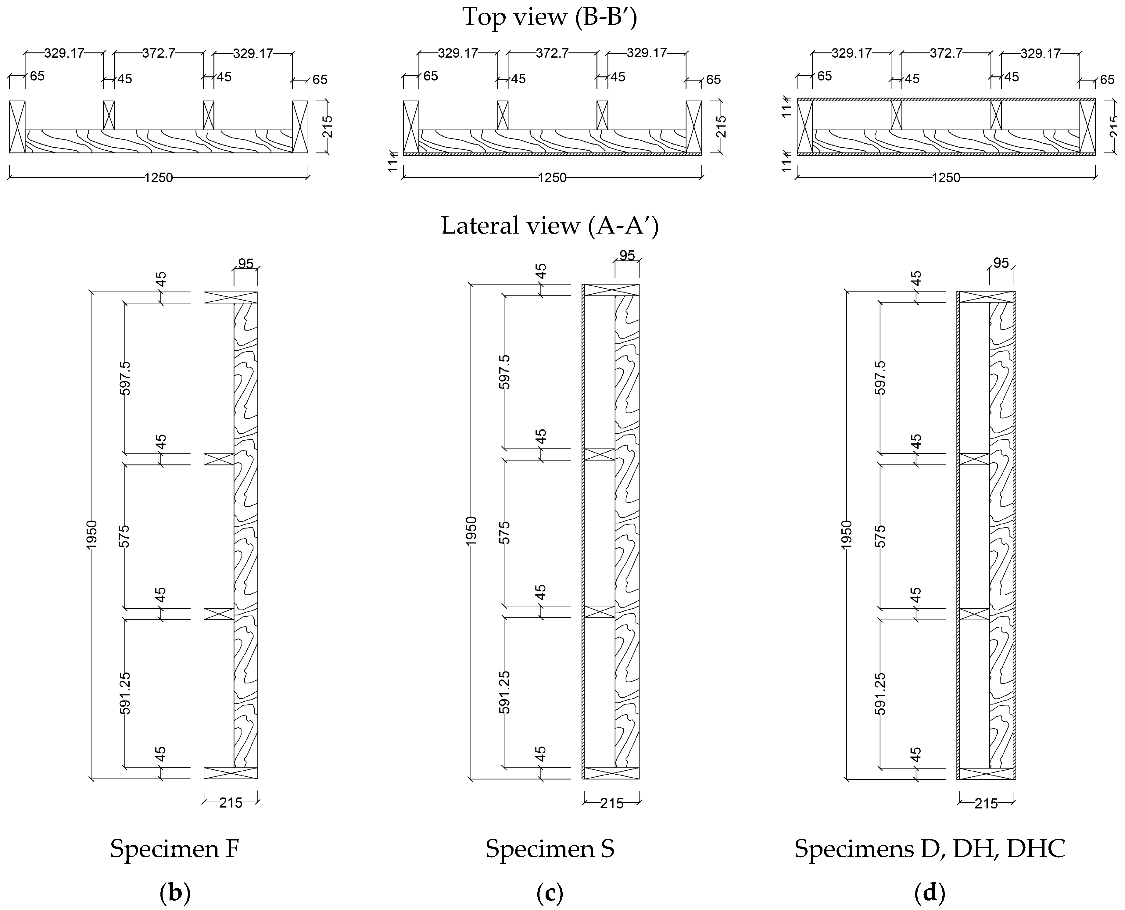
As mentioned, within the process of development and characterization of a new kind of prefabricated timber panel, an experimental program composed of five tests on single timber panel walls has been carried out. This experimental campaign comprised four tests under monotonic loading and one with the application of cyclic loading. Different sheathing layouts were studied and distinct fixation solutions to the base were evaluated. All panels used presented the same internal structure, 1250 mm by 1950 mm (see Figure 1a), composed by two longitudinal elements of 65 mm × 215 mm and two transversal ones (one on the top and another at the bottom) of 45 mm × 215 mm. Inside this external frame, an internal grid is made by means of two transversal elements of 45 mm × 120 mm and two longitudinal elements of 45 mm × 95 mm. All elements are screwed with SCH RothoBlass® screws of 6 mm, their length being 120 mm or 160 mm if placed in the internal grid or in the external frame, respectively. The first specimen evaluated (F) consists in this timber structure without any kind of sheathing and fixed to a concrete base with steel rods (see Figure 1b). Then, the second specimen considered (S) had an 11 mm OSB panel in one side (see Figure 1c). The third (D) had one 11 mm OSB panel in each side of the structure (see Figure 1d). Both specimens kept the same fixation to the base through steel rods. The fourth specimen (DH) was similar to the third (see Figure 1d), the timber frame structure sheathed in both sides by an 11 mm OSB panel, but now two HTT22 hold-downs from Simpson Strong Tie were used to fix the panel to the base. Finally, the fifth specimen (DHC) was equal to the fourth (see Figure 1d) and was tested under a cyclic loading. Table 1 presents a summary of the test program that was undertaken, with a description of each specimen, the fixation to the base used and the loading protocol applied, while Figure 1 presents the specimens and their main details.
The internal timber structure of all panels was composed by elements of C24 strength class according to EN 338. The OSB used as sheathing elements was fixed to the internal timber structure using 3.5 mm × 35 mm screws and polyurethane glue for timber.
2.1. Test Procedures
Two types of loading procedures have been applied: monotonic and cyclic. Through the monotonic test, it is possible to assess the maximum force (Fmax), the elastic stiffness, the elastic and ultimate displacement and the ductility. On the other hand, cyclic tests are important because they allow a clear view of the ability of the panel to dissipate energy and the behavior of the panel after the maximum load. The definition of the cyclic loading procedure is defined based on the elastic displacement, quantified through a monotonic test. The differences between the tests procedures was limited to the loading protocol applied, given that the setup and the instrumentation kept constant.
2.1.1. Monotonic Test (Static)
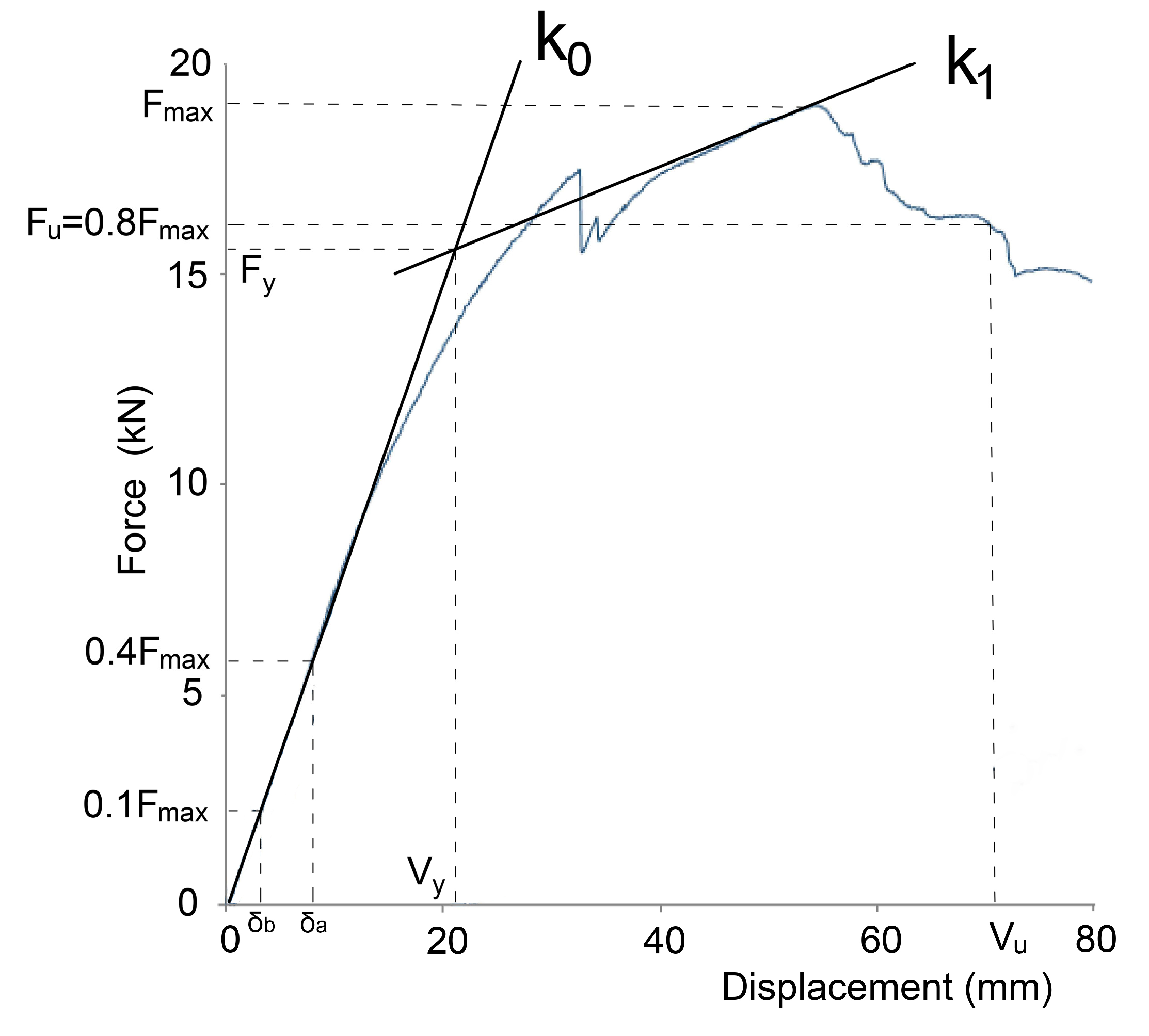
The monotonic test consisted on the application of a displacement under a constant rate on the top of the specimen. The displacement was applied under a rate of 0.15 mm/s, in accordance with the EN 12512 [27]. For the quantification of the elastic stiffness, two methods have been applied. In the method proposed by EN 12512 [27], the initial stiffness k0 and km are quantified through slope of the trend line of the force-displacement curve between 10% and 40% and the slope of the tangent line of the first linear part, respectively, and the post-elastic stiffness k1 is quantified through 1/6 of the initial stiffness (k0). Adopting the method suggested by the ISO/FDIS 21581 [28], the elastic stiffness is given by:
where δa and δb are the displacements of the 40% and 10% of the maximum force, respectively.
In relation to the values of the elastic (Vy) and the ultimate (Vu) displacements, they are quantified as depicted in Figure 2. Vy was quantified through the intersection of the lines k0 and k1, while Vu is defined by the displacement value corresponding to 80% of the maximum force. Finally, the static ductility (D) has been quantified as defined by the EN 12512 [27], given by the ratio between the ultimate value (Vu) and the elastic value (Vy) of the displacement.
2.1.2. Cyclic Test (Static)
The cyclic test performed (DHC) consisted in a standardized quasi-static cyclic loading procedure (see Figure 3) defined based on the EN 12512 [27], after the definition of the elastic displacement (Vy) obtained through the corresponding monotonic test (DH).
Using the obtained load-displacement curves, it is then possible to quantify the following quantities of interest:
- (a)
- the strength reduction for each set of three cycles at each tested ductility level, both in tension and compression;
- (b)
- the damping ratio at each tested ductility level, evaluated from the third cycle of each set of three cycles. The equivalent viscous damping ratio is defined as , where Ed is the energy dissipated per half cycle and the Ep is the available potential energy;
- (c)
- the maximum ductility level reached, referring to the envelop load slip curve of the first cycle of each set of three cycles at each tested ductility level, both in compression and tension.
2.2. Tests Setup
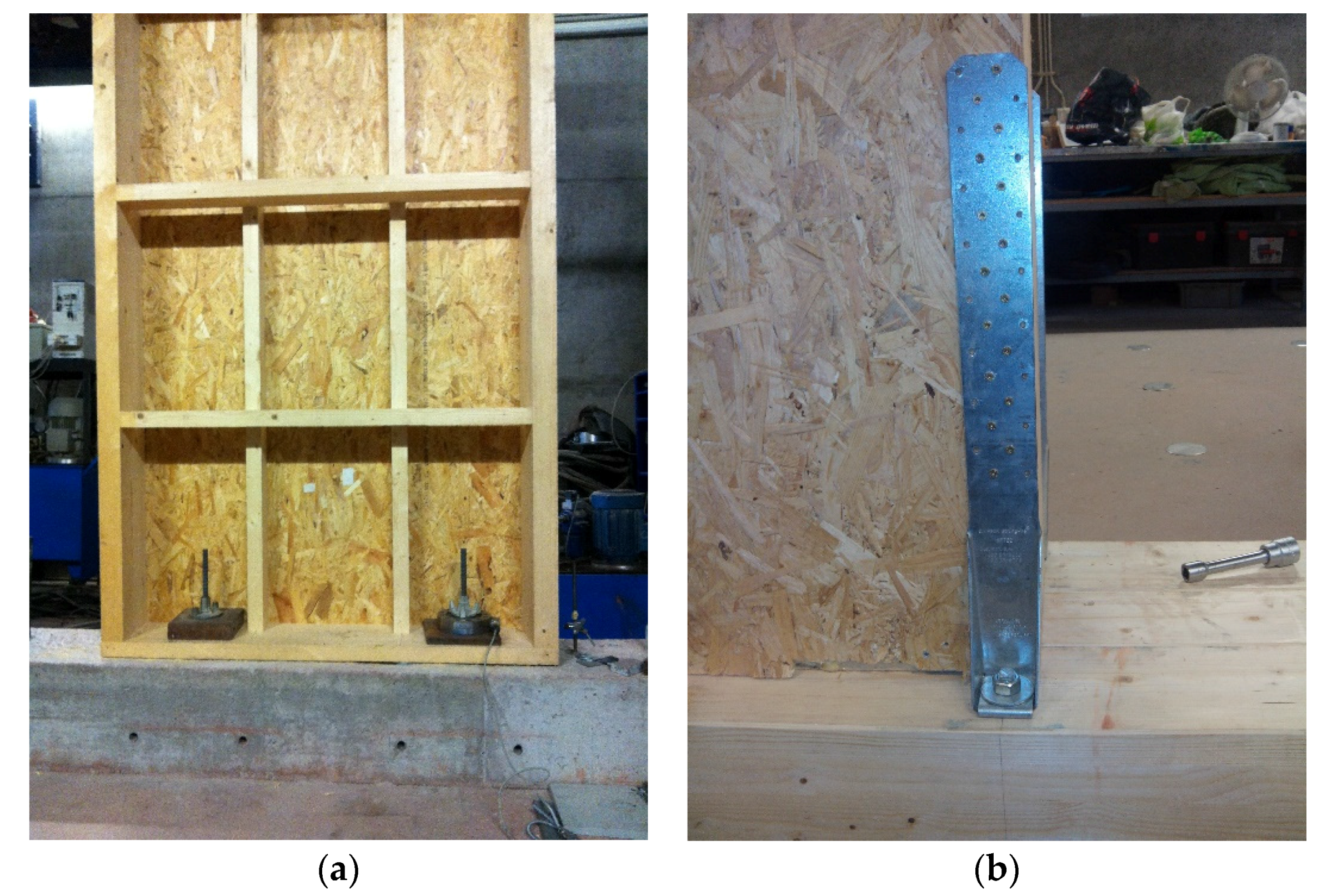
The test setup used is depicted in Figure 4 and tries to simulate the real behaviour of timber panels, paying special attention to the their fixation to the base (see Figure 5).
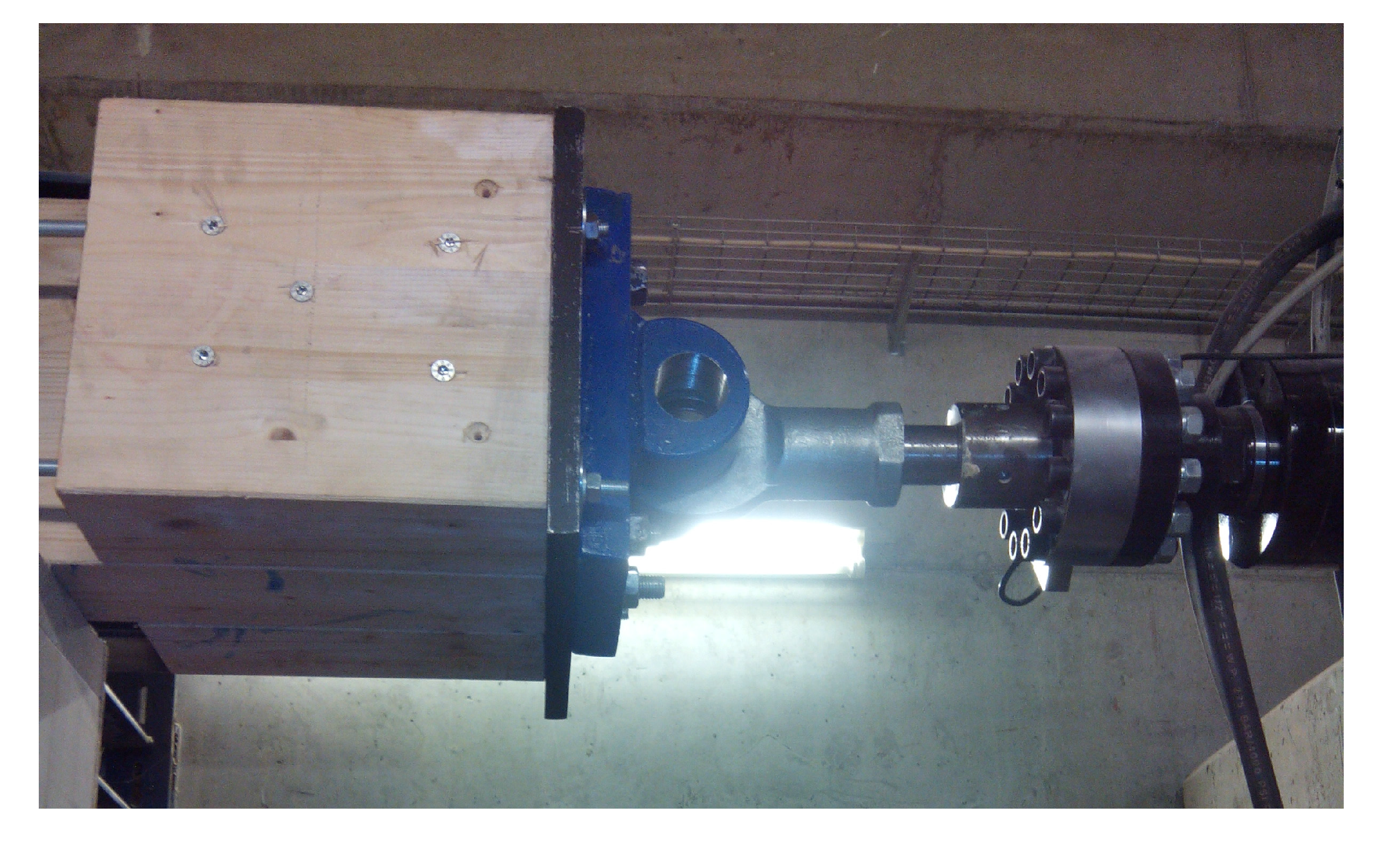
The loading procedure was applied to specimens through a timber beam fixated on the top (see Figure 6), so as to ensure a uniform distribution of the lateral loads originated by the displacement defined by the loading protocol. Attached to this top beam, a load cell with a maximum capacity of 500 kN was responsible for the applied compression and tension effects induced by the loading procedure.
3. Results
The main results obtained from the experimental program are described and discussed. Five specimens were tested, four under monotonic loading and one with cyclic loading, and the results were separated in two groups. With the first group (specimens F, S and D), the influence of OSB boards on shear walls on monotonic tests was evaluated and, with the other group (Specimens DH and DHC), the mechanical properties between the cyclic and monotonic test was evaluated. To describe the in-plane behavior of the panels evaluated, the stiffness, ductility, impairment of strength and energy dissipation were quantified and the values obtained have been discussed.
3.1. Specimens F, S and D
Specimen F consists of the internal timber structure of the panel, without any kind of sheathing element, and specimens S and D are identical but for the addition of the sheathing element (11 mm OSB) on just one side and both sides, respectively.
The analysis of the graph of Figure 8 shows that, as expected, the specimen F presents a very low in-plane stiffness and a reduced load-carrying capacity, contrary to specimens S and D, for which the presence of OSB boards increased the in-plane stiffness and load-carrying capacity. Moreover, it is verified that displacement relative to maximum force of the specimen S occurred in 48.1 mm and the specimen D in 54.4 mm. Despite the increase of resistance, the rocking does not exist because the values are very low. However, the failure of the samples occurred on the pullout of the screws (tensile tensions) on the bottom right corner (Figure 9 and Figure 10).
3.2. Specimens DH and DHC
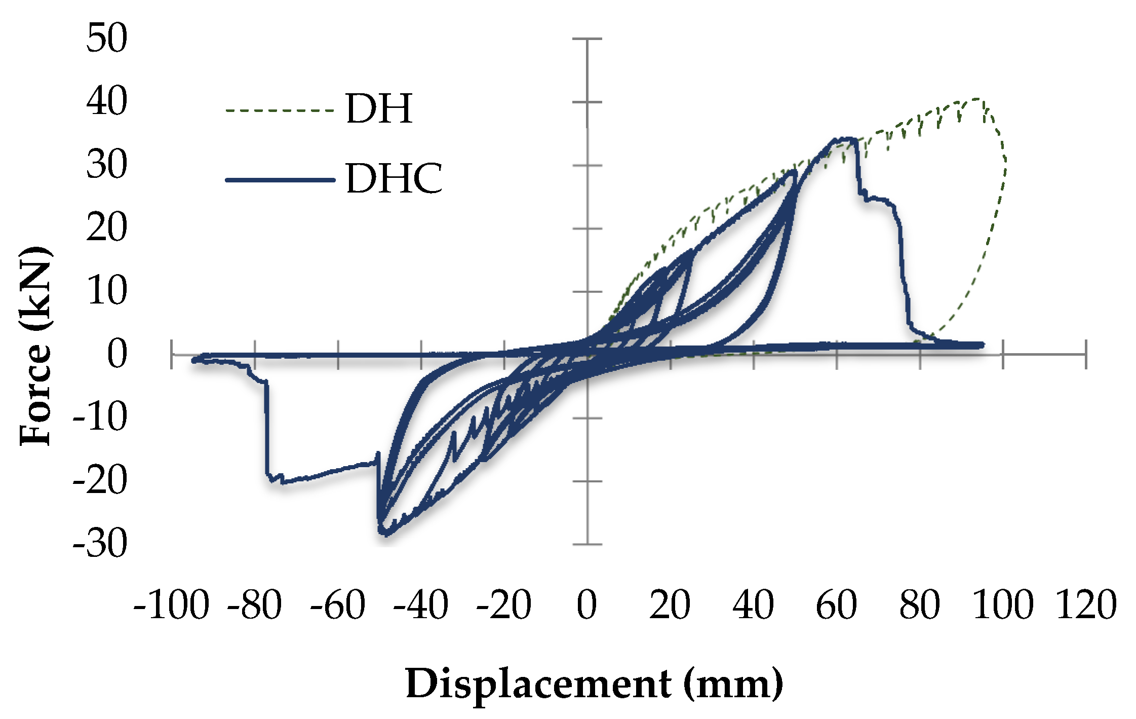
Specimens DH and DHC are similar to specimen D, but now hold-downs were used to fix the panel to the base (timber). The cyclic loading of specimen DHC procedure was defined in accordance with EN 12512 [27] and by using the elastic displacement value obtained from the DH test, as both specimens are identical, with the loading protocol as the only difference. Figure 11 shows the experimental force-displacement loops obtained during the DHC test and the DH monotonic test.
The analysis of the graph shows the decrease of the load-carrying capacity of the cyclic test around 28% in comparison with the monotonic test. Therefore, the failure of specimen DHC happened on the expected area, on the pull out of the screw in the hold-down connection between the timber base and the connector (hold-down), located on the bottom right corner, and the failure of the DH, as it did in the previous specimens, in the connection between the vertical profile and the lower horizontal profile.
By analyzing just the experimental force-displacement loops, the high ductility already evidenced by the similar monotonic test (specimen DH) is confirmed. In accordance with Table 2, it is important to point out that the impairment strength (ΔF) measured for each cycle range is consistent, showing an insignificant difference between the values observed in compression and in tension. The higher value obtained for the impairment strength, as expected, corresponds to the last cyclic range, equal to 16%.
4. Discussion of the Tests Results
Table 3 presents the comparison of the mechanical properties obtained in the five specimens tested (F, S, D, DH, and DHC). It is clear the substantial increment of the in-plane stiffness given by the sheathing material when the stiffness of the specimen F is comparable to the other ones. Moreover, the increase of in-plane stiffness is proportional to the number of sheathing elements. When two OSB sheathing elements are used (D), the stiffness is nearly double of the one obtained with one OSB sheathing element (S). On the other hand, the type of fixation to the base is also important. Using the hold-downs (specimen DH), in direct comparison with specimen D, the load-carrying capacity of the panel doubles (increases from 19.03 to 40.50 kN) and the in-plane stiffness increases around 23%.
A comparison between the specimen DH and DHC demonstrates the decrease of the resistance in relation to the cyclic test (DHC). This decrease can be said to be normal by reason of the cyclic test is more aggressive to the structure, in which there occurred a decrease in maximum force (around 15%), stiffness (around 28%) and ductility (around 54%).
5. Analytical Model
As mentioned before, there are some analytical methods that can be compared with the experimental tests in the evaluation of the in-plane stiffness of timber walls. Among the different analytical methods available, it has been decided to apply the one developed by Casagrande et al. [22] based on cyclic tests on full-scale timber walls. For that purpose, the results of test with the DH specimen were used.
In accordance to this analytical method, to quantify the elastic displacement (Δ) for certain forces Equation (2) should be applied, while Equation (3) allows to quantify the stiffness (ktot) of the wall. It should be noted that Equation (3) is only valid when the vertical load (q) is zero or when the hold-down is in tension, as it is in the analyzed case.
where:
- −
- F is the force applied;
- −
- is the sheathing-to-framing connection stiffness
- −
- is the sheathing panel shear stiffness, KA is the rigid body translation stiffness;
- −
- is the rigid body translation stiffness;
- −
- is the rigid body rotation stiffness;
- −
- and N is half part of the vertical load (in this case, N = 0).
The analytical method was applied considering the geometrical and mechanical properties resumed in Table 4.
Table 5 and Table 6 present the comparison between the experimental values obtained for the displacement and in-plane stiffness, and the values predicted by the analytical method proposed by [22]. The value of error was added as a complement to these data, in which it was calculated by the difference between the analytical and experimental data divided per experimental value. Therefore, a significant difference between the analytical and the tests results can be pointed out (the error values obtained are around 24%). However, it is important to point out that the DH specimen analyzed here did not use angle brackets to connect the wall to the base, while all specimens used to develop the analytical method proposed by [22] were fixed to the base with both hold-downs and angle brackets.
6. Conclusions
After the tests of the walls and the analysis of the results it can be concluded that this type of panel system presents good mechanical characteristics when used as a wall panel. Several configurations of the panel were analyzed in order to evaluate the response of the panel in the face of possible changes, namely its coating.
It is concluded that the wall panel consisting solely of the timber profiles shows low stiffness in the plane when a horizontal force is applied. However, and as expected, when the OSB board is added the stiffness increases considerably. The stiffness almost doubles in relation to one side with OSB board to both sides with OSB boards.
It was also observed that the force-displacement behavior and the energy absorption characteristic of the cutting walls are influenced mainly by the characteristics of the connections.
As the main conclusion, it can be affirmed that this type of panel works well as a modular wall panel, in that it must have at least one fastening plate, namely an OSB board, giving it the rigidity necessary to cope with the horizontal loads. Moreover, this material offers good ratio of weight resistance, it has high durability, high stiffness and resistance to deformation, rupture, and delamination, with a reduced environmental impact. However, the side of the panel that will be inside the housing can be filled with a closing panel to the customer’s taste, the same panel functioning as the final coating.
Author Contributions
J.M.B. and P.B.L. conceived the experimental work and performed it. F.T.M. analyzed the data and applied the numerical model. The paper was written by all the three authors.
Conflicts of Interest
The authors declare no conflict of interest
References
- Bedon, C.; Fragiacomo, M.; Amadio, C.; Sadoch, C. Experimental study and numerical investigation of Blockhaus shear walls subjected to in-plane seismic loads. J. Struct. Eng. 2015, 141, 04014118. [Google Scholar] [CrossRef]
- Ceccotti, A.S.C.; Okabe, M.; Yasumura, M.; Minowa, C.; Kawai, N. SOFIE project—3D shaking table test on a seven-storey full-scale cross-laminated building. Earthq. Eng. Struct. Dyn. 2013, 42, 2003–2021. [Google Scholar] [CrossRef]
- Van de Lindt, J.W.; Pei, S.; Pryor, S.E. Construction and experimental seismic performance of a sull-scale six-story light-frame wood building. Procedia Eng. 2011, 14, 1599–1605. [Google Scholar] [CrossRef]
- Lim, E. A Brief History of Wood-Frame Construction. Available online: http://www.gather.com/viewArticle.action?articleId=281474979249500 (accessed on 22 March 2017).
- Langenbach, R. Resisting Earth’s forces: Typologies of timber buildings in history. Struct. Eng. Int. 2008, 18, 137–140. [Google Scholar] [CrossRef]
- Department of the Environment. Community and Local Government, Ireland. Building Standards—Current Practice and Procedures. 2007. Available online: http://www.environ.ie/en/Publications/DevelopmentandHousing/BuildingStandards/FileDownLoad,1671,en.pdf (accessed on 22 March 2017).
- Hastoe Housing Association. Sustainable Homes: Timber Frame Housing. 2000. Available online: http://www.sustainablehomes.co.uk/Portals/63188/docs/Timber%20Frame%20Housing.pdf (accessed on 27 March 2017).
- Vieux-Champagne, F.; Sieffert, Y.; Grange, S.; Polastri, A.; Ceccotti, A.; Daudeville, L. Experimental analysis of seismic resistance of timber-framed structures with stones and earth infill. Eng. Struct. 2014, 69, 102. [Google Scholar] [CrossRef]
- Poletti, E.; Vasconcelos, G. Seismic behaviour of traditional timber frame walls: Experimental results on unreinforced walls. Bull. Earthq. Eng. 2014. [Google Scholar] [CrossRef]
- Sartori, T.; Piazza, M.; Tomasi, R.; Grossi, P. Characterization of the mechanical behaviour of light-frame timber shear walls through full-scale tests. In Proceedings of the World Conference on Timber Engineering (WCTE 2012), Auckland, New Zealand, 15–19 July 2012; Volume 3. [Google Scholar]
- Vogt, T.; Hummel, J.; Seim, W. Timber framed wall elements under cyclic loading. In Proceedings of the World Conference on Timber Engineering (WCTE 2012), Auckland, New Zealand, 15–19 July 2012. [Google Scholar]
- Van de Lindt, J.W.; Pei, S.; Pryor, S.E.; Shimizu, H.; Isoda, H. Experimental seismic response of a full-scale six-story light-frame wood building. J. Struct. Eng. 2010, 136, 1262–1272. [Google Scholar] [CrossRef]
- Steiger, R.; Feltrin, G.; Weber, F.; Nerbano, S.; Motavalli, M. Experimental modal analysis of a multi-storey light-frame timber building. Bull. Earthq. Eng. 2015. [Google Scholar] [CrossRef]
- Songlai, C.; Chengmou, F.; Jinglong, P. Experimental study on full-scale light frame wood house under lateral load. J. Struct. Eng. 2010, 136, 805. [Google Scholar] [CrossRef]
- Germano, F.; Metelli, G.; Giuriani, E. Experimental results on the role of sheathing-to-frame and base connections of a European timber framed shear wall. Constr. Build. Mater. 2015, 80, 315. [Google Scholar] [CrossRef]
- Filiatrault, A.; Christovasilis, I.P.; Wanitkorkul, A.; van de Lindt, J.W. Experimental seismic response of a full-scale light-frame wood building. J. Struct. Eng. 2010, 136, 246–254. [Google Scholar] [CrossRef]
- Vogrinec, K.; Premrov, M.; Šilih, E.K. Simplified modelling of timber-framed walls under lateral loads. Eng. Struct. 2016, 111, 275. [Google Scholar] [CrossRef]
- Van de Lindt, J.W.; Pei, S.; Liu, H.; Filiatrault, A. Three-dimensional seismic response of a full-scale light-frame wood building: Numerical study. J. Struct. Eng. 2010, 136, 56–65. [Google Scholar] [CrossRef]
- Pei, S.; Van de Lindt, J.W. Seismic numerical modeling of a six-story light-frame wood building: Comparison with experiments. J. Earthq. Eng. 2011, 15, 924–941. [Google Scholar] [CrossRef]
- Kallsner, B.; Girhammar, U.A. Analysis of fully anchored light-frame timber shear walls-elastic model. Mater. Struct. 2009, 42, 301. [Google Scholar] [CrossRef]
- Casagrande, D.; Rossi, S.; Tomasi, R.; Mischi, G. A predictive analytical model for the elasto-plastic behaviour of a light timber-frame shear-wall. Constr. Build. Mater. 2016, 102, 1113. [Google Scholar] [CrossRef]
- Casagrande, D.; Rossi, S.; Sartori, T.; Tomasi, R. Proposal of an analytical procedure and a simplified numerical model for elastic response of single-storey timber shear-walls. Constr. Build. Mater. 2016, 102, 1101. [Google Scholar] [CrossRef]
- Doudak, G.; Smith, I. Capacities of OSB-sheathed light-frame shear-wall panels with or without Perforations. J. Struct. Eng. 2009, 135, 326–329. [Google Scholar] [CrossRef]
- Serrette, R.L.; Encalada, J.; Juadines, M.; Nguyen, H. Static racking behavior of plywood, OSB, gypsum, and fiberboard walls with metal framing. ASCE J. Struct. Eng. 1997, 123, 1079–1086. [Google Scholar] [CrossRef]
- Seim, W.; Kramar, M.; Pazlar, T.; Vogt, T. OSB and GFB as sheathing materials for timber-framed shear walls: Comparative study of seismic resistance. J. Struct. Eng. 2015, 142, 1–14. [Google Scholar] [CrossRef]
- Sartori, T.; Tomasi, R. Experimental investigation on sheathing-to-framing connections in wood shear walls. Eng. Struct. 2013, 56, 2197. [Google Scholar] [CrossRef]
- Timber Structures—Test Methods—Cyclic Testing of Joints Made with Mechanical Fasteners; EN 12512:2001; CEN: Brussels, Belgium, 2001.
- Timber Structures—Static and Cyclic Lateral Load Test Methods for Shear Walls; ISO/FDIS 21581:2010; ISO: Geneva, Switzerland, 2010.
Figure 1.
Details of the specimens tested (dimensions in mm).


Figure 2.
Definition of the initial (k0) and final (k1) stiffness according to the EN 12512 [27]. δa and δb are the displacements of the 40% and 10% of the maximum force, respectively; elastic displacement (Vy); ultimate displacement (Vu).
Figure 2.
Definition of the initial (k0) and final (k1) stiffness according to the EN 12512 [27]. δa and δb are the displacements of the 40% and 10% of the maximum force, respectively; elastic displacement (Vy); ultimate displacement (Vu).

Figure 3.
Loading procedure defined by EN 12512 [27] for cyclic tests.
Figure 3.
Loading procedure defined by EN 12512 [27] for cyclic tests.
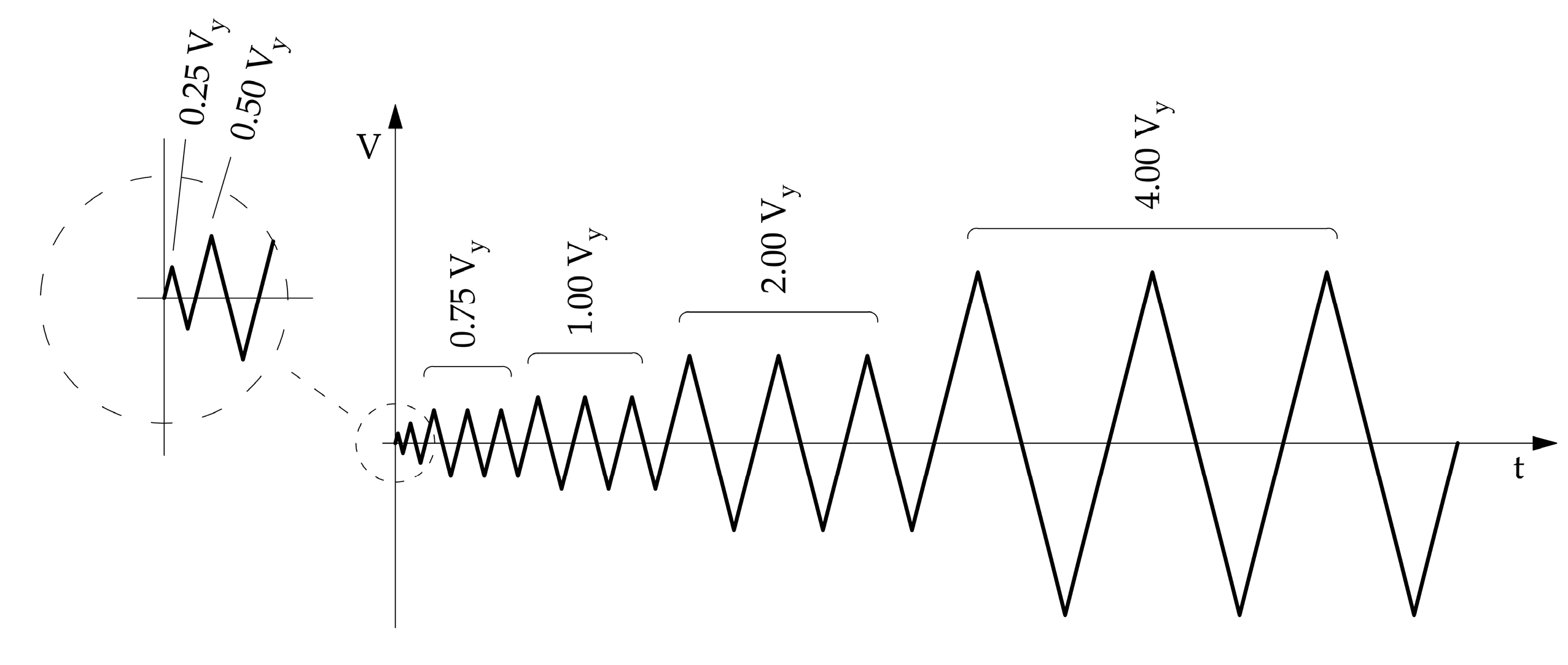
Figure 4.
Test setup and instrumentation.
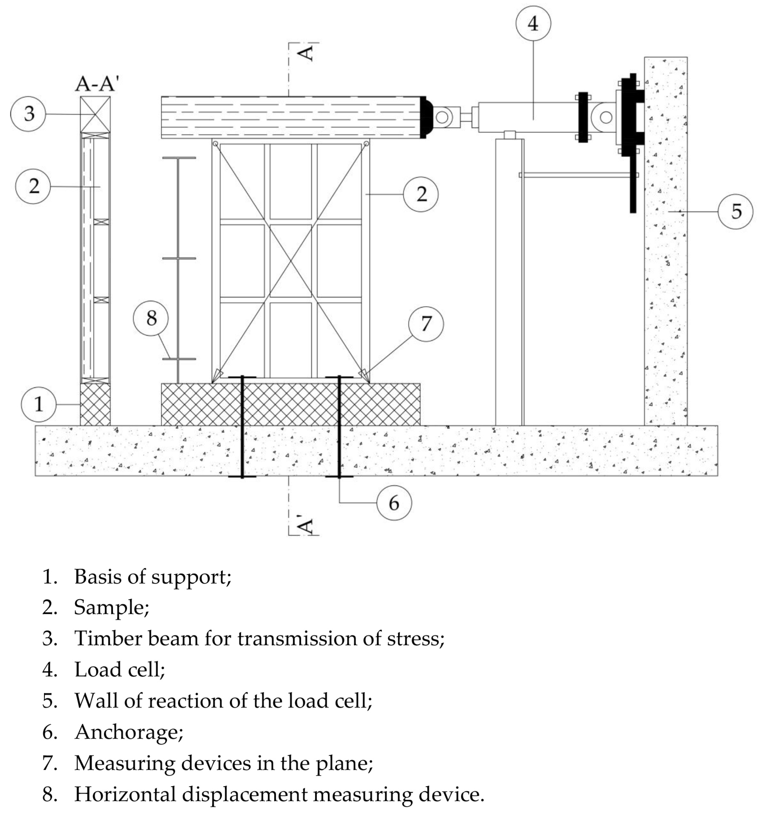
Figure 5.
Fixation of the panels to the base. (a) Fixation with steel rods; (b) fixation with hold-down.
Figure 5.
Fixation of the panels to the base. (a) Fixation with steel rods; (b) fixation with hold-down.

Figure 6.
Detail of the fixation of the load-cell to the top beam responsible for the application of the loading protocol.
Figure 6.
Detail of the fixation of the load-cell to the top beam responsible for the application of the loading protocol.

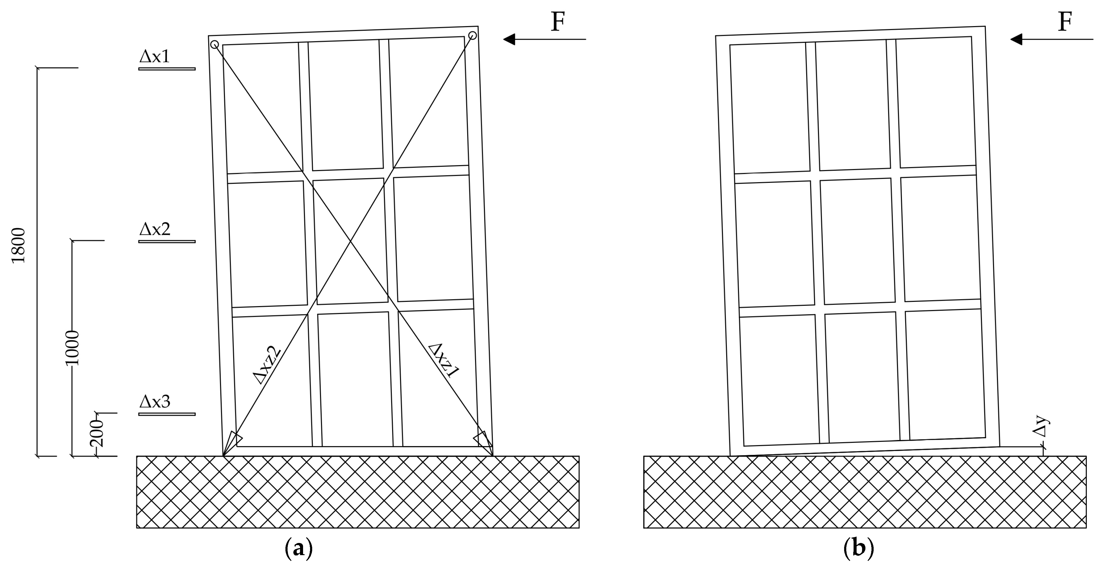
Figure 7.
Plan of the instrumentation used (dimensions in mm). (a) In-plane deformation; (b) rotation (rocking movement).
Figure 7.
Plan of the instrumentation used (dimensions in mm). (a) In-plane deformation; (b) rotation (rocking movement).

Figure 8.
Force-displacements experimental curves collected during tests F, S and D.
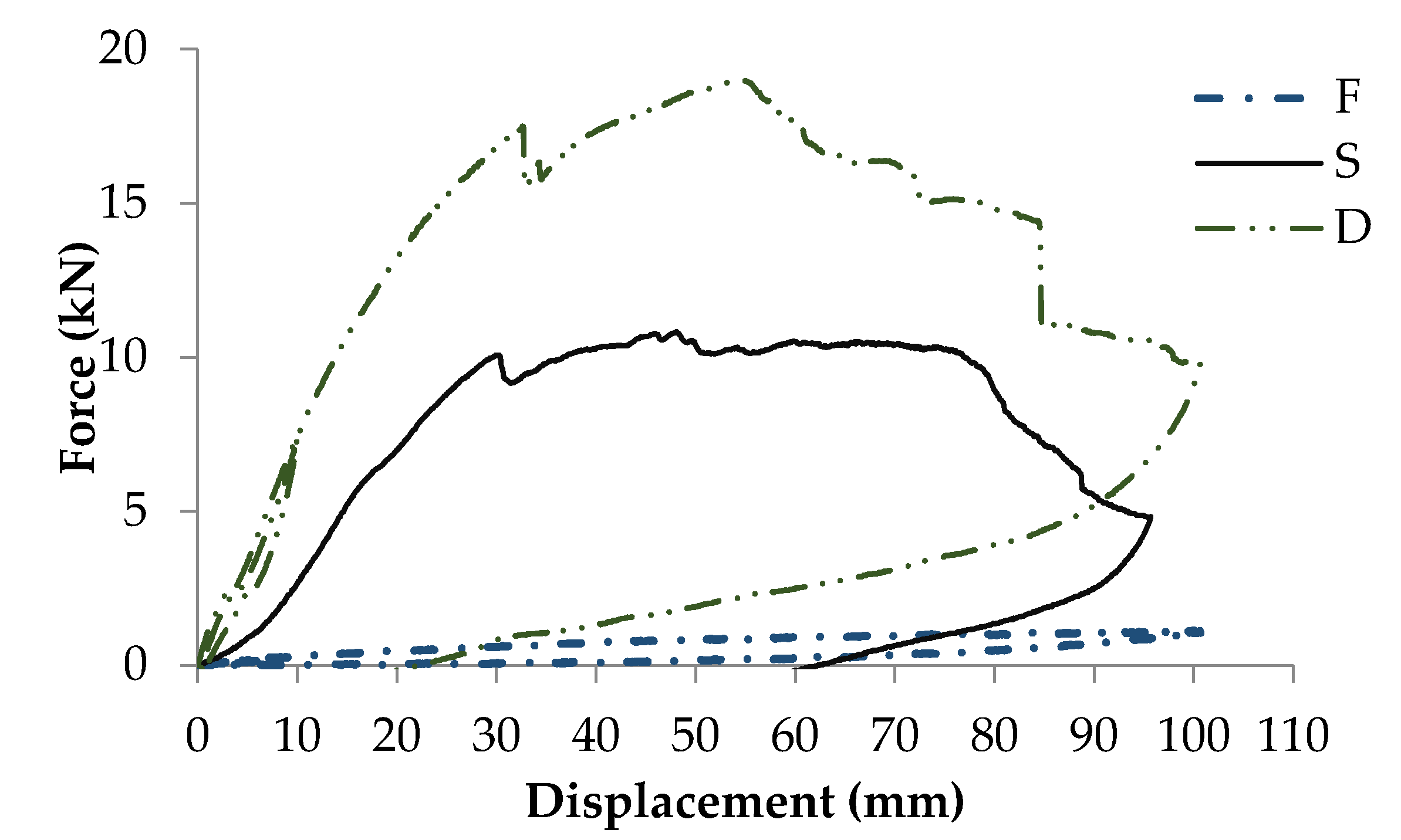
Figure 9.
Specimen P: (a) Deformation of the sample and; (b) Rotation failure.
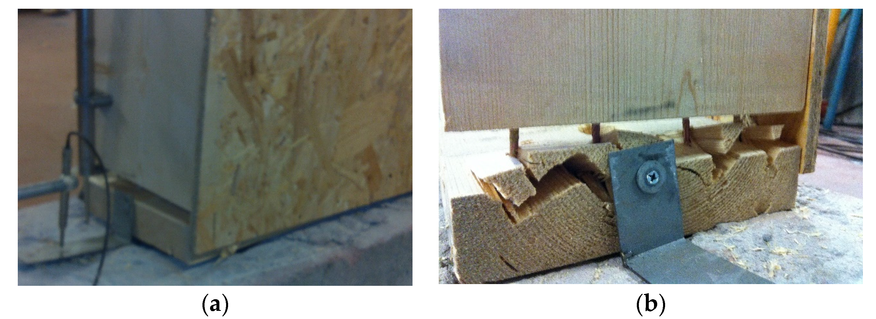
Figure 10.
Specimen D: (a) Deformation of the sample and; (b) Rotation failure.
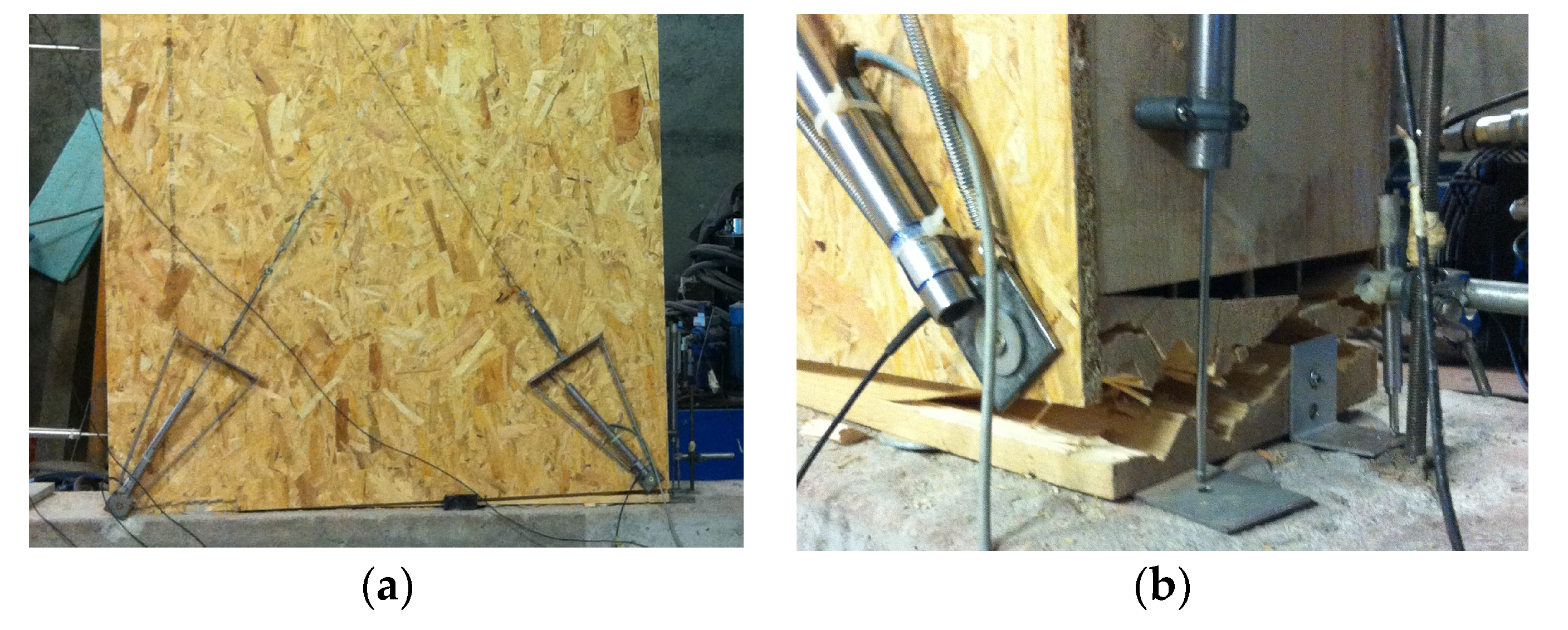
Figure 11.
Experimental force-displacement obtained from specimens DH and DHC.


Table 1.
Description of the specimens tested. First specimen evaluated (F); second specimen considered (S); third specimen evaluated (D); fourth specimen evaluated (DH); fifth specimen evaluated (DHC).
Table 1.
Description of the specimens tested. First specimen evaluated (F); second specimen considered (S); third specimen evaluated (D); fourth specimen evaluated (DH); fifth specimen evaluated (DHC).
| Name | Description | Fixation to the Base | Loading |
|---|---|---|---|
| F | Timber structure | Steel rods (concrete base) | Monotonic |
| S | Timber structure and 11 mm OSB sheathing on one side | ||
| D | Timber structure and 11 mm OSB sheathing on both sides | ||
| DH | Timber structure and 11 mm OSB sheathing on both sides | Hold-downs (timber base) | |
| DHC | Timber structure and 11 mm OSB sheathing on both sides | Hold-downs (timber base) | Cyclic |
Table 2.
Results of the cyclic test DHC. Impairment strength (ΔF).
| Range | Fmax (kN) | Ed (kN.mm) | EP (kN.mm) | Veq (%) | ΔFt (kN) | ΔFc (kN) |
|---|---|---|---|---|---|---|
| [18.75; −18.75] | 12.97 | 121.20 | 91.63 | 21.05 | 0.71 (5.47%) | 0.63 (5.14%) |
| [25.00; −25.00] | 15.65 | 199.48 | 125.85 | 25.23 | 0.95 (6.09%) | 1.03 (6.58%) |
| [50.00; −50.00] | 25.88 | 647.00 | 291.91 | 35.28 | 3.32 (12.83%) | 3.89 (15.98%) |
Table 3.
Results of the tests.
| Specimen | Fmax (kN) | Stiffness (N/mm) | Elastic Displacement (mm) | Ultimate Displacement (mm) | Ductility | |||
|---|---|---|---|---|---|---|---|---|
| kISO | km | k0 | k1 | Vy | Vu | D | ||
| F | 1.14 | 22.71 | 25.80 | 22.70 | 3.80 | 37.56 | 96.51 | 2.22 |
| S | 10.83 | 445.07 | 439.40 | 445.10 | 74.200 | 23.86 | 80.6 | 3.38 |
| D | 19.03 | 722.66 | 761.80 | 722.70 | 120.40 | 20.07 | 72.59 | 3.62 |
| DH | 40.50 | 949.96 | 974.60 | 950.00 | 158.30 | 32.16 | 99.89 | 3.11 |
| DHC | 34.26 | 686.55 | 689.10 | 686.50 | 114.40 | 45.57 | 65.45 | 1.44 |
kISO—Elastic stiffness (ISO/FDIS 21581); km and k0—Elastic Stiffness (EN 12512); k1–Post-elastic Stiffness (EN 12512).
Table 4.
Properties of specimen DH.
| Geometrical and Mechanical Properties | Symbol | Value |
|---|---|---|
| Length (mm) | l | 1250 |
| Height (mm) | h | 1950 |
| Vertical load (kN/m) | q | 0 |
| Number of braced sides | ηbs | 2 |
| Sheathing panel shear modulus (N/mm2) | Gp | 1080 |
| Sheathing panel thickness (mm) | tp | 11 |
| Sheathing panel length (mm) | b | 1250 |
| Fasteners stiffness (N/mm) | kc | 18,782 |
| Fasteners spacing (mm) | Sc | 1230 |
| Hold-down stiffness (N/mm) | kh | 4000 |
| Angle bracket or screws stiffness (N/mm) | ka | 18,782 |
| Number of angle brackets or screws | ηa | 2 |
Table 5.
Comparison of the experimental values obtained for the displacement of the wall with the ones predicted by the analytical model.
Table 5.
Comparison of the experimental values obtained for the displacement of the wall with the ones predicted by the analytical model.
| Force (kN) | Displacement (mm) | Error (%) | |
|---|---|---|---|
| Analytical | Experimental | ||
| 10 | 7.92 | 10.36 | 23.59% |
| 20 | 15.84 | 20.89 | 24.19% |
| 30 | 23.76 | 31.42 | 24.38% |
| 40 | 31.67 | 41.94 | 24.48% |
Table 6.
Comparison between experimental and analytical stiffness values of the analyzed wall.
| Method | Stiffness (N/mm) | |
|---|---|---|
| Experimental | Kiso = 949.96 | Km = 974.60 |
| Analytical | Ktot = 1262.86 | |
| Error | 24.78% | 22.83% |
© 2017 by the authors. Licensee MDPI, Basel, Switzerland. This article is an open access article distributed under the terms and conditions of the Creative Commons Attribution (CC BY) license (http://creativecommons.org/licenses/by/4.0/).
Share and Cite
MDPI and ACS Style
Branco, J.M.; Matos, F.T.; Lourenço, P.B. Experimental In-Plane Evaluation of Light Timber Walls Panels. Buildings 2017, 7, 63. https://doi.org/10.3390/buildings7030063
AMA Style
Branco JM, Matos FT, Lourenço PB. Experimental In-Plane Evaluation of Light Timber Walls Panels. Buildings. 2017; 7(3):63. https://doi.org/10.3390/buildings7030063
Chicago/Turabian StyleBranco, Jorge M., Filipe T. Matos, and Paulo B. Lourenço. 2017. "Experimental In-Plane Evaluation of Light Timber Walls Panels" Buildings 7, no. 3: 63. https://doi.org/10.3390/buildings7030063
Note that from the first issue of 2016, this journal uses article numbers instead of page numbers. See further details here.