Article

Improving Natural Ventilation Conditions on Semi-Outdoor and Indoor Levels in Warm–Humid Climates

Department of Architecture, Faculty of Environmental Design, King Abdulaziz University, Jeddah 21589, Saudi Arabia
Buildings 2018, 8(6), 75; https://doi.org/10.3390/buildings8060075
Submission received: 11 April 2018 / Revised: 19 May 2018 / Accepted: 24 May 2018 / Published: 28 May 2018

Abstract

:
Building form and facade development for energy saving and generation are of great importance. Further development for natural ventilation purposes is also imperative as it is related to many issues that affect the quality of the living and working environment inside and around the buildings in outdoor and semi-outdoor spaces. In rapidly developing regions experiencing a warm and humid climate, like Saudi Arabia, mechanical cooling and ventilation are commonly used in residential and non-residential buildings. However, this was not the case in traditional structures, like the massive coral buildings of Jeddah, where cooling essentially depended on cross ventilation and heat storage in thermal mass. Further, the building forms in the traditional oriental city were optimized for natural ventilation on the macro- and micro-urban and room scales, respectively. Owing to the advancement in air-conditioning technology, conventional building design approaches tend to encourage sealed indoor spaces that rarely interact with the outdoor environment. Even in such harsh climates, during many months in a year, the outdoor temperature is remarkably low, allowing the utilization of natural ventilation within the rooms, as well as between building complexes and the surrounding spaces. This optimization process requires the integrated planning of many aspects, such as the facade, building form, as well as the intermediate threshold spaces between the indoor and outdoor spaces. Non-residential buildings in Saudi Arabia require a large amount of energy for operation. This is mainly due to the relatively high cooling demand caused by internal loads. A hybrid cooling system that incorporates mechanical and natural cooling and ventilation can be implemented for low-temperature days and nights. This paper presents a method for saving energy in a university faculty building, which is located in Jeddah. Models of the proposed solutions were analyzed using a computational fluid dynamics simulation tools, as well as the dynamic building simulation tool IDA-Indoor Climate and Energy (IDA-ICE) to assess user comfort and the level of reduction in energy demand.

1. Introduction

Providing a healthy living, working or education environment that promotes thermal and olfactory comfort is essential for the performance and satisfaction of the users. Natural ventilation is a passive technique that helps remove foul air and moisture, as well as provide occupants with thermal comfort under certain conditions. It is a key factor in preventing the spread of airborne illnesses, while reducing the CO2 concentration in a space [1]. Compared to mechanical ventilation, natural ventilation requires little technical effort, maintenance, and above all, energy use [2,3]. However, some risks, such as outdoor air pollution, noise, and dust may arise and must be prevented [4]. Indigenous buildings in warm-humid regions are often marked by increased permeability to allow cross ventilation where wind is given a pathway through the structure. Openings should be large, with similarly sized inlets for wider circulation of air [5,6]. A hot–humid climate, such as that of Jeddah, Saudi Arabia, requires a passive cooling solution that helps eliminate the energy use of active air conditioning systems. Providing a hybrid system (passive/active) is fundamental in a building that boasts environmental stewardship. However, unlike mechanical ventilation, the desired conditions for natural ventilation (i.e., air temperature, humidity, velocity, and quality) are often less predictable and controllable due to the complexity of the influencing factors. In the early building design stage, it is sensible to optimize the building form and window openings as much as possible to ensure best conditions for natural ventilation and airflow through the building structure.
Heat dissipation from the skin is a type of physiological cooling. Several studies have shown that users are able to tolerate high thermal temperatures under certain conditions by elevated air velocities [7,8,9,10,11,12,13]. In particular, a study by Fountain and Arens [7] is a comprehensive review that outlines research investigating the impact of moving air on thermal sensation and the comfort limits of air velocity, which is crucial for avoiding drafts. Under certain warm conditions, other investigations by Arens [11] suggest that higher air velocity reduces the demand for air cooling. In particular, people tend to accept higher operative temperatures while wearing light clothes. This is because higher air velocity accelerates the extraction of heat from the body surface per sensible heat exchange, which essentially improves the level of thermal satisfaction among the occupants. Furthermore, it was found that users become more tolerant to high-air velocities and operative temperatures when they can control the air supply volume [11]. The significance of increased air velocity on user comfort in warm-humid climates has been discussed by Schiavon et al. and Bayoumi [14,15]. This suggests the importance of providing natural ventilation, as well as hybrid ventilation. In the latter approach, mechanical ventilation supports natural ventilation when needed under specific conditions. Some international heating, ventilation, and air conditioning (HVAC) planning standards, such as ANSI/ASHRAE Standard 55-2004, have recently included provisions that integrate hybrid ventilation and cooling techniques based on elevated velocities [11]. Generally, natural ventilation takes advantage of both wind and buoyancy to circulate fresh air through a building. Air movement performs three separate functions: supplying fresh air for health, cooling the interior by convection, and cooling the inhabitants under certain conditions. Wind-driven ventilation occurs because of pressure differences. As the wind blows against a structure, air piles up on the windward side, creating an area of high pressure. With the air flowing around the building, an area of reduced pressure is created directly downwind of the structure. Thus, a difference in pressure exists between the different faces of envelop of the structure, causing the air to move through it.
This paper depicts the impact of decisions for energy saving and comfort enhancement using natural ventilation for a building in Jeddah, Saudi Arabia. The building was designed to house an architectural faculty in King Abdulaziz University. The aim is to present methods to eliminate the dependence on mechanical cooling and ventilation in buildings in hot–humid climates. The demonstrated investigations were conducted simultaneously with the early conceptual architectural design development. It is believed that such investigations on building performance should be conducted at preliminary design phases, when changes to the building structure and facade configurations are easy and less costly to implement [16]. The study presents the following:
  • Impact of form enhancement process on wind velocity in public zones such as: ground floor, common rooms, corridors, and roof space. The analysis is made using ANSYS-CFX for computational fluid dynamics (CFD).
  • Possible reductions in cooling energy demand and the associated air quality in the of different room cooling and air conditioning methods including hybrid ventilation with an integrated radiant cooling system in a typical classroom space. The dynamic building simulation tool IDA-Indoor Climate and Energy (IDA-ICE 4.7) was used to model the problem of the generic classroom and investigate the feasibility of the different approaches.

2. Methods

2.1. General Framework

The city of Jeddah is located in a subtropical climate region, which is generally characterized by high temperature and high relative humidity. The outdoor temperature in Jeddah can reach up to 45 °C in the daytime during summer. However, for a considerable amount of time, from November to May, the mean outdoor temperature lies within the human comfort zone of 20–28 °C. The left diagram in Figure 1 outlines the average monthly temperatures. The right diagram depicts the window opening potential in each month. The filled columns represent the times where temperature (Ta) is less than 30 °C. The unfilled columns indicate the total number of hours per month. Moreover, during the evenings in summer, when the temperature is at its lowest, it is within the thermal comfort zone. The high moisture content in the air causes discomfort that can be prevented using elevated air velocities within a specific framework. The prevailing wind directions with the highest frequency of occurrence are north and northwest, with an average velocity of 2.5 m/s at the reference level.
The left and central images in Figure 2 demonstrate the basic structure of the building. The slices/sections analyzed are highlighted in light blue. A sample classroom, with 50% openings on the leeward side (regarded as the worst case), was selected for further investigations to determine the potential of the suggested hybrid approach on energy saving. The image on the right shows the sample classroom, which was further modeled using IDA-ICE.

2.2. Numerical Simulations

Steady-state simulations were conducted with the help of ANSYS-CFX 15.0, a software that solves the equations of CFD and supports the analysis of airflow, as well as velocity around and through certain zones in the proposed design. These analyses helped in fundamental decision-making related to the building form, height, and massing configurations, as well as openings in the facade. While the CFD simulation tools have undergone great developments in the past years, it is important to consider their limitations which have been discussed by many researchers [17,18,19]. The uncertainties of these tools are usually associated with the turbulence model, calculation mesh, and other boundary settings like the atmospheric boundary layer.

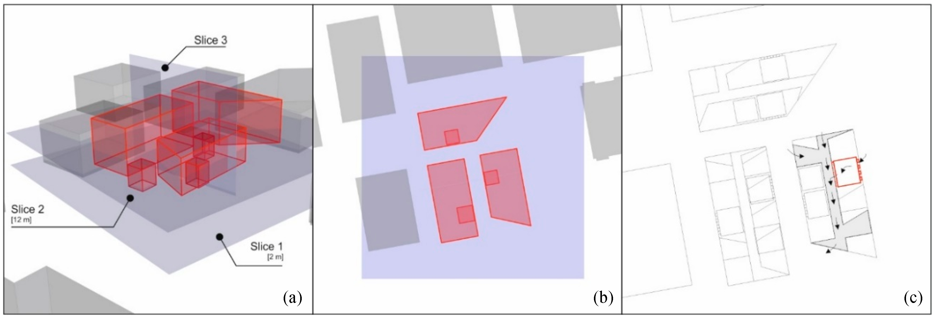
2.2.1. Modeling of the Atmospheric Boundary Layer

As wind speed increases with height, it was essential to generate the appropriate wind profile to the project site to take the effect of the atmospheric boundary layer into consideration [20]. Two “laws” are generally used to extrapolate the wind velocity profile with respect to the surface roughness of the site: the power law and the logarithmic law. Due to the complexity of turbulent flows, both models are subject to uncertainty. Moreover, the logarithmic law was introduced by Stull [21] and contains a thermal correction factor that models the impact of thermally-induced wind movement. Moreover, in the fields of wind engineering and environmental aerodynamics, the power law, which was originally introduced by Hellmann [22], is considered pertinent [23].
In the present study, neither buoyancy-induced ventilation nor outdoor air pollution are directly considered in the investigation. Therefore, the power law, which is shown in Equation (1), is considered in the modeling of the wind profile. Therefore, the calculation of air velocities at every height was made using the power law method described by Peterson [24], which is mentioned in Equation (1) and indicated as U. While Ur represents the wind velocity at 10 m height, Z refers to the changing heights. The reference height of the source of climate data is usually equivalent to 10 m and written as Zr. α is the variable that describes the surface roughness factor of the surrounding area which was set to 0.28 [25]. This factor corresponds to a suburban condition [26] which represents the nature of the site of the university campus where the case study project is located. Furthermore, the surrounding masses and structures have also been modelled with rough no-slip walls including the ground to provide a better approximation for the turbulence condition.
U = ( Z Z r ) α · U r
Further, the CFD part of the study is limited to wind-induced ventilation where the relationships between building form, openings, and wind velocity are explored. The issues related to the age of air and CO2 concentration in the space are computed in another dynamic simulation environment (IDA-ICE) where buoyancy and the associated thermal effects are considered. Table 1 outlines the basic configurations used in the CFD analysis.

2.2.2. Governing Equations

The modelling of the flow around buildings and through the case study building in the CFD software was made using the governing equations that describe the incompressible turbulent fluid flows. Equation (2) expresses the continuity equation followed by the Reynolds-averaged Navier–Stockes equation:
u i x i = 0 ,
x j ( ρ u j u i ) = P x i + x j [ μ ( u i x j + u j x i ) ρ u i u j ¯ ]
The modelling of the turbulent flow was made using RNG kε [27] which has been used in the modelling of turbulent flow around buildings in several cases [28]. Another work by Stamou and Katsiris [29] validated experimentally several turbulence models to analyze airflow and the associated heat exchange. According to the researchers, the RNG kε is a reliable model. It can be used for practical purposes. In this model, the ε which is the turbulence dissipation rate is modified, which is the main difference from the standard model of standard kε. Moreover, this turbulence model can be expressed according to the following equations:
ρ u i u j ¯ = μ t ( u i x j + u j x i ) 2 3 δ i j ρ k
x j ( ρ u j k ) = x j [ ( μ + u t σ k ) k x j ] + μ t ( u i x j + u j x i ) u i x j ρ ε
x j ( ρ u j ε ) = x j [ ( μ + u t σ ε ) ε x j ] + C 1 ε k μ t ( u i x j + u j x i ) u i x j C 2 ρ ε 2 k
where
k = 1 2 u i u j ¯ ,   ε = μ ( u i x j ) ( u j x i ) , ¯   μ t = C μ ρ k 2 ε
C 1 = 1.42 η 1 η / η 0 1 + β η 3
η = S k ε ,   S = ( 2 S i j S i j ) 1 2
S i j = 1 2 ( u i x j + u j x i )
The mean and turbulent velocity components in x i direction are represented by u i and u i , respectively. Also, δ is the grid element length. The variable P refers to the mean pressure. ρ stands for the density of the fluid. The turbulence kinetic energy is represented by k . S is a variable that describes the derivative of the strain tensor with respect to time. μ as well as μ t are the molecular and eddy viscosity, respectively. The model constants are as follows:
C μ =   0.085 ; C 2 = 1.68 ;   σ k = 0.7179 ; σ ε = 0.7179 ;   σ ρ = 1.0 ;   β = 0.015 ;   and   η 0 = 4.38

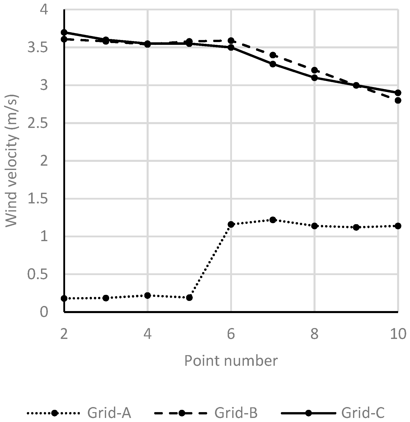
2.2.3. Grid Independence Analysis

To conduct grid independence simulations, the air velocity at a set of points on a certain height was investigated in the three grid cases: Grid-A: 1,043,921 cells, Grid-B: 1,677,319 cells, and Grid-C: 2,282,677. This indicates an increase in the number of grids in Grid-B and Grid-C by 1.6 times and 2.2 times, respectively. Several grid independence analysis methods have been reviewed [30,31]. The analysis was done in the undisturbed free stream (points height = 12 m).
According to the diagram in Figure 3, Grid-A indicates a large difference in the wind velocity against Grid-B. Comparably, a little discrepancy between the second and the third grids can be seen. Therefore, to save simulation time, the further simulations were conducted using Grid-B.

2.3. Dynamic Building simulations

Preliminary research investigations into the climate characteristics in Jeddah showed that window ventilation is possible for up to six months [4]. A simulation was conducted for a classroom located on the leeward side and highlighted in red in Figure 2. Using IDA-ICE, three different cooling methods and control strategies were implemented on the case study room: Case 1 (temperature-controlled air conditioning), Case 2 (radiant cooling system; e.g., chilled ceiling) with a CO2-controlled variable air volume (VAV) system, and Case 3 (in addition to Case 2, the four windows on the facade were programmed to open automatically if the outdoor temperature was lower than 25 °C). Bayoumi [4] has proven the effectiveness of this approach under the same climate characteristics. Further details on the configuration of the simulated room surfaces can be seen in Table 2. The conducted simulations were made for the entire year. The resulting data have been averaged for each of the four seasons.
The following table provides an overview of the internal loads that have been modelled in the dynamic thermal simulation software. Also, 1000 ppm is the default threshold for CO2 concentration. If this value has been reached, the fresh air supply is turned on invoked. The software also calculates internally the heat dissipation and moisture generated by the occupants of the simulated room. Table 3 outlines the elements that cause internal cooling loads.
In hybrid ventilation where the radiant cooling system is used, condensation is one of the essential challenges that needs to be considered. Issues related to mold growth, which are associated with the condensation potential, are not within the scope of this paper. However, a method to overcome this problem can be reviewed in Reference [32]. Further discussion can be seen in References [33,34].
The simulation model considered a room with a window fraction of 50%. The default discharge coefficient of 0.65 for each window was not modified. Mainly, the impact of buoyancy driven facade ventilation could be analyzed. The potential of coupling wind driven facade ventilation with naturally ventilated corridors over an opening in the wall was not considered in this work and can be investigated in a further study.

3. Results and Discussion

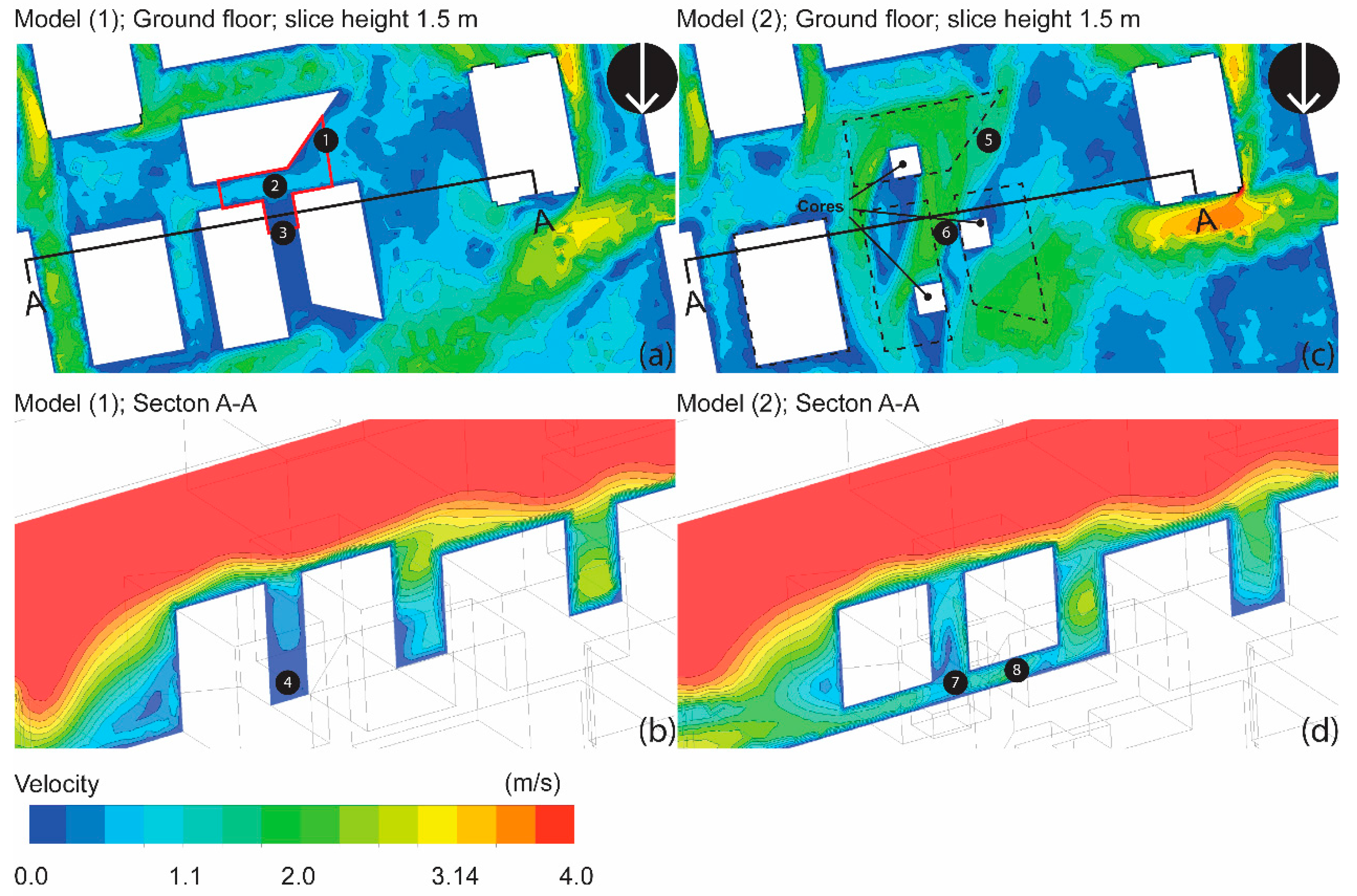
3.1. Development of Building Complexes to Enhance Airflow as well as Ground Floor Interaction with the Outdoor Environment

The basic simulation case relates to the conventional treatment of the ground floor. It is apparent from the results displayed in Figure 4 that the fixed building complexes at the ground level, which is represented by Model (1), play a substantial role in blocking wind movement. Interestingly, the 45° cut for the northern building complex allows the north wind to flow through. While this opening provides increased air velocity at point (1) towards the other side over point (2), a very calm condition can still be noticed at point (3) along the urban canyon space that separates the right- and left-hand parallel complexes. This also limits the opportunity to ventilate the enclosed common spaces on the ground floor (e.g., atrium) naturally under cool weather conditions. The limits of the atrium area are highlighted in Figure 4 in red.
It is clear that this option of Model (1) has very limited potential. The expected low air exchange rate is one of the main drawbacks of this approach. This effect can be clearly observed at point (4) where calm air remains in the bottom. Further, due to the increased height of the side walls of the urban canyon, the lower part is not substantially affected by the skimming effect that is taking effect on the higher levels, which obviously causes an increase in wind velocity.
The ability to open the ground floor completely adds immensely to the ventilation quality of the built structure. It basically increases the wind flow through the building, while on the other hand, it provides a high level of air exchange. Passive air exchange is not only psychologically pleasing, but also saves energy. The results of the second case, Model (2), namely considering permeable and openable ground floor walls, as well as operable windows along the corridors, are displayed in the right-hand column in Figure 2. Moreover, an open-building approach provides continuous air movement, which is preferred in hot–humid climates, especially when the outdoor temperature does not change drastically from daytime to nighttime. In this case, daytime cross-ventilation is encouraged when the outdoor temperature is acceptable, to meet user comfort with passive techniques. It is clear that the cores which remained fixed in this option left calm areas behind them. This so-called wake effect occurs with only certain wind directions. However, the design can be optimized further to eliminate this impact. A remarkable increase in air speed at points (5) and (6) can be observed. Points (7) and (8) indicate a breeze penetrating the ground floor on its way to the open plaza next to the building. One drawback of this option is the increase in wind velocities at the roof tops, which makes the integration of a roof garden rather challenging.

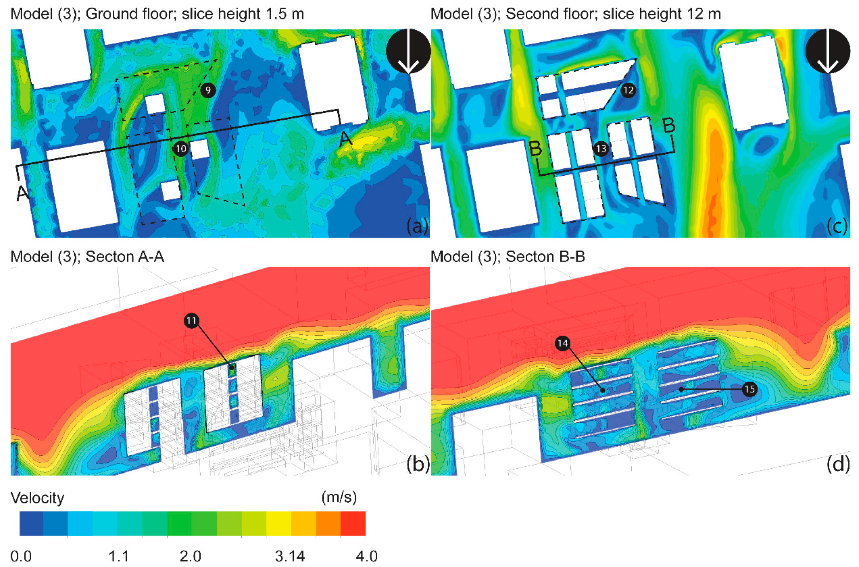
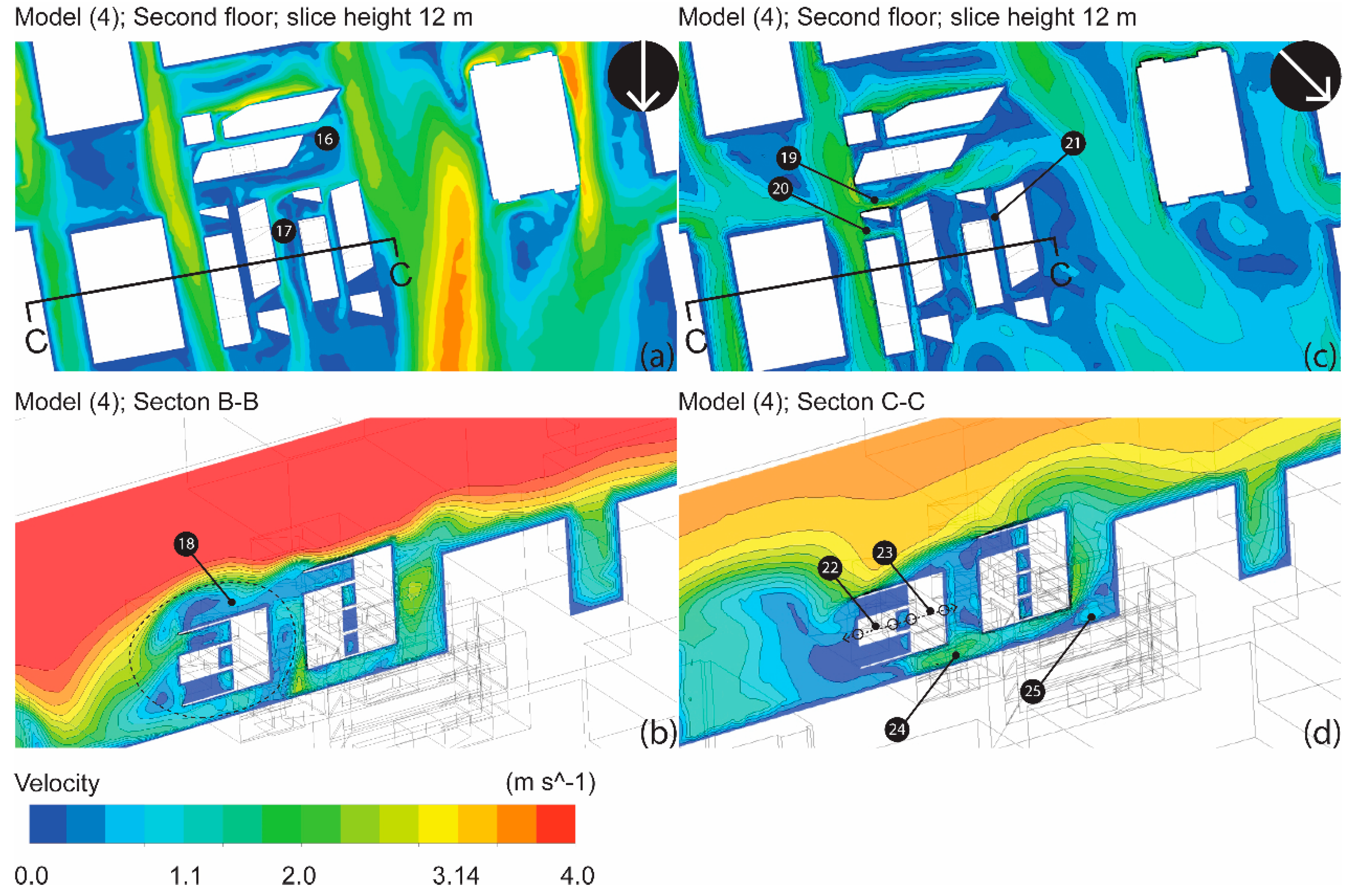
3.2. Providing Cross Ventilation in the Circulation Zones of Typical Floors

Providing wind catchers in the form of openings on each side of the building is an enhancement method used to increase air exchange through the corridors. This option also works well when enclosed areas like offices, studios, and classrooms are in the mechanical ventilation mode, with users unwilling to use natural ventilation. From the diagrams in Figure 5, the side openings introduced on the upper floors greatly improved the wind situation on the ground floor where the velocity goes up to 2.1 m/s. An air velocity of approximately 1.8 m/s was also noted at test points (9) and (10) in Figure 3. This indicates that the center of the atrium is well-ventilated. The flow along the urban canyon at point (10), as well as the upper corridors, seems to be unobstructed and seamless. This effect is significant in case of fire, allowing smoke to be extracted with lesser effort.
The area between the east and west complexes over the urban canyon at point (11) depicts a wind-induced ascending volume of air with a velocity reaching 1.1 m/s. It is also supported by the wind flowing over points (12) and (13). In other words, the elevated building mass and reduced height allow for the circulation of air streams, promoting air exchange, with the potential for natural ventilation and passive ventilation. Points (14) and (15) show a remarkable increase in wind velocity after providing a crossing corridor with an opening at both ends. This indicates the importance of developing this approach to benefit from increased wind movement.
Note section A-A, which cuts through the north complex and continues along the pedestrian walkway; the increased air velocity is one of the most striking findings of this optimization step. The shaded area offers potential as one of the most interesting spaces in the project; students’ projects can be displayed, discussed, and even designed here.

3.3. Enhancement of Roof Condition as well as Wind Catching Spaces

As in Model (4) shown in Figure 6, with wind blowing from the north, the corridors of the northern and eastern parts, as well as above the urban canyon, the wind velocity reaches higher than 0.5 m/s. This is seen in points (16) and (17). From the images on the left side, downsizing the eastern building complex by one floor provides not only the potential for a roof garden at point (18), it also protects the people on the roof from strong winds and helps improve their thermal sensation via moderate wind velocity. It is also notable that pleasant wind conditions are created on the ground floor. The effect of the wind catching openings on the facades is apparent on the upper floors. The corridors seem to be well-ventilated.
It is also essential to study the performance of the conceptualized form with respect to the northwesterly wind direction. Increased air velocity at points (19) and (20) can be seen. This also includes the corridor in the western part of the building at point (21) which is impacted by the side opening to the west. Moreover, an expected decrease in air velocity by ca. 0.8 m/s compared to the point (12) can be seen along the corridor in the eastern part of the building. The main cause of this effect is the lack of openings towards the windward side. To overcome this situation, openings from both sides, as well as along the corridors are recommended, to increase air velocity.
Providing openings over the classroom doors or even through the door will improve the air movement between the facade and the corridor as indicated in points (22) and (23), thus maximizing cross ventilation in the building. This is helpful to flush the classrooms during break times between classes, for instance, to maintain high air quality.
While the wind flow along the urban spine is weaker than that of the north wind, which can be experienced at test point (24), the pedestrian level is only mildly affected by the change in wind direction. At point (25), there is increased air velocity between the building and neighboring building to the west, which is highly advantageous for such public spaces. Also, at the ground level, the neighboring plaza to the west of the site allows more wind to enter the building and ventilate this ground. Interestingly, the wake effect behind the cores was remarkably eliminated. It also appears that the plaza to the east of the building receives more air with increased velocity.

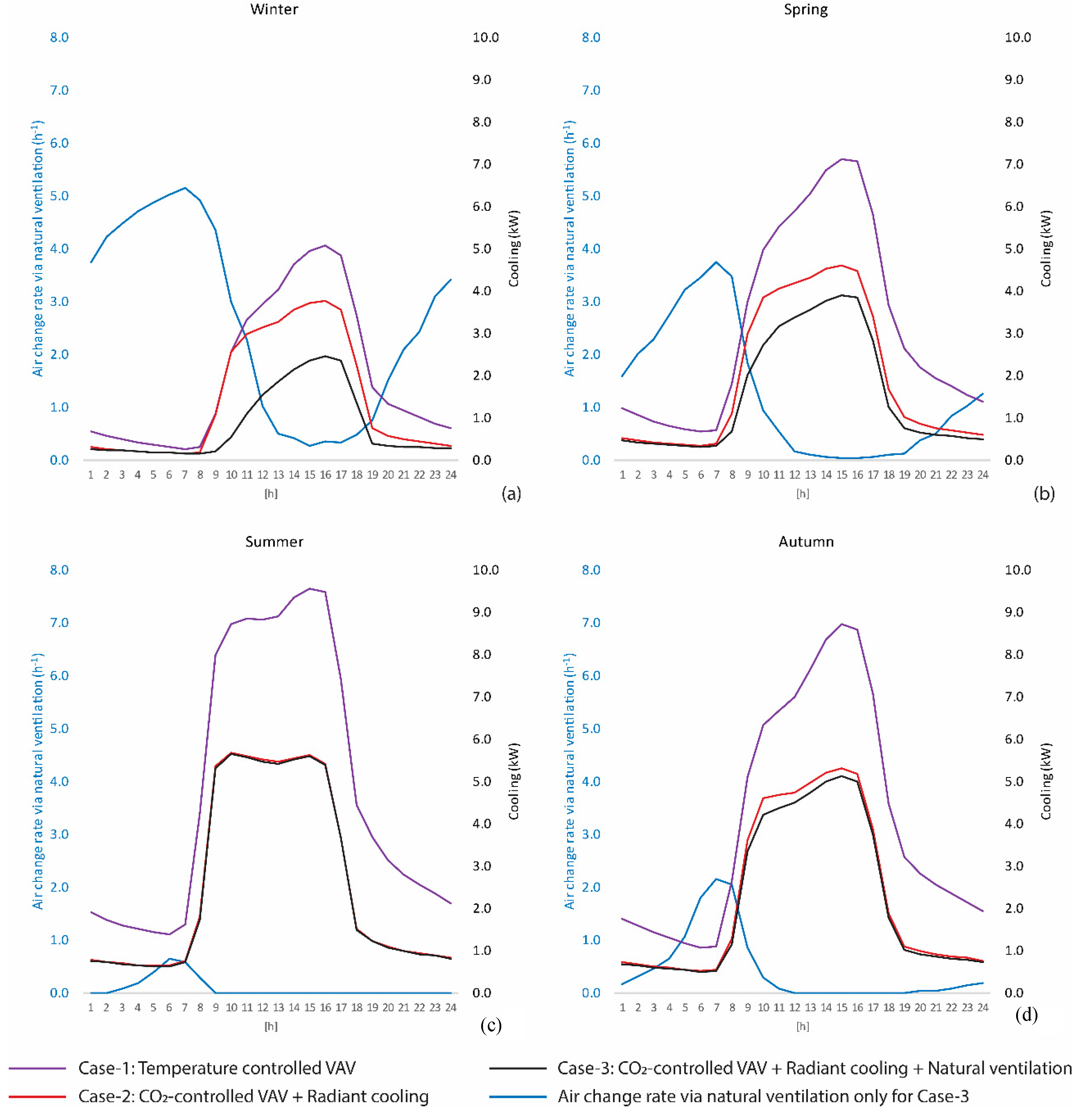
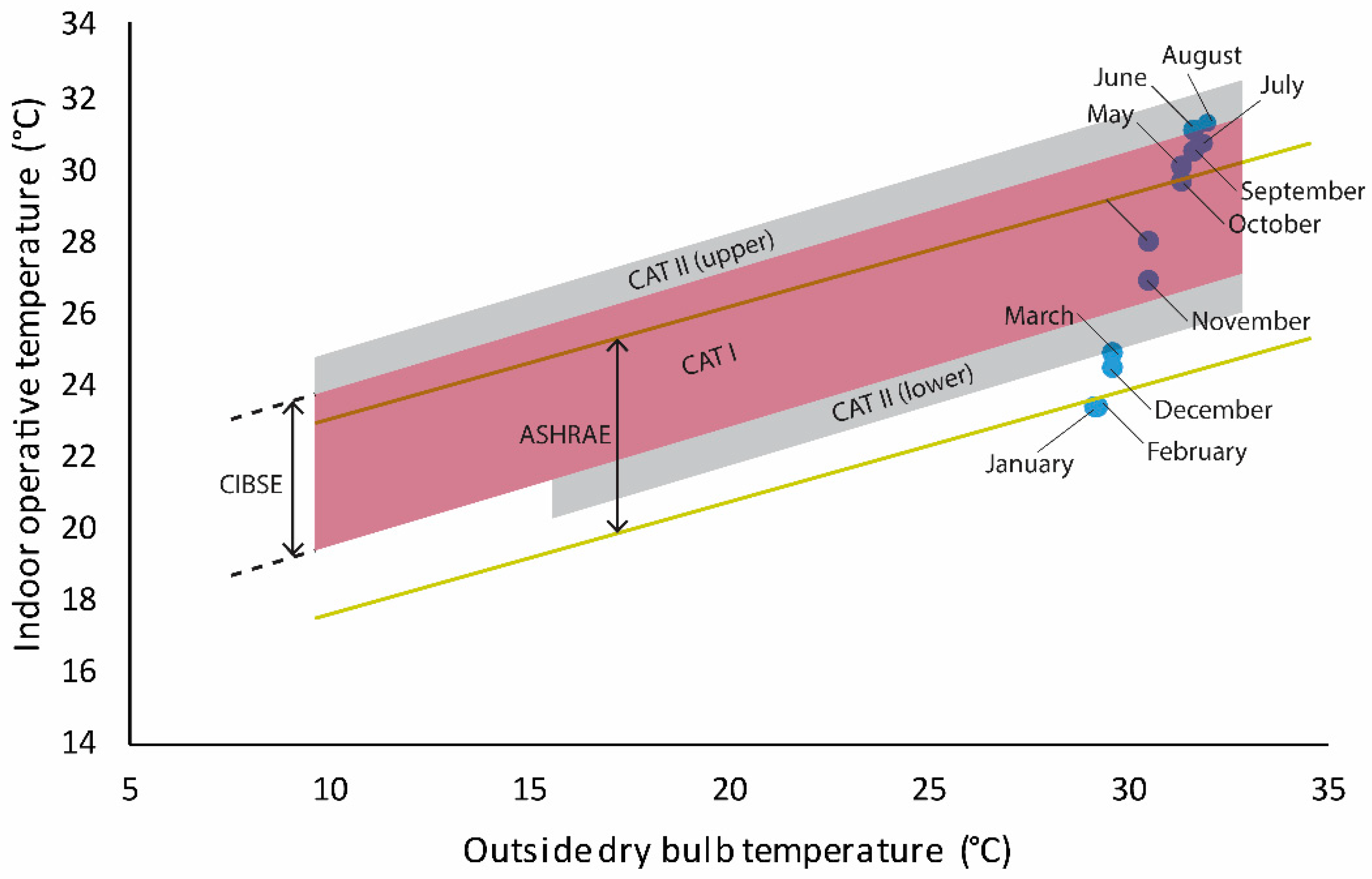
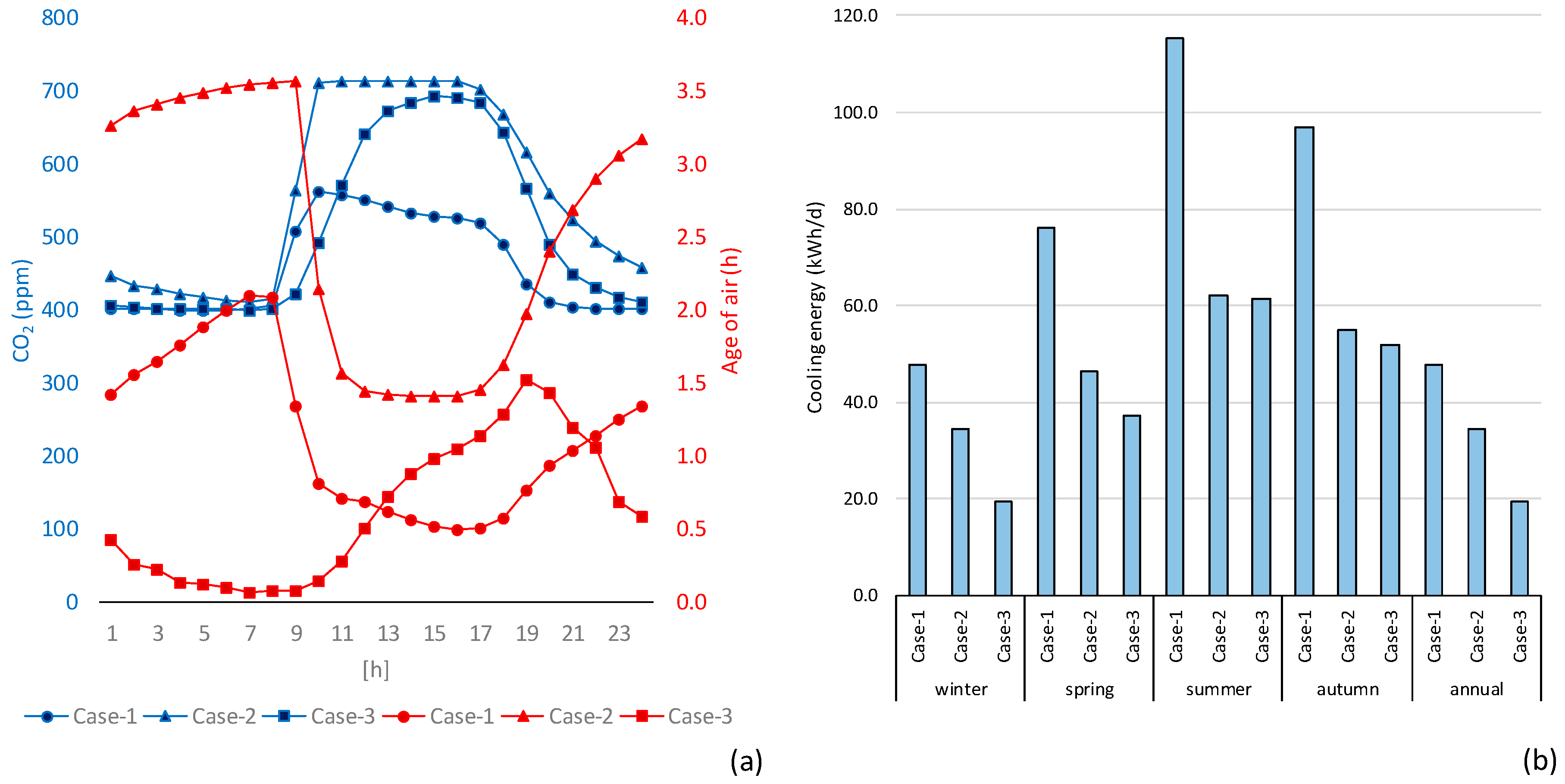
3.4. Impact of Window Ventilation on Reducing Cooling Loads in A Hybrid Cooling System

The four diagrams in Figure 7 demonstrate the results of the three cooling methods. The results are presented on an average day of each season. The primary axis represents the expected air change rate via natural ventilation and applies only to Case-3, while the secondary axis shows the cooling load. The purple line in Case-1 represents the cooling load by the conventional VAV air intake that is controlled by the room temperature, which was limited to 21–25 °C. The red curve presents the results for Case-2, with the air intake changed to a VAV controlled by CO2 sensors that maintained an air quality zone between 700 and 1100 ppm. The temperature of the supplied air was 16 °C. Further, a radiant cooling system was considered for the extraction of cooling loads that were not removed by mechanical ventilation. The model for Case-3, which is represented by the continuous black curve, included a control system that keeps the window open by acceptable outdoor temperature. The window closing threshold is 25 °C.
According to Figure 7, it is obvious that the cooling load in Case 2 is substantially low compared to Case 1. Further, the results of Case 3 demonstrate much lower cooling loads, especially in winter and spring. This indicates that the conventional air-conditioning methods using only air is energy intensive, while a radiant cooling system helps to increase the energy efficiency. Window ventilation can considerably reduce the cooling load.
The adaptive thermal comfort model for natural ventilation is a practical evaluation tool to determine the level of comfort with respect to observed optimum inside and outside temperatures. The model extends the ASHRAE comfort model of ASHRAE standard 55-92 [35] and indicates more acceptance of higher operative temperatures by the occupants. It is also useful to mention that the ANSI/ASHRAE Standard 55-2004 in its revised version includes new provisions that consider the increased tolerance of the occupants by increased air velocity [11].
The diagram in Figure 8 presents a projection of average monthly indoor temperature in relation to outdoor temperature under hybrid ventilation in Case-3. The results indicate acceptable conditions in most of the months. In winter, the points fall in the ASHRAE comfort zone between the yellow lines due to the low outdoor temperatures.
A further analysis according to EN-15251 [36] indicates that the room condition will fall under Category I (Best) classification for 680 h/year. For 1401 h/year, the room will fall under Category II (Good). In the Category III (Acceptable), the room will fall for 2280 h/year. In the remaining rest of the hours, 69 h/year lies in Category 4 or unacceptable. These results provide information on the potential of the suggested hybrid ventilation system in Case-3.
The Y-axis of the left-hand diagram in Figure 9 indicates the average CO2 concentration. The three cases present acceptable ranges. However, the range in Case 1 is too low owing to the high air exchange rates caused by the temperature-controlled air intake. Case 3 presents substantially low air age (plotted on the secondary axis). In addition, the diagram indicates that the classroom can greatly benefit from night ventilation. The diagram on the right indicates the differences in the cooling energy demand per day for each of the three cases during each season. The impact of the third case on the annual demand is significant, suggesting potential energy savings.

4. Conclusions

This paper presented methods for building form improvement and building system integration for natural and hybrid ventilation, respectively. The first part aimed at providing best conditions for the ventilation of outdoor and semi-outdoor spaces around and under the building, respectively. It also depicted the potential of naturally ventilating the corridors and the common spaces as well as using the latter as wind catchers. A remarkable increase in wind velocities in the corridors up to 1.1 m/s was noted. Air velocities in the semi-outdoor zones reached 2.0 m/s. In such warm–humid climates, the observed increased air velocity can enhance the thermal sensation of the occupants substantially. Further advantages in relation to smoke extraction have also been mentioned.
In the second part, the aim was to propose design enhancement criteria for the building cooling systems to combine user comfort with substantial energy savings. The results of the simulations indicate a fundamental improvement in air flow, which also impacts the air exchange rates. In the third optimized case, while the CO2 concentration does not reach 700 ppm, the annual average cooling energy demand has been reduced by ca. 60% from the first conventional case. This criterion is associated with avoiding CO2 accumulation in the room, as well as other factors related to “sick building syndrome”, and thus, is essential to provide a healthy working environment. Moreover, the results indicated the seasonal potential of opening the windows for natural ventilation on energy demand. This issue is an important factor in times of rising energy prices and growing environmental consciousness.
Thermal sensation improves by increasing air velocity under certain conditions. Therefore, building form development to enhance the conditions for air movement does not only save energy, it extends the usage potential of the affected indoor, semi-outdoor or outdoor spaces. The saving potential in cooling energy demand has been shown in the present research. It is also found that combining radiant cooling with hybrid ventilation as well as a CO2-controlled fresh air mechanical supply is very effective. While this paper has focused on buoyancy induced facade ventilation, further research should investigate methods to extend the capacity of wind induced ventilation through the building envelop and its effect on cooling energy demand and the condition of the room air.

Conflicts of Interest

The author declares no conflict of interest.

Nomenclature

The International system of units (SI) was used throughout this paper
αSurface roughness factor
β k ε turbulence model constant
δGrid element length (m)
PPressure (Pa)
vAir velocity (m/s)
ρ Air density (kg/m3)
k Turbulence kinetic energy per unit mass (J/kg)
μ Molecular viscosity (kg/m·s)
μ t Eddy viscosity (kg/m·s)
C 1 k ε turbulence model coefficient
C 2 Reynolds Stress model constant
C μ k ε turbulence model constant
ε Turbulence dissipation rate (m2/s3)
ηRatio of turbulent to mean-strain time scale
η 0 k ε turbulence model constant
σ Stefan–Boltzmann constant (5.67 × 10⁻⁸ W/m2-K4)
σ ε k ε turbulence model constant
σ ρ k ε turbulence model constant
S Rate of strain tensor
U Velocity magnitude (m/s)
UrReference wind velocity at 10 m height (m/s)
u Fluctuating velocity component in turbulent flow (m/s)

References

  1. Al-Rashidi, K.; Loveday, D.; Al-Mutawa, N. Impact of ventilation modes on carbon dioxide concentration levels in Kuwait classrooms. Energy Build. 2012, 47, 540–549. [Google Scholar] [CrossRef]
  2. Wong, N.; Feriadi, H.; Lim, P.; Tham, K.; Sekhar, C.; Cheong, K. Thermal comfort evaluation of naturally ventilated public housing in Singapore. Build. Environ. 2002, 37, 1267–1277. [Google Scholar] [CrossRef]
  3. Song, D.; Kato, S. Radiational panel cooling system with continuous natural cross ventilation for hot and humid regions. Energy Build. 2004, 36, 1273–1280. [Google Scholar] [CrossRef]
  4. Bayoumi, M. Impacts of window opening grade on improving the energy efficiency of a façade in hot climates. Build. Environ. 2017, 119, 31–43. [Google Scholar] [CrossRef]
  5. Konya, A. Design Primer for Hot Climates; The Architectural Press: London, UK, 1982; Volume 3. [Google Scholar]
  6. Fathy, H. Natural Energy and Vernacular Architecture: Principles and Examples with Reference to Hot Arid Climates; University of Chicago Press: Chicago, IL, USA, 1986. [Google Scholar]
  7. Fountain, M.; Arens, E.A. Air movement and thermal comfort. ASHRAE J. 1993, 35, 26–30. [Google Scholar]
  8. Nicol, F. Adaptive thermal comfort standards in the hot–humid tropics. Energy Build. 2004, 36, 628–637. [Google Scholar] [CrossRef]
  9. Kurazumi, Y.; Tsuchikawa, T.; Ishii, J.; Fukagawa, K.; Yamato, Y.; Matsubara, N. Radiative and convective heat transfer coefficients of the human body in natural convection. Build. Environ. 2008, 43, 2142–2153. [Google Scholar] [CrossRef]
  10. Khedari, J.; Yamtraipat, N.; Pratintong, N.; Hirunlabh, J. Thailand ventilation comfort chart. Energy Build. 2000, 32, 245–249. [Google Scholar] [CrossRef]
  11. Arens, E.; Turner, S.; Zhang, H.; Paliaga, G. Moving air for comfort. ASHRAE J. 2009, 51, 18–29. [Google Scholar]
  12. Ho, S.H.; Rosario, L.; Rahman, M.M. Thermal comfort enhancement by using a ceiling fan. Appl. Therm. Eng. 2009, 29, 1648–1656. [Google Scholar] [CrossRef]
  13. Tanabe, S.; Kimura, K. Thermal comfort requirements under hot and humid conditions. ASHRAE Trans. 1987, 93, 564–577. [Google Scholar]
  14. Schiavon, S.; Melikov, A.K. Energy saving and improved comfort by increased air movement. Energy Build. 2008, 40, 1954–1960. [Google Scholar] [CrossRef]
  15. Bayoumi, M. Energy saving method for improving thermal comfort and air quality in warm humid climates using isothermal high velocity ventilation. Renew. Energy 2017, 114, 502–512. [Google Scholar] [CrossRef]
  16. Schlueter, A.; Thesseling, F. Building information model based energy/exergy performance assessment in early design stages. Autom. Constr. 2009, 18, 153–163. [Google Scholar] [CrossRef]
  17. Fracastoro, G.V.; Mutani, G.; Perino, M. Experimental and theoretical analysis of natural ventilation by windows opening. Energy Build. 2002, 34, 817–827. [Google Scholar] [CrossRef]
  18. Blocken, B.; Carmeliet, J. Validation of CFD simulations of wind-driven rain on a low-rise building façade. Build. Environ. 2007, 42, 2530–2548. [Google Scholar] [CrossRef]
  19. Tamura, Y.; Yoshie, R. Advanced Environmental Wind Engineering; Springer: Berlin, Germany, 2016. [Google Scholar]
  20. Emeis, S.; Turk, M. Comparison of Logarithmic Wind Profiles and Power Law Wind Profiles and their Applicability for Offshore Wind Profiles. In Wind Energy; Springer: Berlin, Germany, 2007; pp. 61–64. [Google Scholar]
  21. Stull, R.B. Boundary Layer Clouds. In An Introduction to Boundary Layer Meteorology; Springer: Berlin, Germany, 1988; pp. 545–585. [Google Scholar]
  22. Peterson, E.W.; Hennessey, J.P. On the Use of Power Laws for Estimates of Wind Power Potential. J. Appl. Meteorol. 1978, 17, 390–394. [Google Scholar] [CrossRef]
  23. Tahbaz, M. The Estimation of the Wind Speed in Urban Areas. Int. J. Vent. 2009, 8, 75–84. [Google Scholar] [CrossRef]
  24. Daniels, K. Gebäudetechnologie. In Hochhausatlas; Callwey: München, Germany, 2002; pp. 182–201. [Google Scholar]
  25. Hellmann, G. Über die Bewegung der Luft in den untersten Schichten der Atmosphäre. Meteorol. Z. 1916, 34, 273–285. [Google Scholar]
  26. Lepri, P.; Kozmar, H.; Vecenaj, Ž.; Grisogono, B. A summertime near-ground velocity profile of the Bora wind. Wind Struct. 2014, 19, 505–522. [Google Scholar] [CrossRef]
  27. Yakhot, V.; Orszag, S.A.; Thangam, S.; Gatski, T.B.; Speziale, C.G. Development of turbulence models for shear flows by a double expansion technique. Phys. Fluids A 1992, 4, 1510–1520. [Google Scholar] [CrossRef]
  28. Zhang, A.; Gao, C.; Zhang, L. Numerical simulation of the wind field around different building arrangements. J. Wind Eng. Ind. Aerodyn. 2005, 93, 891–904. [Google Scholar] [CrossRef]
  29. Stamou, A.; Katsiris, I. Verification of a CFD model for indoor airflow and heat transfer. Build. Environ. 2006, 41, 1171–1181. [Google Scholar] [CrossRef]
  30. Catalina, T.; Virgone, J.; Kuznik, F. Evaluation of thermal comfort using combined CFD and experimentation study in a test room equipped with a cooling ceiling. Build. Environ. 2009, 44, 1740–1750. [Google Scholar] [CrossRef]
  31. Ramponi, R.; Blocken, B. CFD simulation of cross-ventilation flow for different isolated building configurations: Validation with wind tunnel measurements and analysis of physical and numerical diffusion effects. J. Wind Eng. Ind. Aerodyn. 2012, 104–106, 408–418. [Google Scholar] [CrossRef]
  32. Bayoumi, M. Method to Integrate Radiant Cooling with Hybrid Ventilation to Improve Energy Efficiency and Avoid Condensation in Hot, Humid Environments. Buildings 2018, 8, 69. [Google Scholar] [CrossRef]
  33. Rhee, K.-N.; Olesen, B.W.; Kim, K.W. Ten questions about radiant heating and cooling systems. Build. Environ. 2016, 112, 367–381. [Google Scholar] [CrossRef]
  34. Saber, E.M.; Iyengar, R.; Mast, M.; Meggers, F.; Tham, K.W.; Leibundgut, H. Thermal comfort and IAQ analysis of a decentralized DOAS system coupled with radiant cooling for the tropics. Build. Environ. 2014, 82, 361–370. [Google Scholar] [CrossRef]
  35. De Dear, R.J. Adaptive Thermal Comfort in Natural and Hybrid Ventilation. In Proceedings of the First International One day Forum on Natural and Hybrid Ventilation, HybVent Forum’99, Sydney, Australia, 28 September 1999. [Google Scholar]
  36. DIN. Indoor Environmental Input Parameters for Design and Assessment of Energy Performanceof Buildings Addressing Indoor Air Quality, Thermal Environment, Lighting and Acoustics; German Version EN 15251:2007; DIN EN 15251; British Standards Institution: London, UK, 2007. [Google Scholar]
Figure 1. (a) Average monthly outside temperature (Ta); (b) window opening potential with respect to outside temperature.
Buildings 08 00075 g001
Figure 2. (a) Massing of the proposed faculty building showing the investigation slices; (b) top view; (c) sample classroom in the eastern wing.
Buildings 08 00075 g002
Figure 3. Comparison of the streamwise wind velocity to assess the sensitivity of the grid for the simulation.
Buildings 08 00075 g003
Figure 4. (a,b) Impermeable ground floor; (c,d) Permeable and openable ground floor.
Buildings 08 00075 g004
Figure 5. (a,b) Corridors provided with operable windows along the corridors; (c,d) potential of cross openings for increased wind flow.
Buildings 08 00075 g005
Figure 6. (a,b) Roof surface development at lower wind velocity; (c,d) air flow characteristics by wind flowing from the northwest.
Buildings 08 00075 g006
Figure 7. Daily average air change rate via natural ventilation against the cooling load on an average day for each season: (a) Winter, (b) Spring, (c) Summer, (d) Autumn.
Buildings 08 00075 g007
Figure 8. Projection of average monthly indoor temperature in relation to outdoor temperature under hybrid ventilation in Case-3.
Buildings 08 00075 g008
Figure 9. (a) Comparison of air quality on an average day; (b) comparison of cooling energy demand on an average day.
Buildings 08 00075 g009
Table 1. Key characteristics of the simulated computational fluid dynamics (CFD) models.
Model (1)A—Impermeable building masses.Model (3)E—Corridors on the upper floors are naturally ventilated via facade openings.
B—Ground floor spaces are not ventilated.F—Increased corridor ventilation via extra side openings located at the end of crossing sub-corridors.
Model (2)C—Ground floor spaces are ventilated.Model (4)G—Developing point (F) into common rooms that act as wind catchers.
D—Only the cores of the three masses remain impermeable on the ground floor level. The walls of the rest of the spaces are removed.H—The roof of the eastern mass is reduced by one floor.
Table 2. Thermal transmittance for the building components (used in IDA-ICE).
Building ComponentType (–)Area (m2)U-Value (W/(m2·K))Thickness (m)
FloorInternal60.842.3850.175
CeilingInternal60.842.3850.175
Wall (E)External16.380.2240.146
Windows (E)EN1450116.380.493-
Walls (N, S, W)Internal30.420.6180.146
ScreenM654 Dickson16.38--
Table 3. Elements causing cooling loads in the room (used in IDA-ICE).
ItemNumber (–)Power (W)Activity (MET)Clothing (CLO)Schedule (–)
Artificial lighting1250--08–17 weekdays
Occupant12-10.85 *08–17 weekdays
Electric devices12150--08–17 weekdays
* The clothing factor adapts automatically by swinging in the range of ±0.25 CLO to obtain comfort with respect to climate conditions.

