Multiple-Layer Microperforated Panels as Sound Absorbers in Buildings: A Review


Institute for Physical and Information Technologies (ITEFI), Spanish National Research Council (CSIC), Serrano 144, 28006 Madrid, Spain
*
Author to whom correspondence should be addressed.
Buildings 2019, 9(2), 53; https://doi.org/10.3390/buildings9020053
Submission received: 22 January 2019
/
Revised: 6 February 2019
/
Accepted: 15 February 2019
/
Published: 25 February 2019
(This article belongs to the Special Issue Noise Control in Buildings)
Abstract
:Sound absorbing materials are used in buildings to dissipate sound energy into heat using viscous and thermal processes. Sound absorbers increase the transmission loss of walls, decrease the reverberation time of rooms, and attenuate the noise generated by internal sound sources. Porous absorbers (fibrous, cellular, or granular) are the most used materials in noise control applications because of their high performance-to-cost ratio in the frequency band of interest. However, when cleaning conditions and health reasons are of concern, microperforated panel (MPP) absorbers may be the preferred choice. MPPs, consisting of many minute (sub-millimetric) holes in a panel, are tunable absorbers in a prescribed frequency band, whose main shortcomings are high manufacturing cost and limited absorption frequency band. Currently, the production cost of MPPs can be drastically reduced by means of modern techniques. The absorption frequency band can be considerably enlarged by designing multiple-layer MPPs (ML-MPPs). The aim of this article is to review the high potential of ML-MPPs as a modern, clean, and healthy alternative to porous materials for sound absorption.
1. Introduction
Porous and fibrous materials are excellent sound absorbers available at a reasonable cost. They are used in most situations where sound must be dissipated, either for increasing the sound insulation of multi-layer walls of buildings or as liners for decreasing the reflective characteristics of inner walls. However, porous and fibrous absorbers can potentially release particles which can become problematic in environments requiring special cleaning and health conditions, such as the food industry, hospitals, or white rooms for the production of microelectronic devices. Other applications where these materials are not recommended are the inside of ducts where high velocity gases circulate, such as the exhaust of engines [1].
Maa [2,3] proposed an alternative absorbing material especially suited for these situations, so-called microperforated panels (MPPs). The MPPs formerly proposed by Maa consisted of a distribution of minute circular holes of diameter d, over a panel of thickness t, with a perforation ratio, or porosity, ϕ. This MPP has an acoustic impedance, Z, which is complex (i.e., it has resistive and reactive components). This acoustic impedance must be matched to the air impedance, Z0, which is real, if the MPP is to provide significant sound absorption. Hence, an additional imaginary impedance is required to counteract the reactive part of Z. The necessary reactive impedance is provided by an air cavity of thickness D. Therefore, a single-layer MPP (SL-MPP) is obtained which depends on the parameter set (d,t,ϕ,D).
The absorption coefficient of a system can be easily calculated once the input impedance to the system is known. Two of the most prominent models for the acoustic impedance of an MPP are the Maa [2,3] and the equivalent fluid (EF) [4,5,6] models. The Maa model adds to the impedance of a hole first proposed by Crandall the edge impedance suggested by Ingard [7]. The EF model also uses the Crandall impedance for the holes but the edge impedance is introduced through the tortuosity, similar to that used in the modelling of porous materials.
An MPP appropriate for absorbing sound in the frequency band of interest in noise control applications may have hundreds of thousands of holes per square meter. Previously, these minute perforations were machined using laser technology, which was rather expensive. Several proposals were presented for reducing the manufacturing costs of MPPs. One of the first was perforating the panel in slits instead of holes, leading to microslotted panels, or MSPs [8,9,10].
Pfretzschner et al. [11] proposed combining the millimetric holes of a carrying plate with the micrometric perforations of a woven mesh to provide absorption performance similar to that of an MPP, obtaining the so-called microperforated insertion unit (MIU). Since the carrying plate could be machined using conventional drilling and commercial meshes could be added as micrometric meshes, the resulting MIU was significantly cheaper than the MPP with the same absorbing performance [12].
More recently, Cobo and Montero de Espinosa [13] and Quian et al. [14] proposed alternative technologies to machining MPPs with reduced manufacturing cost. Cobo and Montero de Espinosa used an infiltration technique. They started by mixing polymeric material with salt grains of proper size and quantity. Once the mixing was cured, it was introduced into a water bath to remove the salt grains, leaving irregular holes of sub-millimetric size. Quian et al. used a Micro-Electro-Mechanical Systems (MEMS) technology to machine the MPPs with ultraperforations with a diameter less than 100 μm, which afforded sound absorption in a bandwidth larger than that of conventional MPPs.
Therefore, SL-MPPs are structures able to provide clean sound absorption into a relatively narrow bandwidth (one-to-two octaves). The absorption band can be extended by designing multiple-layer MPPs containing MPP and air cavities only [15,16,17], or combining these with porous layers [1,18,19,20]. However, adding MPP layers also implies adding air cavities, consequently increasing the thickness of the whole absorber. Other proposals to increase the absorption bandwidth of MPP structures include combining these with Helmholtz resonators [21], membrane cells [22], or perforating polyvinylidene fluoride films (PVDF) [23], partitioning the air cavity with different depths [24] or incompletely [25], growing carbon nanotubes at one side of the MPP [26], or adding mechanical impedance plates which resonate at proper frequencies [27,28]. Kim et al. [29,30] proposed constructing helical structures of rolling thin papers so that high sound absorption would be provided by viscous-thermal losses in the thin slits of the resulting winding.
The aim of this article is to review the different MPP models and structures as modern, clean, and healthy materials for sound absorption. First, the Maa and EF models for SL-MPP will be exhaustively reviewed. Other models, such as finite element models, can be consulted elsewhere [20,31,32]. While the design of a single-layer MPP depends on four parameters (d,t,ϕ,D), the tuning of an N-layer MPP depends on 4N parameters. Thus, optimization procedures must be used to adjust these multiple-layer MPPs [33,34,35,36].
2. SL-MPP
An SL-MPP consists of a panel of thickness t, with perforations of diameter d and porosity ϕ, in front of an impervious wall, leaving an air cavity of thickness D, as shown in Figure 1. Such a system is characterized by input impedance Z1. When a plane wave propagating in air of characteristic impedance Z0 finds this MPP system, the impedance contrast (Z1 − Z0) causes a wave reflection, and as a consequence, produces sound absorption. At normal incidence, the reflection, R, and absorption, α0, coefficients are as follows:
The input impedance to the MPP, Z1, contains four effects [37]:
- The visco-thermal dissipation within the holes, Zhole.
- The distortion of flow in the perforation edges, Zedge.
- The resonances in the air cavity, Zc.
- The structural vibrations of the panel, Zvib.
The joint contribution of Zhole and Zedge is the MPP impedance ZMPP. The impedance of the air cavity is as follows:
where k = ω/c is the wavenumber, ω = 2πf is the angular frequency, c is the sound velocity in air, and f is the frequency. The structural impedance of the panel, Zvib, can be obtained from the elastic properties of the panel [38]. Therefore, the input impedance to the MPP system is as follows:
For a rigid panel, Zvib→∞, and
The Maa and EF models for the MPP, ZMPP, and more specifically, for the impedances of the perforations, Zhole, and edges, Zedge, will be reviewed in the following sections.
2.1. Maa Model
Maa [3] assumed the perforation impedance, Zhole, deduced from the solution of the wave equations in a cylindrical tube proposed formerly by Rayleigh and solved then by Crandall for short tubes:
where u is the particle velocity in the tube, r1 is the radial coordinate in the tube, η is the air viscosity, and ∆p is the pressure difference at both sides of the tube. Solving for u, and averaging on the tube surface, the following equation is obtained:
which affords for the hole impedance ,
with
ρ0 being the air density, η the air viscosity, ω the angular frequency, r = d/2 the perforation radius, and J0 and J1 the Bessel functions of first class and orders 0 and 1, respectively. To extrapolate this solution to that of an MPP, it is necessary to take into account the relationship between the particle velocity inside and outside the perforations, as shown in Figure 2 [39,40].
Hence,
The variable s in Equation (10) represents the ratio of the diameter of the perforations to the boundary layer thickness. Strictly speaking, Maa [2] used an approximation of Equation (8) for Zhole valid in the range 1 < s < 10. Nevertheless, the exact version of Equation (10) will be used in this article.
Maa [3] considered a Zedge term composed of two terms—one resistive, due to the friction of the air flow in the edges of the holes, and other reactive, due to the piston-like radiation of the air at both edges. The resistive term is also called surface resistance, Rs. The reactive term is called mass reactance, Xm. Thus,
According to Hou [41] and Tayong and Leclaire [38], the resistive term in Equation (11) should be four times higher:
These are the resistive and reactive terms used in most MPP models and will be also assumed in this article. In the following equation, notice that:
The reactive term can be also interpreted as an excess of vibrating mass, as shown in Figure 3, where a multiplying factor of 2 is used to take into account both sides of the hole.
The edge impedance of Equation (12) assumes that the perforations are separated enough from each other (low perforation ratio) so that there are no edge interaction effects. However, these interactions can become significant when the holes are close to each other. Melling [42] proposed taking edge effects into consideration by modifying the reactive part, Xm, as follows:
being the Fok function. Melling [42] and Rschevkin [43] used , where and S is the area of the edge effects (shaded area in Figure 4).
Randeberg [9] and Tayong and Leclaire [38], on the other hand, define , where b is the separation between holes in a uniform distribution, as seen in Figure 4. Both definitions coincide if D = b. Furthermore, taking into account that [2], can be also be set as a function of ϕ, . Other authors [43] use the relation , which will be used in this article. Figure 5 shows the Fok function (correction factor of the mass reactance) as a function of porosity. As can be seen, the correction factor is small for low porosity values but begins to be significant for porosities higher than 2%. Since this factor corrects the length excess of the oscillating mass in the holes, the effect of overperforaton is to cut out this length excess.
Therefore, the Maa model with overperforation effects provides the following equation for the input impedance to an SL-MPP:
The normal incidence absorption coefficient, which can be calculated by introducing Equation (16) into Equations (1) and (2), depends on the four constitutive parameters (d,t,ϕ,D) of the SL-MPP.
Figure 6, Figure 7, Figure 8 and Figure 9 show the absorption coefficient as a function of one of these parameters, keeping the other three constant. From these figures, the following can be assessed:
- For each combination of (t,ϕ,D), there exists a value of d providing maximum absorption (Figure 6). Furthermore, the absorption bandwidth increases as d decreases.
- For each combination of (d,ϕ,D), there is a value of t yielding maximum absorption (Figure 7). The absorption curve moves towards higher (lower) frequencies as t decreases (increases).
- Keeping constant the combination of parameters (d,t,D), there is a value of ϕ affording maximum absorption (Figure 8). The absorption curve moves towards higher frequencies, and the absorption bandwidth increases as ϕ increases.
- Keeping constant the combination of parameters (d,t,ϕ), the effect of D is to move the absorption curve towards lower frequencies as D increases (Figure 9).
Maa [2] proposed designing SL-MPPs with d = t. As can be seen in Figure 10, which displays the absorption coefficient of an SL-MPP as a function of (d,t) for f = 1500 Hz, ϕ = 1%, and D = 2 cm, this is a reasonable guess.
Figure 11 shows the absorption curves of an SL-MPP as a function of frequency, for t =0.5 mm, D = 2 cm, and different values of the other two parameters. As can be seen, an SL-MPP provides sound absorption in a frequency band of one-to-two octaves. The absorption bandwidth is the interval (fi,fs), where fi and fs are the frequencies at half absorption at each side of the peak. The number of octaves spanned is
The absorption bandwidth increases considerably reducing the hole diameter, provided that the porosity is also increased, although the absorption curve is moved towards higher frequencies, as pointed out by Quian et al. [14].
2.2. EF Model
Atalla and Sgard [6] proposed an equivalent fluid (EF) model of an SL-MPP, based on the Johnson-Champoux-Allard model for porous materials [4,5]. In this model, a perforated panel of infinite lateral dimension is assumed coupled at both sides to a semi-infinite fluid. The impedance of such a panel has resistive and reactive components. The resistive part is induced by the viscous effects in the perforations, due to the viscous boundary layer, and around the edges of the holes, due to the distortion of the flow. The reactive part takes into account the movement of the air cylinder of length larger than the panel thickness. It is due to the load of the mass associated to the sound radiation of the panel, which contributes to make the air mass associated to the hole neck heavier and more difficult to move. This inertial effect contributes to increasing the vibrating air mass and is taken into account using a length correction that must be added to the perforation length, t. Atalla and Sgard [6] demonstrated that the EF model predicts the following equation for the hole impedance
where , the effective density, is
being the flow resistivity, η the air dynamic viscosity, and r = d/2 the hole radius. Since this formulation is valid for the whole frequency range, it is valid for both micro (MPP) and macro (screens) perforations [6].
The edge effects are introduced in the EF model through the geometric tortuosity, , defined as the high frequency limit of the tortuosity . In porous materials, the geometrical tortuosity takes into account the relative increase of density of the ideal non-viscous fluid filling the rigid skeleton [4,5]. Stinson and Champoux [44] defined the geometrical tortuosity also as the ratio of the pore’s length to the thickness of the panel. For an SL-MPP with evenly distributed perforations of angle θ, the geometrical tortuosity is simply 1/cos θ. Therefore, it is an intrinsic parameter of the absorbing material which depends on its micro-geometry. The geometrical tortuosity of an SL-MPP also depends on the media in contact with the panel. For the case of a panel radiating to both sides [6]
with
being and ϕ < 0.4. This tortuosity takes into account the length correction of the air vibrating to both sides of the holes (hence the factor 2 in the numerator of the second term of Equation (22)). The term in brackets in Equation (23) includes the edge interaction between close perforations, and plays the same role here as the Fok function introduced by Melling [42].
Jaouen and Becot [37] used the EF model to characterize acoustic screens (low frequency, large holes approach). They employed the following overperforation correction function
with . As can be seen in Figure 12, both functions do not differ so much in the range ϕ < 30%.
It is worth emphasizing that the edge effects in the EF model are introduced through the tortuosity as a multiplicative factor, unlike the Maa model, where it was included as an additive term. Thus, the panel impedance for an MPP in the EF model is
and the input impedance to an SL-MPP is
2.3. Comparison Between Maa and EF Models
Figure 13 shows the absorption curves provided by the Maa and EF models for D = 3 cm and three combinations of (d,t,ϕ) parameters, using the overperforation correction provided by the Fok function in both models. The first combination of parameters (d,t,ϕ,D) = (0.5 mm,0.5 mm,0.5%,3 cm) corresponds to an SL-MPP with low perforation ratio and 0.5 mm hole diameter. In this case, the EF model provides an absorption curve slightly displaced towards lower frequencies. The second SL-MPP corresponds to (d,t,ϕ,D) = (0.25 mm,1 mm,5%,3 cm). In this case, both curves are very similar, except for a slightly higher peak absorption of the Maa model. The third combination of parameters (d,t,ϕ,D) = (0.15 mm,1.3 mm,10%,3 cm) stands for an overperforated SL-MPP. In this case, both the Maa and the EF models provide absorption curves almost identical. Notice that the absorption bandwidth increases in comparison with that of the second example.
SL-MPPs provide absorption curves with a typical resonant shape. The low frequency limitation is due to the quarter wavelength condition of the air cavity. Low frequency absorption can be achieved by combining an MPP with an active control system, thus obtaining the so-called hybrid passive-active absorption systems [45,46,47,48].
2.4. Microslotted Panels (MSP)
The impedance of perforations, Zhole, depends on the geometry of holes. The Maa formulation [2,3], valid for circular holes, Figure 14a, includes Bessel functions. The equation of Zhole for slits, Figure 14b, contains the hyperbolic tangent function [8,9,10]. The edge impedance also changes for slotted perforations [8,9]. The impedance of an SL-MSP of thickness t and hydraulic diameter d, is [9,10]
where and is the boundary layer thickness. According to Randeberg [9], Equation (27) already contains the effect of edge interaction. Therefore, the input impedance to an SL-MSP is
Maa [8] provided different equations for the impedance of an MSP, namely
where
with , and l the slit length. Adding the air cavity impedance, the Maa impedance of the SL-MSP is obtained
Figure 15 shows a comparison of the absorption curves of an SL-MSP and an equivalent Maa SL-MPP (the latter with the same hydraulic diameter and the same perforation ratio) for (d,t,ϕ,D) = (0.15 mm,1 mm,5%,5 cm). For this combination of parameters, the SL-MPP provides more absorption than the SL-MSP, in a wider frequency band. However, as can be seen in Figure 16, the comparison of the acoustic performance of SL-MSP and equivalent SL-MPP will depend on the combination of parameters. In all the cases, the equivalent SL-MPP always provides more absorption than the SL-MSP.
2.5. Microperforated Insertion Units (MIUs)
The former MPPs used to be machined using laser technology and their costs were, therefore, expensive. Pfretzschner et al. [11] proposed a cheaper absorber, called a microperforated insertion unit (MIU), which combined two panels, one of them the carrying panel with millimetric holes and the other with micrometric hole diameter and thickness (Figure 17). The millimetric holes could be machined using conventional drilling, and commercial filtering meshes could be used as the second micrometric mesh.
Pfretzschner et al. [11] applied the equivalent circuit technique to obtain the input impedance of such an MIU.
According to this model, the impedance of an MIU was
where Zm1 and Zm2 are the impedances of each of the panels (the carrying plate and the micrometric mesh) and Zc is the air cavity impedance. Equation (35) allows obtaining the absorption curve of the MIU, once Zm1 and Zm2 are fixed. For the Maa model, the SL-MIU impedance is [11]
with
and . Therefore, the absorption curve of an SL-MIU depends on seven parameters (d1,t1,ϕ1,d2,t2,ϕ2,D).
This formulation does not take into account the effect in the interface between the carrying plate and the micrometric mesh. In fact, in this formulation, the boundary condition in this interface is only taken into consideration in the porosity of the micrometric mesh, which is . However, the flow modification across this interface might contribute to both the resistive and reactive parts of the edge impedance. The EF model allows the introduction of these edge effects easily (Figure 18).
Let t1 and t2 be the thicknesses of both plates perforated with holes of diameters d1 and d2 and porosities ϕ1 and ϕ2, respectively. In the EF model, the edge effects are introduced through the tortuosities of both panels. For an SL-MPP, the geometrical tortuosity was given by Equation (22), , being the excess of length of the vibrating air mass at each side of the holes. In this case, assuming continuity across the interface between the two plates, Figure 18, the tortuosities at both sides of the panels should be
and
The EF model impedance of an SL-MIU is therefore
where
and r1,2 = d1,2/2.
Figure 19 shows the absorption curves provided by the Maa and EF models for an SL-MIU with parameters (d1,t1,ϕ1,d2,t2,ϕ2,D) = (3 mm,1 mm,10%,41 μm,50 μm,31%,3 cm). As can be seen, the high frequency branch of the absorption curve provided by the EF model is slightly displaced towards higher frequencies, as compared with the Maa model curve. An SL-MIU provides an absorption curve similar to that of an SL-MPP with a bandwidth of one-to-two octaves.
Finally, Ruiz et al. [12] compared the experimental absorption curve of an MIU with that predicted by a hybrid model, which combined the Maa equation for the carrying panel with the EF equation for the micrometric mesh with excellent results.
2.6. MPP Manufactured by Infiltration Technique
Cobo and Montero de Espinosa [13] proposed the manufacture of MPPs using an infiltration technique, which reduces the manufacturing complexity and price. It consists of mixing a polymeric resin with grains of common salt and curing the mixture into a stove. When the resulting plate is introduced in water, the salt dissolves leaving holes of size determined by the salt grains. The role played by the uniformly sized, evenly distributed holes in a laser drilled MPP is the same as that played by the irregularly sized, unevenly distributed perforations left by the dissolved grain salt in an MPP manufactured using infiltration (Figure 20).
For the case of an MPP with irregularly shaped holes, such as those manufactured using infiltration, Cobo and Montero de Espinosa [13] demonstrated that the Maa and the EF models can still be used with some modifications. Firstly, instead of diameter, d, for circular holes, the hydraulic diameter (ratio between four times the surface and the perimeter of the perforations) must be used. For the Maa model, both the resistive and reactive parts of the Maa impedance can be expected to vary slightly due to the irregularity of perforations. Then, the modified Maa impedance was considered
with (ar,ai) real numbers close to 1.
For the equivalent fluid model, the irregularity in the perforations could be expected to modify both the flow resistivity and the geometrical tortuosity. Therefore, Cobo and Montero de Espinosa [13] considered the modified resistivity and tortuosity given by
where are real numbers close to 1.
An MPP was produced using this technique to be measured in an impedance tube with parameters (d,t,ϕ,d) = (0.25 mm,0.25 mm,1%,18 mm). The modifying parameters resulted in being (1,0.7,1.5,0.7), respectively. Figure 21 shows the measured and predicted absorption curves for this SL-MPP using both models. The measured absorption curve of the SL-MPP absorber with irregular holes seems to be compatible with a Maa model with unchanged resistance but with a reactance reduced by a 30%. On the other hand, the fitted factors for the EF model seem to suggest a flow resistivity increased by 40‒50% and a geometrical tortuosity decreased by 30%. Since the resistivity is inversely proportional to the face velocity of the flow through the MPP [49], an increase of σ can be interpreted as a decrease of this velocity, as a consequence of the irregularly shaped holes. The tortuosity, on the other hand, is shown to be a function of the correction length induced by the radiation of the air column inside the pores in the surrounding media (air in this case) [6]. Therefore, a decreased must be interpreted as a shortening of this correction length, due to the irregular holes in this kind of MPP.
Ortiz et al. [50] demonstrated the capability of SL-MPPs manufactured using infiltration as liners to reduce the tones of an open cavity.
2.7. Absorption of an SL-MPP at Random Incidence
At oblique incidence with angle θ, the input impedance of an SL-MPP, Z1(θ), depends on the incidence angle and the type of the panel reaction [51]
A boundary between two media (the air and the MPP surface, in this case) is termed locally reacting when the normal particle velocity at any point of the surface depends only on the local sound pressure at that point and not on the pressure elsewhere [52]. Materials that do not satisfy this condition are said to exhibit bulk reaction [40] or extended reaction [53]. A proper model for bulk reacting boundaries needs to take into account for the entire wave field incident on the surface [53]. The reflection and absorption at oblique incidence are as follows:
The absorption coefficient at random incidence is [40]
The random incidence depends on the reaction properties of the boundary. Ingard [54] proposed the notation , , and for naming the absorption coefficients at normal incidence, random incidence for locally reacting surfaces, and random incidence for bulk reacting surfaces, respectively. Figure 22 shows the absorption coefficients , , and for an SL-MPP of d = t = 0.1 mm, ϕ = 1.8%, and an air cavity of D = 4 cm. It can be noticed that:
- The random incidence absorption coefficient of a locally reacting SL-MPP has an absorption bandwidth rather similar to the normal incidence absorption coefficient, with a slight reduction of the peak absorption.
- The random incidence absorption coefficient of a bulk reacting SL-MPP has an absorption curve quite displaced towards higher frequencies as compared to the normal incidence absorption coefficient, with a more reduced absorption peak.
It is usual to design MPPs at normal incidence, since the mathematical problem is much simpler. However, the designed MPP will likely have to perform at diffuse field. The bandwidth of the designed normal incidence SL-MPP will be similar to that of the random incidence provided that the interface is working as a local reaction surface. This can be easily achieved if the air cavity is properly partitioned, for example with a honeycomb structure.
3. Multiple-Layer MPP (ML-MPP)
Therefore, the SL-MPP first proposed by Maa [2,3] is a good alternative to fibrous and porous materials under special conditions relating to cleanliness and health requirements [55]. Its absorption bandwidth, however, is limited to one-to-two octaves or even slightly superior to two octaves for ultraperforated MPPs [14]. As an example, Figure 23 shows the absorption curve of such an ultraperforated MPP with (d,t,ϕ,D) = (0.12 mm,1 mm,10%,2 cm), which provides absorption in a band of almost 2.3 octaves.
To increase the absorption bandwidth, Maa [2], Lee and Swenson [15], and Lee and Kwon [16] proposed the design of ML-MPPs. Maa [2] and Lee and Swenson [15] calculated the absorption coefficient applying the equivalent circuit technique. Lee and Kwon [16], on the other hand, applied the impedance transfer method. Cobo et al. [17] demonstrated that both techniques provide different results, the impedance transfer method being the correct one. The impedance transfer method is applied in the following to analyze two ML-MPPs.
3.1. Double-Layer MPP (DL-MPP)
Figure 24 displays a sketch of the DL-MPP at normal incidence. It consists of two MPPs of impedances Zm1 and Zm2 with two air cavities of impedances Zc1 and Zc2. The input impedances to the two interfaces are Z1 and Z2. In addition, the characteristic impedance of the air is Z0. Sound waves attain the DL-MPP system from the left at normal incidence.
The input impedance to the DL-MPP system is
with
Equations (48) and (49) together with Equations (1 and 2) allow the obtainment of the absorption coefficient of a DL-MPP at normal incidence. Therefore, the absorption of a DL-MPP depends on eight constitutive and geometrical parameters of the MPPs, namely (t1,d1,ϕ1,D1,t2,d2,ϕ2,D2). As an example, Figure 25 shows the absorption coefficient of a DL-MPP for the combination of parameters (t1,d1,ϕ1,D1,t2,d2,ϕ2,D2) = (0.15 mm,1 mm,10%,2 cm,0.15 mm,1 mm,15%,2 cm). The absorption bandwidth, obtained by Equation (17), is 3.24 octaves.
Since the acoustic performance of a DL-MPP depends on eight parameters, it is difficult to know a priori the combination of these parameters affording the maximum absorption within a prescribed frequency band. Ruiz et al. [33] demonstrated that the combination of the eight parameters of a DL-MPP can be optimized by simulated annealing.
3.2. Triple-Layer MPP (TL-MPP)
Figure 26 shows the sketch of the TL-MPP at normal incidence. It consists of three MPPs of impedances Zm1, Zm2, and Zm3 with three air cavities of impedances Zc1, Zc2, and Zc3. The input impedances to the three interfaces are Zm1, Zm2, and Zm3. In addition, the characteristic impedance of the air is Z0. Sound waves reach the TL-MPP system from the left at normal incidence.
The transfer impedance method provides the following equations for the input impedance
where
and
The normal incidence absorption coefficient of a TL-MPP depends on 12 constitutive and geometric parameters (d1,t1,ϕ1,D1,d2,t2,ϕ2,D2,d3,t3,ϕ3,D3). To illustrate the capability of TL-MPP to provide broadband absorption, Figure 27 shows the normal incidence absorption coefficient of such absorber for the combination of parameters (d1,t1,ϕ1,D1,d2,t2,ϕ2,D2,d3,t3,ϕ3,D3) = (0.15 mm,1.35,15%,0.89 cm,0.15 mm,1.4 mm,10%,1.3 cm,0.15 mm,1.1 mm,5%,2 cm). Notice that this TL-MPP provides absorption in a band of 4.25 octaves with a total thickness D1 + D2 + D3 = 4.6 cm.
4. Machining MPPs
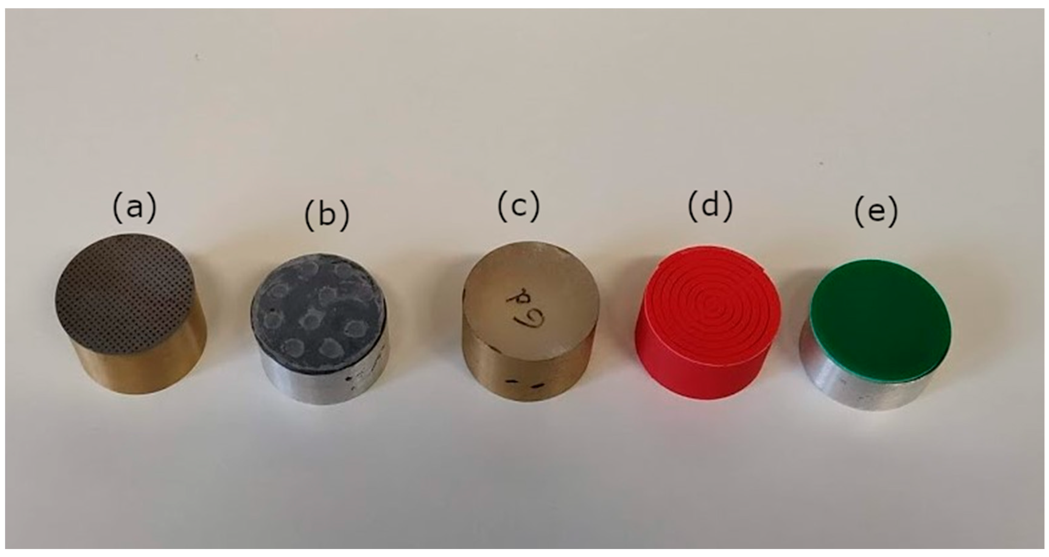
Figure 28 shows several MPPs manufactured in our laboratory using different techniques in chronological order. The five MPPs have a diameter of 28.5 mm and were machined to be measured in an impedance tube. Initially, MPPs were manufactured usually using laser technology (Figure 28a). This technology provides MPPs with accurate holes but is rather expensive, since it requires perforating a lot of minute holes on a hard surface. As described above, the MIU combined a carrying plate with larger holes with a micrometric mesh, commercial use of which is frequent in filtering applications (Figure 28b). Therefore, its manufacturing cost was much cheaper than the conventional MPP.
The cost could be further reduced with the infiltration technique described in Section 2.6. An MPP manufactured using an infiltration technique is displayed in Figure 28c. The cost of this technique is the same as that of the polymeric resin and the salt grains, hence much cheaper than that of the equivalent MPP machined by laser.
Figure 28d shows an MPP fabricated using 3D printing. In this case, the perforations were achieved using thin slits. This is another example of a rather cheap MPP, the cost of which is the same as the cost of the material used for printing.
Finally, a technique which allows perforation of very precise holes is borrowed from that employed in advanced circuitry applications by drilling epoxy laminates. An example of such an MPP is shown in Figure 28e. Compared with laser technology, the cost of this technique is roughly 20/300 euros. Cobo et al. [56] confirmed that it is possible to manufacture cheap TL-MPPs, optimized using simulated annealing, using this technique.
5. Conclusions
Sound absorbers based on MPPs were proposed as a good alternative to conventional porous/fibrous absorbers when cleanliness and health related aspects are of paramount importance. The mathematical bases for designing such absorbers were already posed by Maa in the last quarter of the 20th century. However, their development as large-scale absorbers has taken a lot of time, mainly due to two reasons: their low absorption bandwidth and high manufacturing cost. These limitations are now being overcome. Modern MPPs can be manufactured using 3D printing or by drilling epoxy laminates primarily used for advanced circuitry. The absorption bandwidth can be significantly increased by designing multiple-layer MPPs. Specifically, the sound absorption of an MPP can be increased from roughly two octaves, for a single-layer MPP, to more than three octaves, for a double-layer MPP, and more than four octaves, with a triple-layer MPP. These bandwidths are enough to cover most of the absorption needs in building acoustics.
Author Contributions
Conceptualization, methodology, and first draft preparation—P.C.; Conceptualization, methodology, and revision of first draft—F.S.
Funding
This research was funded by the Ministry of Science, Innovation and Universities through grant number DPI2016-79559R.
Acknowledgments
Fruitful discussions with C. de la Colina are acknowledged.
Conflicts of Interest
The authors declare no conflicts of interest.
References
- Cobo, P.; Ruiz, H.; Alvarez, J. Double-Layer Microperforated Panel/Porous absorber as liner for anechoic closing of the test section in wind tunnels. Acta Acust. United Acust. 2010, 96, 914–922. [Google Scholar] [CrossRef]
- Maa, D.Y. Microperforated-panel wideband absorbers. Noise Control Eng. J. 1987, 29, 77–84. [Google Scholar] [CrossRef]
- Maa, D.Y. Potential of microperforated panel absorber. J. Acoust. Soc. Am. 1998, 104, 2861–2866. [Google Scholar] [CrossRef]
- Allard, J.F. Propagation of Sound in Porous Media. Modelling Sound Absorbing Materials; Elsevier Applied Science: London, UK, 1993. [Google Scholar]
- Allard, J.F.; Atalla, N. Propagation of Sound in Porous Media. Modelling Sound Absorbing Materials; John Wiley & Sons: Chichester, West Sussex, UK, 2009. [Google Scholar]
- Atalla, N.; Sgard, J.F. Modeling of perforated plates and screens using rigid frame porous models. J. Sound Vib. 2007, 303, 195–208. [Google Scholar] [CrossRef]
- Ingard, U. On the theory and design of acoustic resonators. J. Acoust. Soc. Am. 1953, 25, 1037–1061. [Google Scholar] [CrossRef]
- Maa, D.Y. Theory of microslit absorbers. Chin. J. Acoust. 2001, 20, 1–10. [Google Scholar]
- Randeberg, R.T. Perforated Panel Absorbers with Viscous Energy Dissipation Enhanced by Orifice Design. Doctoral Thesis, Norweian University of Science and Technology, Trondheim, Norway, 2000. [Google Scholar]
- Vigran, T.O.; Pettersen, O.K.Ø. The absorption of slotted panels revisited. In Proceedings of the Forum Acusticum, Budapest, Hungary, 29 August–2 September 2005; pp. 2037–2040. [Google Scholar]
- Pfretzschner, J.; Cobo, P.; Simon, F.; Cuesta, M.; Fernández, A. Microperforated Insertion Units: an alternative strategy the design of microperforated panels. Appl. Acoust. 2006, 67, 62–73. [Google Scholar] [CrossRef]
- Ruiz, H.; Cobo, P.; Dupont, T.; Martin, B.; Leclaire, P.H. Acoustic properties of plates with unevenly distributed macroperforations backed by woven meshes. J. Acoust. Soc. Am. 2012, 132, 3138–3147. [Google Scholar] [CrossRef]
- Cobo, P.; Montero de Espinosa, F. A proposal of cheap microperforated panels manufactured by infiltration. Appl. Acoust. 2013, 74, 1069–1075. [Google Scholar] [CrossRef]
- Quian, Y.J.; Kong, D.Y.; Liu, S.M.; Sun, S.M.; Xhao, Z. Investigation on micro-perforated panel absorber with ultra-micro perforations. Appl. Acoust. 2013, 74, 931–935. [Google Scholar] [CrossRef]
- Lee, J.; Swenson, G.W., Jr. Compact sound absorbers for low frequencies. Noise Control Eng. J. 1992, 38, 109–117. [Google Scholar] [CrossRef]
- Lee, D.H.; Kwon, Y.P. Estimation of the absorption performance of multiple layer perforated panel systems by transfer matrix method. J. Sound Vib. 2004, 278, 847–860. [Google Scholar] [CrossRef]
- Cobo, P.; Cuesta, M.; Siguero, M. Comparison of models describing double layer microperforated absorbers. Noise Control Eng. J. 2009, 57, 10–15. [Google Scholar] [CrossRef]
- Liu, Z.; Zhan, J.; Fard, M.; Davy, J.L. Acoustic properties of multilayer sound absorbers with a 3D printed micro-perforated panel. Appl. Acoust. 2017, 121, 25–32. [Google Scholar] [CrossRef]
- Liu, Z.; Zhan, J.; Fard, M.; Davy, J.L. Acoustic measurement of a 3D printed micro-perforated panel combined with a porous material. Measurements 2017, 1041, 233–236. [Google Scholar] [CrossRef]
- Wang, Y.; Zhang, C.; Ren, L.; Ichchou, M.; Galland, M.A.; Bareille, O. Sound absorption of a new bionic multi-layer absorber. Compos. Struct. 2014, 108, 400–408. [Google Scholar] [CrossRef]
- Park, S.H. Acoustic properties of micro-perforated panel absorbers backed by Helmholtz resonators for the improvement of low-frequency sound absorption. J. Sound Vib. 2013, 332, 4895–4911. [Google Scholar] [CrossRef]
- Gai, X.-L.; Li, X.-H.; Tuo, B.Z.; Zhao, J.-J.; Ma, Z.-H. Experimental study on sound absorption performance of microperforated panel with membrane cell. Appl. Acoust. 2016, 110, 241–247. [Google Scholar] [CrossRef]
- Duan, X.H.; Wang, H.Q.; Li, Z.B.; Zhu, L.K.; Chen, R.; Kong, D.Y.; Zhao, Z. Sound absorption of a flexible micro-perforated panel absorber based on PVDF piezoelectric film. Appl. Acoust. 2015, 88, 84–89. [Google Scholar] [CrossRef]
- Guo, W.; Min, H. A compound micro-perforated panel sound absorber with partitioned cavities of different depths. Energy Procedia 2015, 78, 1617–1622. [Google Scholar] [CrossRef]
- Huang, S.; Li, S.; Wang, X.; Mao, D. Micro-perforated absorbers with incompletely partitioned cavities. Appl. Acoust. 2017, 126, 114–119. [Google Scholar] [CrossRef]
- Quian, Y.J.; Kong, D.Y.; Liu, Y.; Liu, S.M.; Li, Z.B.; Shao, D.S.; Sun, S.M. Improvement of sound absorption characteristics under low frequency for micro-perforated panel absorbers using super-aligned carbon nanotube arrays. Appl. Acoust. 2014, 82, 23–27. [Google Scholar] [CrossRef]
- Xiaodan, Z.; Xiangqian, F. Enhancing low frequency sound absorption of micro-perforated panel absorbers by using mechanical impedance plates. Appl. Acoust. 2015, 88, 123–128. [Google Scholar]
- Xiaodan, Z.; Wang, X.; Yongjie, Y. Enhancing low-frequency sound absorption of micro-perforated panel absorbers by combining parallel mechanical impedance. Appl. Acoust. 2018, 130, 300–304. [Google Scholar]
- Kim, B.S.; Cho, S.J.; Min, D.K.; Park, J. Sound absorption structure in helical shapes made using fibrous paper. Compos. Struct. 2015, 134, 90–94. [Google Scholar] [CrossRef]
- Kim, B.S.; Cho, S.J.; Min, D.K.; Park, J. Experimental study for improving sound absorption of a composite helical-shaped porous structure using carbon fiber. Compos. Struct. 2016, 145, 242–247. [Google Scholar] [CrossRef]
- Onen, O.; Caliskan, M. Design of a single layer micro-perforated sound absorber by finite element analysis. Appl. Acoust. 2010, 71, 79–85. [Google Scholar] [CrossRef]
- Carbajo, J.; Ramis, J.; Godinho, L.; Amado-Mendes, P.; Alba, J. A finite element model of perforated panel absorbers including viscothermal effects. Appl. Acoust. 2015, 90, 1–8. [Google Scholar] [CrossRef]
- Ruiz, H.; Cobo, P.; Jacobsen, F. Optimization of multiple-layer microperforated panels by simulated aneealing. Appl. Acoust. 2011, 72, 772–776. [Google Scholar] [CrossRef]
- Cobo, P.; Moraes, E.; Simon, F. Inverse estimation of the non-acoustical parameters of loose granular absorbers by Simulated Annealing. Build. Environ. 2015, 94, 859–866. [Google Scholar] [CrossRef]
- Cobo, P.; Simon, F. A comparison of impedance models for the inverse estimation of the non-acoustical parameters of granular absorbers. Appl. Acoust. 2016, 104, 119–126. [Google Scholar] [CrossRef]
- Cobo, P.; Simon, F. Using simulating annealing for the inverse estimation of the non-acoustical parameters of sound absorbers. Build. Acoust. 2017, 24, 295–306. [Google Scholar] [CrossRef]
- Jaouen, L.; Becot, F.X. Acoustical characterization of perforated facings. J. Acoust. Soc. Am. 2011, 129, 1400–1406. [Google Scholar] [CrossRef] [PubMed]
- Tayong, R.; Leclaire, P. Hole interaction effects under high and medium sound intensities for micro-perforated panels design. In Proceedings of the 10éme Congress Francais d’Acoustique, Lyon, France, 12–16 April 2010. [Google Scholar]
- Cobo, P. Absorción del Sonido; Biblioteca de Ciencias, 42, CSIC: Madrid, Spain, 2015. [Google Scholar]
- Fahy, F. Foundations of Engineering Acoustics; Academicc Press: San Diego, CA, USA, 2001. [Google Scholar]
- Hou, K. Measurement and Modeling of Micro-Perforated Panels. Master’s Thesis, Purdue University, West Lafayette, IN, USA, 2009. [Google Scholar]
- Melling, T.H. The acoustic impedance of perforates at medium and high sound pressure levels. J. Sound Vib. 1973, 29, 1–65. [Google Scholar] [CrossRef]
- Rschevkin, S.N. A Course of Lectures on the Theory of Sound; Pergamon Press: Oxford, UK, 1963. [Google Scholar]
- Stinson, M.R.; Champoux, Y. Propagation of sound and the assignment of shape factors in models of porous materials having simple geometries. J. Acoust. Soc. Am. 1992, 91, 685–695. [Google Scholar] [CrossRef]
- Cobo, P.; Pfretszchner, J.; Cuesta, M.; Anthony, D.K. Hybrid passive-active absorption using microperforated panels. J. Acoust. Soc. Am. 2004, 116, 2118–2125. [Google Scholar] [CrossRef]
- Cobo, P.; Fernández, A. Hybrid passive-active absorption of broadband noise using MPPs. Noise Vib. Worldw. 2006, 37, 19–23. [Google Scholar] [CrossRef]
- Cobo, P.; Cuesta, M. Hybrid passive-active absorption of a microperforated panel in free field conditions. J. Acoust. Soc. Am. 2007, 121, EL251–EL255. [Google Scholar] [CrossRef]
- Cobo, P.; Cuesta, M. Measuring hybrid passive-active sound absorption of a microperforated liner at oblique incidence. J. Acoust. Soc. Am. 2009, 125, 185–190. [Google Scholar] [CrossRef]
- Mechel, F.P.; Ver, I.L. Sound absorbing materials and sound absorbers. In Noise and Vibration Control Engineering; Beranek, L.L., Ver, I.L., Eds.; John Wiley & Sons: New York, NY, USA, 1992. [Google Scholar]
- Ortiz, S.; González, C.; Cobo, P.; Montero de Espinosa, F. Attenuating open cavity tones by lining its walls with microperforated panels. Noise Control Eng. J. 2014, 62, 145–151. [Google Scholar] [CrossRef]
- Mechel, F.P. Formulas of Acoustics; Spriger: Berlin, Germany, 2002. [Google Scholar]
- Morfey, C.L. Dictionary of Acoustics; Academic Press: London, UK, 2001. [Google Scholar]
- Cox, T.J.; D’Antonio, P. Acoustic Absorbers and Diffusers. Theory, Design, and Application; Spon Press: New York, NY, USA, 2004. [Google Scholar]
- Ingard, U. Notes on Sound Absorption; Kittery Point: Kittery, ME, USA, 1999. [Google Scholar]
- Kang, J.; Fuchs, H.V. Predicting the sound absorption of open weave textiles and microperforated membranes backed by an air space. J. Sound Vib. 1999, 220, 905–920. [Google Scholar] [CrossRef]
- Cobo, P.; de la Colina, C.; Roibás, E.; Chimeno, M.; Simón, F. A wideband triple-layer microperforated panel sound absorber. Compos. Struct. 2019. submitted. [Google Scholar]
Figure 1.
Sketch of a single-layer microperforated panel (SL-MPP).

Figure 2.
Relationship between the particle velocity inside, u, and outside, u’, the perforations of an MPP.
Figure 2.
Relationship between the particle velocity inside, u, and outside, u’, the perforations of an MPP.
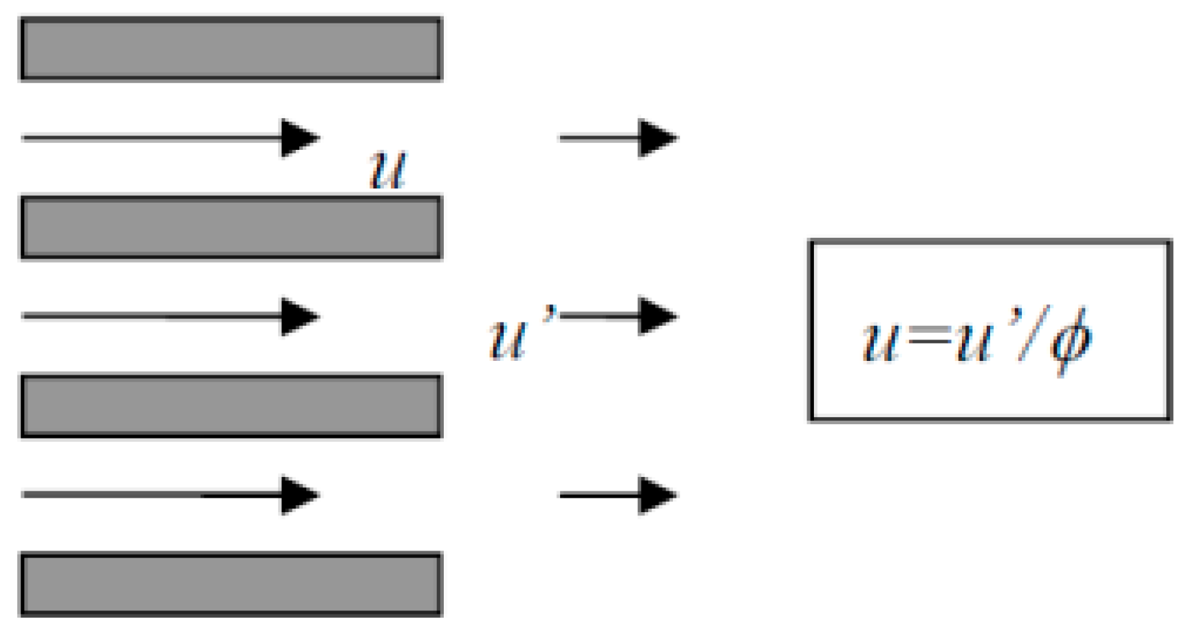
Figure 3.
Mass reactance due to the excess of vibrating mass in the hole edges.

Figure 4.
Meaning of b and d in the definition of for the Fok function.

Figure 5.
Graphical representation of the Fok function.
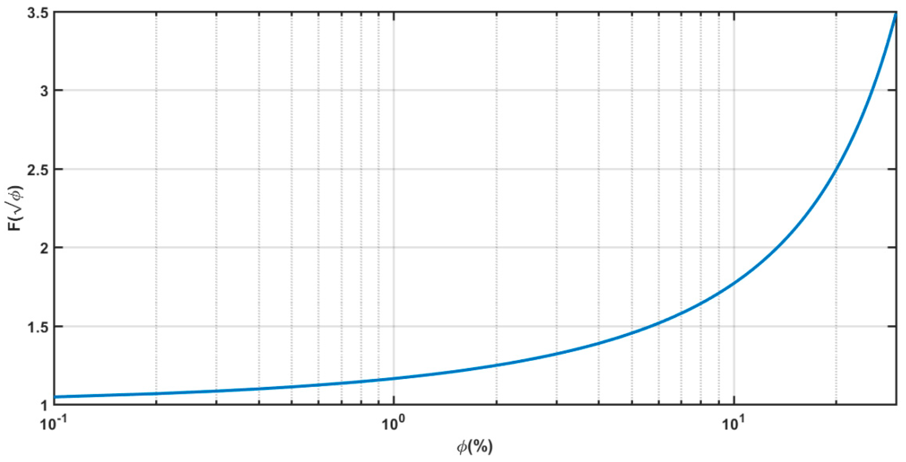
Figure 6.
Absorption coefficient of an SL-MPP as a function of (f,d) for (t,ϕ,D) = (1 mm,1%,2 cm).
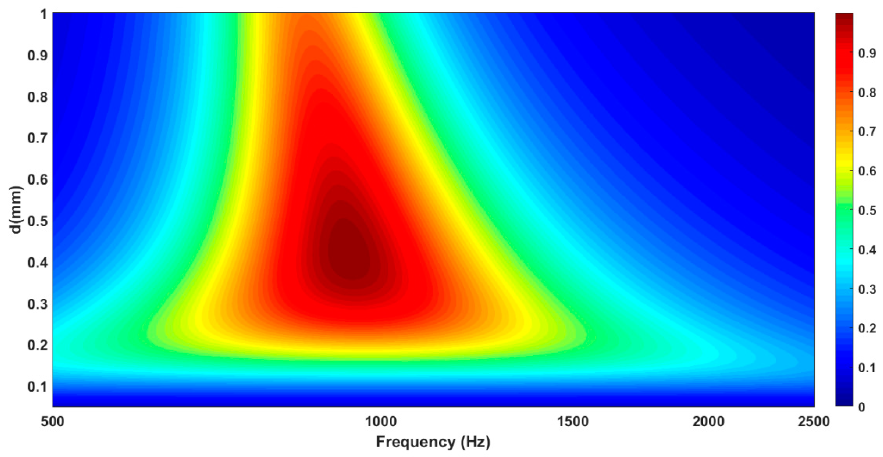
Figure 7.
Absorption coefficient of an SL-MPP as a function of (f,t) for (d,ϕ,D) = (0.4 mm,1%,2 cm).
Figure 7.
Absorption coefficient of an SL-MPP as a function of (f,t) for (d,ϕ,D) = (0.4 mm,1%,2 cm).
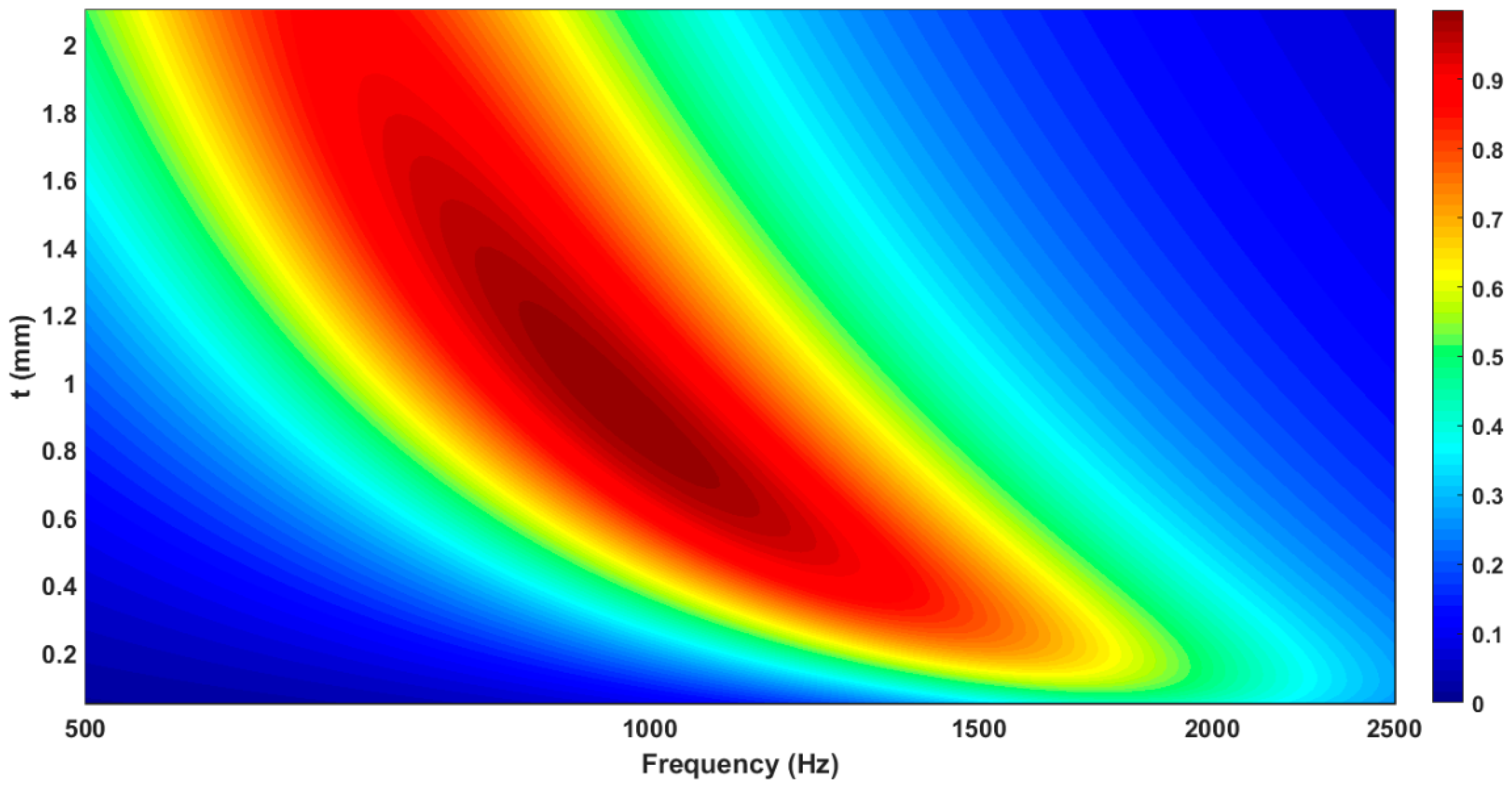
Figure 8.
Absorption coefficient of an SL-MPP as a function of (f,ϕ) for (d,t,D) = (0.4 mm,1 mm,2 cm).
Figure 8.
Absorption coefficient of an SL-MPP as a function of (f,ϕ) for (d,t,D) = (0.4 mm,1 mm,2 cm).

Figure 9.
Absorption coefficient of an SL-MPP as a function of (f,D) for (d,t,ϕ) = (0.4 mm,1 mm,1%).
Figure 9.
Absorption coefficient of an SL-MPP as a function of (f,D) for (d,t,ϕ) = (0.4 mm,1 mm,1%).

Figure 10.
Absorption coefficient of an SL-MPP as a function of (d,t) for (f,ϕ,D) = (1500 Hz,1%,2 cm).
Figure 10.
Absorption coefficient of an SL-MPP as a function of (d,t) for (f,ϕ,D) = (1500 Hz,1%,2 cm).

Figure 11.
Absorption coefficient of an SL-MPP with t = 0.5 mm, D = 2 cm and different values of d and ϕ.
Figure 11.
Absorption coefficient of an SL-MPP with t = 0.5 mm, D = 2 cm and different values of d and ϕ.

Figure 12.
Overperforation correction factors by Fok function and tortuosity.

Figure 13.
Absorption curves provided by the Maa (solid line) and EF (dotted line) models for D = 3 cm and different combinations of the parameters (d,t,ϕ).
Figure 13.
Absorption curves provided by the Maa (solid line) and EF (dotted line) models for D = 3 cm and different combinations of the parameters (d,t,ϕ).

Figure 14.
Sketch of a panel microperforated with (a) circular holes and (b) slits.
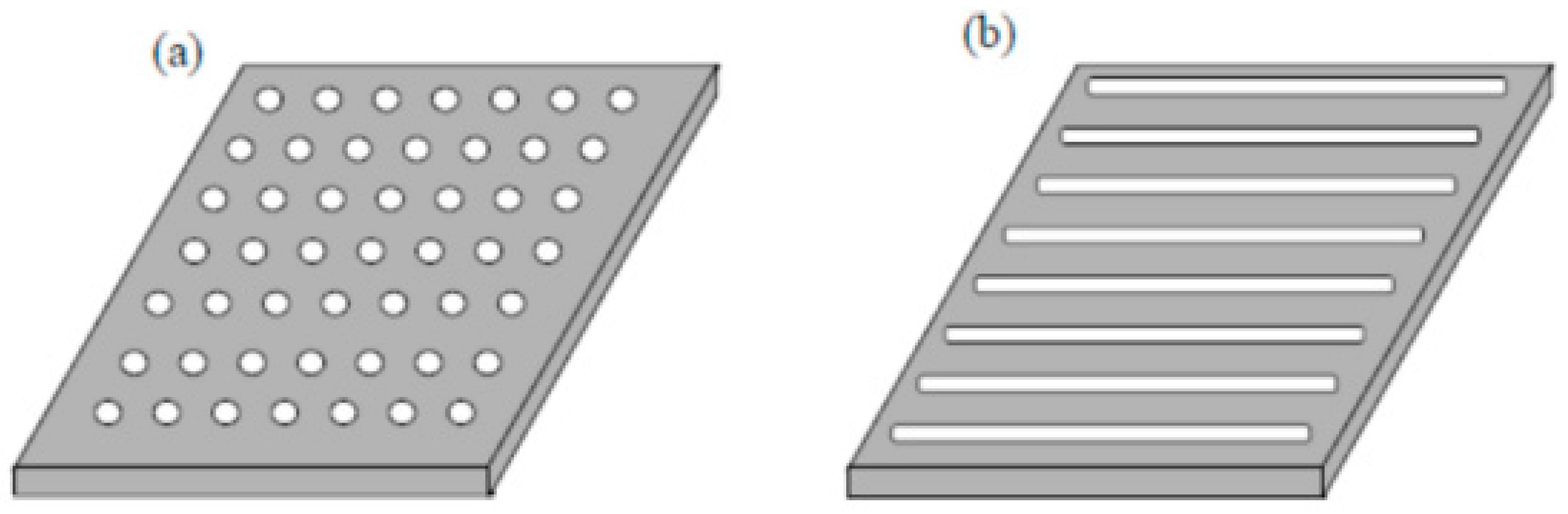
Figure 15.
Comparison of the absorption curves of an SL-MSP and an equivalent SL-MPP for (d,t,ϕ,D) = (0.15 mm,1 mm,5%,5 cm).
Figure 15.
Comparison of the absorption curves of an SL-MSP and an equivalent SL-MPP for (d,t,ϕ,D) = (0.15 mm,1 mm,5%,5 cm).
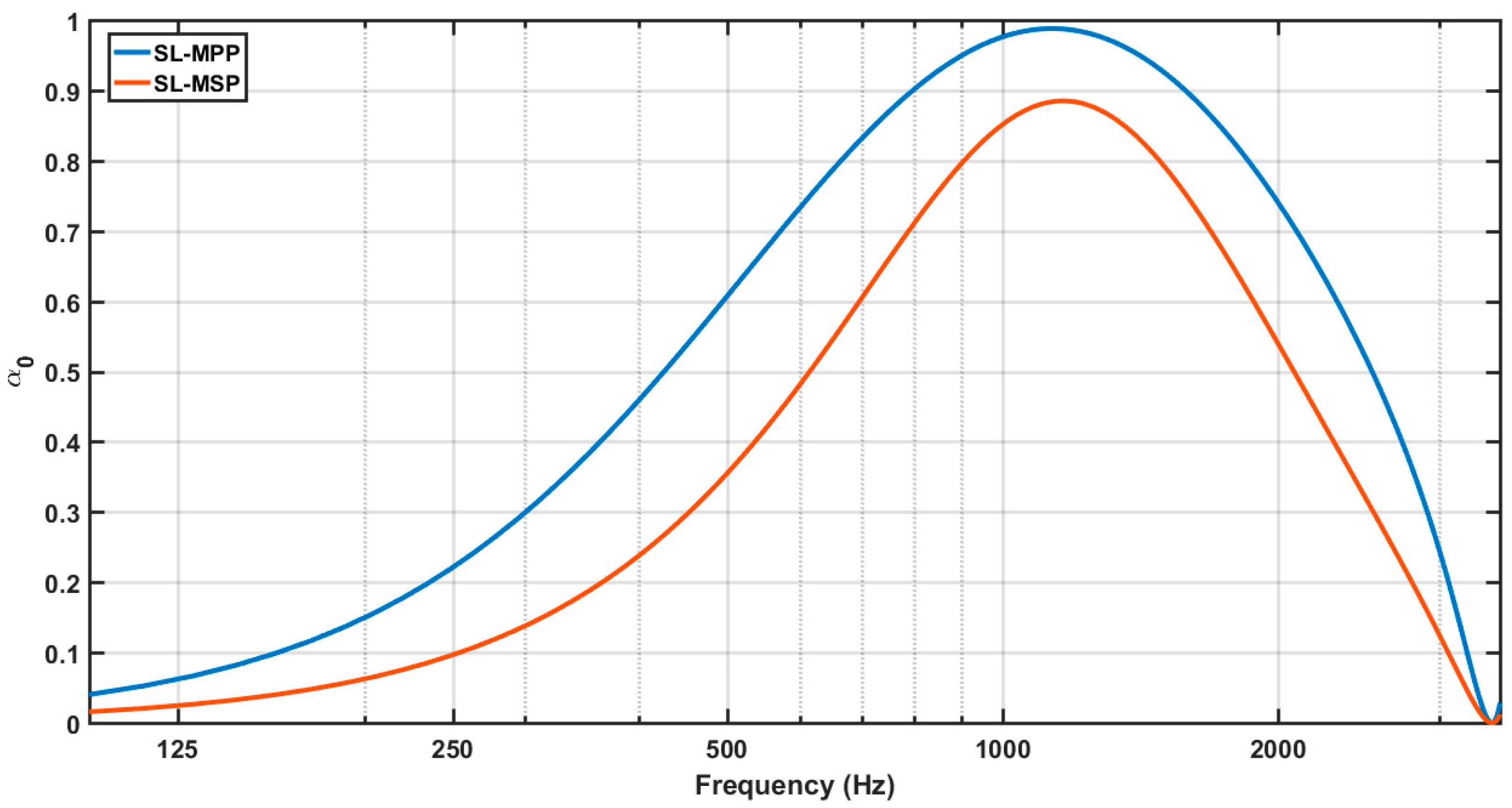
Figure 16.
Absorption curves of an SL-MSP (red lines) and the equivalent SL-MPP (blue lines) for D = 5 cm and (a) (d,t,ϕ) = (0.5 mm,0.5 mm,0.5%), (b) (d,t,ϕ) = (0.25 mm,0.75 mm,1%), (c) (d,t,ϕ) = (0.15 mm,1 mm,5%), and (d) (d,t,ϕ) = (0.1 mm,1.13 mm,10%).
Figure 16.
Absorption curves of an SL-MSP (red lines) and the equivalent SL-MPP (blue lines) for D = 5 cm and (a) (d,t,ϕ) = (0.5 mm,0.5 mm,0.5%), (b) (d,t,ϕ) = (0.25 mm,0.75 mm,1%), (c) (d,t,ϕ) = (0.15 mm,1 mm,5%), and (d) (d,t,ϕ) = (0.1 mm,1.13 mm,10%).

Figure 17.
Sketch of the MIU design. Two single MPPs, the carrying plate and the micrometric mesh, are used to form the MIU. The horizontal arrow above the micrometric mesh means that it is moved to bond the carrying plate.
Figure 17.
Sketch of the MIU design. Two single MPPs, the carrying plate and the micrometric mesh, are used to form the MIU. The horizontal arrow above the micrometric mesh means that it is moved to bond the carrying plate.

Figure 18.
Boundary conditions at the MIU interface.
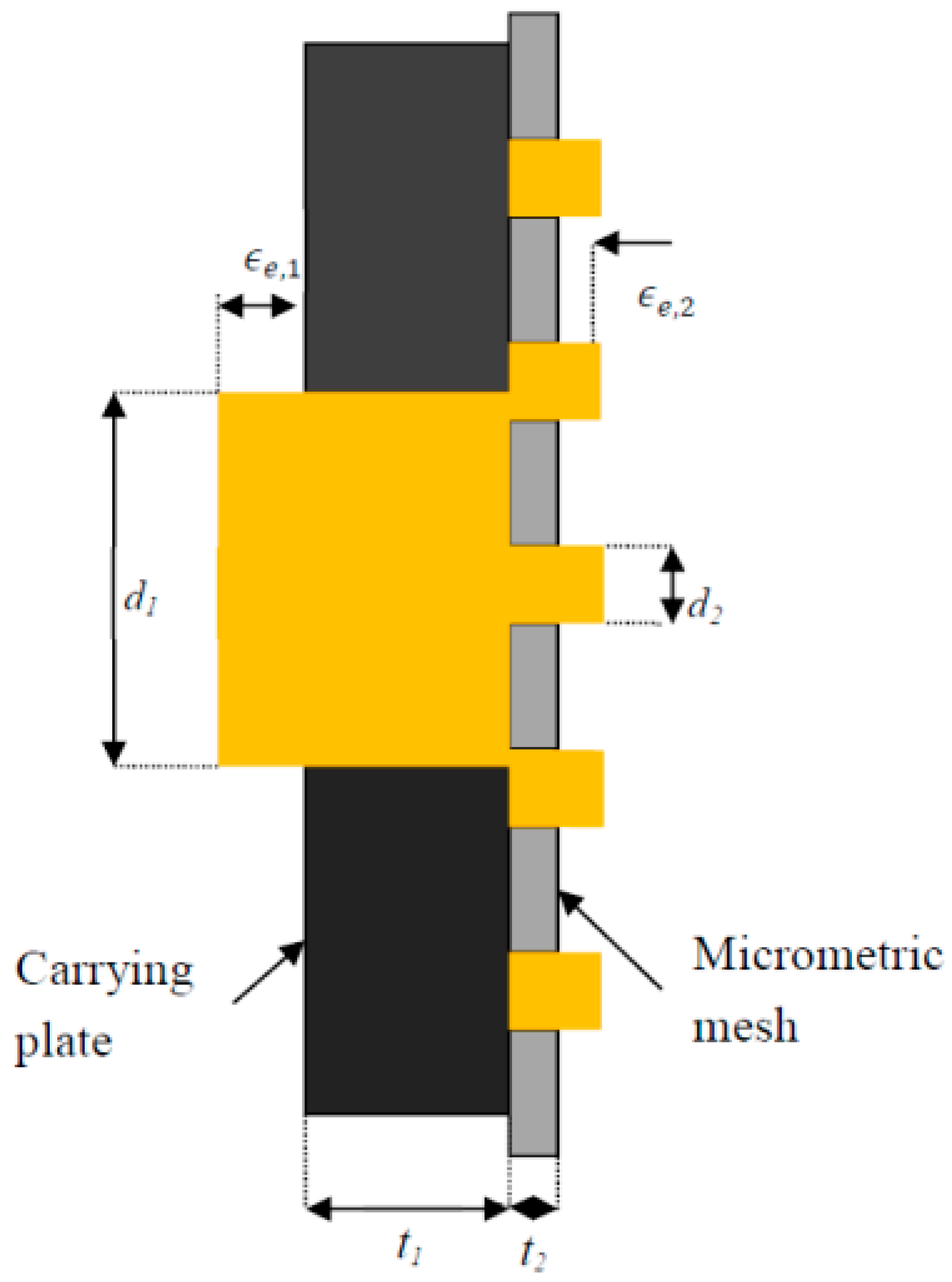
Figure 19.
Absorption curves of an SL-MIU with hole perforations, according to the Maa and EF models for (d1,t1,ϕ1,d2,t2,ϕ2,D) = (3 mm,1 mm,10%,41 μm,50 μm,31%,3 cm).
Figure 19.
Absorption curves of an SL-MIU with hole perforations, according to the Maa and EF models for (d1,t1,ϕ1,d2,t2,ϕ2,D) = (3 mm,1 mm,10%,41 μm,50 μm,31%,3 cm).
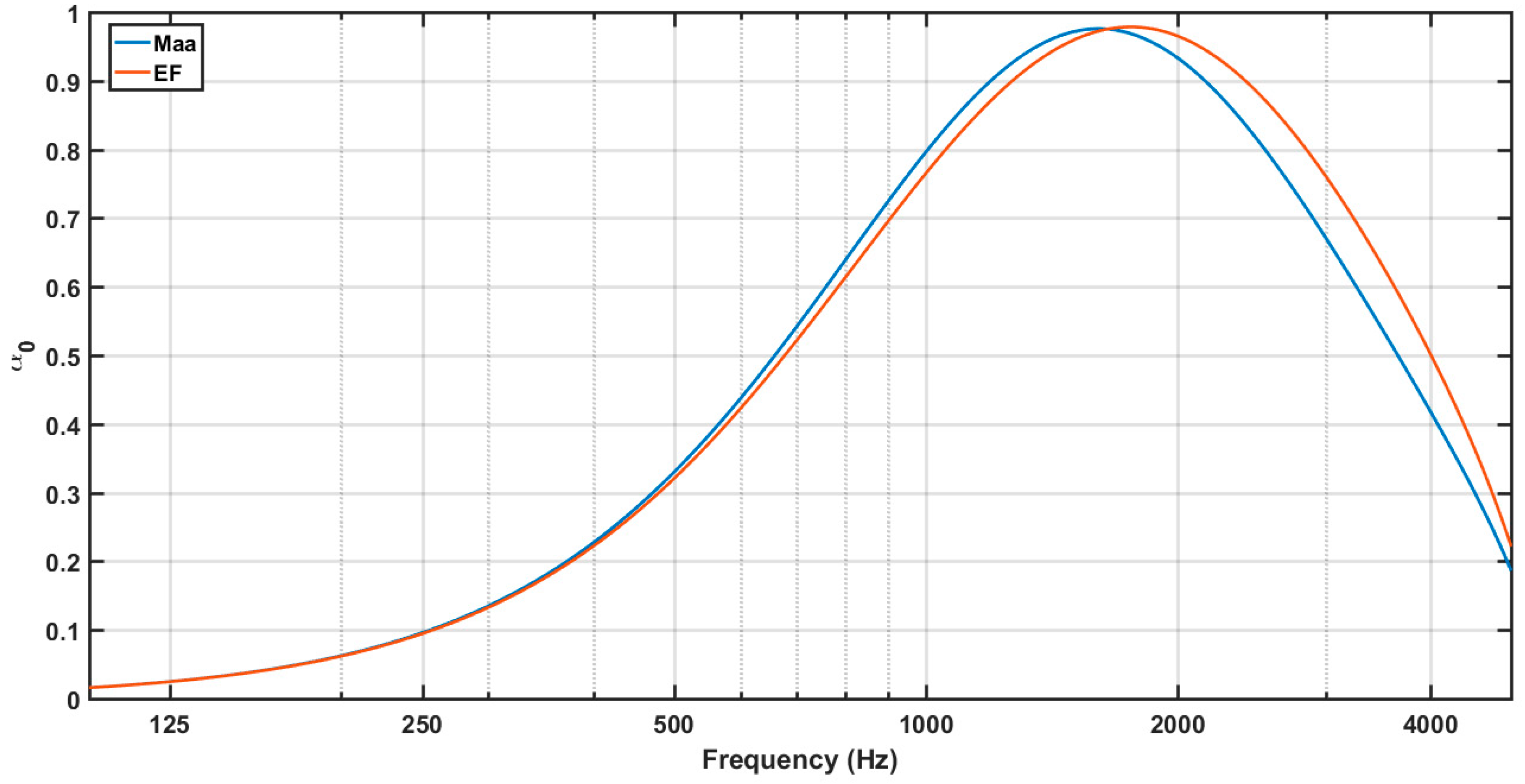
Figure 20.
Sketch of an MPP with (a) evenly distributed regular size holes and (b) irregular holes unevenly distributed.
Figure 20.
Sketch of an MPP with (a) evenly distributed regular size holes and (b) irregular holes unevenly distributed.

Figure 21.
Measured absorption curves of the SL-MPP absorber manufactured using infiltration in comparison with those provided by the modified Maa and EF models.
Figure 21.
Measured absorption curves of the SL-MPP absorber manufactured using infiltration in comparison with those provided by the modified Maa and EF models.

Figure 22.
Absorption coefficients at normal ) and random incidence for local () and bulk () reaction of an SL-MPP with parameters (d,t,ϕ,D) = (0.1 mm,0.1 mm,1.8%,4 cm).
Figure 22.
Absorption coefficients at normal ) and random incidence for local () and bulk () reaction of an SL-MPP with parameters (d,t,ϕ,D) = (0.1 mm,0.1 mm,1.8%,4 cm).

Figure 23.
Normal incidence absorption coefficient of an SL-MPP with d = 0.12 mm, t = 1 mm, ϕ= 10%, and D = 2 cm.
Figure 23.
Normal incidence absorption coefficient of an SL-MPP with d = 0.12 mm, t = 1 mm, ϕ= 10%, and D = 2 cm.

Figure 24.
Sketch of a DL-MPP at normal incidence.

Figure 25.
Normal incidence absorption coefficient of a DL-MPP with (d1,t1,ϕ1,D1,d2 t2,ϕ2,D2) = (0.15 mm,1 mm,10%,2 cm,0.15 mm,1 mm,15%,2 cm).
Figure 25.
Normal incidence absorption coefficient of a DL-MPP with (d1,t1,ϕ1,D1,d2 t2,ϕ2,D2) = (0.15 mm,1 mm,10%,2 cm,0.15 mm,1 mm,15%,2 cm).

Figure 26.
Sketch of a TL-MPP at normal incidence.

Figure 27.
Normal incidence absorption coefficient of a TL-MPP with parameters (d1,t1,ϕ1,D1,d2,t2,ϕ2,D2,d3,t3,ϕ3,D3) = (0.15 mm,1.35,15%,0.89 cm,0.15 mm,1.4 mm,10%,1.3 cm,0.15 mm,1.1 mm,5%,2 cm).
Figure 27.
Normal incidence absorption coefficient of a TL-MPP with parameters (d1,t1,ϕ1,D1,d2,t2,ϕ2,D2,d3,t3,ϕ3,D3) = (0.15 mm,1.35,15%,0.89 cm,0.15 mm,1.4 mm,10%,1.3 cm,0.15 mm,1.1 mm,5%,2 cm).

Figure 28.
Several MPPs of diameter 28.5 mm, manufactured using distinct techniques. (a) Laser technology, (b) MIU, (c) infiltration technique, (d) 3D printing, and (e) drilling an epoxy laminate.
Figure 28.
Several MPPs of diameter 28.5 mm, manufactured using distinct techniques. (a) Laser technology, (b) MIU, (c) infiltration technique, (d) 3D printing, and (e) drilling an epoxy laminate.
© 2019 by the authors. Licensee MDPI, Basel, Switzerland. This article is an open access article distributed under the terms and conditions of the Creative Commons Attribution (CC BY) license (http://creativecommons.org/licenses/by/4.0/).
Share and Cite
MDPI and ACS Style
Cobo, P.; Simón, F. Multiple-Layer Microperforated Panels as Sound Absorbers in Buildings: A Review. Buildings 2019, 9, 53. https://doi.org/10.3390/buildings9020053
AMA Style
Cobo P, Simón F. Multiple-Layer Microperforated Panels as Sound Absorbers in Buildings: A Review. Buildings. 2019; 9(2):53. https://doi.org/10.3390/buildings9020053
Chicago/Turabian StyleCobo, Pedro, and Francisco Simón. 2019. "Multiple-Layer Microperforated Panels as Sound Absorbers in Buildings: A Review" Buildings 9, no. 2: 53. https://doi.org/10.3390/buildings9020053
Note that from the first issue of 2016, this journal uses article numbers instead of page numbers. See further details here.