Sustainable Multi-Modal Sensing by a Single Sensor Utilizing the Passivity of an Elastic Actuator

Abstract
:1. Introduction
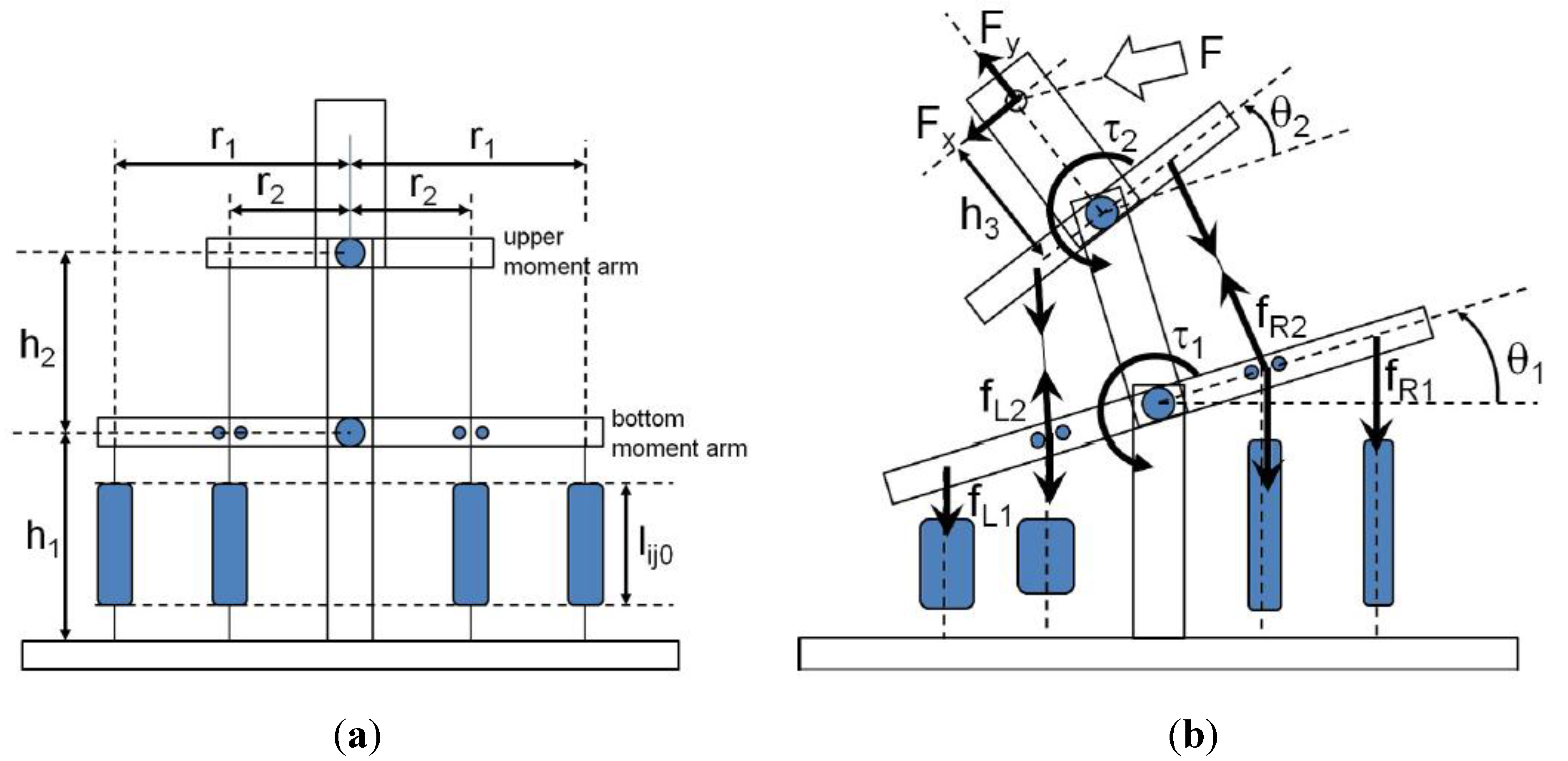
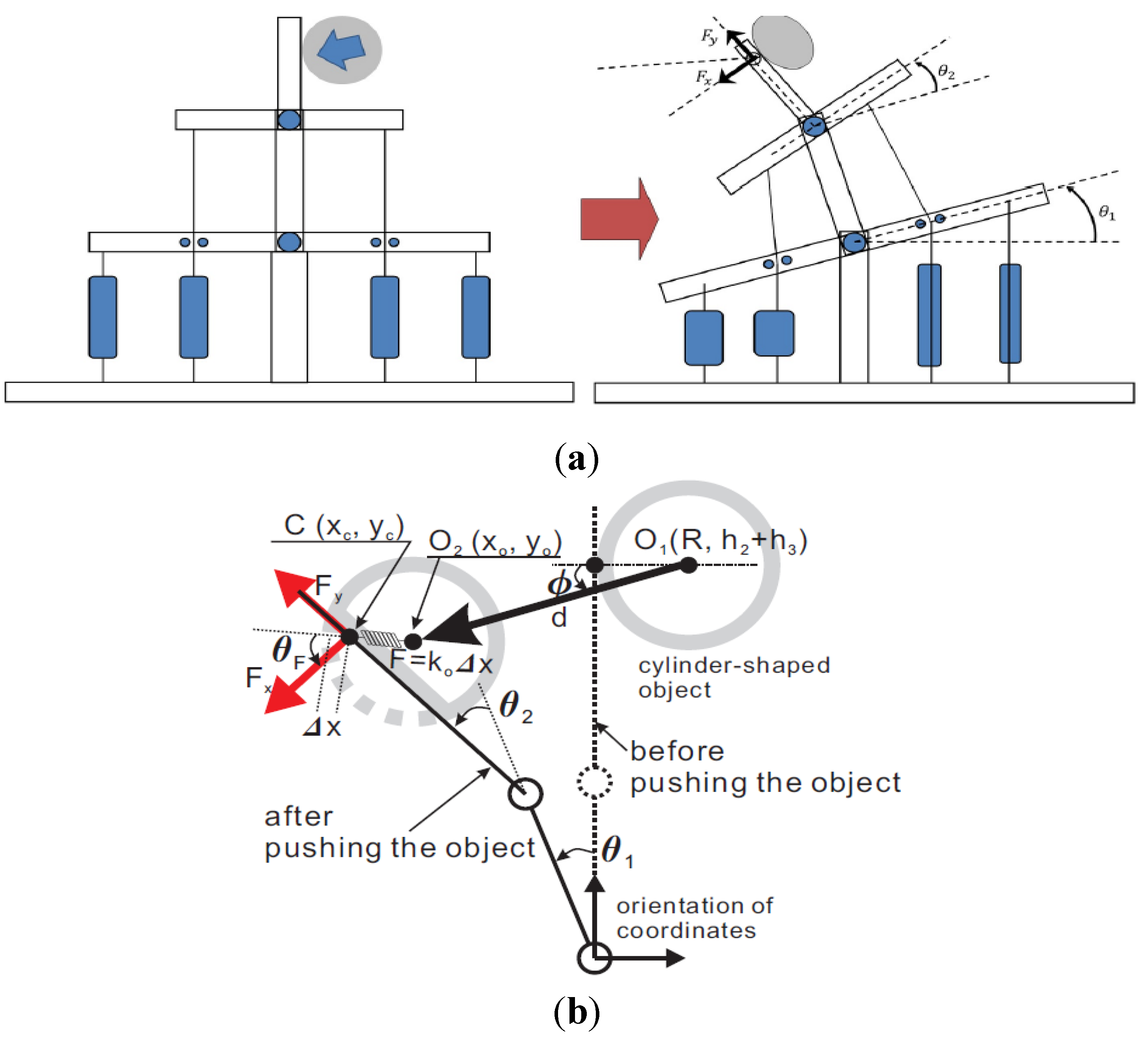
2. Relationship between the Contact Information and the Pressure
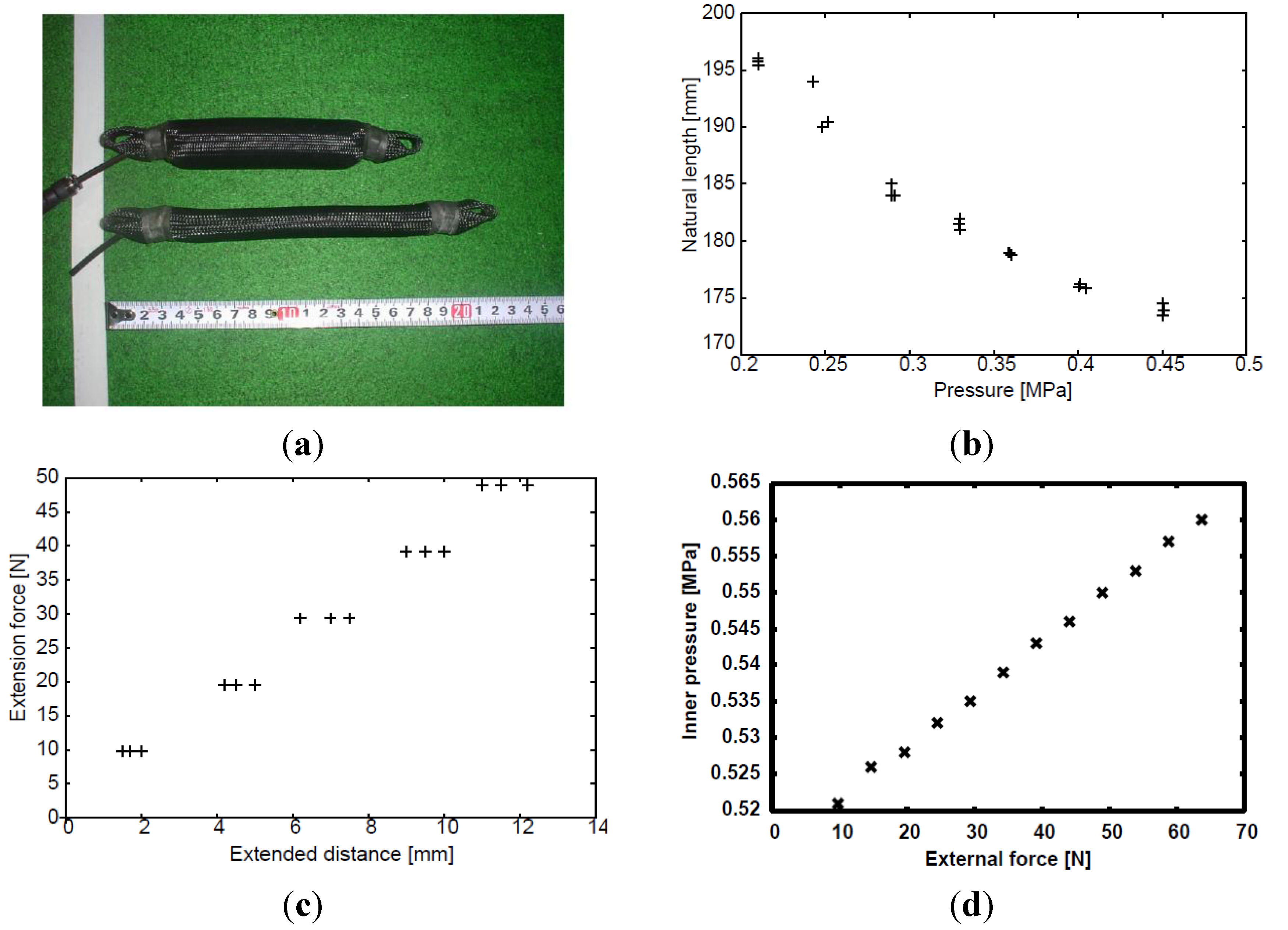
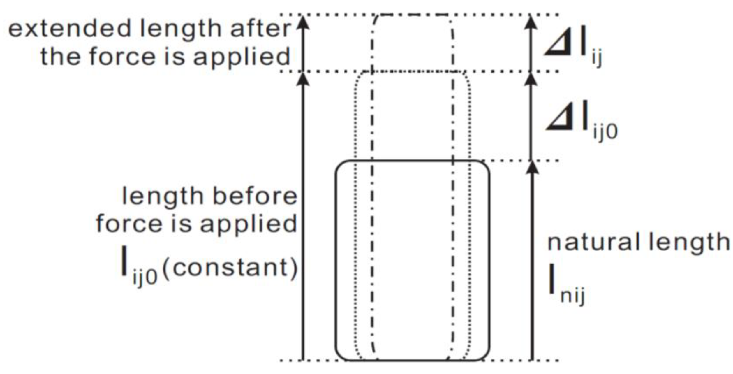
2.1. Passivity of the Pneumatic Actuator
2.2. Contact Information Using Actuator Pressures

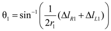
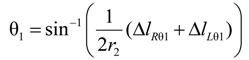
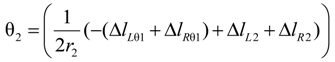
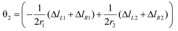
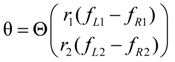
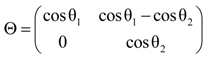
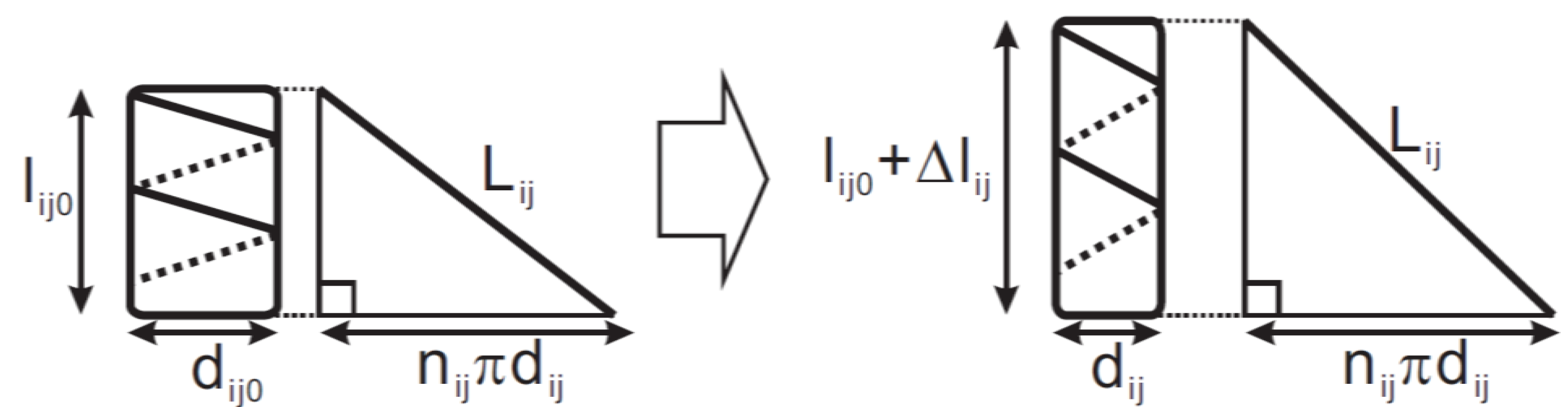
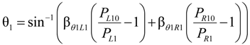
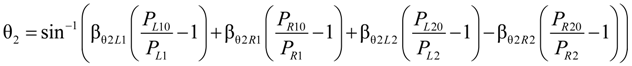
2.2.1. Joint Angle Using Extended Length
lsi2 + li20 = lsi2 + lni2 + Δli20 = h1 + h2
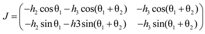
2.2.2. Applied Force Using Extended Length
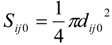
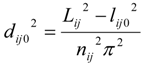
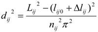
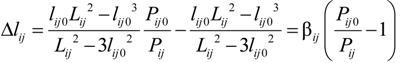
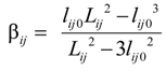
2.2.3. Extended Length Using Pressures

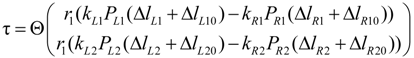
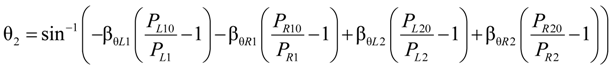
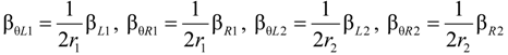
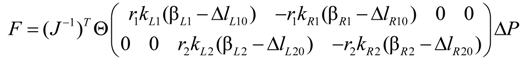
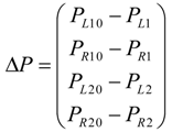
2.2.4. Contact Information Using Pressures


βF4 = −r2kR2(βR2 − ΔlR20), βF5 = r2kL2(βL2 − ΔlL20), βF6 = −r2kR2(βR2 − ΔlR20)
3. Experiments
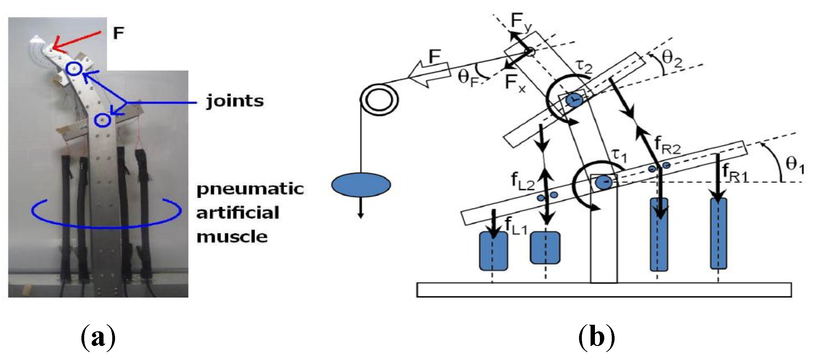
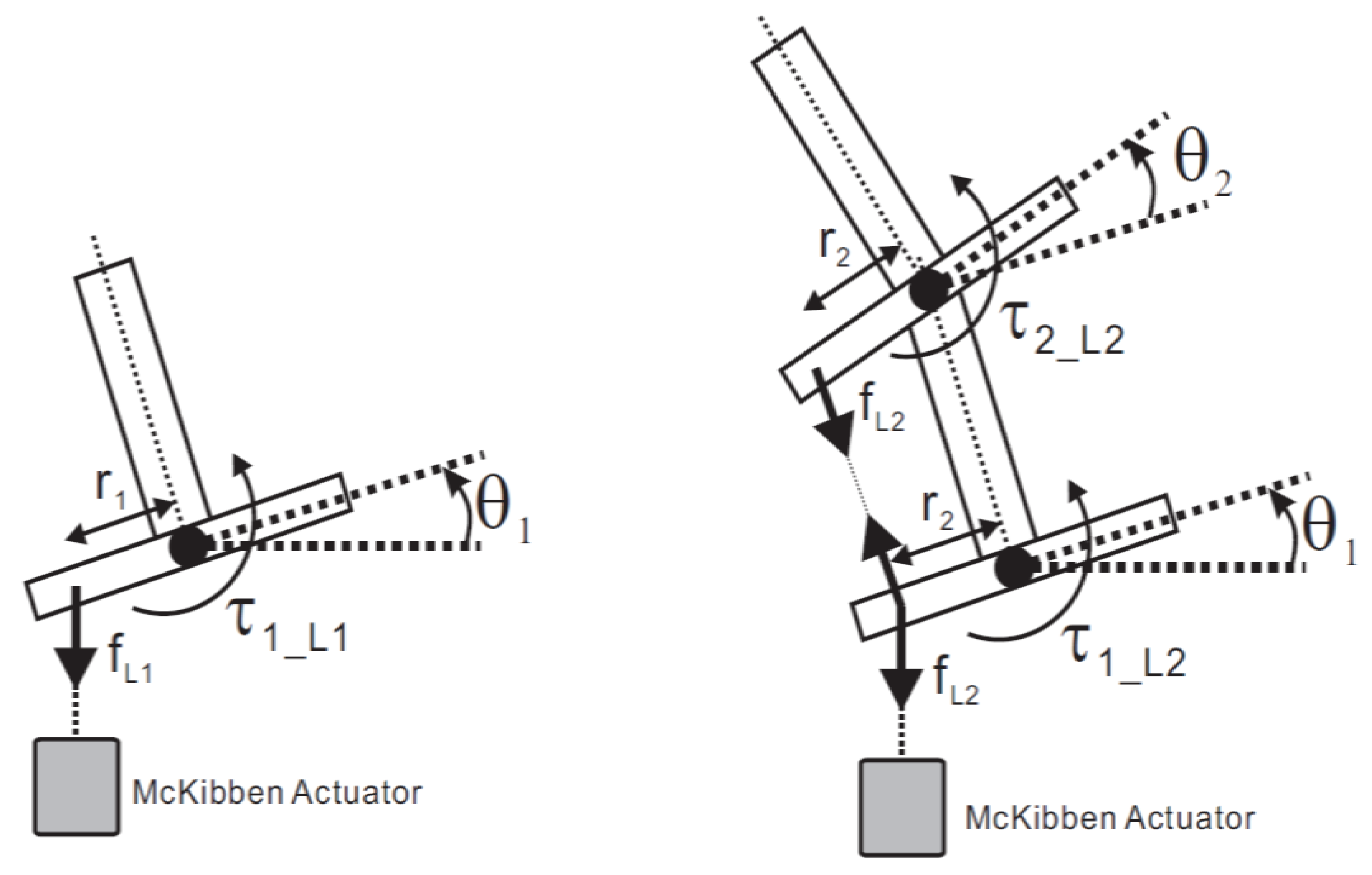
3.1. Developed 2-DoF Joint Mechanism

3.2. Experimental Setup
- Supplying compressed air. Compressed air is supplied to the actuators. The pressures Pij0 are measured by the pressure sensor;
- Applying an external force. The force F is applied to the contact point. In order to apply forces of various magnitudes and directions, a weight is suspended from a movable pulley, as shown in Figure 6b. The direction of the force is varied by moving the pulley;
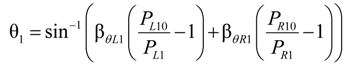
- Measuring contact information and pressure; After a certain interval of time subsequent to applying a force, the joint mechanism adopts an equilibrium posture. The angles θ1, θ2, the forces Fx, Fy, and the pressures Pij are subsequently recorded.


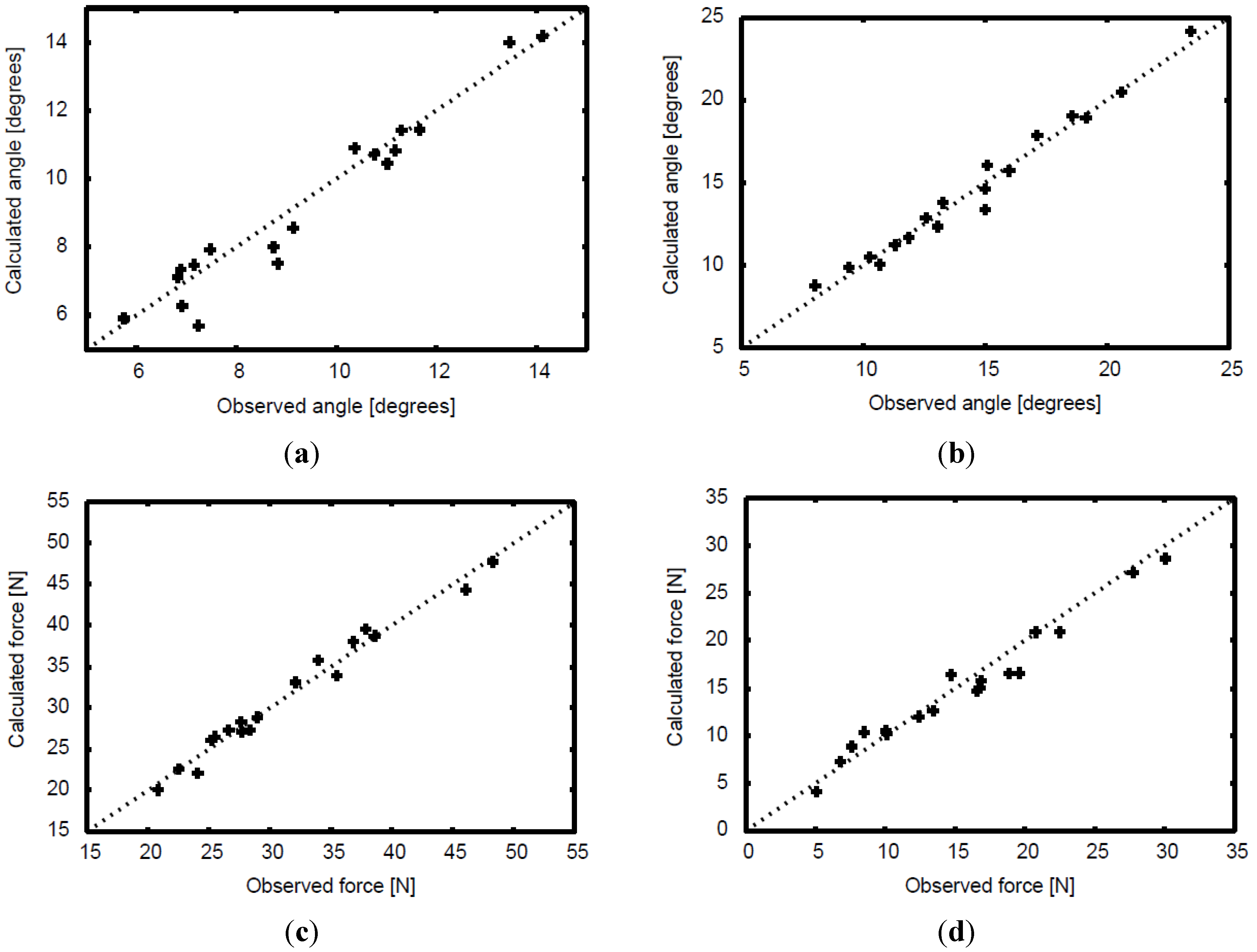
3.3. Result
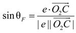
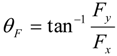
4. Application

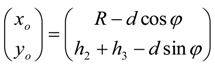
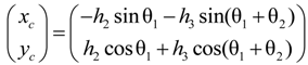
 can be expressed as
5. Conclusions
Author Contributions
Conflicts of Intrest
References
- Dollar, A.M.; Howe, R.D. The SDM hand: A highly adaptive compliant grasper for unstructured environments. In Experimental Robotics; Springer: Berlin, Germany, 2009; Volume 54, pp. 3–11. [Google Scholar]
- Iwata, H.; Sugano, S. Design of human symbiotic robot TWENDY-ONE. In Proceedings of the 2009 IEEE/RSJ International Conference on Robotics and Automation, Kobe, Japan, 12–17 May 2009; pp. 580–586.
- Yoshikawa, T.; Koeda, M.; Fujimoto, H. Shape recognition and grasping by robotic hands with soft fingers and omnidirectional camera. In Proceedings of the 2008 IEEE International Conference on Robotics and Automation, Pasadena, CA, USA, 19–23 May 2008; pp. 299–304.
- Raibert, M.H. Legged Robots That Balance; MIT Press: Cambridge, MA, USA, 1986. [Google Scholar]
- Takuma, T.; Hayashi, S.; Hosoda, K. 3D bipedal robot with tunable leg compliance mechanism for multi-modal locomotion. In Proceedings of the 2008 IEEE/RSJ International Conference on Intelligent Robots and Systems, Nice, France, 22–26 September 2008; pp. 1097–1102.
- Kimura, H.; Fukuoka, Y. Biologically inspired adaptive dynamic walking in outdoor environment using a self-contained quadruped robot “Tekken2”. In Proceedings of the IEEE/RSJ International Conference on Intelligent Robots and Systems, Sendai, Japan, 28 September–2 October 2004; Volume 1, pp. 986–991.
- Tsai, C.H.D.; Kao, I.; Sakamoto, N.; Higashimori, M. Applying viscoelastic contact modeling to grasping task: An experimental case study. In Proceedings of the 2008 IEEE/RSJ International Conference on Intelligent Robots and Systems, Nice, France, 22–26 September 2008; pp. 1790–1795.
- Weis, K.; Wörn, H. The working principle of resistive tactile sensor cells. In Proceedings of the IEEE International Conference on Mechatronics and Automation, Niagara falls, ON, Canada, 29 July–1 August 2005; Volume 1, pp. 471–476.
- Sun, Y.; Nelson, B.J.; Potasek, D.P.; Enikov, E. A bulk microfabricated multi-axis capacitive cellular force sensor using transverse comp drives. J. Micromechan. Microeng. 2002, 12, 832–840. [Google Scholar] [CrossRef]
- Luca, A.D.; Schäffer, A.A.; Haddadin, S.; Hirzinger, G. Collision detection and safe reaction with the DLR-III lightweight manipulator arm. In Proceedings of the 2006 IEEE/RSJ International Conference on Intelligent Robots and Systems, Beijing, China, October 2006; pp. 1623–1630.
- Stolt, A.; Linderoth, M.; Robertsson, A.; Johansson, R. Force Controlled Robotic Assembly without a Force Sensor. In Proceedings of the 2012 IEEE International Conference on Robotics and Automation, Saint Paul, MN, USA, 14–18 May 2012; pp. 1538–1543.
- Colomé, A.; Pardo, D.; Alenyà, G.; Torras, C. External Force Estimation During Compliant Robot Manipulation. In Proceedings of the 2013 IEEE International Conference on Robotics and Automation, Karlsruhe, Germany, 6–10 May 2013; pp. 3535–3540.
- Damme, M.V.; Beyl, P.; Vanderborght, B.; Grosu, V.; Ham, R.V.; Vanderniepen, I.; Matthys, A.; Lefeber, D. Estimating Robot End-Effector Force from Noisy Actuator Torque Measurements. In Proceedings of the 2011 IEEE International Conference on Robotics and Automation, Shanghai, China, 9–13 May 2011; pp. 1108–1113.
- Ménard, T.; Grioli, G.; Bicchi, A. A real time robust observer for an Agonist-Antagonist Variable Stiffness Actuator. In Proceedings of the 2013 IEEE International Conference on Robotics and Automation, Karlsruhe, Germany, 6–10 May 2013; pp. 3988–3993.
- Grioli, G.; Bicchi, A. A Real-time Parametric Stiffness Observer for VASA devices. In Proceedings of the 2011 IEEE International Conference on Robotics and Automation, Shanghai, China, 2011; pp. 5535–5540.
- Flacco, F.; Luca, A.D.; Sardellitti, I.; Tsagarakis, N.G. Robust Estimation of Variable Stiffness in Flexible Joints. In Proceedings of the 2011 IEEE/RSJ International Conference on Intelligent Robots and Systems, San Francisco, CA, USA, 25–30 September 2011; pp. 4026–4033.
- Chou, C.P.; Hannaford, B. Measurement and modeling of McKibben pneumatic artificial muscles. IEEE Trans. Robot. Autom. 1996, 12, 90–102. [Google Scholar] [CrossRef]
- Klute, G.K.; Hannaford, B. Accounting for elastic energy storage in McKibben artificial muscle actuators. ASME J. Dyn. Syst. Measure. Contr. 2000, 122, 386–288. [Google Scholar] [CrossRef]
- Takuma, T.; Takamine, K.; Masuda, T. Robust sensing of contact information for detection of the physical properties of an object. In Proceedings of the 2012 IEEE International Conference on Robotics and Automation, Vilamoura, Portugal, 7–12 October 2012; pp. 4920–4925.
- Noritsugu, T.; Tanaka, T. Application of rubber artificial muscle manipulator as a rehabilitation robot. IEEE/ASME Trans. Mechatron. 1997, 2, 259–267. [Google Scholar] [CrossRef] [Green Version]
- Tsagarakis, N.G.; Caldwell, D.G. Development and Control of a “Soft-Actuated” Exoskeleton for Use in Physiotherapy and Training. Auton. Robot. 2003, 15, 21–33. [Google Scholar] [CrossRef]
- Nakamura, T.; Saga, N.; Yaegashi, K. Development of a Pneumatic Artificial Muscle based on Biomechanical Characteristics. In Proceedings of the 2003 IEEE International Conference on Industrial Technology, Maribor, Slovenia, 10–12 December 2003; Volume 2, pp. 729–734.
- van der Linde, R.Q. Design, analysis, and control of a low power joint for walking robots, by phasic activation of McKibben muscles. IEEE Trans. Robot. Autom. 1999, 15, 599–604. [Google Scholar] [CrossRef]
© 2014 by the authors; licensee MDPI, Basel, Switzerland. This article is an open access article distributed under the terms and conditions of the Creative Commons Attribution license (http://creativecommons.org/licenses/by/3.0/).
Share and Cite
Takuma, T.; Takamine, K.; Masuda, T. Sustainable Multi-Modal Sensing by a Single Sensor Utilizing the Passivity of an Elastic Actuator. Actuators 2014, 3, 66-83. https://doi.org/10.3390/act3020066
Takuma T, Takamine K, Masuda T. Sustainable Multi-Modal Sensing by a Single Sensor Utilizing the Passivity of an Elastic Actuator. Actuators. 2014; 3(2):66-83. https://doi.org/10.3390/act3020066
Chicago/Turabian StyleTakuma, Takashi, Ken Takamine, and Tatsuya Masuda. 2014. "Sustainable Multi-Modal Sensing by a Single Sensor Utilizing the Passivity of an Elastic Actuator" Actuators 3, no. 2: 66-83. https://doi.org/10.3390/act3020066