Article

Novel Arrangements for High Performance and Durable Dielectric Elastomer Actuation

1
Department of Mechanical Engineering, University of Bath, Bath BA27AY, UK
2
Soft Matter Research Centre, Zhejiang University, 38 Zheda Road, Hangzhou 310027, China
*
Author to whom correspondence should be addressed.
Actuators 2016, 5(3), 20; https://doi.org/10.3390/act5030020
Submission received: 29 April 2016 / Revised: 6 July 2016 / Accepted: 14 July 2016 / Published: 21 July 2016
(This article belongs to the Special Issue Polymeric Actuators)

Abstract

:
This paper advances the design of Rod Pre-strained Dielectric Elastomer Actuators (RP-DEAs) in their capability to generate comparatively large static actuation forces with increased lifetime via optimized electrode arrangements. RP-DEAs utilize thin stiff rods to constrain the expansion of the elastomer and maintain the in-plane pre-strain in the rod longitudinal direction. The aim is to study both the force output and the durability of the RP-DEA. Initial design of the RP-DEA had poor durability, however, it generated significantly larger force compared with the conventional DEA due to the effects of pre-strain and rod constraints. The durability study identifies the in-electro-active-region (in-AR) lead contact and the non-uniform deformation of the structure as causes of pre-mature failure of the RP-DEA. An optimized AR configuration is proposed to avoid actuating undesired areas in the structure. The results show that with the optimized AR, the RP-DEA can be effectively stabilized and survive operation at least four times longer than with a conventional electrode arrangement. Finally, a Finite Element simulation was also performed to demonstrate that such AR design and optimization can be guided by analyzing the DEA structure in the state of pre-activation.

Graphical Abstract

1. Introduction

The demand for soft active wearable devices, either in exoskeletons or rehabilitation robotics requires novel actuation solutions that can be closely, harmlessly and comfortably embedded to assist, enhance and regulate typical human motions. Dielectric Elastomers (DEs) are in a specific class of Electro-Active Polymers (EAPs) that are of particular research interest due to their simplicity of structure, low mass/inertia, robustness, noise-free operation, and actuation force density that is similar to that of human muscles [1,2,3,4,5,6,7,8,9,10]. A Dielectric Elastomer Actuator (DEA) may be fabricated from a single layer of DE that is coated with a compliant conductive material on both sides. Functionality arises from a shortening in thickness and expansion in-plane when a voltage is applied across the conductive layers. Its electro-mechanical properties have been studied extensively in numerous applications such as soft robotics [11,12,13,14,15,16], sensors [17,18], artificial muscles [19,20,21] and energy harvesting [22,23].

1.1. DEA Failure and Durability

While a DEA may show promising actuation capability, its actual application is limited by the poor durability of the structure. Previous studies suggest that a typical DEA fails due to:
A1.
Dielectric strength limitation
A2.
Mechanical strength limitation
A3.
Pull-in instability
The dielectric strength limits the maximum electrical field that can be applied to a DE film, while the mechanical strength limits its maximum deformation. Pull-in instability occurs when the film thickness falls below a critical value and the developed Maxwell Pressure becomes bigger than the compressive stress of the DE film. This positive feedback effect makes the compression unstable and ultimately leads to electrical breakdown [7,24]. The pull-in instability also limits the performance of an actuator under low applied voltage, hence methods have been proposed to suppress such instability and improve the actuation performance [7,25]. Other factors such as defects, visco-elastic behavior of the elastomer, fabrication process and electrode deposition have the impact on the durability of a DEA [26,27]. Neoprene™ glue has been used to cover the defects and single-walled carbon nanotubes have been developed to improve DEA durability [26,28]. While intensive studies have focused on understanding and improving the durability of typical DEAs, the failure and durability from the perspective of structural analysis have received limited attention.

1.2. Pre-Strain and Motion Constraining

The force and displacement outputs of a polyacrylate-based DEA can be improved mainly through two approaches: (i) pre-strain; and (ii) motion constraining. Each has been reported to improve the actuation capacity of DEAs significantly [5,29,30,31]. Pre-strain improves the performance by:
B1.
Reducing the thickness of the film
B2.
Making the structure extend preferably in the actuation direction
B3.
Shifting the stress–strain curve of the elastomer
to eliminate the peak in the stress-strain curve, hence improving electromechanical responses by suppressing the pull-in instability. In addition, pre-strain improves the dielectric breakdown. Non-uniform pre-strain also enables the film to expand in the less-strained direction when activated.
Motion constraining is a technique to improve the DEA’s movement in the desired direction by constraining its movement in other directions. To do so, one approach is to combine the DEA with rigid frames. One example is the diaphragm actuator in an electrostrictive polymer film loudspeaker [32]. A common approach is to use fiber-reinforcement. Tube-form DEAs with nylon fibers applied in the radial direction have been investigated [29,30]. A more complex fiber matrix has also been applied to the electrode as a carbon nanotube electrode sheet [33]. The selection of the fiber was investigated to improve the electromechanical properties of the DE [34]. In general, enhanced actuation strains were in the range from 25% to 40% compared with 10% to 15% from an unenhanced DEA. The force output of the DEA was also reported to improve when the fiber is aligned laterally to the direction of actuation.
Fiber pre-strained DEAs were proposed to hold pre-strain in the transverse direction to the uni-actuation. Bolzmacher et al. [35] used nylon fishing line as the fiber material to pre-strain a silicone elastomer by 100% on the upper surface of the elastomer so that the whole structure remains compliant for application on a human arm. Their results showed promising improvements in actuation strain, electromechanical properties and breakdown strength. However, this would also make the DEA relax naturally into a curved form. If subjected to higher pre-strain, such as over 200%, curvature would become excessively large and because the structure is no longer aligned in-plane, it may degrade the uniaxial force output in the actuation direction. In order to maximize the force output of a DEA, the pre-strained structure may be kept flat to ensure that the expansion of the elastomer occurs in the actuation direction.

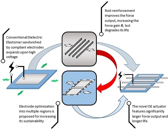
1.3. Motivation and Approach

The aim is to study the force output and the durability of a RP-DEA structure, which incorporates rigid metallic rods to maintain the pre-strain and constrain the expansion in the lateral direction. The force output of a conventional DEA under bi-axial pre-strain is compared with the RP-DEA. It is shown how the RP-DEA outperforms the conventional DEA in force output by gaining the advantages from both pre-strain and motion constraint. The durability of the RP-DEA is evaluated. Through Finite Element simulation it is shown that the non-uniform deformation of the DE is a primary source of premature failure of the RP-DEA. Finally, by optimizing the active region (AR) configuration, the durability of the RP-DEA can be significantly improved without requiring any other modifications to the structure.

2. Theory

The RP-DEA utilizes both pre-strain and motion constraint to improve the force output. This section derives the correlation between the bi-axial pre-strains and the force output of a DEA, to be compared with experimental data.
The force outputs of a DEA are parameters of importance. In an in-plane direction denoted by the subscript i , let f i be the difference between the force in the pre-strain state, F p i , and the force in the activated state, F a i , as denoted by:
f i = F p i ( λ 1 , p r e , λ 2 , p r e ) F a i ( E , λ 1 , p r e , λ 2 , p r e )
where λ 1 , p r e and λ 2 , p r e are the in-plane pre-strains, and E is the electric field across the thickness. When external mechanical stresses σ 1 , σ 2 and the electric field E are applied to the DE, the equations of state are [36]:
σ 1 + ε E 2 = λ 1 , p r e W ( λ 1 , p r e , λ 2 , p r e ) λ 1 , p r e   ,   σ 2 + ε E 2 = λ 2 W ( λ 1 , p r e , λ 2 , p r e ) λ 2 , p r e
where W ( λ 1 , p r e , λ 2 , p r e ) is the elastic free energy density function of the elastomer and ε is the dielectric permittivity of the elastomer. When the DE is under pre-strain only, the resultant mechanical stresses, σ 1 and σ 2 , can be solved by setting E = 0 , which gives:
σ 1 = λ 1 , p r e W ( λ 1 , p r e , λ 2 , p r e ) λ 1 , p r e   ,   σ 2 = λ 2 , p r e W ( λ 1 , p r e , λ 2 , p r e ) λ 2 , p r e
The stress differences between the actuated and pre-strained states are:
Δ σ 1 = Δ σ 2 = ε E 2
By assuming that the pre-strains will not significantly affect the dielectric property of the material, the net stresses are functions of the applied electric field and permittivity of the DE. With the assumption of the incompressibility: λ 1 λ 2 λ 3 = 1 , the resultant net forces are related to σ 1 and σ 2 by:
f 1 = σ 1 L 2 H λ 1 , p r e ,   f 2 = σ 2 L 1 H λ 2 , p r e
where L 1 , L 2 and H are the in-plane dimensions and thickness, respectively, of the DE film in the undeformed state. The applied electric field is related to the applied voltage V by:
E = λ 1 , p r e λ 2 , p r e V H
It now follows that:
f 1 = ε V 2 L 2 H ( λ 1 , p r e λ 2 , p r e 2 )   ,   f 2 = ε V 2 L 1 H ( λ 2 , p r e λ 1 , p r e 2 )

3. Experimental Methodology

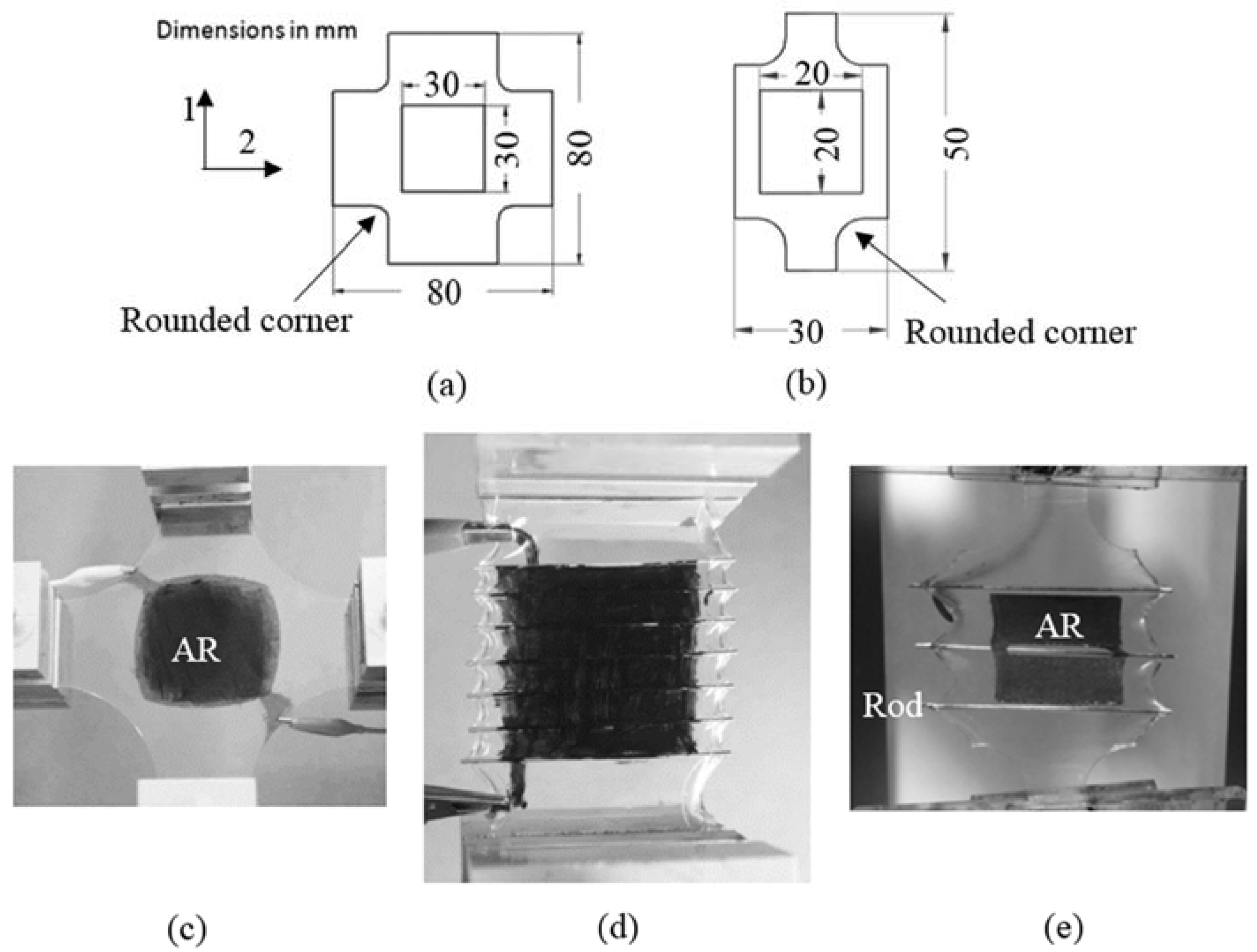
3.1. DEA Configurations

Two experimental assessment phases consisted of: (a) Force Measurement; and (b) Life Assessment. Different DEA configurations were used for each experimental set as shown in Figure 1. In force measurement, the samples were configured to have the total AR area of 30 mm × 30 mm to fit in the bi-axial stretch system shown in Figure 1a,c. The corners near the AR were rounded to avoid stress concentration, hence no mechanical failure for the pre-strain up to 200% in both directions 1 and 2. Subsequently, a RP-DEA with the same configuration was fabricated to compare the force outputs (Figure 1d). In this case, 7 rods were placed with a spacing of 5 mm on the DE film.
For life assessment, the sample size was scaled down with the total AR area of 20 mm × 20 mm as shown in Figure 1b,d. The RP-DEA had only three rods in order to simplify the fabrication process and yield more consistent samples. In addition, 3 AR configurations were used for the durability study. Figure 2a shows the conventional single AR configuration. Figure 2b shows multiple ARs with a gap of 1 mm from the rods. Figure 2a,b has the lead contact point inside the AR. Figure 2c is similar to Figure 2b, but with an additional inactive electrode.

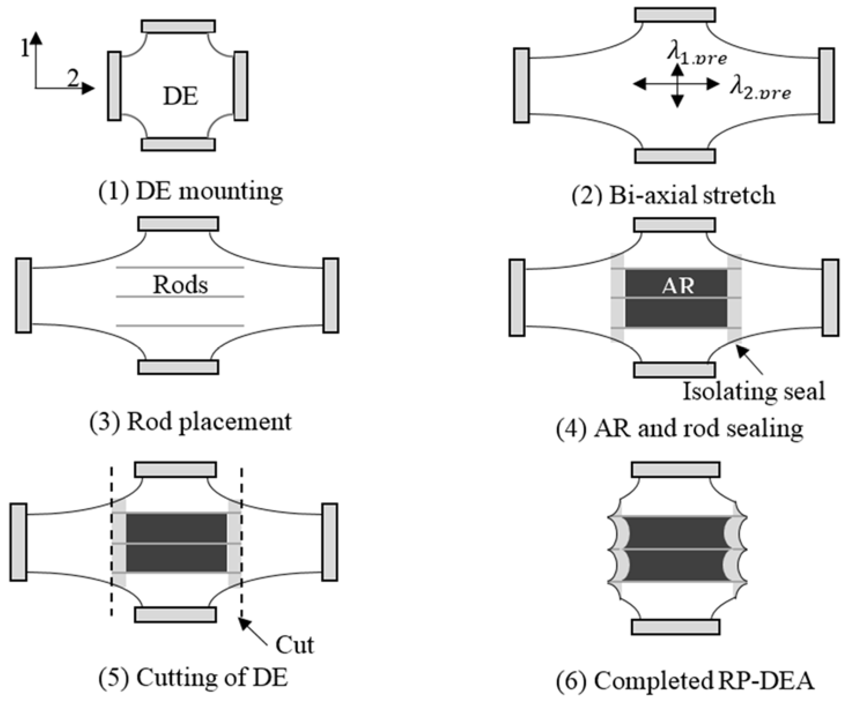
3.2. DEA Fabrication

The dielectric elastomer used in this work was the adhesive acrylic film, VHB 4910, from 3 M (Maplewood, MN, USA). The electrode material was graphite powder. The powder-type electrode was used to ease the screen-printing electrode deposition. The graphite powder was mixed with ethanol prior to the deposition and brush-painted on the DE. The use of ethanol, which vaporized shortly after application, was to improve the coverage of the electrode on the DE. The tested samples were laser cut into the configured shapes. The fabrication sequence of the RP-DEA is presented in Figure 3. The rods used had a diameter of 0.75 mm. They were bonded to the DE film on one side, and sealed by two slices on the other side after the electrode deposition. Such sealing prevented slip between the film and the rods; it also improved the isolation of the electrodes and prevented arcing around the edge. Moreover, because the rods were conductive, it was better to keep their ends sealed in the DE material.

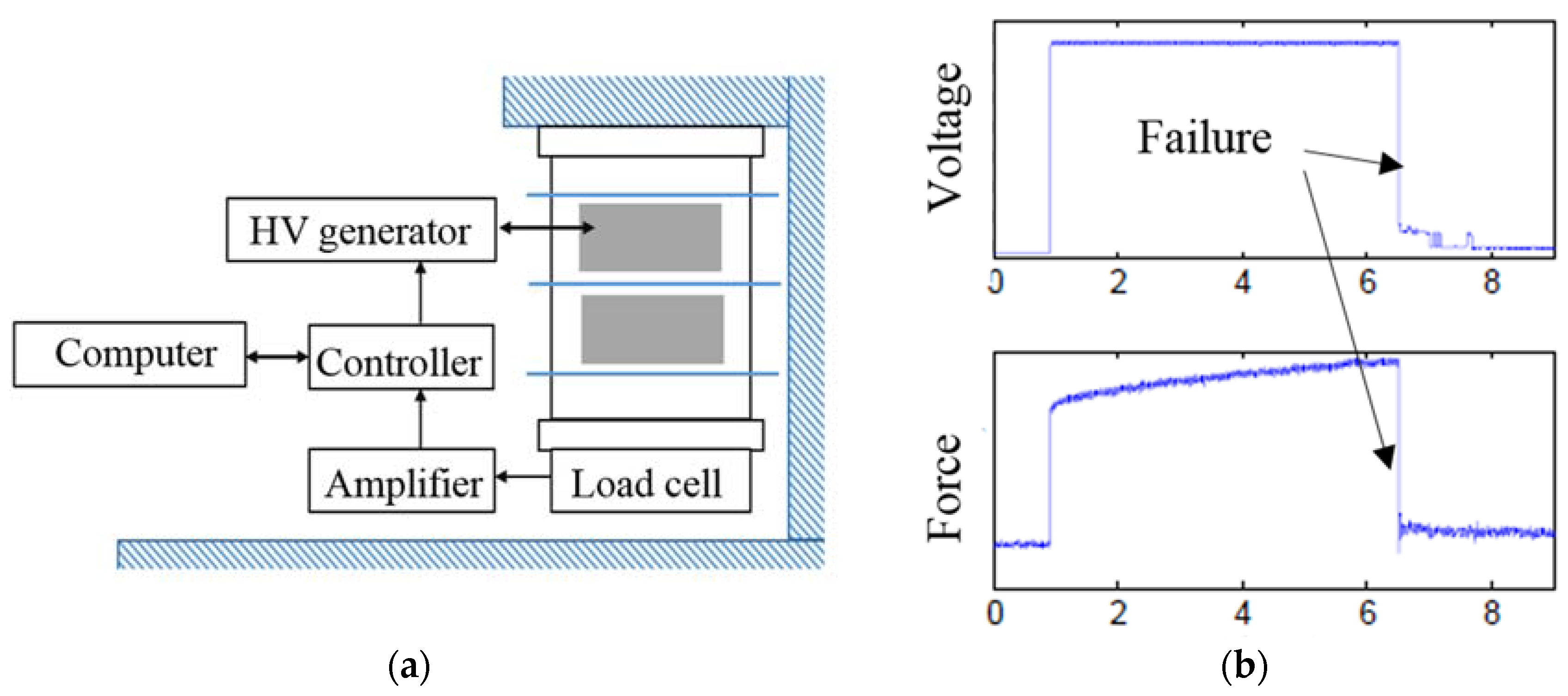
3.3. Experimental Setup and Measurements
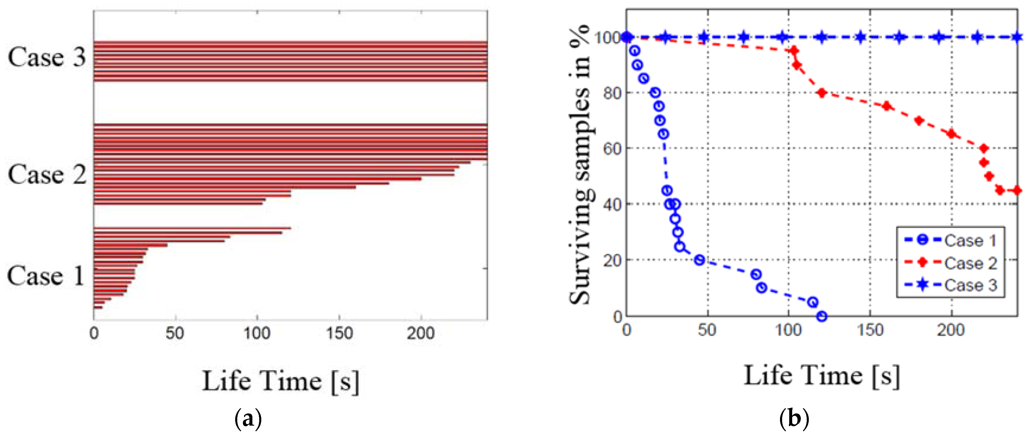
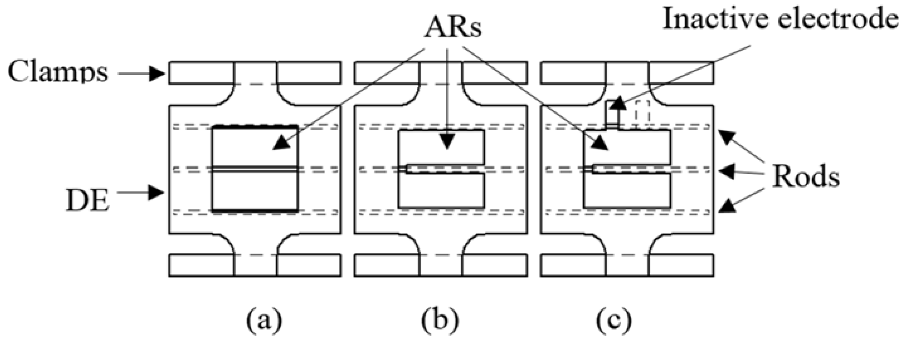
For the force measurements, the conventional DEA samples were configured as in Figure 1a. This layout was used to investigate the effect of bi-axial pre-loading conditions on the actuation force output. The samples were stretched with λ 1 , p r e = 1.2   fixed, and λ 2 , p r e varied from 1.5 to 3 in steps of 0.05. A voltage of 7 kV was applied across each sample and 5 force measurements were taken at each point in both directions via the force sensors in the stretch system. The force output of the RP-DEAs was measured with the same setup, pre-strain and applied voltage, but only in direction 1.
For life assessment, the RP-DEAs under different AR configurations as in Figure 2 were assessed. The assessed lifetime was defined as the time period from the voltage application to the detection of a breakdown failure. The AR configuration was optimized by firstly identifying the failure areas in a conventional RP-DEA and then dividing the AR into multiple regions to avoid weak areas in the structure, as shown in Figure 2a, the experiments were undertaken over three different AR configurations:
Case 1.
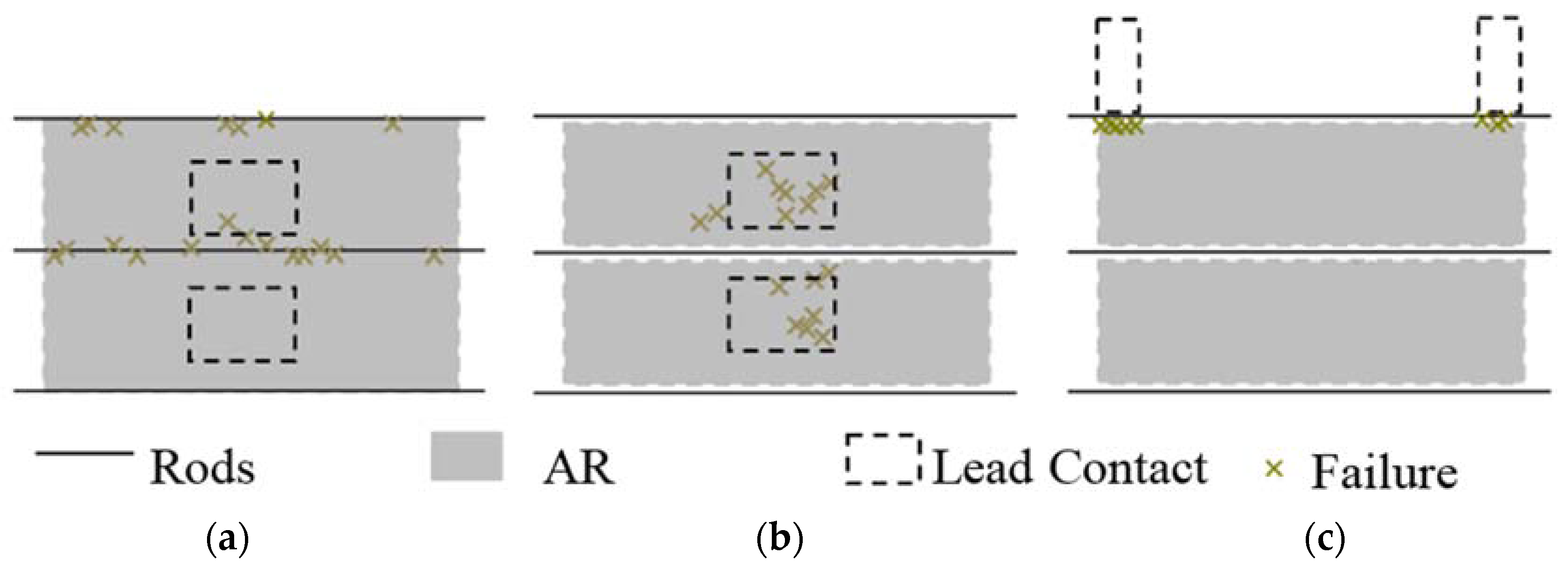
The RP-DEA with a single AR as in Figure 2a, over 20 samples
Case 2.
The RP-DEA with multiple ARs, which exclude the regions associated with rods and have in-AR lead contact as in Figure 2b, over 20 samples
Case 3.
The RP-DEA with multiple ARs and an off-AR lead contact as shown in Figure 2c, over 10 samples
The DE samples were stretched as λ 1 , p r e = 1.2 and λ 2 , p r e = 3 . The input voltage for all testing was set to be 7.5   kV , the critical voltage that the RP-DEA started to fail. For each sample, its lifetime was recorded.
A high voltage (HV) generator was used to amplify the input voltage (0–10 V) from a programmed system. The actual voltage output (0–15 kV) from the generator was monitored and fed back to detect any rapid voltage drop, which would be the result of short-circuiting hence failure of the DEA (Figure 4b). The experimental layout is shown in Figure 4a. The lead contacts to the electrodes were as shown in Figure 5.

4. Results and Discussion

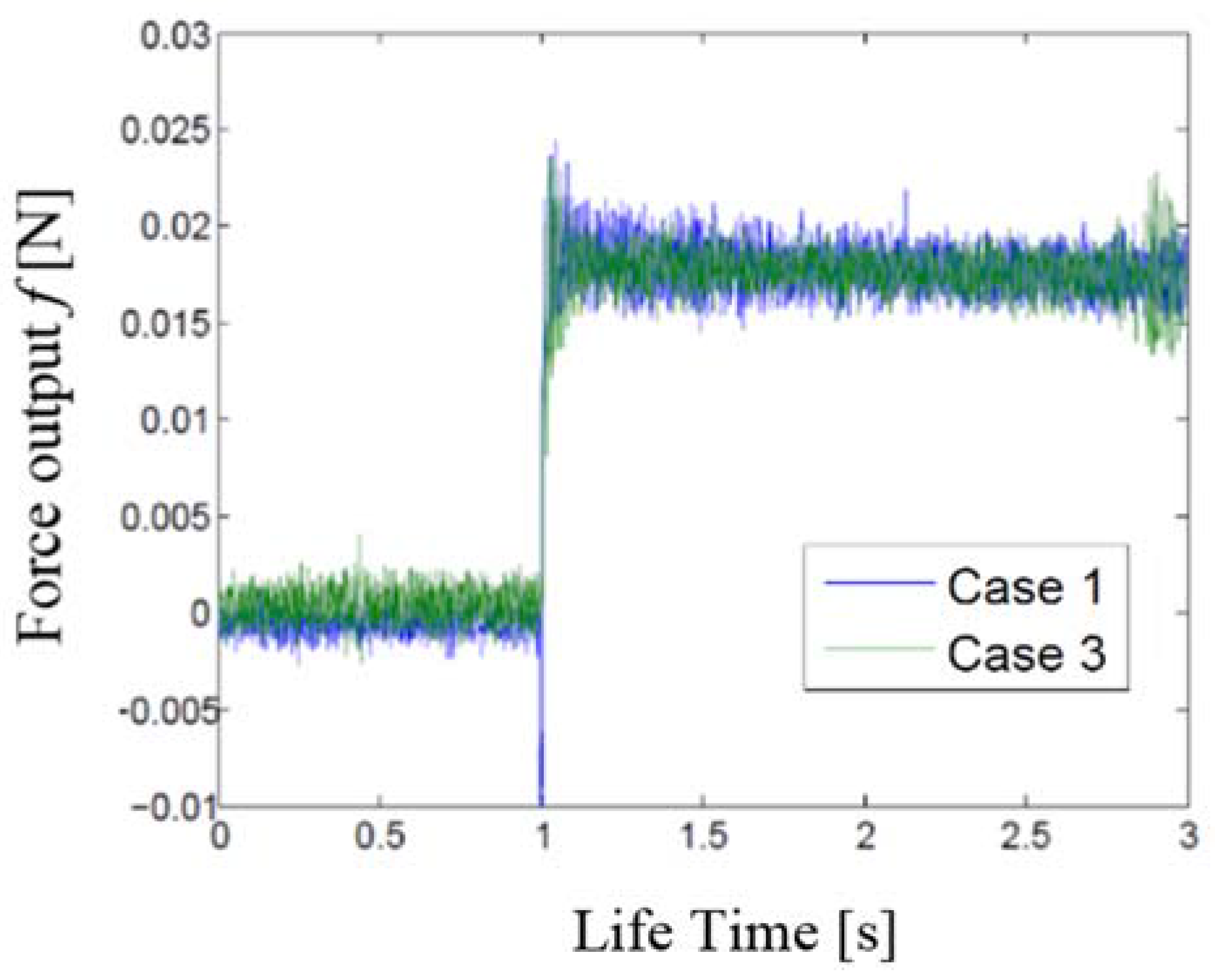
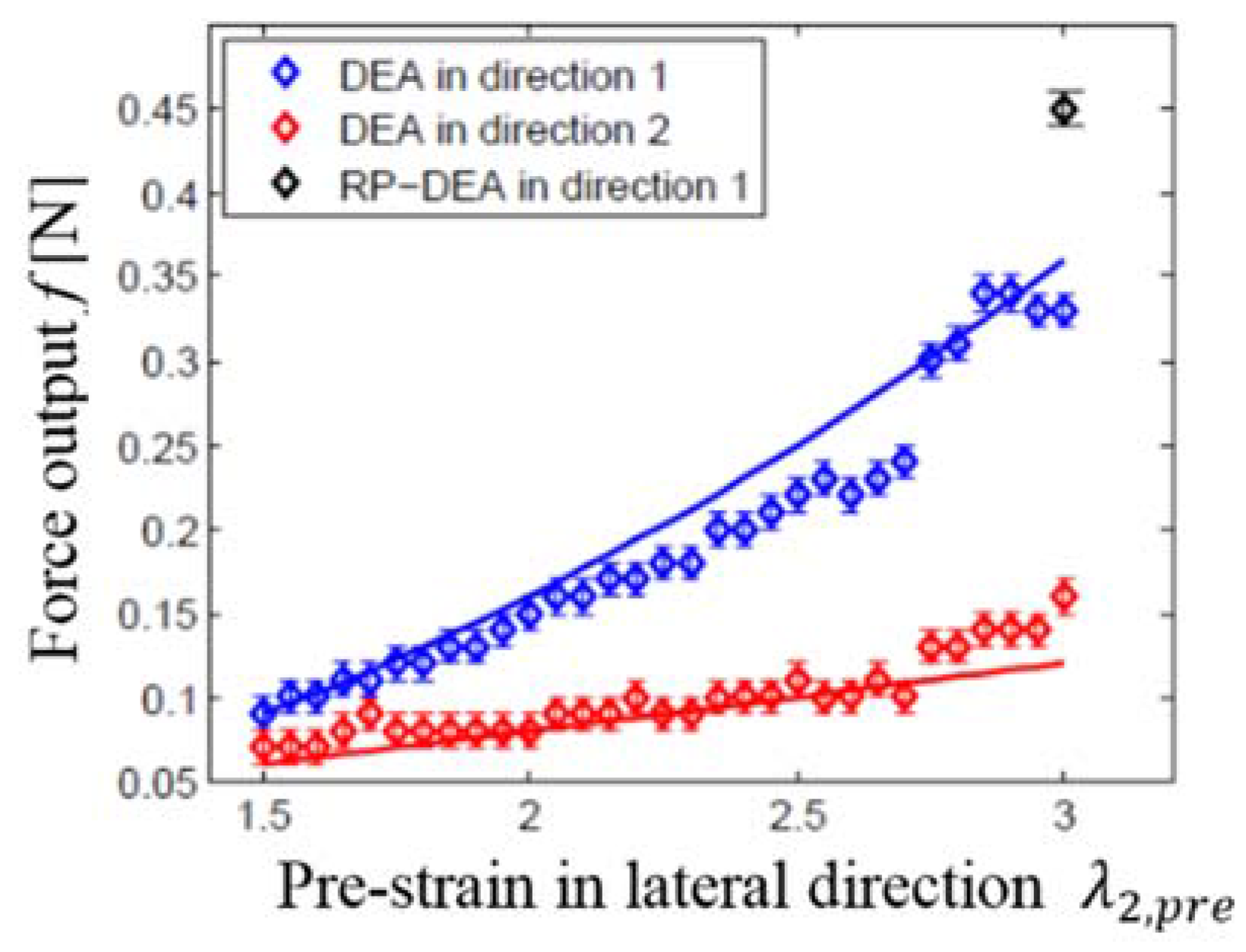
4.1. Force Measurement Results

The force measurement results for the conventional DEA without any rods are shown in Figure 6. The large force outputs and the quicker rising trend were found in direction 1 compared with direction 2. The maximum force outputs were f 2   = 0.17 N (±0.01 N) in direction 2 and f 1   = 0.35 N (±0.01 N) in direction 1 at the maximum pre-strain condition. The results indicate that large pre-strains in direction 2 increased the force outputs in both directions. Pre-strains in direction 2 were observed to be more effective in amplifying the force output in direction 1. An approximate linear relationship is seen between the force outputs and pre-strains in direction 2. The force output from the RP-DEA, which has pre-strain λ 2 , p r e = 3 only, is also shown in Figure 6 for comparison.
It is recalled that Equation (7) was derived from the equation of state for the DE material to describe the effect of bi-axial pre-strain on the actuation force outputs. Figure 6 indicates a good correlation between Equation (7) and the measured actuation forces in both directions. Offsets between the theory and experimental data may be due to the migration of the electrodes on the DEA. Although the electrode material was carefully repainted to both surfaces at each step before the activation, the quality of the re-application could be ensured only on the upper surface of the DEA. It was difficult to access and check the electrode conditions on the lower surface since the mounting condition was maintained for consistency of measurement. Furthermore, in Equation (7), the permittivity of the material is assumed to be constant. Large deformation of the elastomer changes the geometries and arrangements of the polymeric molecule chains, which may potentially vary the electromechanical coupling behavior of the material. In general, the derived correlation shows the potential for it to predict the actuation force output of the DEA structure in a bi-axial loading condition. It can also be used to guide the pre-strain configurations in a DEA design.
With the same pre-strains, λ 1 , p r e = 1.2 and λ 2 , p r e = 3 , the force output of the RP-DEA with the rod configuration was measured to be f 1   = 0.45 N (±0.01 N) in direction 1. It is a higher force output compared with that of the conventional DEA with the same pre-strain, 0.32 N (±0.01 N). The extra force output is due to the motion constraint, as the rods play the role of both maintaining pre-strain and constraining electrode movement in the RP-DEA.
In the durability study of the RP-DEA, the static force responses of the structure as in Figure 1b were also measured to compare between Case 1 and Case 3. Five samples were measured for each case and the results are shown in Figure 7. The force output of the RP-DEA with multi-ARs was found to be 6% less than the force output of the RP-DEA with a single AR. The reason is due to the decrease in the total area of the AR. However, the reduction in force output is considered to be small compared with the 20% reduction in the area of the AR. The narrow gaps between ARs may also slow down the spreading of charge over the AR during the charging phase, hence lead to the change in the dynamics of the RP-DEA. It would require further study to fully identify this effect.

4.2. Lifetime Assessment Results

The lifetime results for all samples are summarized in Figure 8. For Case 1, the operating lifetimes varied significantly from 5 s to 120 s. Overall, 80% of the samples failed within 60 s and the average lifetime was 39 s. The standard deviation was evaluated as 33 s. For Case 2, the average operating lifetime of the structures was increased significantly to 202 s. However, the measured lifetime had broad range of variation, between 103 s and 240 s. The standard deviation was calculated as 51 s. For RP-DEAs in Case 3, all samples survived to the full test duration of 240 s. The applied voltage was then increased gradually until the structures failed. The failing input voltages were found to be consistently around 9.5 kV.
The failures in all three cases were recorded as shown in Figure 9. In Case 1, 95% of failures (19 out of 20) occurred close to the rods (Figure 9a), while 5% of the failures (1 out of 20) occurred around the lead contact point. This indicates the regions close to rods primarily cause the premature failure of the RP-DEA. The electrode deposition should avoid these “weak” regions for the sake of improving the durability. For the RP-DEAs in Case 2), the failures were found to be associated with the center of the AR (Figure 9b), where the tip of the cable contacts the DE in order to connect to the power supply. In this case, because the “weak” regions were no longer activated, the average lifetime increased significantly compared with those in Case 1. The in-AR lead contact was found to be the secondary cause that also causes the premature failure. For the RP-DEAs in Case 3, as both sources of failure were removed from the structure, all samples survived through the full duration of the life-assessment (4 min).

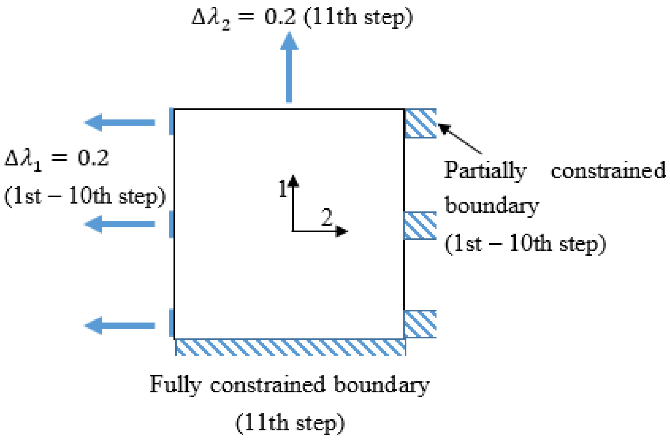
4.3. Finite Element (FE) Simulation Configuration

In order to better understand the primary source of failure, the “weak” regions in the structure, the deformation of the RP-DEA was evaluated by 2D FE simulation. This was implemented using the four-noded rectangular element, Q4, in MATLAB. The elastomer is hyperelastic and if subjected to large deformations ( λ 1 = 3 , λ 2 = 1.2 ) , the FE analysis is nonlinear due to:
C1.
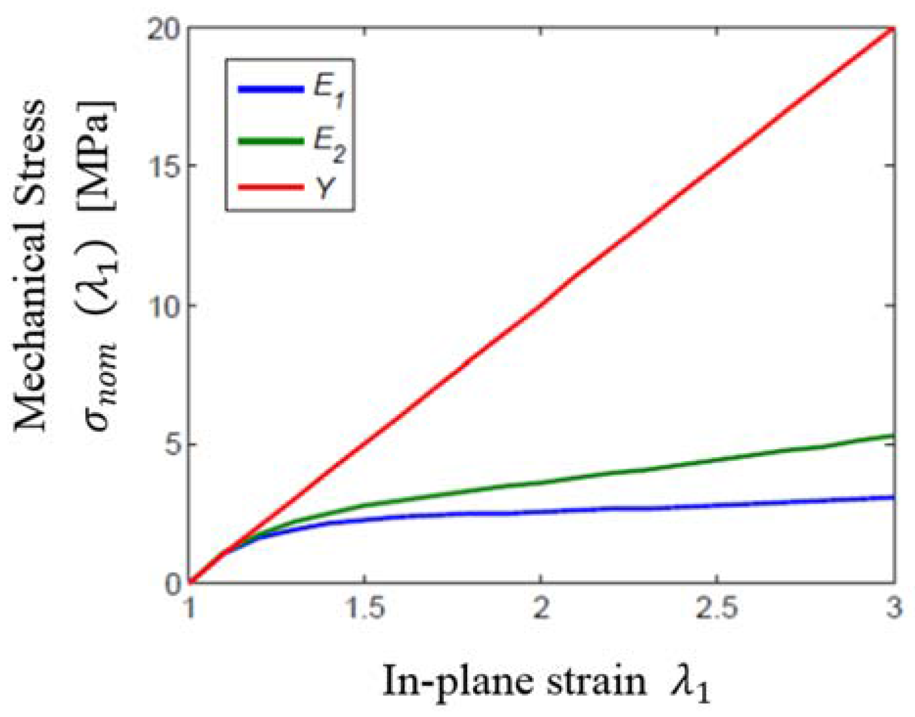
The solid is anisotropic due to bi-axial loading
C2.
The elastic moduli, E i ( λ 1 , λ 2 ) and E 2 ( λ 1 , λ 2 ) , of the DE in the in-plane directions become functions of strains instead of remaining at the constant, Y
The nonlinear analysis was achieved by setting λ 2 = 1 as the initial boundary condition, and splitting the large deformation, λ 1 = 3 , into 10 small deformation steps, Δ λ 1 = 0.2 , from λ 1 = 1 to λ 1 = 3 . The 11th step is applied to strain the DE with λ 2 = 1.2 . Hence, the FE analysis for the j t h   ( j = 1 ,   2 ,   . ,   11 ) step can be considered to be linear with respect to the elastic moduli, E 1     j and E 2     j , as:
{ d j , σ j , ϵ j } = f F E A ( E 1     j   ( λ 1     j , λ 2     j ) ,   E 2     j ( λ 1     j , λ 2     j ) , p j )
λ 1     j = 1 + Δ λ 1 ( j 1 )
λ 2     j = 1
where d j is the vector of nodal displacements after current step, j , σ j , ϵ j are the corresponding vectors of the nodal stress and strain components, and p j is the vector of nodal coordinates that describes the shape of object before the current step. It is defined as:
p i = p 0 + n   =   1 i     1 d n
where p 0 is the vector of nodal coordinates for the object in the undeformed state, and n   =   1 i     1 d n is the summation of all nodal displacements from previously simulated steps. The final stress and strain distributions of the object, σ f i n a l and ϵ f i n a l , are evaluated in the same way as for total deformation in Equation (11):
σ f i n a l = n   =   1 10 σ n   ,   ϵ f i n a l = n   =   1 10 ϵ n
For the large deformation up to λ = 3 , the predictive stress–strain models of elastomer that is proposed by Carpi and Gei [37] was used to describe such nonlinear material behavior:
W = ( 2 3 ) 3 Y ( λ 1 3 2 + λ 2 3 2 + λ 3 3 2 3 )
The model is based on the one-term Ogden energy density function, depending uniquely on the Young’s modulus, Y , which is appropriate for analysis up to the inflection (flex) point of the elastomer in nominal stress–strain correlation. For the VHB 4910 DE acrylic film, λ f l e x = 3.3 . The nominal stresses can be obtained by differentiating Equation (13) to yield the expressions:
σ 1 = 4 9 Y ( λ 1 1 2 λ 1 5 2 λ 2 3 2 ) σ 2 = 4 9 Y ( λ 2 1 2 λ 2 5 2 λ 1 3 2 )
The elastic moduli can be solved by evaluating σ i λ i to give:
E 1 ( λ 1 , λ 2 ) = 2 9 Y λ 1 1 2 + 10 9 Y λ 1 7 2 λ 2 3 2 E 2 ( λ 1 , λ 2 ) = 2 9 Y λ 2 1 2 + 10 9 Y λ 2 7 2 λ 1 3 2
This then gives the complete stress-strain relation. The incompressibility gives the shear modulus as G = Y / 3 , the modified Hooke’s law for this 2D finite element simulation can be expressed in matrix form as:
[ ε 11 ε 22 2 ε 12 ] = [ 1 E 1 ( λ 1 , λ 2 ) v E 2 ( λ 1 , λ 2 ) 0 v E 1 ( λ 1 , λ 2 ) 1 E 2 ( λ 1 , λ 2 ) 0 0 0 3 Y ] [ σ 11   σ 22   σ 12   ]
where v is the Poisson ratio. Figure 10 presents the pre-inflection stress-strain correlation of the elastomer when subjected to large deformation, as appropriate to Equation (15). The elastomer becomes softer as it is stretched further in both directions. The relaxations in both elastic moduli are taken over the discrete steps in the simulation.
Because the simulation is in 2D, it does not generate the compressive strain distribution in the direction of thickness directly. It is reasonable to represent the thickness strain ε 33 as:
ε 33 = 1 ( 1 + ε 11 ) ( 1 + ε 22 )
The applied boundary conditions were configured as shown in Figure 11. The simulated DE was set in a square, which corresponds to the AR as in Figure 2a. The sub-strain Δ λ 1 was applied on the three nodal sets in the left hand side edge of the square from the 1st to 10th steps of the simulation. The three corresponding nodal sets in the right hand side edge were fully constrained. This simulates the applied pre-strain that is held by the rod in direction 2, which was 200% in the experiment. The sub-strain Δ λ 2 was applied to the upper edge of the square, and the lower edge was fully constrained for the 11th step of the simulation. This simulates the 20% pre-strain from the experiment in direction 1.
The quasi-static linear FE simulation used here is to only demonstrate the potential non-uniform thickness distribution of the DE in the RP-DEA. The employed material model does not include the full viscoelasticity of hyperelastic elastomers, and the result only indicates the relative thick and thin regions across the structure. It is insufficient to provide the exact estimation on the deformation.

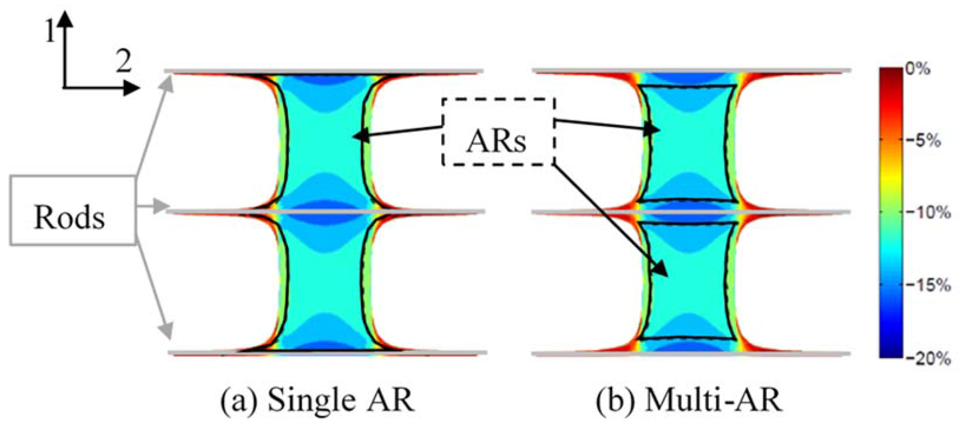
4.4. FE Simulation Results

The simulated results for RP-DEA are presented in Figure 12. It shows the DE to be deformed non-uniformly in the RP-DEA. In general, the thickness of the film decreases as it moves from the edge to the center in direction 2. The three thinnest regions with ε 33 = 17 % are found around the rods, which correlate to the “weak” region that causes the premature failure shown in Figure 8. When the RP-DEA has the single AR as in Figure 12a, the AR covers all these thinnest regions. When the RP-DEA is configured with multi-ARs, the ARs only cover the relatively thin regions with ε 33 > 15 % . It hence avoids the resultant premature failure. In Figure 13, the AR of the RP-DEA, as in Figure 9a, were evenly divided into the left, center and right regions in direction 2. This evaluation suggests that in Case 1, 35% of the failures occurred in the left region; 50% of the failures occurred in the center; 15% of the failures occurred in the right region. It is in agreement with the simulation, where the “weak” regions around the rods cover a larger area in the center region compared with the side regions. More failures would therefore be expected to occur in the center region of the AR.
Considering the three potential sources of failure of the DEA: (i) dielectric strength; (ii) mechanical strength; and (iii) pull-in instability, the most likely failure mode in the RP-DEA is the dielectric strength as explained below:
(i)
Dielectric strength failure: The failure occurs because the resultant local electrical field exceeds the dielectric strength of the film. A 7.5 kV actuation voltage was found to be close to the breakdown voltage of VHB 4910 in agreement with Plante’s work at the same pre-strain condition ( λ 1 , p r e = 1.2 , λ 2 , p r e = 3 ) [27]. Because the DE in the RP-DEA is deformed non-uniformly, the thinnest regions in the film or “weak” regions are close to the dielectric limit. All other relatively thicker regions have the smaller values of local pre-strain and higher breakdown voltages.
(ii)
Mechanical strength failure: For VHB 4910, it has been shown that the film can be stretched up to the pre-strain of 600% [27], which is well beyond the pre-strain configuration in this work. Therefore the mechanical strength is unlikely to be a source of failure.
(iii)
Pull-in instability failure: This failure mode of the RP-DEA is less likely because: (1) no wrinkling was observed prior to the failure; and (2) the RP-DEAs were pre-strained with high stretch rate ( 0.01 s−1). In this case, the viscosity “stiffens” the elastomer and makes it resistant against the pull-in instability [27].

5. Conclusions

An investigation has been undertaken to study the effect of bi-axial pre-loading on the force output of a conventional DEA, compared with that from the new RP-DEA. The derived correlation between the pre-strain and the force output of the DEA was found to fit the experimental data well, covering pre-strain variations up to 200%. The RP-DEA generated larger force by gaining advantages from both pre-strain and motion constraint.
The first RP-DEA design was found to have a short operating lifetime with failure due to its limited dielectric strength. Two sources of failure are identified in this work. The primary failure source is the non-uniform deformation of the DE in the RP-DEA. It creates “weak” regions having low thickness close to the rods, which locally are vulnerable to breakdown voltages. The secondary cause is the in-AR lead contact. The tips that contact the DE have better conductivity than the electrode material, which may concentrate charge and lead to excessive local electrical fields. The in-AR contact is found to have lower impact on the durability of the RP-DEA compared with the primary “weak” region. Both sources of failure were suppressed by optimizing the AR configuration. The results show that this approach stabilizes the RP-DEA to avoid failure due to limited dielectric strength and dramatically improves the durability of the RP-DEA. The results also show that the AR optimization led only to a minor reduction in force output.
Further work is suggested in the life assessment of the RP-DEA with non-conductive rods to assess fully the influence of rod conductivity. The simulation model could be further improved by performing a single continuous simulation, rather than the discrete steps in this paper. A locally defined DE elastic modulus that varies with non-uniform deformation would also be more representative in the model.

Acknowledgments

This work involved international collaboration between the Robotics and Autonomous Laboratory, University of Bath (Bath, UK) and the Smart Material and Device Control Laboratory, Zhejiang University (Hangzhou, China). It was funded by a Global Research Scholarship from the University of Bath.

Author Contributions

Patrick Keogh and Pejman Iravani from Bath are the PhD supervisors of Runan Zhang. They provided the guidance for the analysis and the design of the experiments. Tiefeng Li was the collaborating investigator from Zhejiang who supported the design of the actuators. He is also the supervisor of Xiaoqiang Huang. Runan Zhang and Xiaoqiang Huang performed the experiments, while Runan Zhang analyzed the data. Runan Zhang provided the first draft of the paper while the other authors contributed technical input in their areas of specialty.

Conflicts of Interest

The authors declare that there are no conflicts of interest.

Abbreviations

The following abbreviations are used in this manuscript:
DEDielectric Elastomer
DEADielectric Elastomer Actuator
RP-DEARod Pre-strain Dielectric Elastomer Actuator
ARElectro-Active Region

References

  1. Carpi, F.; De Rossi, D.; Kornbluh, R.; Pelrine, R. Dielectric Elastomers as Electromechanical Transducers; Elsvier: Oxford, UK, 2008. [Google Scholar]
  2. Li, T.; Zou, Z.; Mao, G.; Qu, S. Electromechanical bistable behavior of a novel dielectric elastomer actuator. J. Appl. Mech. Trans. ASME 2014, 81. [Google Scholar] [CrossRef]
  3. Li, T.; Li, C.; Mao, G.; Zou, Z.; Xie, Y.; Qu, S. Novel dielectric elastomer structures with electromechanical instability. Proc. SPIE 2014, 9056. [Google Scholar] [CrossRef]
  4. Li, T.; Li, W.; Zou, Z.; Hong, Z.; Qu, S. Effects of stretching rate and size on the rupture of acrylic dielectric elastomer. Int. J. Appl. Mech. 2014, 6. [Google Scholar] [CrossRef]
  5. Mao, G.; Li, T.; Zou, Z.; Qu, S.; Shi, M. Prestretch effect on snap-through instability of short-length tubular elastomeric balloons under inflation. Int. J. Solids Struct. 2014, 51, 2109–2115. [Google Scholar] [CrossRef]
  6. Zou, Z.; Li, T.; Qu, S.; Yu, H. Active shape control and phase coexistence of dielectric elastomer membrane with patterned electrodes. J. Appl. Mech. Trans. ASME 2014, 81. [Google Scholar] [CrossRef]
  7. Li, T.; Keplinger, C.; Baumgartner, R.; Bauer, S.; Yang, W.; Suo, Z. Giant voltage-induced deformation in dielectric elastomers near the verge of snap-through instability. J. Mech. Phys. Solids 2013, 61, 611–628. [Google Scholar] [CrossRef]
  8. Li, T.; Qu, S.; Yang, W. Electromechanical and dynamic analyses of tunable dielectric elastomer resonator. Int. J. Solids Struct. 2012, 49, 3754–3761. [Google Scholar] [CrossRef]
  9. Li, T.; Qu, S.; Yang, W. Energy harvesting of dielectric elastomer generators concerning inhomogeneous fields and viscoelastic deformation. J. Appl. Phys. 2012, 112. [Google Scholar] [CrossRef]
  10. Li, T.; Qu, S.; Li, Z.; Tao, W.; Wang, M. Investigation of the mechanical properties of the ni-p-CNTs coated copper composite materials: Experiments and modeling. Mater. Sci. Eng. A 2009, 500, 182–187. [Google Scholar] [CrossRef]
  11. Shepherd, R.F.; Ilievski, F.; Choi, W.; Morin, S.A.; Stokes, A.A.; Mazzeo, A.D.; Chen, X.; Wang, M.; Whitesides, G.M. Multigait soft robot. Proc. Natl. Acad. Sci. USA 2011, 108, 20400–20403. [Google Scholar] [CrossRef] [PubMed]
  12. Morin, S.A.; Shepherd, R.F.; Kwok, S.W.; Stokes, A.A.; Nemiroski, A.; Whitesides, G.M. Camouflage and display for soft machines. Science 2012, 337, 828–832. [Google Scholar] [CrossRef] [PubMed]
  13. Stokes, A.; Shepherd, R.F.; Morin, S.A.; Ilievski, F.; Whitesides, G.M. A hybrid combining hard and soft robots. Soft Robot. 2013, 1, 70–74. [Google Scholar] [CrossRef]
  14. Martinez, R.V.; Branch, J.L.; Fish, C.R.; Jin, L.; Shepherd, R.F.; Nunes, R.M.D.; Suo, Z.; Whitesides, G.M. Robotic tentacles with three-dimensional mobility based on flexible elastomers. Adv. Mater. 2013, 25, 205–212. [Google Scholar] [CrossRef] [PubMed]
  15. Lin, H.T.; Leisk, G.G.; Trimmer, B. Goqbot: A caterpillar-inspired soft-bodied rolling robot. Bioinspir. Biomim. 2011, 6. [Google Scholar] [CrossRef] [PubMed]
  16. Ma, K.Y.; Chirarattananon, P.; Fuller, S.B.; Wood, R.J. Controlled flight of a biologically inspired, insect-scale robot. Science 2013, 340, 603–607. [Google Scholar] [CrossRef] [PubMed]
  17. Mannsfeld, S.C.B.; Tee, B.C.K.; Stoltenberg, R.M.; Chen, C.V.H.H.; Barman, S.; Muir, B.V.O.; Sokolov, A.N.; Reese, C.; Bao, Z. Highly sensitive flexible pressure sensors with microstructured rubber dielectric layers. Nat. Mater. 2010, 9, 859–864. [Google Scholar] [CrossRef] [PubMed]
  18. Jung, K.; Kim, K.J.; Choi, H.R. A self-sensing dielectric elastomer actuator. Sens. Actuators A Phys. 2008, 143, 343–351. [Google Scholar] [CrossRef]
  19. Anderson, I.A.; Gisby, T.A.; McKay, T.G.; O’Brien, B.M.; Calius, E.P. Multi-functional dielectric elastomer artificial muscles for soft and smart machines. J. Appl. Phys. 2012, 112. [Google Scholar] [CrossRef]
  20. Anderson, I.A.; Hale, T.; Gisby, T.; Inamura, T.; McKay, T.; O’Brien, B.; Walbran, S.; Calius, E.P. A thin membrane artificial muscle rotary motor. Appl. Phys. A Mater. Sci. Process. 2010, 98, 75–83. [Google Scholar] [CrossRef]
  21. Brochu, P.; Pei, Q. Advances in dielectric elastomers for actuators and artificial muscles. Macromol. Rapid Commun. 2010, 31, 10–36. [Google Scholar] [CrossRef] [PubMed]
  22. Liu, Y.; Liu, L.; Zhang, Z.; Jiao, Y.; Sun, S.; Leng, J. Analysis and manufacture of an energy harvester based on a mooney-rivlin-type dielectric elastomer. EPL 2010, 90. [Google Scholar] [CrossRef]
  23. Liu, L.; Luo, X.; Liu, Y.; Leng, J. Dielectric elastomer energy harvesting undergoing polarization saturation. Proc. SPIE 2012, 8340. [Google Scholar] [CrossRef]
  24. Pelrine, R.E.; Kornbluh, R.D.; Joseph, J.P. Electrostriction of polymer dielectrics with compliant electrodes as a means of actuation. Sens. Actuators A Phys. 1998, 64, 77–85. [Google Scholar] [CrossRef]
  25. Koh, S.J.A.; Li, T.; Zhou, J.; Zhao, X.; Hong, W.; Zhu, J.; Suo, Z. Mechanisms of large actuation strain in dielectric elastomers. J. Polym. Sci. Part B Polym. Phys. 2011, 49, 504–515. [Google Scholar] [CrossRef]
  26. Lucking Bigué, J.; Chouinard, P.; Proulx, S.; Miron, G.; Plante, J.S. Preliminary assessment of manufacturing impacts on dielectric elastomer actuators reliability. In Proceedings of the CANSMART 2009—International Workshop Smart Materials & Structures, Montreal, QC, Canada, 22–23 October 2009.
  27. Plante, J.S.; Dubowsky, S. Large-scale failure modes of dielectric elastomer actuators. Int. J. Solids Struct. 2006, 43, 7727–7751. [Google Scholar] [CrossRef]
  28. Yuan, W.; Lam, T.; Pei, Q. Durable dielectric elastomer actuators via self-clearable compliant electrode materials. In Proceedings of the Materials Research Society Symposium, Boston, MA, USA, 1–4 December 2008; pp. 183–190.
  29. Lu, T.; Huang, J.; Jordi, C.; Kovacs, G.; Huang, R.; Clarke, D.R.; Suo, Z. Dielectric elastomer actuators under equal-biaxial forces, uniaxial forces, and uniaxial constraint of stiff fibers. Soft Matter 2012, 8, 6167–6173. [Google Scholar] [CrossRef]
  30. Huang, J.; Lu, T.; Zhu, J.; Clarke, D.R.; Suo, Z. Large, uni-directional actuation in dielectric elastomers achieved by fiber stiffening. Appl. Phys. Lett. 2012, 100. [Google Scholar] [CrossRef]
  31. Ahmadi, S.; Gooyers, M.; Soleimani, M.; Menon, C. Fabrication and electromechanical examination of a spherical dielectric elastomer actuator. Smart Mater. Struct. 2013, 22. [Google Scholar] [CrossRef]
  32. Heydt, R.; Pelrine, R.; Joseph, J.; Eckerle, J.; Kornbluh, R. Acoustical performance of an electrostrictive polymer film loudspeaker. J. Acoust. Soc. Am. 2000, 107, 833–839. [Google Scholar] [CrossRef] [PubMed]
  33. Cakmak, E.; Fang, X.; Yildiz, O.; Bradford, P.D.; Ghosh, T.K. Carbon nanotube sheet electrodes for anisotropic actuation of dielectric elastomers. Carbon 2015, 89, 113–120. [Google Scholar] [CrossRef]
  34. Subramani, K.B.; Cakmak, E.; Spontak, R.J.; Ghosh, T.K. Enhanced electroactive response of unidirectional elastomeric composites with high-dielectric-constant fibers. Adv. Mater. 2014, 26, 2949–2953. [Google Scholar] [CrossRef] [PubMed]
  35. Bolzmacher, C.; Biggs, J.; Srinivasan, M. Flexible dielectric elastomer actuators for wearable human-machine interfaces. Proc. SPIE 2006, 6168. [Google Scholar] [CrossRef]
  36. Goulbourne, N.; Mockensturm, E.; Frecker, M. A nonlinear model for dielectric elastomer membranes. J. Appl. Mech. Trans. ASME 2005, 72, 899–906. [Google Scholar] [CrossRef]
  37. Carpi, F.; Gei, M. Predictive stress-stretch models of elastomers up to the characteristic flex. Smart Mater. Struct. 2013, 22. [Google Scholar] [CrossRef]
Figure 1. Sample configurations for: experiment sets (a,b); and the actual samples (ce).
Actuators 05 00020 g001
Figure 2. Configured Rod Pre-strained Dielectric Elastomer Actuators (RP-DEAs) in life assessment: (a) single AR; (b) two separate ARs connected via bridge; and (c) two separate ARs with bridge and extended electrode region for connection.
Actuators 05 00020 g002
Figure 3. RP-DEA fabrication sequence.
Actuators 05 00020 g003
Figure 4. Experimental system: (a) test rig set-up; and (b) failure detection through voltage monitoring and force measurement.
Actuators 05 00020 g004
Figure 5. The lead contact method.
Actuators 05 00020 g005
Figure 6. Force measurement results (diamonds) against correlation according to Equation (7) (lines) in direction 1 (blue) and direction 2 (red).
Actuators 05 00020 g006
Figure 7. Comparing static force output in isometric loading with that from a step input voltage: RP-DEA with single AR and RP-DEA with multiple ARs.
Actuators 05 00020 g007
Figure 8. (a) Recorded lifetimes up to 240 s for RP-DEA with single AR (20 samples), with separate ARs (20 samples) and with separate ARs and off-AR contact (10 samples); and (b) accumulated surviving samples as a percentage.
Actuators 05 00020 g008
Figure 9. Recorded failure occurrence in RP-DEAs: (a) with single AR over 20 samples (Case 1); (b) with separate ARs over 16 samples (Case 2); and (c) with separate ARs and optimized connection over 10 samples (Case 3).
Actuators 05 00020 g009
Figure 10. Comparison between the Young’s Modulus of the elastomer ( Y = 0.1   GPa ) and the evaluated elastic modulii E 1 ,   E 2 from Equation (15) (taking λ 2 = 1 ) for both in-plane directions. The actual elastic moduli in both directions decrease as the elastomer undergoes large deformation. The elastomer becomes anisotropic under bi-axial loading.
Actuators 05 00020 g010
Figure 11. Boundary condition configurations for finite element simulations over 11 steps.
Actuators 05 00020 g011
Figure 12. Thickness strain distribution of a deformed RP-DEA from 2D finite element simulation. The thickness is evaluated from in-plane residual strains ε 11 , ε 22 according to Equation (17) ( h = 0.1   mm ).
Actuators 05 00020 g012
Figure 13. Occurrence of failures in Case 1 as: Seven in the left region; 10 in the center region and three in the right region of the AR (Figure 8a).
Actuators 05 00020 g013

