Design of Contactlessly Powered and Piezoelectrically Actuated Tools for Non-Resonant Vibration Assisted Milling


Mechatronics Group, Department of Mechanical Engineering, Technische Universität Ilmenau, Max-Planck-Ring 12, 98693 Ilmenau, Germany
*
Authors to whom correspondence should be addressed.
Actuators 2018, 7(2), 19; https://doi.org/10.3390/act7020019
Submission received: 22 March 2018
/
Revised: 16 April 2018
/
Accepted: 20 April 2018
/
Published: 24 April 2018
(This article belongs to the Special Issue Piezoelectric Actuators 2018)
Abstract
:This contribution presents a novel design approach for vibration assisted machining (VAM). A lot of research has already been done regarding the influence of superimposed vibrations during a milling process, but there is almost no information about how to design a VAM tool where the tool is actually rotating. The proposed system consists of a piezoelectric actuator for vibration excitation, an inductive contactless energy transfer system and an electronic circuit for powering the actuated tool. The main benefit of transferring the required power without mechanical contact is that the maximum spindle speed is no longer restricted by friction of slip rings. A detailed model is shown that enables for preliminary estimation of the system’s response to different excitation signals. Experimental data are provided to validate the model. Finally, some parts are shown that have been manufactured using the contactlessly actuated milling tool.
1. Introduction
Conventional vibration assisted machining (VAM) comprising drilling, milling, turning, cutting and grinding with small stroke superimposed vibrations on either the cutting tool or the workpiece aims to improve the fabrication processes. It has been an active research area for more than 50 years and has led to some products either as complete vibration assisted machine tools or as add-on vibration tools for conventional machine tools. The main benefits are reduced cutting forces and tool wear, or improvements in surface finishing and chip breaking [1,2,3,4]. Depending on the frequency and amplitude of the superimposed vibration, cutting surfaces can be smoothed or textured [1,2,3].
Vibration assisted texturing (VAT) is a more recent variant of VAM aiming to fabricate textured or structured surfaces by superimposing vibrations at the machining finishing process. Compared to alternative texturing approaches, the advantages are the application for large surface area finishing and cost reduction [5,6]. Furthermore, microstructured surfaces could be beneficial from a tribological point of view [6,7].
Usually, in VAM and VAT, piezoelectric actuators are used, either driven in resonant or non-resonant operation mode [1,2,3]. The resonant mode is restricted to a distinct vibration frequency but comes along with smaller excitation voltage for a given displacement amplitude and compact power electronics due to active power operation. In non-resonant mode, i.e., below the actuators’ first eigenfrequency, broad-band actuator excitation is possible at the cost of higher excitation voltages for a given displacement amplitude and larger power electronic components due to apparent power operation. The vibration frequency and necessary stroke determine the type of the piezoelectric actuator.
In VAM, when enhancing the machining process enhancement, e.g., cutting force and tool wear reduction or chip breakage improvement, is the focus, the piezoelectric actuators are driven at a single excitation frequency in resonance operation mode. The used frequencies are mainly in the ultrasonic frequency range. The advantage of high vibration frequencies is a higher possible upfeed velocity and thus decreased machining time at a given rate of vibrations per tool revolution [1] (p. 157).
Research in VAT is based on non-resonant piezoelectric actuation to allow for nearly arbitrary periodic vibration forms of the tool tip. Both one- and two dimensional vibrations of either the tool tip or the workpiece are under investigation. Almost all actuators designed for examining VAT are non-rotating devices [8,9,10,11]. In [10], a 1D-actuator design was suggested and investigated that allows for vibration frequencies from DC up to 40 kHz. This enlarged frequency range comes at the cost of larger actuator volume. An off-the-shelf 1D-actuator for examining texturing under turning processes was chosen in [8]. As an add-on tool for conventional machines, Ref. [11] developed a 2D-actuator for elliptic cutting processes with rotating workpieces. Similarly, Ref. [12] developed and investigated an 2D-actuator for elliptic VAT in milling processes. There, the actuator is embedded in a cooling chamber. Contrary to the others, in [9], it is not the tool that is actuated but the workpiece, which limits their sizes. The application is also a milling process.
Up to now, only Ref. [13] suggests a milling tool with an integrated rotating piezoelectric actuator. This tool allows for arbitrary cutting profiles. Using a specially shaped cutting plate, they showed the possibility to cut nearly any pattern into the surface of an object. The main disadvantage of this system is that the electrical power is transferred to the actuator using slip rings; therefore, the cutting speed is limited by the maximum speed of these rings, which is determined by the contact friction.
Transferring the required power contactlessly could be beneficial since it allows for higher cutting speeds and therefore shorter manufacturing times. In this contribution, a design procedure will be shown for a contactlessly powered 1D-actuator mounted inside the rotating tool for exciting an axial vibration during the milling process. Furthermore, an experimental setup will be shown that was both used to validate the model and to be able to manufacture parts with a textured surface.
2. System Components
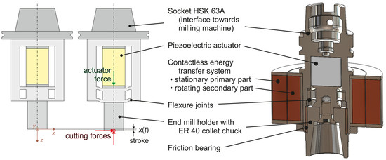
Figure 1 shows the structure of the proposed system. A piezoelectric actuator is used to excite the axial vibration during milling. This actuator is built inside the rotating tool. Hence, the power has to be transferred from the stationary primary part towards the rotating secondary part. This is done contactlessly by a specially designed inductive system in order to be able to use high rotational speeds. The primary part of this subsystem is then powered by a power electronic circuit. These three main components are described in the following paragraphs.
2.1. Actuator
The actuator’s purpose is exciting small axial superimposed vibrations on the milling tool’s horizontal feeding motion with variable frequency for microstructural surface modification or texturing. In the special case considered here, a frequency range between to is demanded. To gain the high forces that come along with this requirement, a piezoelectric transducer was chosen. Using this, it should also be possible to achieve high stroke amplitude compared to the ultrasonic approaches. The demands were to excite forces up to and a stroke of . Since piezoelectric actuators need to be prestressed, the maximum possible force of the actuator needs to be significantly higher. For this reason, an actuator with a blocking force of and a no-load stroke of was chosen (P-035.20P from PI Ceramics GmbH, Lederhose, Germany).
It is well known that piezoelectric transducers are not capable of sustaining shear stress. Since the milling process comes along with lateral cutting forces, a mechanical structure is needed that is soft in axial direction, where vibration is desired, but stiff in lateral direction. A specially designed flexure joint has been introduced for that reason. In addition, it is used for prestressing the actuator. For very high lateral forces, a friction bearing has been inserted to prevent damage of the system.
2.2. Contactless Energy Transfer System
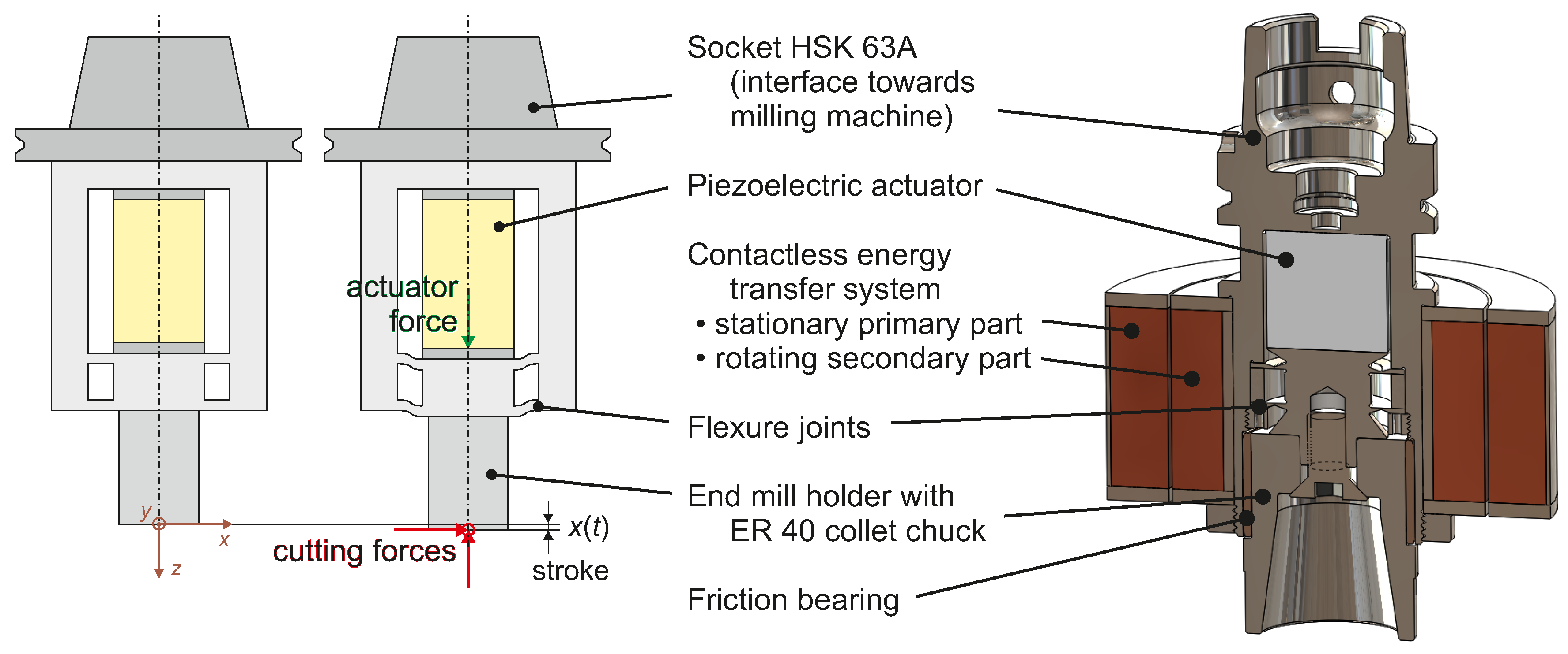
Transferring the power from the power electronics towards the actuator is usually done using slip rings. As mentioned earlier, this concept is not suitable for high speed milling. For this reason, the power is transferred contactlessly using an inductive system. In principle, this system is a transformer where the primary and secondary part are separated by an air gap to allow relative motion between these parts (see Figure 1 and Figure 2).
The approach of using a frequency range and non-harmonic excitation instead of separately transferring power and excitation signal is a consequence of the fact that the secondary part provides no space for additional electronic circuits. It is designed to be as small in diameter and length as possible to ensure low deformation due to cutting forces and low centrifugal forces when rotating at high speeds up to 18,000 rpm. Therefore, the required power has to be transferred already shaped according to the actuator’s desired input signal.
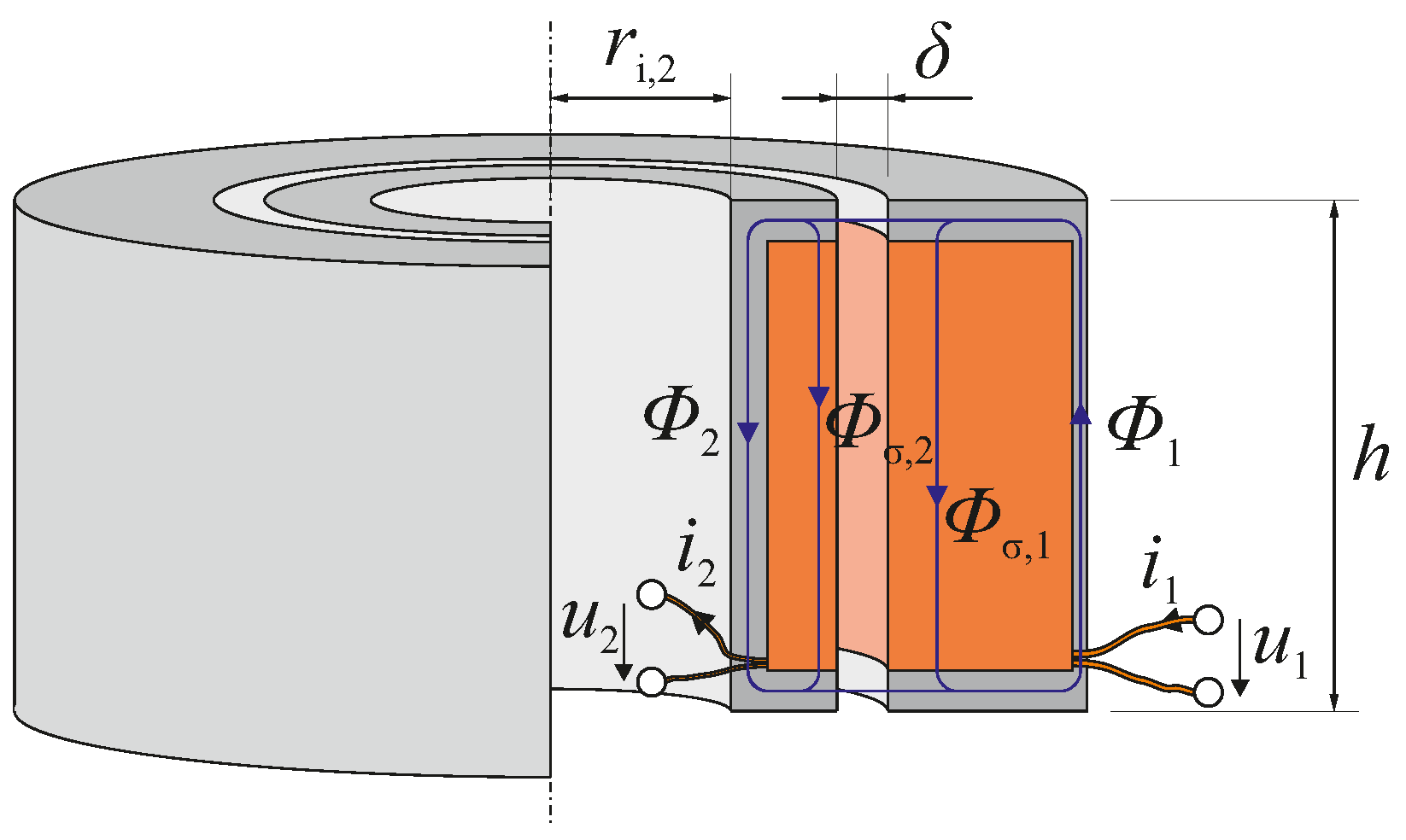
The design concept for the broad-band contactless energy transfer (CET) system also used for this contribution is already presented by the authors in [14]. The proposed concept incorporates the effects of leakage flux and eddy currents. The required input parameters and the calculated output parameters are sketched in Figure 3.
Input parameters comprise geometrical restrictions, limiting parameters, material parameters, but most importantly the apparent power that should be transferred, i.e., , . The required secondary power is a direct consequence of the actuator choice. The primary voltage can be chosen freely and has been chosen as the rectified mains voltage in this special case. The geometrical parameters cannot be chosen as freely. The air gap should be as small as possible while the primary and secondary side still have be easy to assemble onto the milling machine. The inner radius of the secondary side should also be as small as possible to keep centrifugal forces low, but it has to at least be big enough to enclose the piezoelectric actuator and the wall around it. The height of the magnetic circuit h should be chosen to be as large as possible since leakage flux decreases with the height of the circuit. This is restricted by the length of the actuator and its prestress mechanism, i.e., the flexure joints in this case. Finally, one has to chose a nominal frequency. This value should be the maximum frequency of the desired vibration frequency range. This ensures that the secondary current can get at least as high as the demand for the whole frequency range despite the inductive behaviour of the transformer.
Compared to single frequency actuator excitation, variable or broad-band actuator excitation comes at the cost of lower CET efficiency. In single frequency operation, only the active power needs to be transferred as normally the inductive parts are compensated by capacitances. This is the case in ultrasonic VAM where contactless energy transfer is more common. Such a compensation is not possible in broad-band CET operation as considered here. However, according to [15], the positive effect of compensation towards efficiency is small when electromagnetic coupling in the CET is high. The proposed CET has a leakage ratio of about , hence coupling is , so CET efficiency should not be affected significantly (see Appendix A fur further details).
2.3. Power Electronics
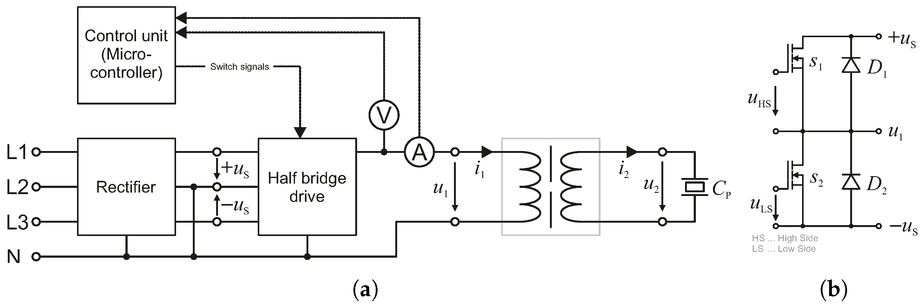
The basic structure of the power electronic circuit is shown in Figure 4. The main component is a bipolar drive in a half bridge topology. Both the supply voltages are provided by a rectifier stage powered by the three-phase mains supply. The rectification is done using six diodes in a B6 configuration.
The half bridge is built up with two n-channel power MOSFET switches with power freewheeling diodes in parallel. The half bridge switches are driven by a dual galvanically isolated half bridge driver controlled by a microcontroller.
3. System Modelling
The system from Chapter 2 can be divided into four subsystems for further analysis. All of these subsystems are described in detail in the following sections.
3.1. Electrical Model of the Primary Part with Power Supply
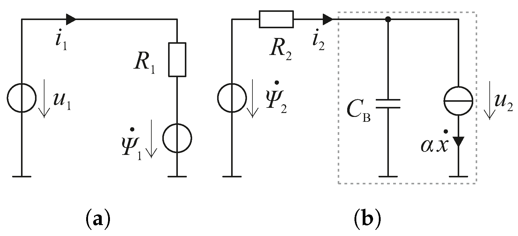
The stationary part consists of the primary part of the transformer, which is part of the contactless power transfer system and the power supply. The transformer’s primary part can be modelled as a voltage source providing the primary induced voltage together with a resistive part . In order to gain a model independent of the actual voltage supply, the excitation is considered as an ideal voltage source . The equivalent circuit for this analysis is shown in Figure 5a. Kirchhoff’s voltage law gives
where is the number of turns in the primary coil and is the magnetic flux flowing through the primary side.
3.2. Electrical Model of the Secondary Part with Piezoelectric Load
The piezoelectric actuator is powered by the secondary induced voltage of the transformer . Piezoelectric actuators can be modelled as a capacitance in parallel with a current source that provides a current proportional to the actuator’s velocity (time derivative of the stroke) . The constant that connects the induced currents with the velocity is the electromechanical transmission factor . In addition, the secondary coil’s resistance is considered. The resulting circuit is shown in Figure 5b. Kirchhoff’s voltage law leads to
where is the number of turns in the secondary coil and is the magnetic flux flowing through the secondary side. Another equation arises from Kirchhoff’s current law,
where denotes the capacitance of the actuator in blocking mode.
3.3. Model of Magnetic Circuit
The magnetic circuit of the CET system that has already been shown in Figure 2 is fundamentally a transformer topology but with two main differences. In a standard transformer, the primary and secondary magnetic flux are the same. In this system, the presence of the gap between the two transformer parts leads to leakage flux , illustrated in Figure 6 and Figure A1, which has been taken into account by means of introducing parallel flux paths via the reluctances and . In addition, different from a transformer designed to operate on mains power, this system is excited with frequencies up to which increases the influence of eddy currents significantly. This effect is modelled by magnetic inductances and . The primary coil’s magnetic excitation is modelled as a magnetic voltage source providing , the secondary coil’s excitation is . For this subsystem, three equations are needed, namely
The leakage flux path corresponding to is newly introduced into the network and was not part of the design process presented in [14]. Secondly, parametrisation of the air gap reluctance has been altered in a way that stray flux around the gap is also considered to influence the value of this parameter and finally the leakage reluctances are now calculated differently to account for the inhomogeneous field distribution (see Appendix A.2 for further details).
3.4. Model of Mechanical Subsystem
The mechanical subsystem can be determined by the law of conservation of momentum. The excitation force is provided by the piezoelectric actuator and is proportional to the voltage across the actuator. Again, the constant connecting these two variables is the electromechanical coupling factor . The mechanical properties that are taken into account are the actuator’s mass as well as the load mass , the stiffness of actuator and load and the damping coefficient of both actuator and load . The actuators inertia effect is introduced with in the equation of motion because it is assumed to be fixed at one end. By varying the load damping, one can analyse the effect of external dissipative load forces as a consequence of the milling process. The equivalent circuit is shown in Figure 7. Momentum conservation then leads to
3.5. State-Space Model and Transfer Functions
Taking Equations (1)–(7), a linear time-invariant state space model can be derived having an order of 5. Solving Equations (1) and (2) for as well as Equation (6) for and subsituting those into the remaining equations results in the state-space model. The state variables are x, , , and . The input variable is . Using Laplace transform transfer functions can be calculated.
4. Model Analysis
4.1. Frequency Domain Analysis
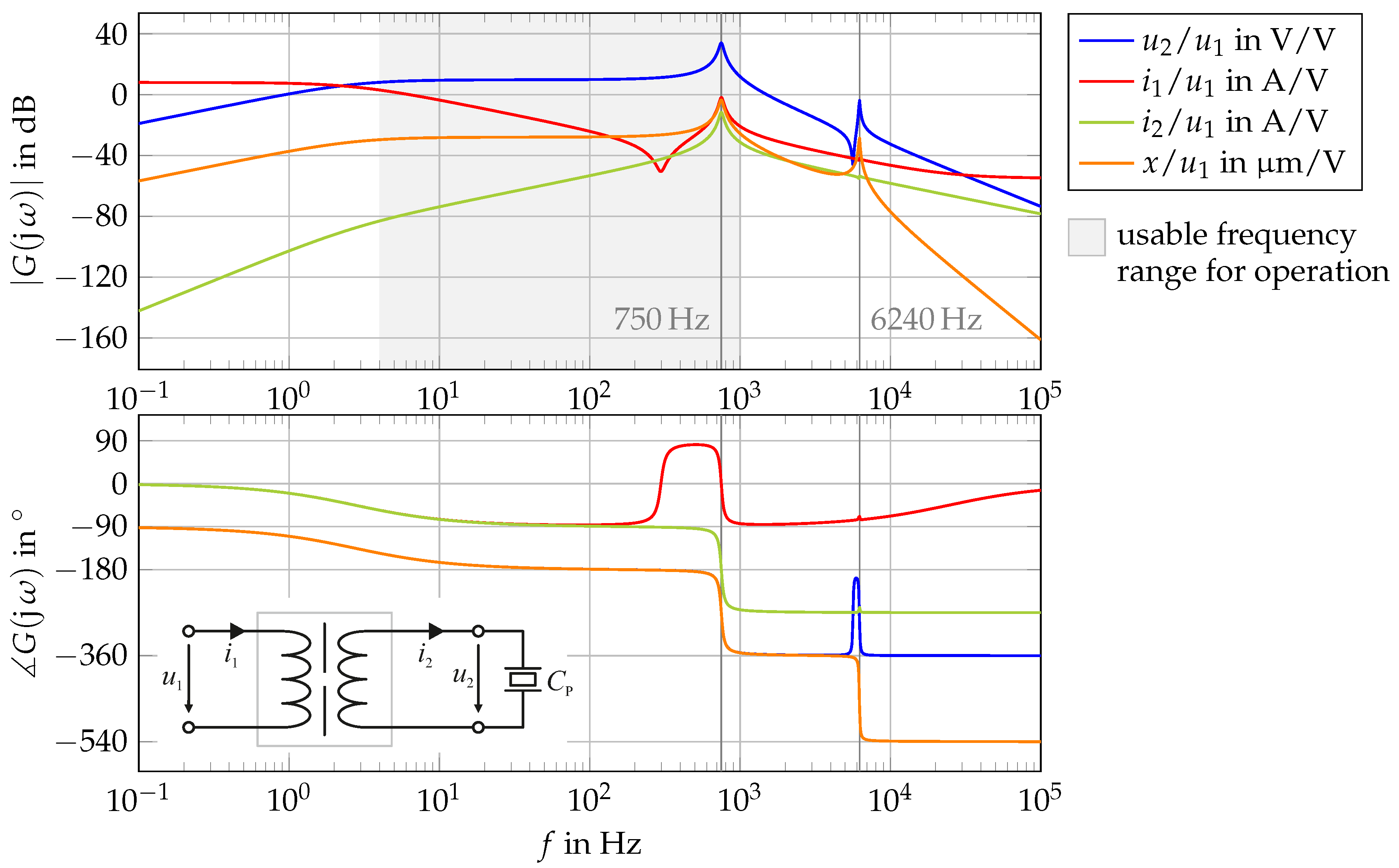
To achieve insights about the system’s behaviour, the frequency response is analysed (see Figure 8). For this analysis, the system is excited by a sinusoidal signal for the input voltage . The parameters for this analysis are provided in Table A2. One can easily see that there are two resonance frequencies. The first one is the electrical eigenfrequency of the secondary part’s inductance and the piezo capacitance. The second one is the mechanical eigenfrequency resulting from mass and stiffness. Both eigenfrequencies are a result of the design process and can therefore not be shifted to a desired value as long as all the input variables shown in Figure 3 are not changed.
Since in this special case one of these frequencies is inside the operating frequency range, the primary side’s voltage amplitude has to be controlled depending on the excitation frequency.
4.2. Surface Forming Analysis
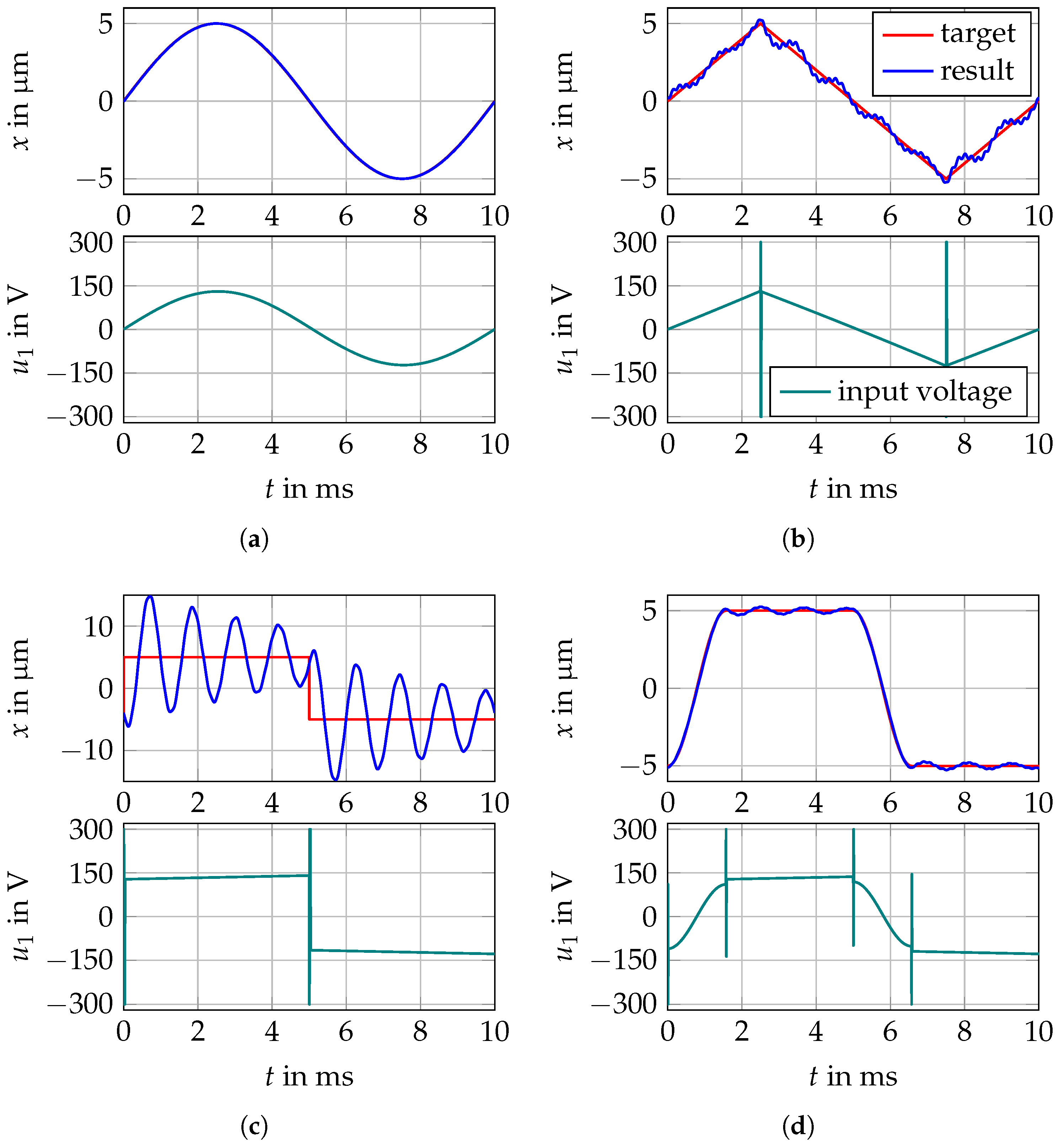
Having calculated the frequency response, these results can be used to derive how the excitation voltage should be shaped to generate a predefined surface structure during the actual milling process. This approach can be obtained using the inverse feed forward method. Therefore, the inverse transfer function of is used to calculate the desired input voltage signal according to the target stroke signal. Since this transfer function has more poles than zeros, additional poles have to be introduced after inversion, having sufficiently low time constants to ensure no significant change in the frequency response within the frequency range of the system’s dynamics.
Analysing the results shown in Figure 9, some limitations of this approach can be deduced. Steps or other discontinuities result in infinite impulses in the excitation voltage signal. Since, in this simulation, the voltage has been limited to the finite supply voltage, there is a huge deviation between target and resulting signal, as can be seen in Figure 9c. Furthermore, signals that are not continuously differentiable also lead to impulses that are impossible to realise, but there is a lesser effect on the stroke signal, which is clearly shown in Figure 9b.
The target stroke therefore has to be continuously differentiable. For a pure sine wave, there is no notable difference between the two signals (see Figure 9a). Discontinuous signals can be smoothed to reduce the vibration excitation due to finite voltage like it has been done in Figure 9d.
Since this calculation results in continuous voltage signals for , an analogue electronic drive would be needed to exactly follow the required signal. Assuming a sufficiently high switching frequency, this continuous signal can be transformed into a pulse width modulated (PWM) signal for half bridge supplies, but this is not within the scope of this contribution.
4.3. Surface Forming Realisation Using Switched Mode Power Electronics
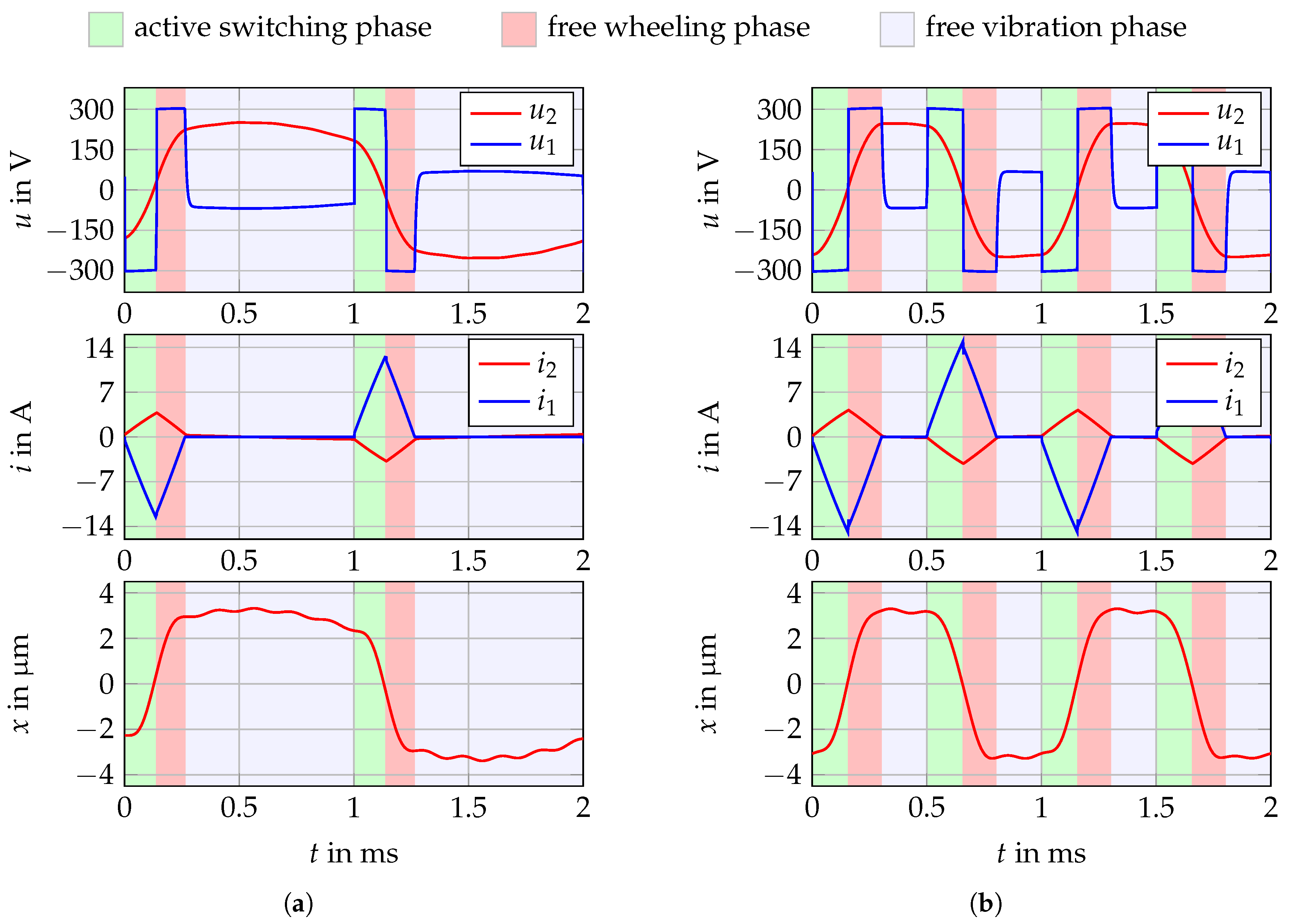
As mentioned in the previous section, surface forming can be done by switching mode electric drives using PWM. Alternatively, the drive could be switched at low frequencies i.e., the target frequency of the stroke itself. This low frequency switching leads to a discontinuous mode meaning that there are time intervals in each period where the current through the switches is zero. This approach lacks the flexibility of PWM but is beneficial since during these phases the secondary current induces a voltage on the primary side, which can be used to determine the secondary voltage. This information is important to assure that the voltage across the actuator does not exceed the maximum allowed values at any time. The turn-on time of the transistors is controlled according to the measured voltage level. This control strategy divides each half of one period into three different phases as illustrated in Figure 10.
- (1).
- active switching phase: Either switch or switch are closed. During this phase, the half bridge output voltage is roughly one of the supply voltages, . The according transistor is turned on, and the absolute value of the primary current is rising. The length of this time interval is determined by the control unit.
- (2).
- free wheeling phase: Both switches are open. Free wheeling is a consequence of the fact that the primary current is unable to step towards zero due to the inductive behaviour of the primary coil. Since during this phase both switches are open, current passes through the opposing diode. Hence, the half bridge output is connected to the opposite supply voltage and the primary current’s absolute value is decreasing. The duration of this phase cannot be controlled. It lasts until the primary current becomes zero.
- (3).
- free vibration phase: Both switches are open. During this last phase, the primary current is zero. Since voltage and current in the secondary part of the transformer are not necessarily zero, there is an induced voltage at the half bridge’s output, , which can be measured for controlling the turn-on time. In theory, it is possible that the induced voltage could exceed one of the supply voltages. In this case, again, free wheeling would occur. Without significant load forces acting on the piezoelectric actuator, this can never happen. This sequence repeats itself, alternatingly switching and .
The control scheme for the transistor’s turn-on time has been chosen to be very simple. During the free vibration phase, the secondary voltage is almost at its maximum and nearly constant right after the switches have been closed. In addition, the re-induced primary voltage is proportional to the secondary voltage in this phase. For these reasons, the turn-on time should be increased (e.g., incremented by a constant value) when the secondary voltage is lower than the desired value and vice versa. Controlling the turn-on time is not only necessary because there is a resonance frequency within the operating frequency range. It is also mandatory to ensure that the secondary voltage is independent of the load forces. Since milling dissipates energy, the secondary voltage would decease without the control circuit.
The model proposed in Section 3 is capable of describing the system’s behaviour in phases 1 and 2. In phase 3, the input variable changes towards the primary current since there is an induced voltage due to secondary current flow, but no current is flowing through the primary side of the transformer. During this phase, the order of the system decreases to 4. One can easily deduce the model for this phase by setting to zero in Equations (1)–(7). Using these two mathematical models and the switching conditions between the three phases, a time simulation can be carried out. The results of the simulation in the time domain are shown in Figure 10 for two exemplary frequencies.
5. Model Based Design Procedure
The design procedure, as proposed here, starts with the actuator design, followed by the CET and finishes with the power electronics design:
- (1).
- Machining Process: The considered surface structuring processes determines the main parameters for a periodic tool vibration in axial direction : the maximum vibration frequency, , transferable by the actuator, the maximum vibration displacement amplitude, , and the maximum cutting force in axial direction, , of the periodic motion.
- (2).
- Actuator: Based on the machining process parameters, no-load stroke and blocking force of the piezoelectric actuator are chosen, resulting in the design parameters , the nominal excitation frequency , secondary voltage and secondary current , respectively. The primary electric voltage is chosen according to available power systems, e.g., three-phase power system in our case. All three parameters are input parameters of the CET in Figure 3.
- (3).
- CET system: Next, the magnetic and electric materials with parameters as well as coil and magnetic circuit design parameters can be chosen. What remains are the input geometric parameters which can be chosen as described on Section 2.2.
- (4).
- After determining the CET, a system analysis must be carried out to check if the calculated electro-magneto-mechanical system comprised of piezoelectric actuator and CET delivers a first eigenfrequency at the border or beyond the nominal frequency . If this is not the case, then the CET system has to be redesigned using other input parameters.
6. Experimental Results
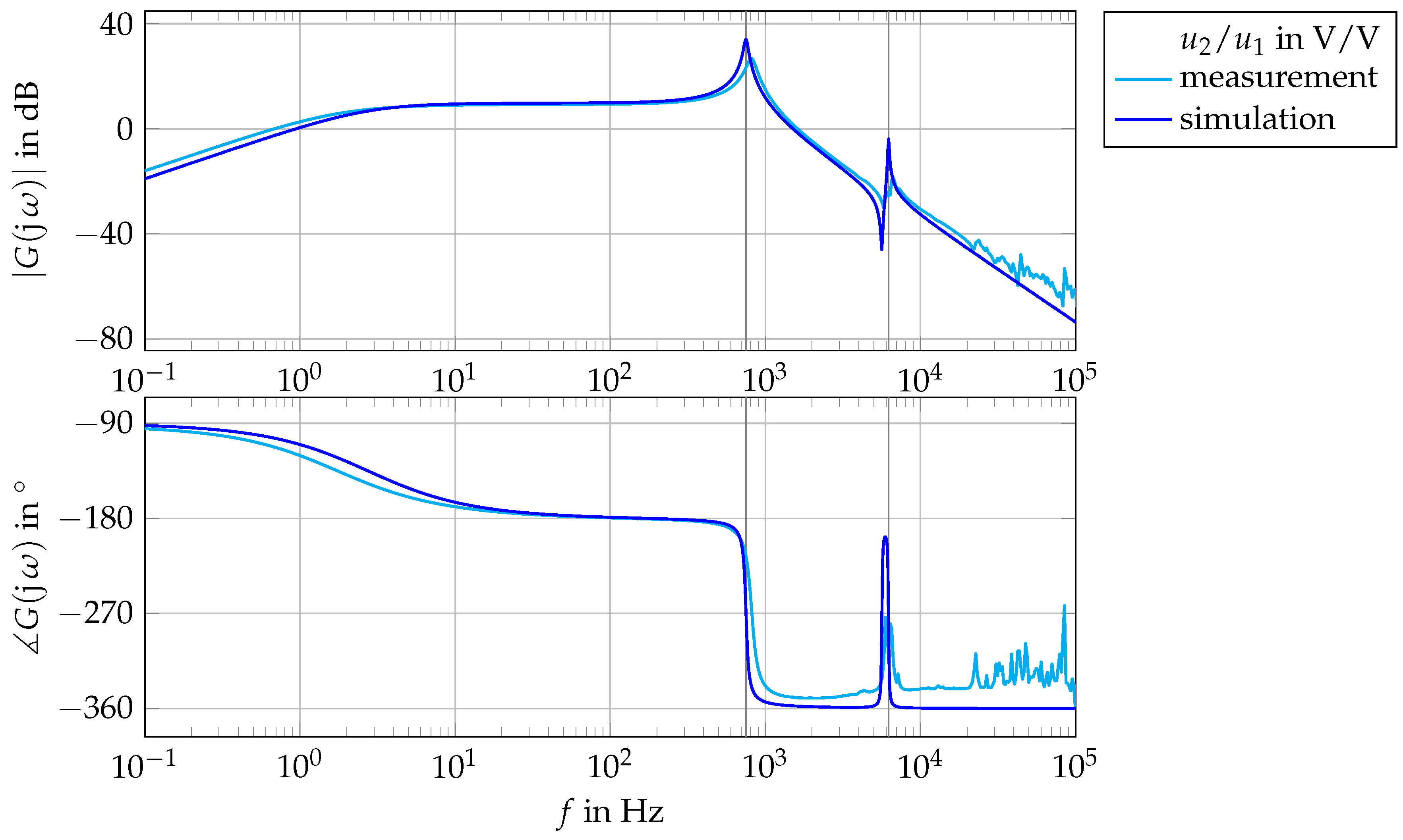
To show that the proposed mathematical model is capable of describing the system’s behaviour, an experimental setup has been built consisting of a piezoelectric actuator powered by a transformer with an air gap. The setup is shown in Figure A2. In the first step, the frequency response has been measured in a small signal range using a frequency response analyser (N4L PSM1735) and an analogue drive for as a buffer instead of the half bridge drive. The measured data for the transfer function is shown in Figure 11 together with the previously shown simulated one.
It can be clearly seen that the two functions fit well qualitatively, but there are deviations in distinct characteristics like resonant frequencies, damping factors and the cut-off frequency. Since there are tolerances when building up test setups and the simulated data has not been fitted to the measurements, this deviation is acceptable.
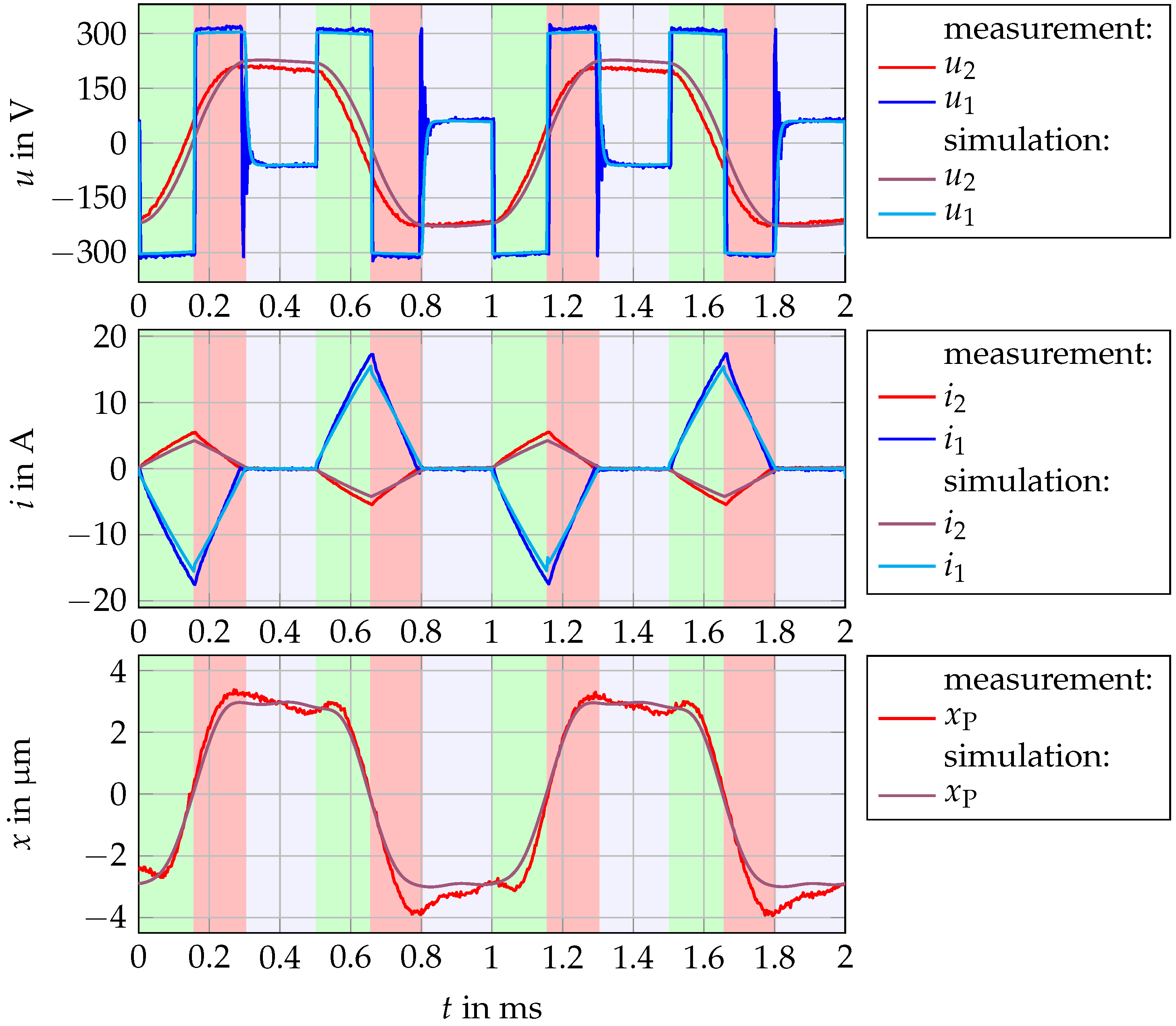
Large signal measurements have been carried out using the aforementioned half bridge drive operating in discontinuous mode as described in Section 4.3. The measured data has been recorded by two digital oscilloscopes. The voltages have been measured using 100:1 probes, and currents have been measured by 10:1 current probes. The stroke has been calculated by integrating the velocity signal of a laser doppler vibrometer. As can be seen in Figure 12, the simulated signals match the measured ones well. The most significant deviation between expected and real values occurs in the signal of secondary voltage because of a delay between the two values.
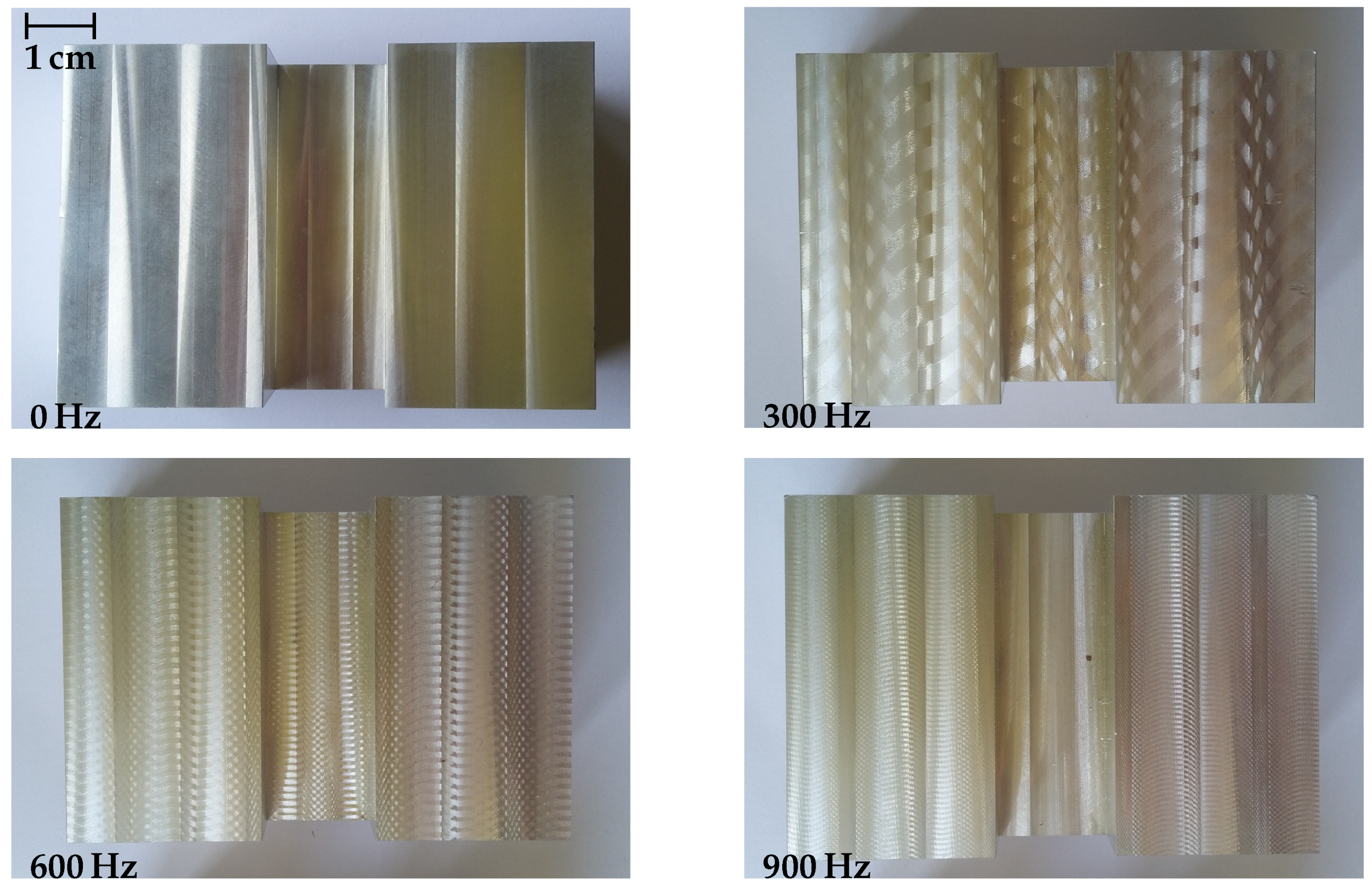
Furthermore, some example parts have been manufactured using the VAM tool, which are shown in Figure 13. Different excitation frequencies have been used while keeping the machining parameters given in Table A1 and the vibration stroke constant. One can see that the surface has been structured during the milling process. Further investigations regarding the properties of these surfaces have to be done. In addition, an investigation regarding the choice of the vibration’s frequency f depending on the spindle speed needs to be done. For this, the ratio of these two parameters can be defined. The parts shown in Figure 13 have been cut using a in the range of six to 18 vibration cycles per tool revolution.
7. Conclusions
In this contribution, it has been shown how a contactlessly powered and piezoelectrically actuated VAM tool can be designed. An experimental setup has been developed that provides the possibility to verify the system’s behaviour predicted by the presented mathematical model. The correlation between measured and modelled values is convincing, both in time and frequency domain. However, it has been shown that the there are slight deviations between the absolute values.
Moreover, the experimental setup has been used to manufacture sample parts having a structured surface. Further research has to be done regarding the properties of the machined surfaces.
Author Contributions
Martin Silge designed the system and the experiments. He also carried out all the experiments. Thomas Sattel supervised the project and analysed and discussed the results together with Martin Silge. Both authors wrote the paper.
Funding
This research was funded by the German Federal Ministry for Economic Affairs and Energy (Bundesministerium für Wirtschaft und Energie), grant number KF2184762AT4.
Acknowledgments
The authors gratefully acknowledge financial support of this work by the German Federal Ministry for Economic Affairs and Energy (BMWi) and evaluation as well as acceptance of this industrial research and development proposal by the German Federation of Industrial Research Associations (AiF). Also, we acknowledge support for the Article Processing Charge by the German Research Foundation (DFG) and the Open Access Publication Fund of the Technische Universität Ilmenau.
Conflicts of Interest
The authors declare no conflict of interest. The founding sponsors had no role in the design of the study; in the collection, analyses, or interpretation of data; in the writing of the manuscript, and in the decision to publish the results.
Abbreviations
The following abbreviations are used in this manuscript:
| VAM | Vibration assisted machining |
| VAT | Vibration assisted texturing |
| CET | Contactless energy transfer |
| PWM | Pulse width modulation |
| CNC | Computerised Numerical Control |
| HSS PM | Powder-metallurgically made high speed cutting steel |
Appendix A. Parameterisation of the Mathematical Model
Appendix A.1. Parameters of Piezoelectric Actuator
The capacitance in blocked mode can be determined using the free capacitance , the electromechanical transmission and the actuator’s stiffness
The values for and can be determined using blocking force, idle stroke and maximum voltage of the actuator, which are all given in the data sheet. The damping of the actuator is not as easy to deduce. A typical value has been determined by assuming a damping ratio of 0.01 and calculating the resulting damping coefficient. The same has been done to estimate the minimum load damping.
Appendix A.2. Parameters of the Magnetic Circuit
The reluctances of the magnetic circuit can be estimated using the flux path length and its cross sectional area,
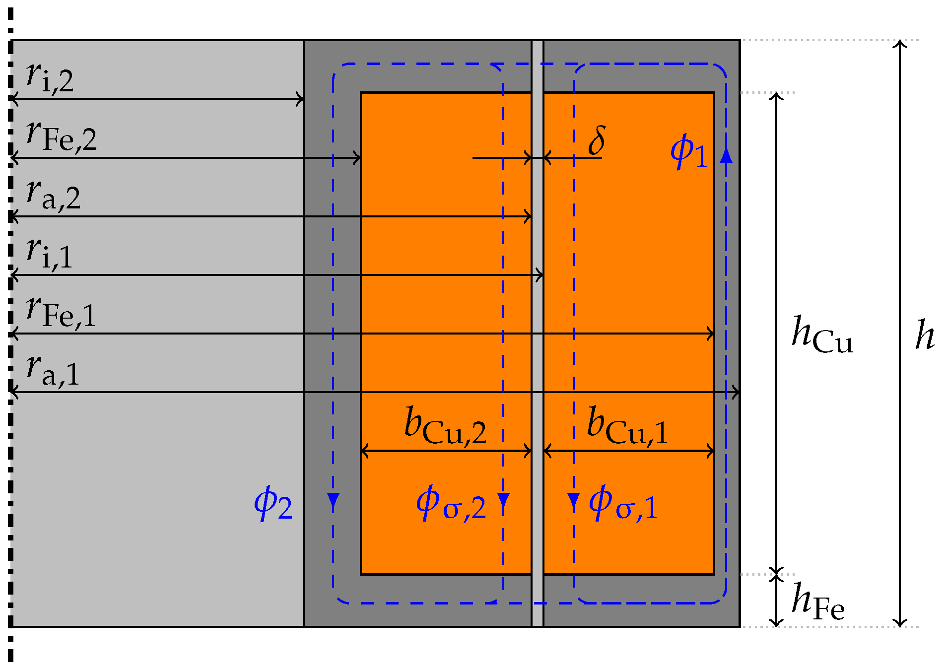
The geometrical parameters are defined as shown in Figure A1. The reluctance of the air gap consists of two components, the reluctance of the actual gap and the reluctance of the stray field ,
These components are connected in parallel, so the air gap reluctance can be determined by , where term describes the stray field around a cylindrical air gap according to [16] (p. 409). The leakage flux reluctances can again be estimated by the leakage flux path length and the area,
but in this case magnetic flux is not equally distributed over the area because of the coil that is inside this region. A correcting factor of 0.5 was used as an approximation neglecting the curvature of the cores.
Estimating the magnetic inductances is the most difficult part. In general, the values are the inverse of the ohmic resistance of the cores, hence
In our special case (laminated and slitted cores), the resistance was assumed to be equal for both primary and secondary cores and was estimated as
which showed to be overestimated by a factor of roughly 4. Since this value is of great importance for the simulation results, some further investigations are needed regarding a better estimation for the value of .
Figure A1.
Sketch of the geometrical parameters of the contactless energy transfer system.

Appendix A.3. Numerical Values
In this work, the numerical values given in Table A2 have been used.

Table A1.
Machining parameters for the first milling trials.
| Workpiece | |
| material | aluminium alloy EN AW-6082 |
| Cutting parameters | |
| spindle speed | |
| feed | |
| feed per tooth | |
| cutting depth | |
| Cutting tool | |
| material | HSS PM |
| diameter | ∅12 mm |
| number of cutting edges | 4 |
| Vibration | |
| stroke | |
| frequencies | 0, 300, 600, 900 Hz |
Table A2.
Numerical values for the test setup and simulation.
| Parameter | Symbol | Value | Unit | Data Source |
|---|---|---|---|---|
| Supply | ||||
| supply voltage | 300 | 1 | ||
| piezoelectric actuator | ||||
| blocking force | 23 | 4 | ||
| idle/no-load stroke | 30 | 4 | ||
| electromechanical transmission | 15 | 4 | ||
| no-load capacitance | 4 | |||
| mass | 4 | |||
| stiffness | 767 | 4 | ||
| damping coefficient | 160 | 5 | ||
| Mechanical load | ||||
| mass | 6 | |||
| stiffness | 383 | 6 | ||
| damping coefficient | 360 | 5 | ||
| Coils | ||||
| primary windings | 190 | - | 7 | |
| secondary windings | 660 | - | 7 | |
| primary resistance | 7 | |||
| secondary resistance | 7 | |||
| Magnetic circuit | ||||
| air gap | 2 | |||
| inner radius (secondary part) | 2 | |||
| outer radius (secondary part) | 7 | |||
| coil width (secondary part) | 7 | |||
| inner radius (primary part) | 7 | |||
| outer radius (primary part) | 7 | |||
| coil width (primary part) | 7 | |||
| coil height | 7 | |||
| total height | h | 2 | ||
| relative permeability | 500 | - | 3 | |
| thickness of laminated sheets | 350 | 2 | ||
| specific resistance | 170 | 3 | ||
Data Sources: 1: Freely selectable; 2: scriptsize Input parameters for design of the contactless energy transfer system (choice according to Section 2.2); 3: Material parameter; 4: Values from datasheet (* only implicitly given); 5: Selectable with further assumptions, see Appendix A.1; 6: Given from mechanical design; 7: Output parameters of CET design.
Appendix B. Experimental Setup
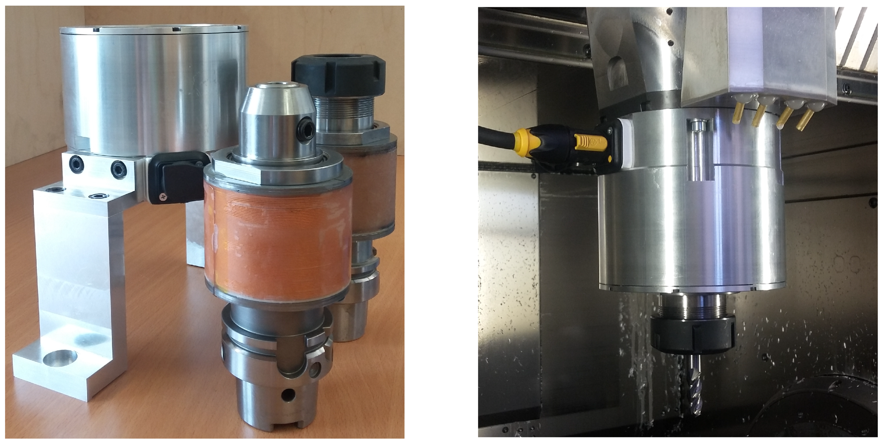
The photographs in Figure A2 show the experimental setup used to generate all the provided data. The stationary primary part is mounted at the non-rotating part of the milling machine, whereas the actuated tool is mounted instead of the conventional end mill holder.
Figure A2.
Photos of the experimental setup, showing primary and secondary parts separately and mounted together on a CNC milling machine.
Figure A2.
Photos of the experimental setup, showing primary and secondary parts separately and mounted together on a CNC milling machine.

References
- Brehl, D.E.; Dow, T.A. Review of vibration-assisted machining. Precis. Eng. 2008, 32, 153–172. [Google Scholar] [CrossRef]
- Maroju, N.K.; Subbu, S.K.; Vamsi, K.P.; Venugopal, A. Vibration Assisted Conventional and Advanced Machining: A Review. Procedia Eng. 2014, 97, 1577–1586. [Google Scholar]
- Kataria, R.; Kumar, J. Ultrasonic machining: A review. Adv. Mater. Res. 2016, 1137, 61–78. [Google Scholar] [CrossRef]
- Pecat, O.; Meyer, I. Low Frequency Vibration Assisted Drilling of Aluminium Alloys. Adv. Mater. Res. 2013, 769, 131–138. [Google Scholar] [CrossRef]
- Greco, A.; Raphaelson, S.; Ehmann, K.; Wang, Q.J.; Lin, C. Surface Texturing of Tribological Interfaces Using the Vibromechanical Texturing Method. J. Manuf. Sci. Eng. 2009, 131. [Google Scholar] [CrossRef]
- Gandhi, R.; Sebastian, D.; Basu, S.; Mann, J.B.; Iglesias, P.; Saldana, C. Surfaces by vibration/ modulation-assisted texturing for tribological applications. Int. J. Adv. Manuf. Technol. 2016, 85, 909–920. [Google Scholar] [CrossRef]
- Cheng, K. Machining Dynamics—Fundamentals, Applications and Practices; Springer: London, UK, 2009. [Google Scholar]
- Suzuki, H.; Marshall, M.B.; Sims, N.D.; Dwyer-Joyce, R.S. Design and Implementation of a Non-Resonant Vibration Assisted Machining Device to Create Bespoke Surface Textures. Proc. Inst. Mech. Eng. Part C J. Mech. Eng. Sci. 2016, 231. [Google Scholar] [CrossRef]
- Chen, W.; Zheng, L.; Huo, D.; Chen, Y. Surface texture formation by non-resonant vibration assited micro milling. J. Micromech. Microeng. 2018, 28. [Google Scholar] [CrossRef]
- Overcash, J.; Cuttino, J. Design and experimental results of a tunable vibration turning device operating at ultrasonic frequencies. Precis. Eng. 2009, 33, 127–134. [Google Scholar] [CrossRef]
- Zhu, W.; Zhu, Z.; He, Y.; Ehmann, K.; Ju, B.; Li, S. Development of a Novel 2-D Vibration-Assisted Compliant Cutting System for Surface Texturing. IEEE/ASME Trans. Mechatron. 2017, 22, 1796–1806. [Google Scholar] [CrossRef]
- Brehl, D.E.; Dow, T.A. Micro-structure fabrication using elliptical vibration-assisted machining (EVAM). In Proceedings of the ASPE, Monterey, CA, USA, 10–15 October 2006; Volume 21. [Google Scholar]
- Köhler, J.; Seibel, A. FTS-based face milling of micro structures. Procedia CIRP 2015, 28, 58–63. [Google Scholar] [CrossRef]
- Silge, M.; Kellerer, T.; Sattel, T. Design concept for frequency-variable electromagnetic contactless energy transfer systems powering vibrational actuators in rotary machining. In Proceedings of the 2016 IEEE International Conference on Power Electronics, Drives and Energy Systems (PEDES), Trivandrum, India, 14–17 December 2016. [Google Scholar]
- Trevisan, R.; Costanzo, A. State-of-the-art of contactless energy transfer (CET) systems: Design rules and applications. Wirel. Power Transf. 2014, 1, 10–20. [Google Scholar] [CrossRef]
- Kallenbach, E.; Eick, R.; Quendt, P.; Strohla, T.; Feindt, K.; Kallenbach, M.; Radler, O. Elektromagnete: Grundlagen, Berechnung, Entwurf und Anwendung, 5th ed.; Springer: Berlin, Germany, 2018. [Google Scholar]
Figure 1.
Sketch and cross-sectional view of the construction of the vibration assisted milling tool.
Figure 1.
Sketch and cross-sectional view of the construction of the vibration assisted milling tool.

Figure 2.
Sketch of the magnetic circuit.

Figure 3.
Sketch of Design Process for the CET system as proposed by Silge et al. in [14].
Figure 3.
Sketch of Design Process for the CET system as proposed by Silge et al. in [14].

Figure 4.
Schematic of electronic circuit. (a) basic structure of the electronic circuit; (b) simplifeid schematic of the half bridge drive.
Figure 4.
Schematic of electronic circuit. (a) basic structure of the electronic circuit; (b) simplifeid schematic of the half bridge drive.

Figure 5.
Equivalent circuits for electrical modelling. (a) primary part with power electronics; (b) secondary part with piezoelectric load (dashed).
Figure 5.
Equivalent circuits for electrical modelling. (a) primary part with power electronics; (b) secondary part with piezoelectric load (dashed).

Figure 6.
Equivalent circuit for the magnetic circuit.

Figure 7.
Equivalent circuit for the mechanical subsystem.

Figure 8.
Frequency responses of various process parameters of the modelled system.

Figure 9.
Simulation results of invers feed forward excitation. (a) sine wave signal; (b) triangular wave signal; (c) rectangular wave signal; (d) pseudo rectangular wave signal.
Figure 9.
Simulation results of invers feed forward excitation. (a) sine wave signal; (b) triangular wave signal; (c) rectangular wave signal; (d) pseudo rectangular wave signal.

Figure 10.
Results of the simulation in steady-state for different excitation frequencies. (a) excitation with ; (b) excitation with .
Figure 10.
Results of the simulation in steady-state for different excitation frequencies. (a) excitation with ; (b) excitation with .

Figure 11.
Comparison between the modelled and measured frequency responses of the system with no mechanical load forces.
Figure 11.
Comparison between the modelled and measured frequency responses of the system with no mechanical load forces.

Figure 12.
Measured signals compared to simulated values for an excitation frequency of .

Figure 13.
Photos of exemplary parts manufactured using the vibration assisted milling tool (material: aluminium alloy EN AW-6082; cutting parameters: spindle speed , feed , feed per tooth , cutting depth ; tool: HSS PM ∅12 mm; vibration: stroke .
Figure 13.
Photos of exemplary parts manufactured using the vibration assisted milling tool (material: aluminium alloy EN AW-6082; cutting parameters: spindle speed , feed , feed per tooth , cutting depth ; tool: HSS PM ∅12 mm; vibration: stroke .

© 2018 by the authors. Licensee MDPI, Basel, Switzerland. This article is an open access article distributed under the terms and conditions of the Creative Commons Attribution (CC BY) license (http://creativecommons.org/licenses/by/4.0/).
Share and Cite
MDPI and ACS Style
Silge, M.; Sattel, T. Design of Contactlessly Powered and Piezoelectrically Actuated Tools for Non-Resonant Vibration Assisted Milling. Actuators 2018, 7, 19. https://doi.org/10.3390/act7020019
AMA Style
Silge M, Sattel T. Design of Contactlessly Powered and Piezoelectrically Actuated Tools for Non-Resonant Vibration Assisted Milling. Actuators. 2018; 7(2):19. https://doi.org/10.3390/act7020019
Chicago/Turabian StyleSilge, Martin, and Thomas Sattel. 2018. "Design of Contactlessly Powered and Piezoelectrically Actuated Tools for Non-Resonant Vibration Assisted Milling" Actuators 7, no. 2: 19. https://doi.org/10.3390/act7020019
Note that from the first issue of 2016, this journal uses article numbers instead of page numbers. See further details here.