Investigating the Effect of a Mechanism Combined with a Speed-Increasing Gear and a Pneumatic Artificial Muscle

1
Center for Frontier Medical Engineering, Chiba University, 1-33 Yayoi-cho, Inage-ku, Chiba 263-8522, Japan
2
College of Engineering and Design, Shibaura Institute of Technology, 3-9-14 Shibaura, Minato-ku, Tokyo 108-8548, Japan
3
Graduate School of Science and Engineering, Chiba University, 1-33 Yayoi-cho, Inage-ku, Chiba 263-8522, Japan
*
Author to whom correspondence should be addressed.
Actuators 2018, 7(2), 22; https://doi.org/10.3390/act7020022
Submission received: 4 April 2018
/
Revised: 4 May 2018
/
Accepted: 9 May 2018
/
Published: 11 May 2018
(This article belongs to the Special Issue Pneumatic Actuators)
Abstract
:The lightness and softness of pneumatic artificial muscles (PAMs) contribute to their safe use in mechanical devices involved with humans. However, a PAM has limited range of motion (ROM) and a stroke-dependent output force. In this paper, a mechanism combined with a PAM and a speed-increasing gear was developed to improve the tradeoff relationship between the ROM and output force and to verify its benefits in order to enhance the convenience of using PAMs. The gear enhanced the ROM and back-drivability of the PAM, which is beneficial for device safety in daily use. We first designed a mechanism consisting of an antagonistic system-driven PAM and the gear, and then simulated the relationship between the ROM and output force of the mechanism. The effectiveness of the mechanism including the gear was compared with a non-gear mechanism with multiple PAMs. We prototyped the PAM mechanism with and without the gear, and their ROMs, impact absorption, and viscoelasticity were experimentally investigated. Results showed that the gear effectively improved both ROM and output torque below a certain load; moreover, the gear ratio and air pressure had large effects on the external static and dynamic forces, respectively. We confirmed comprehensively the effect and feasibility of the mechanism.
1. Introduction
Mechanical devices that are involved with humans, for instance, medical robotic devices pertinent to rehabilitation or diagnosis and treatment of diseases, play an important role in improving and enhancing the quality of life of their users. Among them, wearable devices such as rehabilitation devices and braces need to meet safety and fit requirements because they involve direct user contact. The softness (i.e., compliance) and lightness of the devices can contribute to their safety and fit. These characteristics can minimize the physical and mental load of users and the effect of collisions with the external environment on the user’s body during daily use. Elements and actuators that are used in the devices have a profound effect on the compliance and lightness of the whole device. These include springs, pneumatic artificial muscles (PAMs) [1,2,3,4,5,6,7,8,9,10,11], magnetorheological (MR) dampers [12,13,14], shape memory alloys (SMAs) [15,16,17], soft pneumatic actuators (SPAs) [18], and dielectric elastomer actuators (DEAs) [19]. Research and development of these components and devices that employ them are widely conducted. In particular, SMAs and PAMs are considered to have good power-weight performance, lead to weight reductions and simplification of the devices, and bring together features of actuation and compliance. Regarding compliance, electric motor-actuated devices can have pseudo-compliance by using control techniques with impedance control [20,21]. However, time delays occur to varying degrees. SMAs and PAMs have the advantage of intrinsic compliance without time delays because the peak impact force in contacts or collisions is derived instantaneously. Therefore, employment of these components is considered to be advantageous for devices involved with humans.
In this study, we focus our attention on PAMs, which contain a prismatic actuator that contracts longitudinally by compressed air and have good power-weight, compliance and safety [22] features. However, a PAM’s output force decreases as its contraction increases; that is to say, it has a stroke-dependent output force, and this is difficult to deal with during a large range of motion (ROM). It is predicted that connecting a speed-increasing gear to the PAM drive structure would solve this problem. The gearbox can increase the rotational angle of the output axis in return for reducing the output torque as the principle of leverage. This can bring the advantage of PAM’s high output force during smaller contraction to the longer contraction regime. This means flatter output force characteristics throughout the ROM, providing better handling. Moreover, use of a gear with a low reduction ratio (the same goes for a speed-increasing gear) would lead to good back-drivability [23] because of its weaker holding torques.
In this paper, a mechanism combined with the PAM (Mckibben type) and a speed-increasing gear is designed, the relationship between the output force and ROM is simulated, and the effect of the gear is experimentally investigated. Moreover, the viscoelasticity, impact absorbability (related to back-drivability), force, and ROM are investigated, and the effect of the gear is confirmed in motion and collision experiments using the prototype. To the best of our knowledge, there have been no published investigations on the effect of the combination of the PAM and gear on the ROM, viscoelasticity, and back-drivability during real collisions. We verify the benefits of the mechanism to enhance the convenience of using PAMs.
2. Methods
2.1. Overview
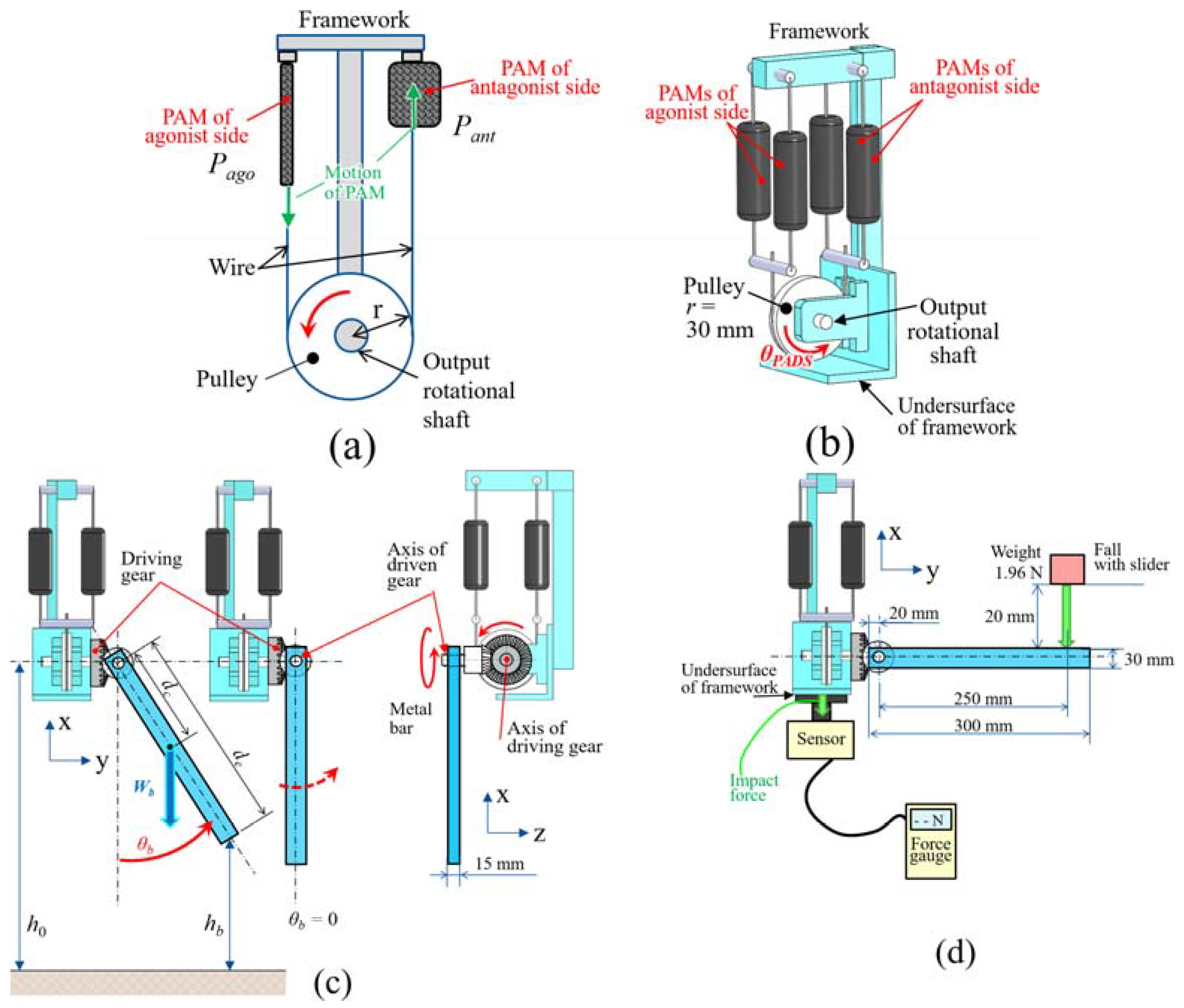
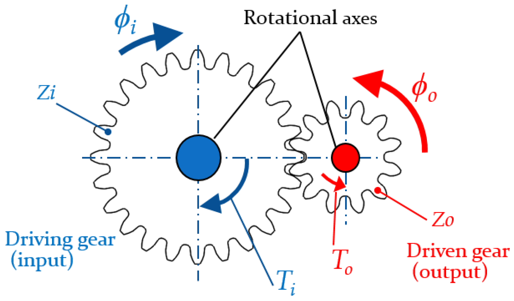
A design of the mechanism that was used in this study is shown in Figure 1. A PAM’s antagonistic drive system (PADS), as shown in Figure 1a,b, was needed to configure a rotational joint, because a PAM consists of prismatic actuators generating force by contraction only. A rotational system is necessary for various devices, such as rehabilitation devices for supporting users’ joint motions. A basic mechanism of PADS is shown in Figure 1a. The PADS was configured with PAMs that were set on the antagonist and agonist sides of a pulley. Thus, the PAM’s unidirectional translational motion can be converted into a bidirectional rotational motion of PADS by switching activation of the antagonist and agonist PAM; moreover, the rotational joint rigidity of the PADS can be changed by adjusting the air pressure (Pant and Pago) of antagonist and agonist sides as shown in Figure 1a. The influence of the changing relationship of the air pressure of both sides with respect to PADS was measured, as described later. A model of prototype of the PADS used in the experiments is shown in Figure 1b. Two PAMs were set in parallel on each side in the prototype. The pulley radius was 30 mm. An input axis (driving gear) of a speed-increasing gearbox was connected to a rotational axis at the center of the pulley. The speed-increasing gearbox is basically composed of a large (input) and small (output) gears, each having different teeth number, as shown in Figure 2. Let the teeth number of the input large gear and output small gear, input torque and rotational angle, output torque and rotation angle be Zi, Zo, Ti, ϕi, To, ϕo, in Figure 2, and To and ϕo could be represented as (1). Here, Zo/Zi means a reduction ratio Rg of the gearbox. In Figure 2, although the spur gear pair was drawn as an example of the speed-increasing gear for explicitness, a bevel gear pair was employed as the result of the mechanism layout, as described later. A metal bar made of aluminum alloy A2017 whose length and weight were 300 mm and 3.59 N, respectively, or a resin bar made of polyacetal whose length and weight were 275 mm and 0.88 N, respectively, was attached to the output axis (driven) of the gearbox, as shown in Figure 1b,c. Activating the PAMs causes the bar to rotate on the output axis. The mechanism combined with the PADS and the gearbox (denoted as the PADS-gear mechanism) with the bar was set on a force-sensitive sensor part of a force gauge (ZTA-DPU-500N, IMADA Corp., 2000 Hz, 500 N, [24]). The relationship between the ROM, torque and load, the impact and the viscoelasticity which quantify the back-drivability and compliance of the mechanism, were measured by investigating the bar’s behavior in motion, collision, and vibration experiments, described later. In this paper, ROM specifically means the rotational angle of the output axis (driven) of the gear, i.e., the bar’s angle θb of the PADS-gear mechanism, as shown in Figure 1b,c. Back-drivability (impact absorption) is defined as the effects of the speed-increasing gear for impact force and time from collision to maximum impact force in collision experiments. Moreover, the spring constant, viscous damping coefficient and damping ratio of the mechanism in vibration experiments are considered as elements of compliance.
ϕo = ϕi(Zi/Zo), To = Ti(Zo/Zi), Rg = Zo/Zi
2.2. Pneumatic Artificial Muscle (PAM)
The PAMs have a stroke-dependent output force as mentioned above. In our previous study [25], a relationship between the Mckibben-type PAM traction force Ft (N) and contraction length lc (mm), i.e., spring constant of PAM, was experimentally investigated using commercial PAM (PM-10P, SQUSE Inc., Japan, 0.003 kg, maximum pulling force 100 N, [26]). Weights 9.8–98 N were added in increments of 9.8 N to the end of three PAMs that were connected serially as shown in Figure 3, and air pressure of 0.2 MPa was applied after adding each weight, and then all PAMs were actuated. Three PAMs were used for averaging purposes. The change of length with respect to the unloaded natural length of each PAM piece, that is to say, lc, was measured under each weight, and the measurements were repeated 10 times. The resulting relational expression is shown in Equation (2). The correlation coefficient for approximation of the relationship between the Ft and lc in Figure 3d was −0.9971. Therefore, the relationship has a very strong correlation, and it was considered to be approximated by linear dependence. The output force decreased with increasing contraction. Therefore, improving the output force at a longer contraction of PAM is a challenge. In this paper, the same PAM was used.
Ft = −4.61lc + 98.02 (N)
2.3. Gearbox
The PAM traction force Ft and contraction length lc were calculated by substituting the PADS rotational angle θPADS (in degrees) in Figure 1b into Equation (3) below and using Equation (2). Here, r is the radius of the pulley as shown in Figure 1a. The output torque Tout (Nm) of the PADS-gear mechanism with the bar in Figure 1 can be calculated based on Equations (2)–(4) [25,27]. In Equation (4), Cs, Cp are the number of PAM serial and parallel connections, respectively. Rg is reduction ratio of the gear. For example, for teeth number; driving gear Zi:driven gear Zo = 2:1, Rg is 0.5. Without the speed-increasing gear (Rg = 1.0) in case of r = 30 mm, Cs = 1, Cp = 2, Tout can be calculated as shown by the solid black line in Figure 4a.
lc = 2πr·θPADS/360
Tout = RgCp(−4.61lc/Cs + 98.02)r = RgCp(−4.61(2πrθPADS/360)/Cs + 98.02)r
= RgCp(−4.61(2πrRgθb/360)/Cs + 98.02)r
= RgCp(−4.61(2πrRgθb/360)/Cs + 98.02)r
The θb without the gear could not rotate more than 40.6° because the torque dropped to zero. The air pressure of PAM was 0.2 MPa on the antagonist side (maximum) and 0 MPa on the agonist side.
A speed-increasing gear was used to improve the PADS performance. As described before, the rotational angle of PADS can increase in return for reducing the output torque as the principle of leverage. The PAM is difficult to handle because of stroke-dependent output force as shown in Figure 4a. Therefore, use of the gear generates a benefit of better handling with flatter output force characteristics throughout the ROM. Bevel gears of reduction ratio 0.5 were embedded into the PADS, as shown in Figure 1b,c. The output shaft of the gear was able to generate the torque shown by the dashed black line in Figure 4b. Although the torque output with gear (b) in Figure 4 was lower at smaller angles (27.1°), the output was higher at larger angles and the range of motion was extended. The effect appears common on the surface; however, for example, comparing an electric motor, although the speed-increasing gear improves only the rotational speed of the motor which has no limited rotation range, it reduces the torque. The PADS of (a) and the PADS-gear mechanism of (b) in Figure 4 correspond to configurations No. 2 and 4 in Table 1, respectively, described later. Moreover, in order to provide more alternatives of the reduction ratio, the performances of the PAMs with the speed-increasing gear of speed reduction ratios 0.75 and 0.25 were added to Figure 4c,d. However, the output force characteristic of (c) was considered to be not so different compared to (a). On the other hand, the maximum torque of (d) was too small (a quarter of the maximum torque of (a)) although the output force characteristic of (d) is flatter than that of (b). Therefore, the speed reduction ratio 0.5 was set as the optimal value in this paper. An additional search for the optimal solution in the speed reduction ratio is to be addressed in a subsequent project. The effect of the gear on the back-drivability, compliance, and the relationship between the range of motion and output torque were confirmed in simulations and experiments, as described below.
2.4. Simulation
The torque required to rotate the metal bar was calculated and then its ROM was simulated with and without the gear mechanism. The weight of the bar was assumed to be a concentric load acting at the center of the bar. The weight of the bar, distance between the bar center and rotational axis, and rotational angle are denoted by Wb (N), dc, and θb (in degrees), respectively (see Figure 1c). The torque required to rotate the metal bar Tb (Nm) was calculated using Equation (5). The number of PAMs in the PADS was used as a parameter for comparison, and Tout of multiple PAMs were calculated using Equation (4).
Tb = Wbdcsin(2πθb/360)
2.5. Experiment
A prototype of the mechanism in Figure 1 was made, and the ROM (rotational angle θb) of the metal bar was measured by driving the PAM. Let the height from the grounding surface of the mechanism to the axis of the driven gear and the bar end tip, and the distance between the bar end tip and rotational axis, be h0, hb and de; the ROM was derived by measuring the hb and by calculating a relational expression h0 = hb + de cos (2πθb/360), as shown in Figure 1c. Simulation and experimental results were then compared. Next, after removing once the metal bar from the output shaft of the PADS-gear mechanism, the bar was attached to the shaft horizontally after activating the PAM, and then a free-falling weight of 1.96 N collided against the end of the bar from a height of 20 mm as shown in Figure 1d. The impact force in the collision was detected by the force-sensitive sensor part of the force gauge on which the PADS-gear mechanism was placed, as shown in Figure 1d. The impact transmitted to the PADS-gear mechanism allowed for the back-drivability to be measured. The PADS with and without the speed-increasing gear were compared to investigate the effect of the speed-increasing gear. To eliminate the effect of the weight of the gearbox in the comparison, the gear of ratio 0.5 in the PADS-gear mechanism was replaced with a gear of ratio 1.0, creating a PADS of equivalent weight without the gear mechanism. Each gearbox is shown in Figure 5. Moreover, the air pressure for the PAMs was set two ways to verify its effect. The first was 0.2 MPa for the antagonistic side and 0 MPa for the agonistic side, and the second was 0.1 MPa for both sides, as shown in Figure 1b. The former means that the bar has maximum rotational torque only against one direction of initial displacement. The latter has torque in both rotational directions, meaning it is balanced. Therefore, four experimental configurations as shown in Table 1 were tested.
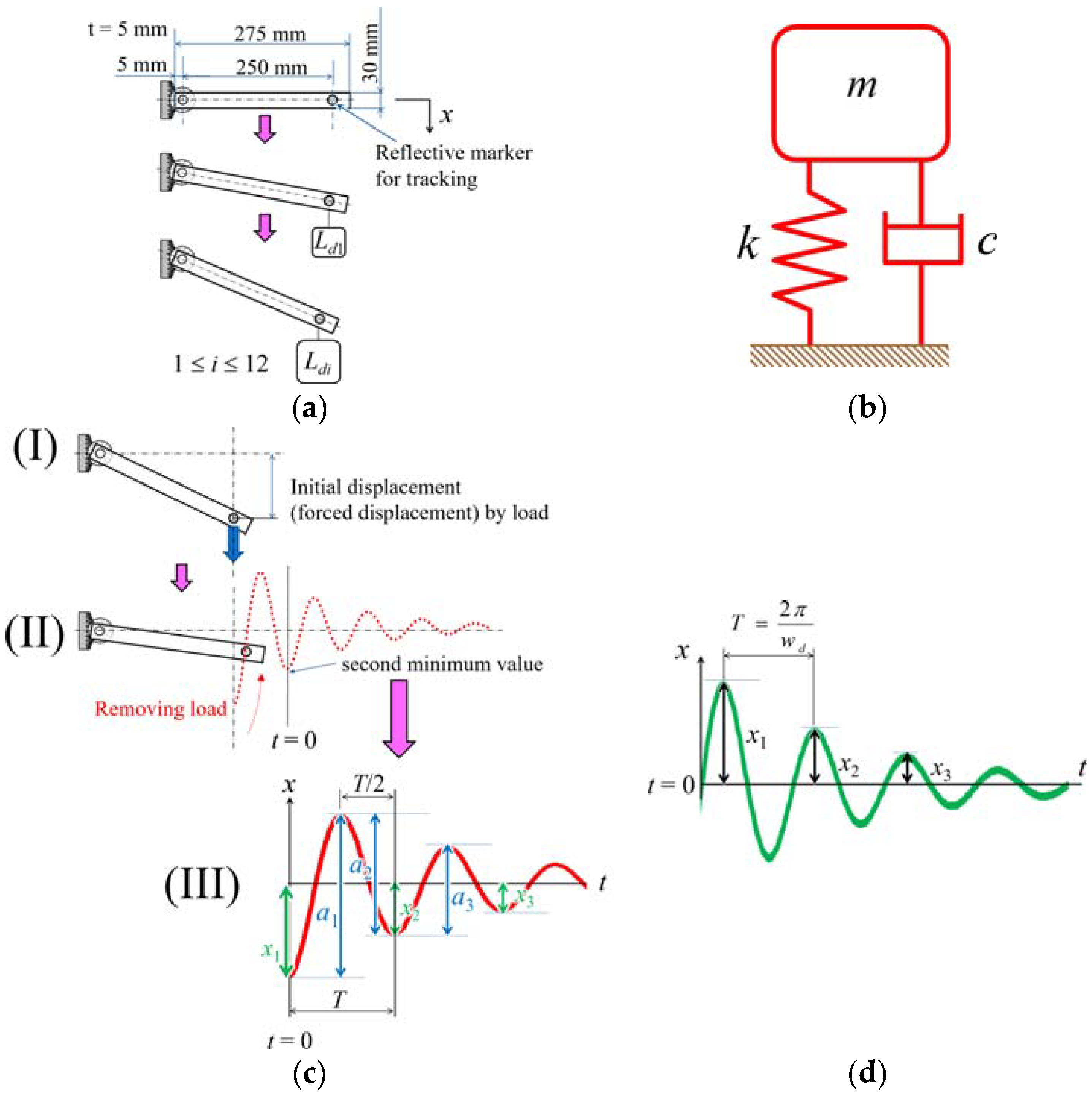
The compliance of the mechanism was also measured. The lighter resin bar was connected to the PADS-gear mechanism to lessen the effect of the bar’s weight. As shown in Figure 6a,b, we assumed that the bar was a simplified cantilever and mass system. In this paper, spring constant, viscous damping coefficient and damping ratio in vibration experiments with the mass system are considered as elements of the compliance. The spring constant k of the PADS-gear mechanism was calculated by measuring the behavior of the resin bar. As shown in Figure 6a, the resin bar was attached horizontally after activating the PAM, load Ld (0.49, 0.98, 1.47, 1.96, 2.45, 2.94, 3.43, 3.92, 4.41, 4.9, 7.35, and 9.8 N) was added at the end of the bar, and the end displacement x was measured. The spring constant was calculated from the relationship between the displacement and static load Fs (i.e., Ld) in Equation (6).
To derive the viscous damping coefficient c, an initial displacement (forced displacement) of the bar from each load based on k was applied for each configuration in Table 1, and the vibration behavior of the bar was measured after removing the load, as shown in Figure 6c. This vibration measurement was repeated 10 times for each configuration (G10P1 was only tested nine times) using a motion-tracking system (Library Co., Ltd., Tokyo, Japan) [29]. We assumed the captured waveform data were damped-free vibration. A damped-free vibration, as shown in Figure 6d, is generally represented by Equation (7) [30,31]. Here, x, t, wn, wd, and ζ, are displacement, time, natural angular frequency, damped angular frequency, and damping ratio, respectively, and C1 and σ are arbitrary constants. Because the measured waveform was considered to be as shown in Figure 6c (II), the waveform can be represented by Equation (8). Here, considering the effects of work for removing the load on the vibration, such as contact and friction, let the position of the second minimum value be t = 0 as shown in Figure 6c (II,III). Let the vibration amplitude be x1, x2, x3, …, xi in Figure 6c (III), therefore, the amplitude ratio x1/x2 for cycle T (Equation (9)) could be represented as (10). A logarithmic decrement δ is defined as the natural logarithm of the ratio of two successive amplitudes and could be obtained as (11) from (10) [30]. The amplitude ratio for any two successive amplitudes could be represented as Equation (12) by using Equations (10) and (11). Therefore, the amplitude ratio x1/xi and the logarithmic decrement δ when the vibration has repeated for i cycles are given by Equation (13). However, because the equilibrium position of the measured oscillatory waveform in the vibration experiments was difficult to be read off, therefore, a1, a2, …, ai are actually read off in Figure 6c (III). The amplitude ratio a1/a2 for a cycle T/2 could be represented as Equation (14), the logarithmic decrement δ is derived as Equation (15) from Equations (13) and (14). In this paper, δ (i = 3) are calculated in Equation (15).
The damping ratio ζ, viscous damping coefficient c, wn and wd are defined as (16)–(19), respectively [30,31]. m is mass in Figure 6b and Equations (17) and (18), and is assumed to be the mass of the resin bar, 0.09 kg (weight 0.88 N). Eventually, the behavior of all four configurations was compared and the effects of the gear and air pressure were confirmed using the measured waveform and data calculated above.
Fs = kx
3. Results
3.1. Prototype
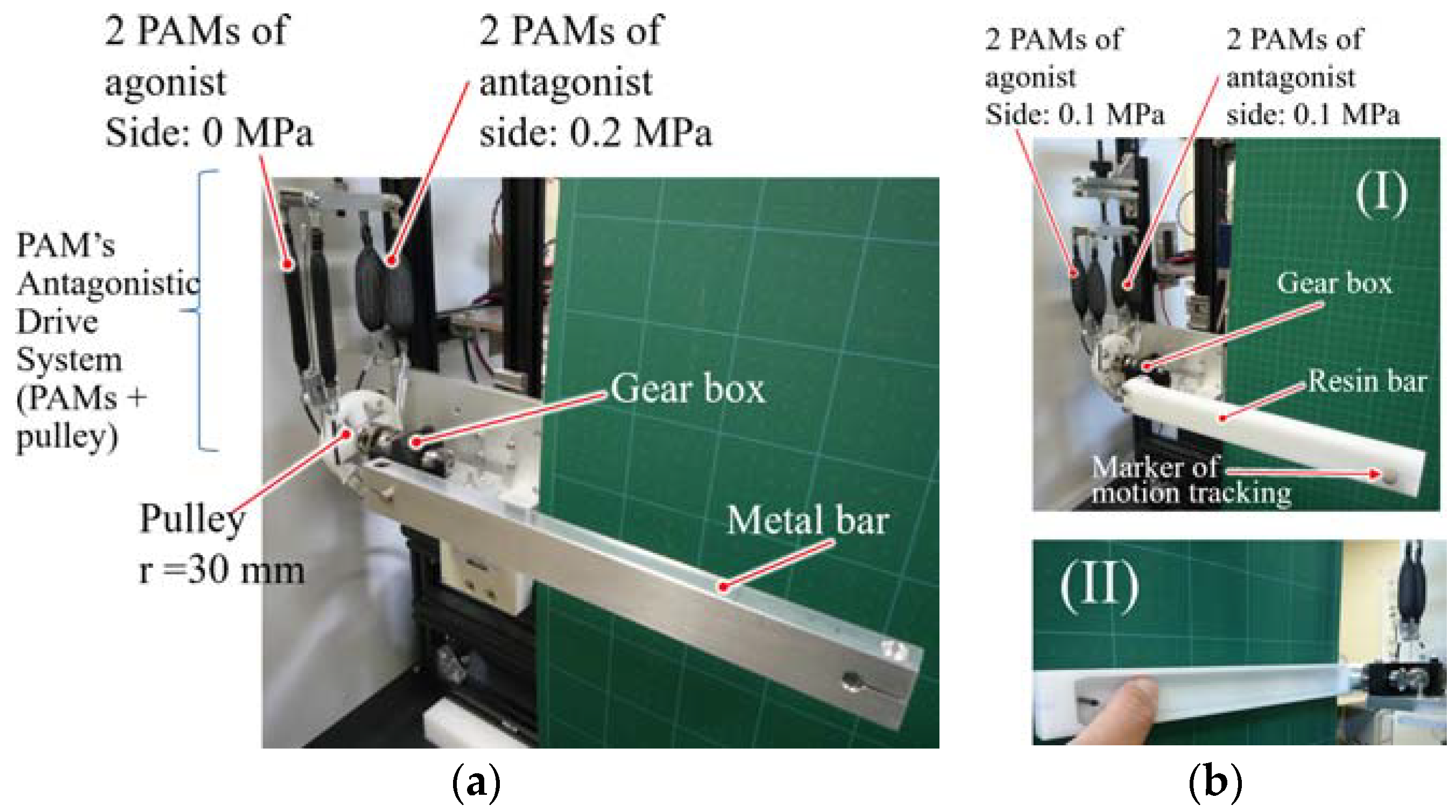
Figure 7a shows the prototype with the solid metal bar (3.59 N) for the ROM measurement and collision experiment. Figure 7b shows the prototype with the resin bar (0.88 N), which was employed in the experiment to measure the viscoelasticity. The resin bar was hollow with a plate thickness of 5 mm for weight saving, as shown in Figure 7b (II).
3.2. Simulation
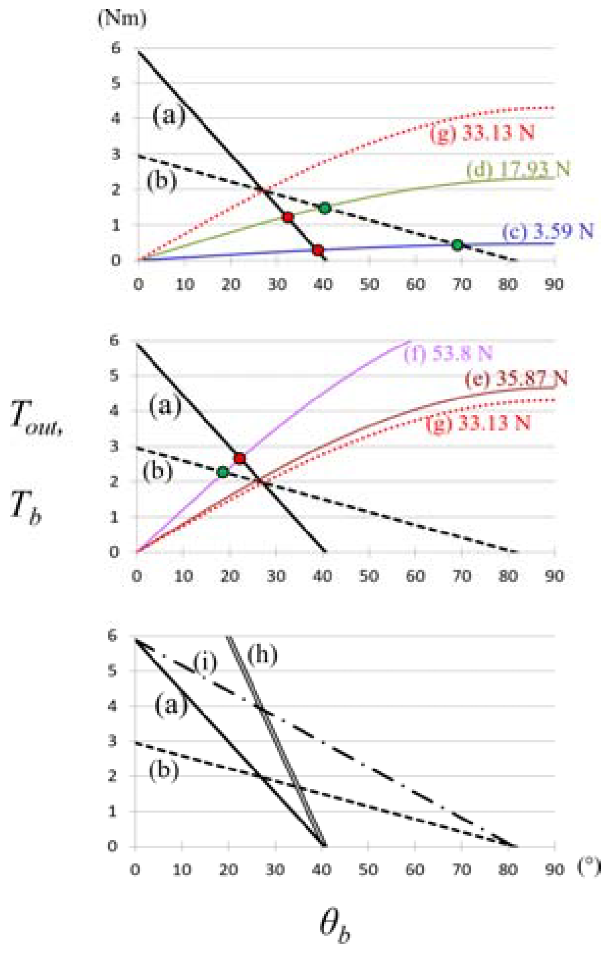
Figure 8a,b show the relationship between the output force Tout and the ROM θb for configurations G10P2 (solid black line) and G05P2 (dashed black line) of the mechanism shown in Table 1 and Figure 4. Figure 8c–f show the relationship between the required torque Tb and θb of the metal bar in Figure 1c, which was derived from Equation (5). Although the prototype metal bar weighed 3.59 N, bars with weights of 17.93 N (5 times), 35.87 N (10 times), and 53.8 N (15 times) were simulated. The simulated bars had the same dimensions as the prototype bar. Intersection points indicate the maximum rotational angle of the metal bar (3.59, 17.93, 35.87, and 53.8 N) that was reached by mechanisms G10P2 (red point) and G05P2 (green point). Figure 8g shows a curve passes through the intersection point between (a) and (b). For comparison, configurations of 4 PAMs used in parallel in G10P2 (r = 30 mm, Cs = 1, Cp = 4, Rg = 1.0 in Equation (4)), and 2 PAMs used in serial and in parallel in G10P2 (r = 30 mm, Cs = 2, Cp = 2, Rg = 1.0) are shown in Figure 8h,i, respectively.
3.3. Experiments
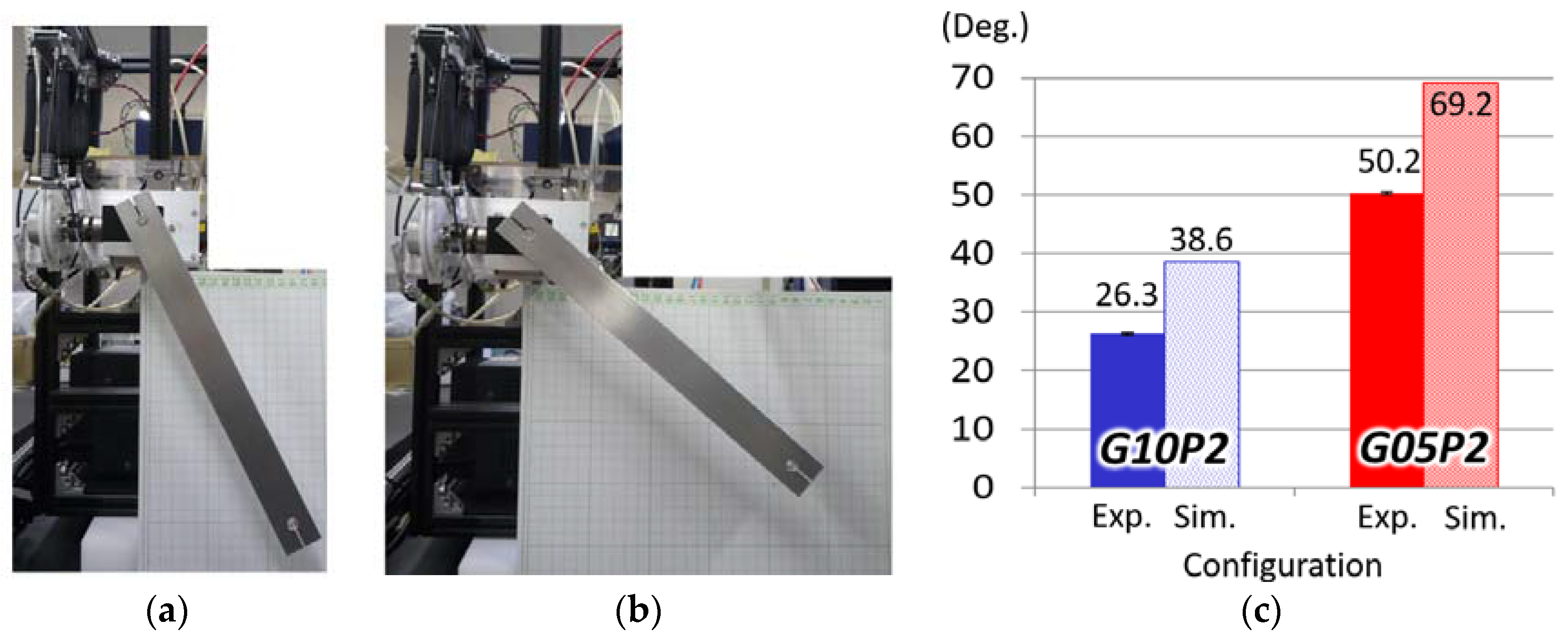
Figure 9a,b show the maximum rotational angle reached with the metal bar (3.59 N) by configurations G10P2 and G05P2, respectively. The angle at the intersection point from the simulation shown in Figure 8a–c is shown in Figure 9c for comparison between the simulation and experiments.
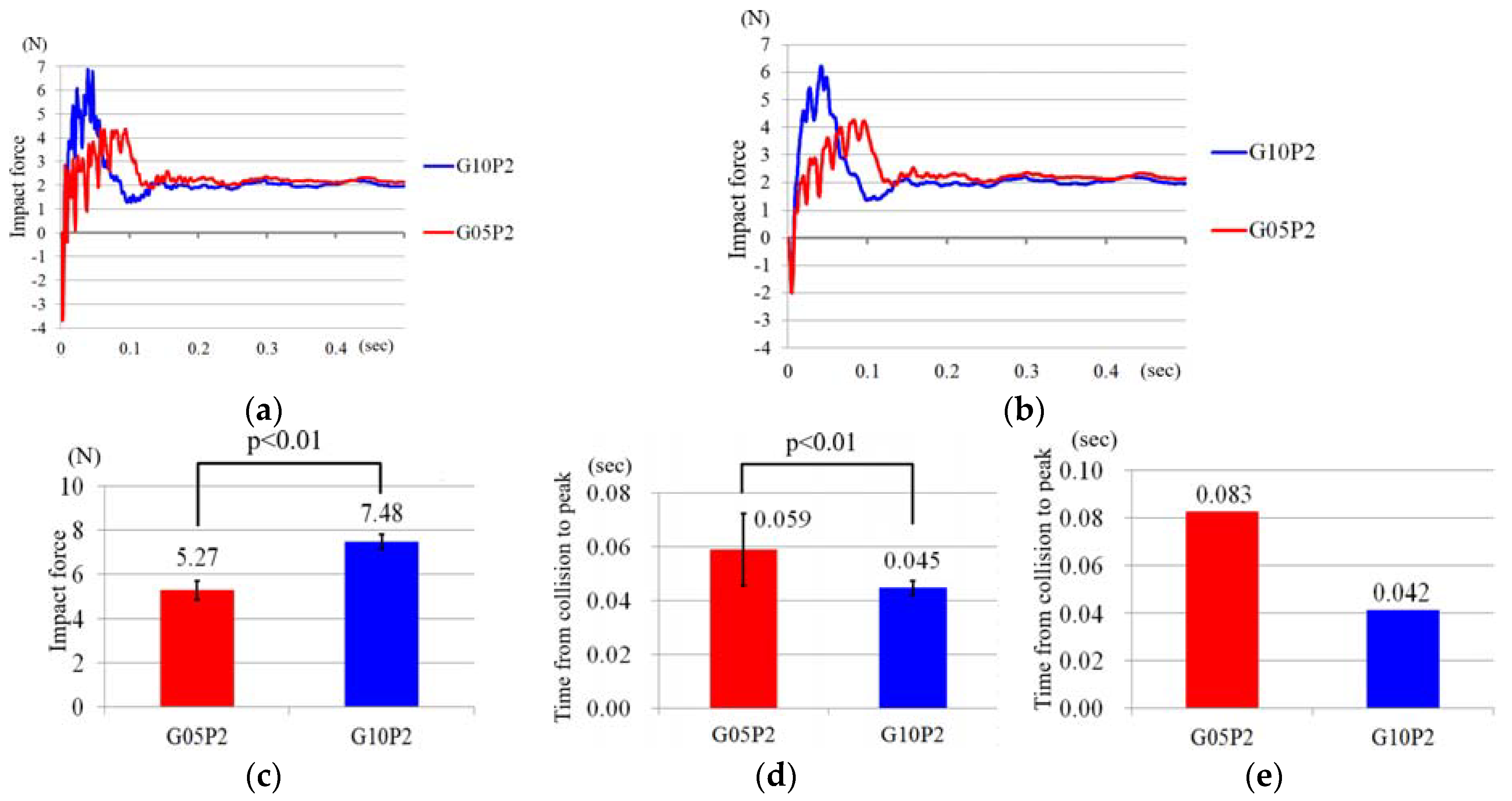
Figure 10 shows results from collision experiments for configurations G10P2 and G05P2. Figure 10a,b show changes of impact force measured by the force gauge 0.5 s after the collision. Because the impact force was measured at 2000 Hz, 1000 points are plotted. The waveforms in Figure 10a are the average values for the 10 experiments, and the waveforms in Figure 10b are smoothed using a moving average of 10 points for visibility. In Figure 10a,b, negative values were measured. This is attributed to the load cell inertia in the force gauge. Figure 10c–e show the average maximum impact force, average time from collision to maximum impact force in Figure 10a, and average time from collision to maximum impact force in the smoothed waveform in Figure 10b, respectively.
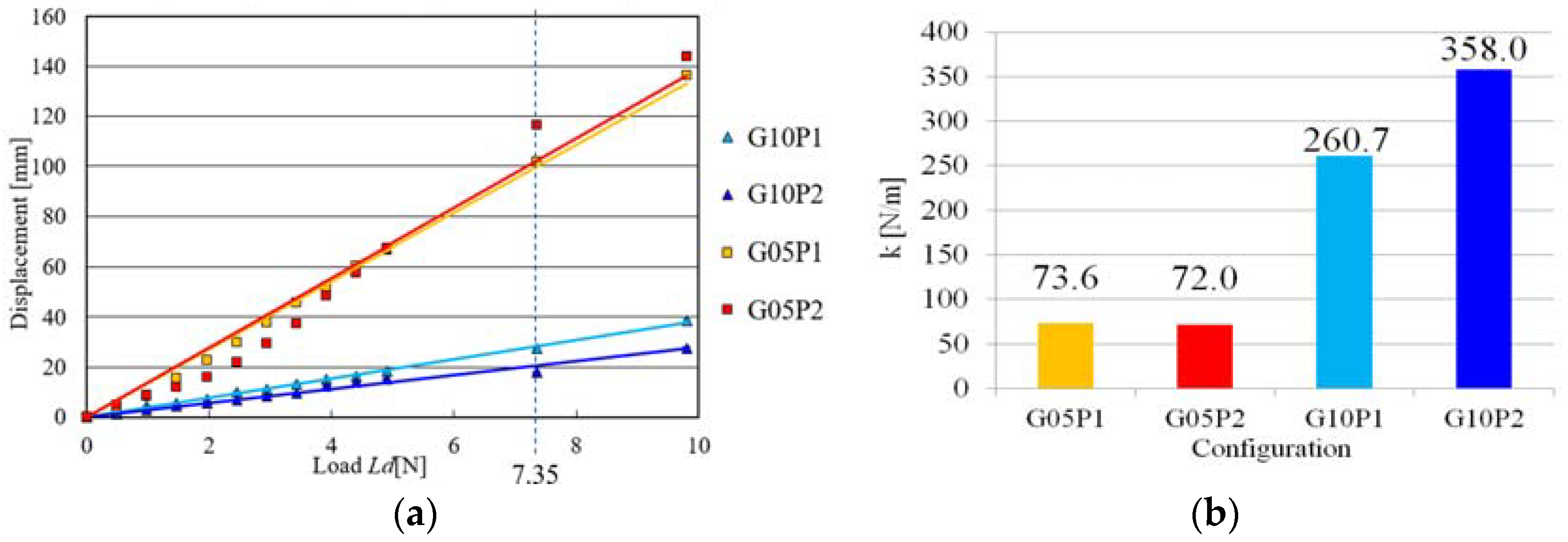
The measured spring constant k of all four configurations is shown in Figure 11. Figure 11a shows the relationship between the displacement x of the tip of the bar and static load Ld. k was calculated using the relationship in Figure 11a, Equation (6), and the least-squares method, as shown in Figure 11b.
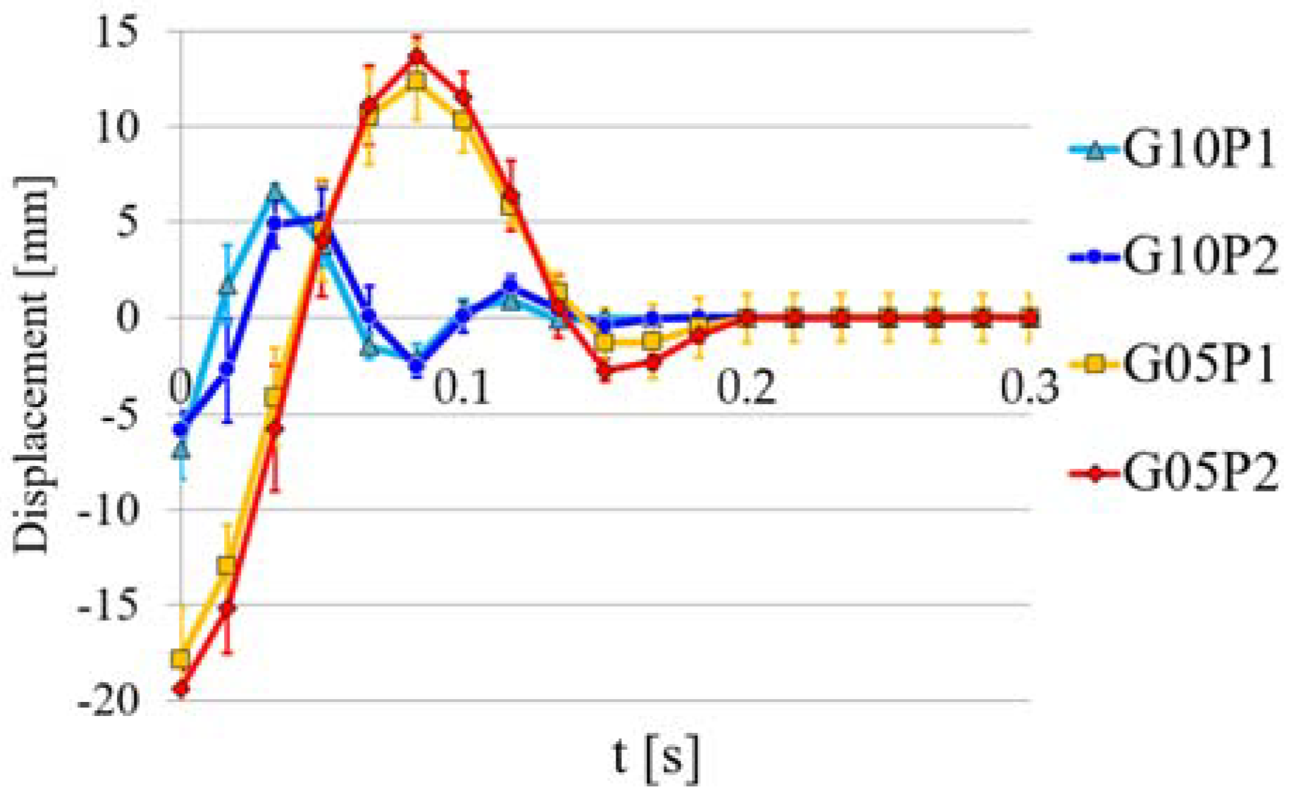
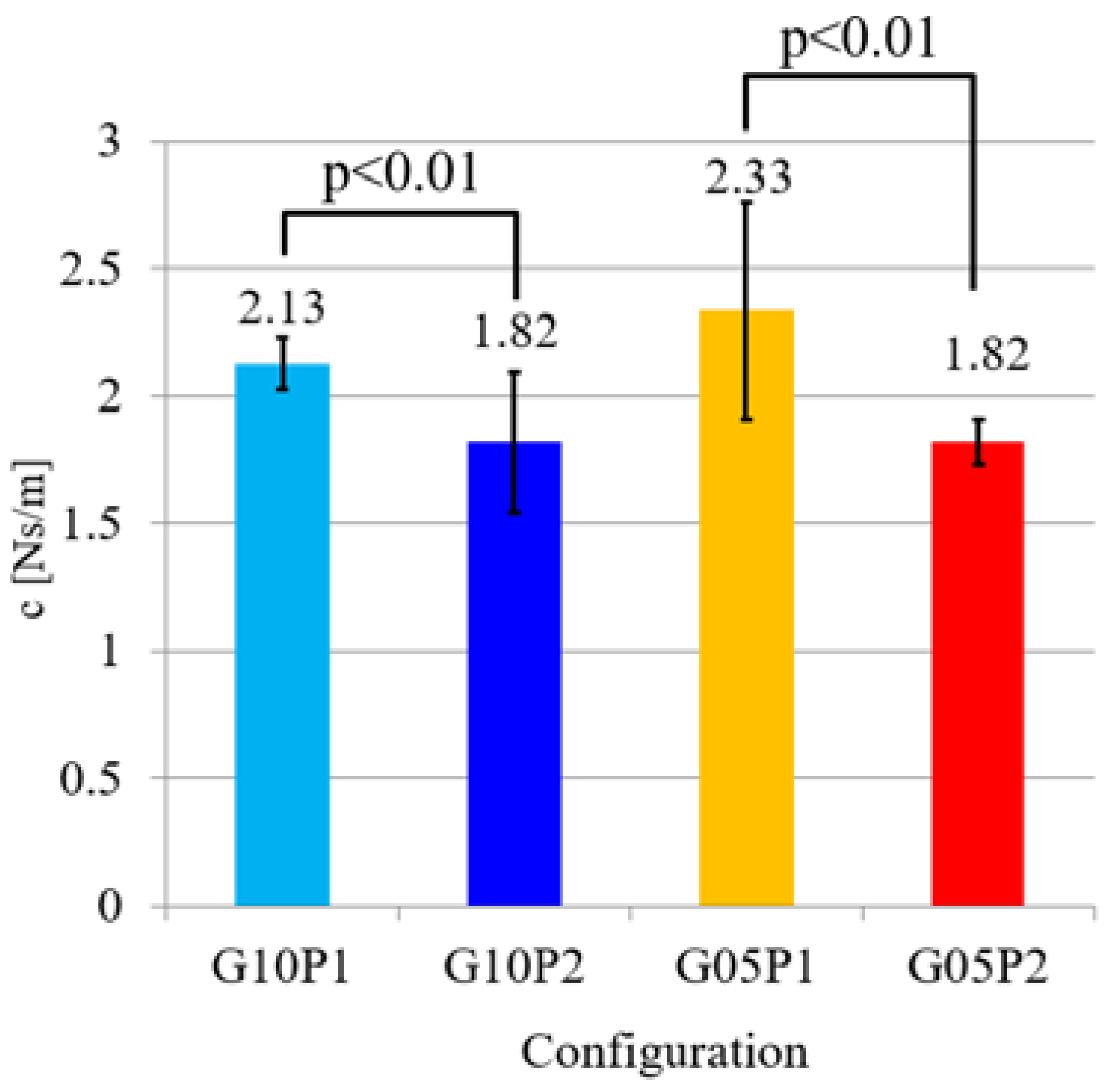
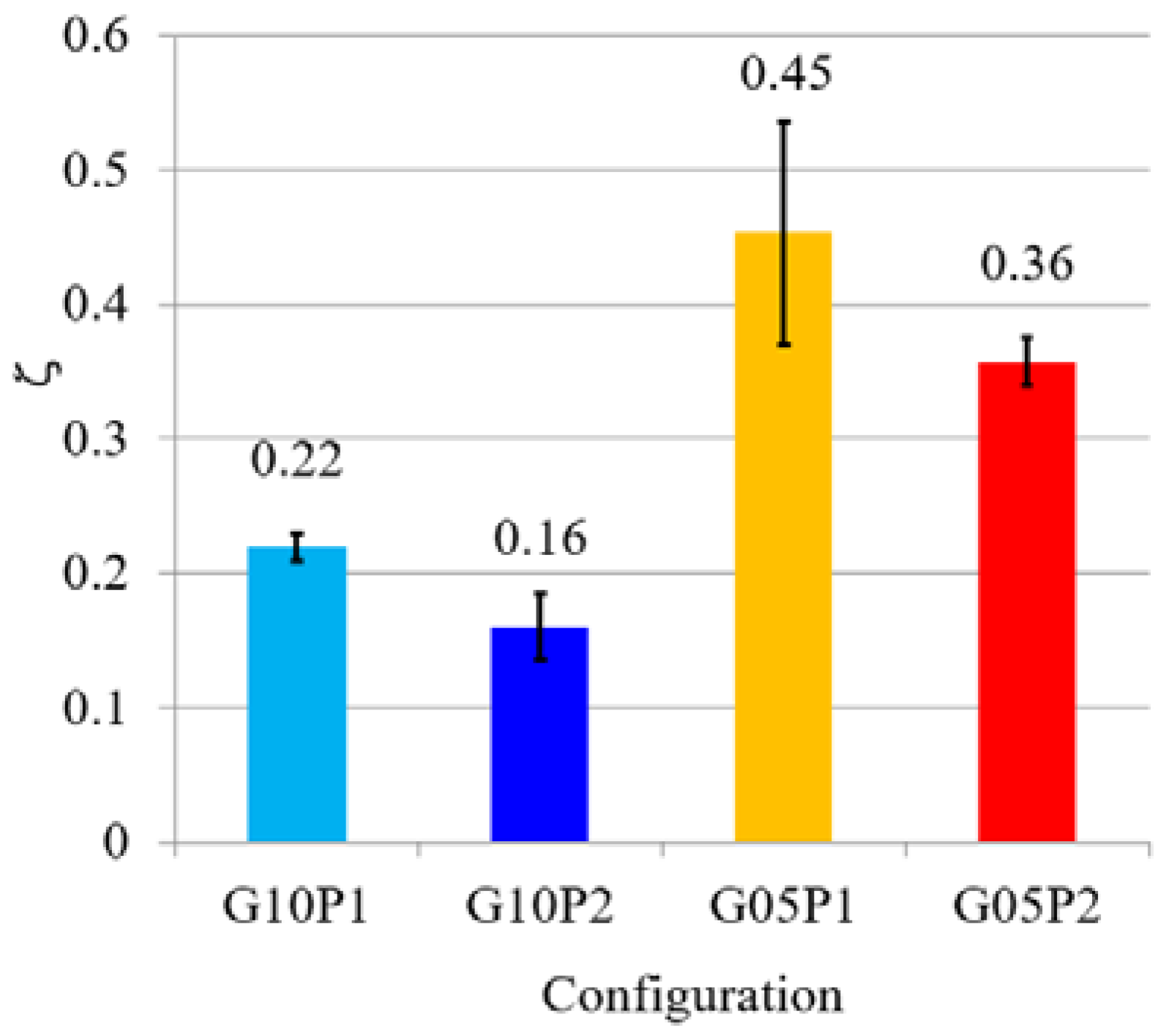
The measured vibration data (waveform) by the motion-tracking system (60 Hz), viscous damping coefficient c, damping ratio ζ, which were obtained from Equations (8)–(17) with the data, are shown in Figure 12, Figure 13 and Figure 14, respectively. For visibility, the waveforms were offset so that each convergence position of raw waveform aligns with the displacement x = 0 in Figure 12. The initial displacements for the four configurations in Figure 6c (I) were determined based on the spring constant k, and are shown in Table 2. The initial displacement was actually based on the displacement when the load Ld of 7.35 N is added as shown in Figure 11a.
4. Discussion
In the simulations and experiments, gearboxes with reduction ratios 1.0 (without the effect of the gearbox) and 0.5 were mounted into the PADS and metal or resin bars were used to evaluate their potential to improve the back-drivability, compliance and the relationship between the ROM and output force.
First, the ROM in the simulation was verified. For a bar with the same weight as the prototype (3.59 N), the ROM was improved from 38.6° to 69.2° using the gearbox with ratio 0.5 (G05P2) instead of the gearbox with ratio 1.0 (G10P2). This was determined from the intersection points between the line of PADS-gear mechanism output torque in Figure 8a,b and the curve of the required torque for the bar in Figure 8c. At this point, the output torque of G05P2 was larger than that of G10P2, therefore, both the output torque and ROM, which have a tradeoff relationship, were enhanced by the speed-increasing gear. However, in cases of the metal bar weighing 53.8 N and 35.87 N, the situation was reversed and both the ROM and torque of G05P2 were lower than those of G10P2. Therefore, the speed-increasing gear in this specification (PAM’s output force, contraction length, and pulley radius) of the PADS effectively improved the ROM and output torque below a certain load (33.13 N in Figure 8g). Therefore, when this PADS-gear mechanism is applied to other devices, it is necessary to optimize the design parameters based on the imposed load to maximize the use of the mechanism. Although four parallel connections (Cs × Cp = 1 × 4 PAMs) had larger output torque at small ROM, they were not able to enhance the ROM compared with G10P2 and G05P2, as shown in Figure 8a,b,h. On the one hand, serial connections (Cs × Cp = 2 × 2 PAMs) had a larger output and ROM as shown in Figure 8i. However, as a practical matter, the PAM’s length and diameter are about 140 mm × ϕ 10 mm (120 mm × ϕ 24 mm while pressuring), meaning PAMs connected serially are very long. Although the gearbox used in this paper was 70 mm × 70 mm × 30 mm, other commercial gears of smaller size are available. Moreover, the ROM of Figure 8b is equivalent to 8i. Considering the embedding and use of PADS in other devices, PAMs connected serially are not considered to be superior; however, the use of the gear mechanism is considered suitable as the bedding for other devices below a certain load, as described above.
The output efficiency of the PADS-gear mechanism for configurations G10P2 and G05P2, shown in Figure 9, was about 70% (26.3/38.6 = 68.1%, 50.2/69.2 = 72.5%), and this is attributed to mechanism errors derived from machining errors, assembling errors, and wire stretch, which decreased transmission efficiency. Especially, with regard to mechanism errors, PAMs used in the experiments are soft and have characteristics of hysteresis because they are made of rubber and synthetic resin fiber net. Therefore, PAMs have slight individual differences, and a natural length and shrinkage length of each PAM piece in the experiments is not precisely the same unlike standard industrial pneumatic cylinder actuators composed of rigid bodies. Two PAMs connected in parallel in Figure 7 could not contract the wire at the same timing completely, and then could not generate a traction force double that of a PAM force perfectly. Therefore, the mechanism errors including the connection of PAMs have a great influence on the differences between experimental and simulation results in Figure 9. It is necessary to improve the precision when the mechanism is applied to other devices.
G05P2 reduced the impact compared with G10P2, as shown in Figure 10. Moreover, G05P2 delayed shock transmission compared with G10P2. It is assumed that the gear of ratio 0.5 absorbs the impact while rotating through a larger angle than the gear of ratio 1.0. Therefore, when other devices that employ this PADS-gear mechanism receive an external force suddenly and unexpectedly, this feature would lessen the impact transferred to the user’s body of the devices and enhance safety. Moreover, this behavior leads to the possibility of allowing additional coping methods after collision, such as the correspondence of the control method, by reducing the transmission speed of the impact, as shown in Figure 10c,d.
The spring constant k of configurations G05P1 and G05P2 (in the following explanation, denoted as G05P1-2) were significantly different from those of G10P1-2, and this tendency was the same when the air pressure was changed, as shown in Figure 11. Although the output forces of G10P1-2 were twice those of G05P1-2, their k were about 3.5–5 times larger. This is because when a load was added to the bar (i.e., to the output shaft of the gearbox), the torque transmitted to the input shaft in the gear of G05P1-2 was twice the torque of the gear of G10P1-2. Therefore, the PAMs of G05P1-2 were pulled by double the force and stretched longer compared with G10P1-2, as shown in Equation (2). The longer stretch made the input and output shaft rotate more. In this way, G05P1-2’s displacement became significantly larger, i.e., the k became significantly smaller than G10P1-2 by the effect of both the gear ratio and PAM’s relationship between the force and contraction length.
When the vibration was measured, the initial displacement was given to the bar of each configuration, and the bar’s behavior was measured after removing the initial displacement. A comparison of each configuration when the same external force or disturbance occurred can be made. G05P1-2 were more damped compared with G10P1-2, as shown in Figure 12 and Figure 14. Therefore, G05P1-2 including the speed-increasing gear behaved more softly and slowly, thereby improving the back-drivability i.e., impact force and time from collision to maximum impact force compared with G10P1-2, which did not contain the gear mechanism. On the other hand, the viscous damping coefficient c was affected by PAM’s air pressure and was not significantly affected by the gear ratio, as shown in Figure 13. Therefore, these results showed that the gear ratio and air pressure had large effects on the external static and dynamic forces, respectively, in the PADS-gear mechanism.
5. Conclusions
In this paper, we developed the PADS-gear mechanism and verified its benefits to enhance the convenience of using PAMs as the actuator in mechanical devices interacting with humans, such as medical robotics or wearable devices. PAMs are soft and light; however, they have the disadvantage of a stroke-dependent output force, which means that PAMs cannot achieve a large ROM with high output force. On the other hand, the gear can enhance the ROM and back-drivability in exchange for output force. Simulations showed that the PADS-gear mechanism effectively improved both the ROM and output torque, which generally have a tradeoff relationship, below a certain load compared with the configuration without the gear. The PADS-gear mechanism was in no way inferior to using multiple PAMs considering both ROM and space-saving needs for other devices, which are assumed to be embedded with the PADS-gear mechanism. Moreover, the prototype showed the same effect in experiments.
In the collision and viscoelasticity experiments, the PADS-gear mechanism mitigated the impact force and responded softly and slowly to the external disturbance, which showed the possibility of improving the back-drivability. Moreover, the gear and PAM showed the effect for static and dynamic external disturbances, respectively. Therefore, using the PADS gear mechanism in devices that are involved with humans can contribute to the enhancement of their safety and affinity, and the mechanism for such devices is considered to be feasible. However, with respect to practical applications, it is necessary to investigate and solve outstanding problems such as the accuracy of the machining, control of the PAM, weight reduction, and downsizing of the mechanism.
Author Contributions
M.S. carried out the design of the study, development of the device and prototype, execution and analysis of the experiments, and was in charge of drafting the paper. R.K. performed the experiments and commented on the paper. W.Y. assisted the design of the study and the preparation of the paper.
Acknowledgments
This work was primarily supported by the Japan Society for the Promotion of Science (JSPS) Grant-in-Aid for Scientific Research (C), Grant Number 16K01537. We thank Melissa Gibbons, from Edanz Group (www.edanzediting.com/ac) for editing a draft of this manuscript.
Conflicts of Interest
The authors declare that they have no competing interests.
Abbreviations
| PAM | Pneumatic artificial muscle |
| ROM | Range of motion |
| SMA | Shape memory alloys |
| PADS | PAM’s antagonistic drive system |
| PADS-gear mechanism | Mechanism combined with PADS and gearbox |
| Zi | Teeth number of input large gear |
| Zo | Teeth number of output small gear |
| Ti | Input torque of gear box |
| To | Output torque of gear box |
| ϕi | Input rotational angle of gear box |
| ϕo | Output rotational angle of gear box |
| Ft | Traction force |
| lc | Contraction length |
| Rg | Reduction ratio of gear |
| Tout | Output torque of PADS-gear mechanism |
| Cs | Number of PAM serial connections |
| Cp | Number of PAM parallel connections |
| r | Pulley radius |
| θPADS | Rotational angle of PADS (in degrees) |
| Wb | Weight of bar |
| dc | Distance between bar center and rotational axis |
| θb | Rotational angle of bar (in degrees) |
| Tb | Required torque for rotating bar |
| c | Viscous damping coefficient |
| k | Spring constant |
| Ld | Load |
| x | Displacement of bar end tip |
| Fs | Static load |
| t | Time |
| wn | Natural angular frequency |
| wd | Damped angular frequency |
| ζ | Damping ratio |
| C1 and σ | Arbitrary constants |
| δ | Logarithmic decrement |
| m | Mass |
| T | Cycle time |
| G05P1-2 | G05P1 and G05P2 |
| G10P1-2 | G10P1 and G10P2 |
References
- Jiang, F.; Tao, G.; Li, Q. Analysis and control of a parallel lower limb based on pneumatic artificial muscles. Adv. Mech. Eng. 2017, 9, 1–14. [Google Scholar] [CrossRef]
- Aguilar-Sierra, H.; Yu, W.; Salazar, S.; Lopez, R. Design and control of hybrid actuation lower limb exoskeleton. Adv. Mech. Eng. 2015, 76, 1–13. [Google Scholar] [CrossRef]
- Mizuno, T.; Tsujiuchi, N.; Koizumi, T.; Nakamura, Y.; Sugiura, M. Spring-damper model and articulation control of pneumatic artificial muscle actuators. In Proceedings of the 2011 IEEE International Conference on Robotics and Biomimetics, Karon Beach, Thailand, 7–11 December 2011; pp. 1267–1272. [Google Scholar]
- Ahmad Sharbafi, M.; Shin, H.; Zhao, G.; Hosoda, K.; Seyfarth, A. Electric-Pneumatic Actuator: A New Muscle for Locomotion. Actuators 2017, 6, 30. [Google Scholar] [CrossRef]
- Martens, M.; Boblan, I. Modeling the Static Force of a Festo Pneumatic Muscle Actuator: A New Approach and a Comparison to Existing Models. Actuators 2017, 6, 33. [Google Scholar] [CrossRef]
- Davis, S.; Caldwell, D.G. pneumatic Muscle Actuators for Humanoid applications–Sensor and Valve Integration, Humanoid Robots. In Proceedings of the 6th IEEE-RAS International Conference, Genova, Italy, 4–6 December 2006; pp. 456–461. [Google Scholar]
- Zhong, J.; Fan, J.; Zhu, Y.; Zhao, J.; Zhai, W. One nonlinear PID control to improve the control performance of a manipulator actuated by a pneumatic muscle actuator. Adv. Mech. Eng. 2014, 6, 172782. [Google Scholar] [CrossRef]
- Zhong, J.; Fan, J.; Zhu, Y.; Zhao, J.; Zhai, W. Static modeling for commercial braided pneumatic muscle actuators. Adv. Mech. Eng. 2014, 6, 425217. [Google Scholar] [CrossRef]
- Erin, O.; Pol, N.; Valle, L.; Park, Y.L. Design of a bio-inspired pneumatic artificial muscle with self-contained sensing. In Proceedings of the 38th Annual International Conference of the IEEE Engineering in Medicine and Biology Society (EMBC’16), Orlando, FL, USA, 16–20 August 2016; pp. 2115–2119. [Google Scholar]
- Plettenburg, D. Pneumatic actuators: A comparison of energy-to-mass ratios. In Proceedings of the 2005 IEEE 9th International Conference on Rehabilitation Robotics (ICORR2005), Chicago, IL, USA, 28 June–1 July 2005; pp. 545–549. [Google Scholar]
- Peerdeman, B.; Smit, G.; Stramigioli, S.; Plettenburg, D.; Misra, S. Evaluation of pneumatic cylinder actuators for hand prostheses. In Proceedings of the 4th IEEE RAS EMBS International Conference on Biomedical Robotics and Biomechatronics (BioRob), Rome, Italy, 24–27 June 2012; pp. 1104–1109. [Google Scholar]
- Garcia, E.; Arevalo, J.C.; Sanchez, F.; Sarria, J.F.; Gonzalez-de-Santos, P. Design and development of a biomimetic leg using hybrid actuators. In Proceedings of the 2011 IEEE/RSJ International Conference on Intelligent Robots and Systems (IROS), San Francisco, CA, USA, 25–30 September 2011; pp. 1507–1512. [Google Scholar]
- Oh, J.S.; Shin, Y.J.; Koo, H.W.; Kim, H.C.; Park, J.; Choi, S.B. Vibration control of a semi-active railway vehicle suspension with magneto-rheological dampers. Adv. Mech. Eng. 2016, 8, 1–13. [Google Scholar] [CrossRef]
- Xu, B.; Peng, S.; Song, A.; Yang, R.; Pan, L. Robot-aided upper-limb rehabilitation based on motor imagery EEG. Int. J. Adv. Robot. Syst. 2011, 8, 88–97. [Google Scholar] [CrossRef]
- Aggogeri, F.; Pellegrini, N. Design and experimental validation of a shape memory alloy actuator for linear motors. Appl. Mech. Mater. 2015, 783, 69–75. [Google Scholar] [CrossRef]
- Kaplanoglu, E. Design of shape memory alloy-based and tendon-driven actuated fingers towards a hybrid anthropomorphic prosthetic hand. Int. J. Adv. Robot. Syst. 2012, 9, 77. [Google Scholar] [CrossRef]
- Borboni, A.; Aggogeri, F.; Pellegrini, N.; Faglia, R. Innovative modular SMA actuator. Adv. Mater. Res. 2012, 590, 405–410. [Google Scholar] [CrossRef]
- Wang, T.; Ge, L.; Gu, G. Programmable design of soft pneu-net actuators with oblique chambers can generate coupled bending and twisting motions. Sens. Actuators A Phys. 2018, 271, 131–138. [Google Scholar] [CrossRef]
- Gu, G.Y.; Zhu, J.; Zhu, L.M.; Zhu, X. A survey on dielectric elastomer actuators for soft robots. Bioinspir. Biomim. 2017, 12, 1–22. [Google Scholar] [CrossRef]
- Marhanani, C.; Widyotriatmo, A.; Suprijanto. Free regressor adaptive impedance control for arm rehabilitation robot. In Proceedings of the 2016 International Conference on Instrumentation, Control and Automation (ICA), Bandung, Indonesia, 29–31 August 2016; pp. 76–80. [Google Scholar]
- Li, Z.; Huang, Z.; He, W.; Su, C.Y. Adaptive impedance control for an upper limb robotic exoskeleton using biological signals. IEEE Trans. Ind. Electron. 2017, 64, 1664–1674. [Google Scholar] [CrossRef]
- Morales, R.; Badesa, F.J.; García-Aracil, N.; Sabater, J.M.; Pérez-Vidal, C. Pneumatic robotic systems for upper limb rehabilitation. Med. Biol. Eng. Comput. 2011, 49, 1145–1156. [Google Scholar] [CrossRef] [PubMed]
- Ishida, T.; Takanishi, A. A robot actuator development with high backdrivability. In Proceedings of the 2006 IEEE Conference on Robotics, Automation and Mechatronics (RAM2006), Bangkok, Thailand, 7–9 June 2006; pp. 1–6. [Google Scholar]
- IMADA Co. Ltd. ZTA-DPU-500N. Available online: http://www.forcegauge.net/en/new-products/20109.html (accessed on 3 April 2018).
- Sekine, M.; Kita, K.; Yu, W. Designing and testing lightweight shoulder prostheses with hybrid actuators for movements involved in typical activities of daily living and impact absorption. Med. Devices Evid. Res. 2015, 8, 279–294. [Google Scholar] [CrossRef] [PubMed]
- SQUSE. PM-10P. Available online: http://www.squse.co.jp/product/detail.php?id=9 (accessed on 3 April 2018). (In Japanese).
- Sekine, M.; Shiota, K.; Kita, K.; Namiki, A.; Yu, W. A lightweight shoulder prosthesis with antagonistic impact-absorbing hybrid actuation for bimanual activities of daily living. Adv. Mech. Eng. 2016, 8, 1–17. [Google Scholar] [CrossRef]
- Kyouiku Gear MFG Co., Ltd. Available online: http://www.kggear.co.jp/ (accessed on 11 May 2018). (In Japanese).
- Library Co., Ltd. Available online: http://www.library-japan.com/ (accessed on 3 April 2018).
- Thomson, W.T. Theory of Vibration with Applications; CRC Press: Boca Raton, FL, USA, 1996. [Google Scholar]
- Koay, L.K.; Ratnam, M.M.; Gitano-Briggs, H. An Approach for Nonlinear Damping Characterization for Linear Optical Scanner. Exp. Tech. 2015, 39, 38–46. [Google Scholar] [CrossRef]
Figure 1.
Overview of the pneumatic artificial muscle’s (PAM’s) antagonistic drive system (PADS) gear mechanism: (a) Basic model of PADS including the pulley and PAMs; (b) model of PADS prototype; (c) the PADS-gear mechanism with the bar. The range of motion (ROM) of the mechanism (rotational angle θb of bar) was measured while activating the PAM; (d) condition of the metal bar after activation for impact test. Impact transmitted to the mechanism was measured while adding load to the bar.

Figure 2.
Basic structure of speed-increasing gear.

Figure 3.
Measurement of the relationship between the PAM traction force Ft and contraction length lc: (a) without weight and before activation (natural length); (b) loading weight and before activation; (c) loading weight with activation. Blue arrow is contraction length of 3 PAMs; (d) results of relationship.

Figure 4.
Relationship between the PADS output torque Tout and the ROM θb: (a) without gear; (b) with gears of reduction ratio 0.5. Tout of (a,b) is reversed more than 27.1°; (c) with gears of reduction ratio 0.75; (d) with gears of reduction ratio 0.25.
Figure 4.
Relationship between the PADS output torque Tout and the ROM θb: (a) without gear; (b) with gears of reduction ratio 0.5. Tout of (a,b) is reversed more than 27.1°; (c) with gears of reduction ratio 0.75; (d) with gears of reduction ratio 0.25.

Figure 5.
Bevel gear boxes (BE70L-002B and BE70L-001B, Kyouiku Gear MFG Co., Ltd., Tokyo, Japan [28]): (a) reduction ratio 0.5 (teeth number; driving gear (input): driven gear (output) = 2:1), 0.165 kg. (b) reduction ratio 1.0 (teeth number; driving gear (input): driven gear (output) = 1:1), 0.17 kg.

Figure 6.
Measurement of viscoelasticity: (a) measurement of the spring constant k with a cantilever model and static load; (b) mass system model; (c) damped-free vibration. The viscoelasticity was calculated by measuring the behavior of the resin bar. An initial displacement (forced displacement) of the bar from each load was applied (I), and the vibration behavior of the bar was measured after removing the load as red dashed line (II). a1, a2, a3 are actually read off (III); (d) a damped-free vibration generally represented by Equation (7).

Figure 7.
Prototype: (a) PADS-gear mechanism of configuration G05P2 with the metal bar; (b) PADS-gear mechanism of configuration G10P1 with the resin bar (I). Back side of the resin bar (II).
Figure 7.
Prototype: (a) PADS-gear mechanism of configuration G05P2 with the metal bar; (b) PADS-gear mechanism of configuration G10P1 with the resin bar (I). Back side of the resin bar (II).

Figure 8.
Relationship between torque and ROM: (a) G10P2; (b) G05P2; (c–f) relationship between the required torque and rotational angle of metal bars with weights 3.59–53.8 N; (g) relationship between the required torque and rotational angle of metal bar with weight 33.13 N. This curve passes through the intersection point between (a) G10P2 and (b) G05P2; (h) 4 PAMs used in parallel in G10P2 (r = 30 mm, Cs = 1, Cp = 4, Rg = 1.0 in Equation (4)); (i) 2 PAMs used in serial and in parallel in G10P2 (r = 30 mm, Cs = 2, Cp = 2, Rg = 1.0 in Equation (4)).

Figure 9.
Maximum rotational angle θb in experiments and simulations: (a) behavior of the metal bar in G10P2; (b) behavior of the metal bar in G05P2; (c) comparison between maximum θb of G10P2 and G05P2 from experiment and simulation.
Figure 9.
Maximum rotational angle θb in experiments and simulations: (a) behavior of the metal bar in G10P2; (b) behavior of the metal bar in G05P2; (c) comparison between maximum θb of G10P2 and G05P2 from experiment and simulation.

Figure 10.
Results of collision experiments for configurations G10P2 and G05P2: (a) changes of impact force; (b) smoothed changes of impact force; (c) average maximum impact force; (d) average time from collision to maximum impact force in (a); (e) average time from collision to maximum impact force in smoothed waveform (b).

Figure 11.
Measurement of spring constant k: (a) relationship between displacement x of the bar and static load Ld for four configurations; (b) k calculated using results shown in (a), Equation (6), and the least-squares method.
Figure 11.
Measurement of spring constant k: (a) relationship between displacement x of the bar and static load Ld for four configurations; (b) k calculated using results shown in (a), Equation (6), and the least-squares method.

Figure 12.
The measured vibration data (waveform) by the motion-tracking system; the time-base origin is corresponds to the position t = 0 in Figure 6c (II,III).
Figure 12.
The measured vibration data (waveform) by the motion-tracking system; the time-base origin is corresponds to the position t = 0 in Figure 6c (II,III).

Figure 13.
Viscous damping coefficient c.

Figure 14.
Damping ratio ζ.


Table 1.
Configurations for experiments.
| Configuration | Gear Ratio | Air Pressure (MPa) | ||
|---|---|---|---|---|
| No. | Name | Antagonist Side | Agonist Side | |
| 1 | G10P1 | 1 | 0.1 | 0.1 |
| 2 | G10P2 | 1 | 0.2 | 0 |
| 3 | G05P1 | 0.5 | 0.1 | 0.1 |
| 4 | G05P2 | 0.5 | 0.2 | 0 |
Table 2.
Initial displacement for vibration experiment: The initial displacement is determined based on the value where the load Ld of 7.35 N is added for each configuration, as shown in Figure 11a.
Table 2.
Initial displacement for vibration experiment: The initial displacement is determined based on the value where the load Ld of 7.35 N is added for each configuration, as shown in Figure 11a.
| Configuration | Initial Displacement (mm) | |
|---|---|---|
| No. | Name | |
| 1 | G10P1 | 27 |
| 2 | G10P2 | 18 |
| 3 | G05P1 | 102 |
| 4 | G05P2 | 117 |
© 2018 by the authors. Licensee MDPI, Basel, Switzerland. This article is an open access article distributed under the terms and conditions of the Creative Commons Attribution (CC BY) license (http://creativecommons.org/licenses/by/4.0/).
Share and Cite
MDPI and ACS Style
Sekine, M.; Kokubun, R.; Yu, W. Investigating the Effect of a Mechanism Combined with a Speed-Increasing Gear and a Pneumatic Artificial Muscle. Actuators 2018, 7, 22. https://doi.org/10.3390/act7020022
AMA Style
Sekine M, Kokubun R, Yu W. Investigating the Effect of a Mechanism Combined with a Speed-Increasing Gear and a Pneumatic Artificial Muscle. Actuators. 2018; 7(2):22. https://doi.org/10.3390/act7020022
Chicago/Turabian StyleSekine, Masashi, Ryohei Kokubun, and Wenwei Yu. 2018. "Investigating the Effect of a Mechanism Combined with a Speed-Increasing Gear and a Pneumatic Artificial Muscle" Actuators 7, no. 2: 22. https://doi.org/10.3390/act7020022
Note that from the first issue of 2016, this journal uses article numbers instead of page numbers. See further details here.