The Morphometry of the Deep-Water Sinuous Mendocino Channel and the Immediate Environs, Northeastern Pacific Ocean


Abstract
:1. Introduction
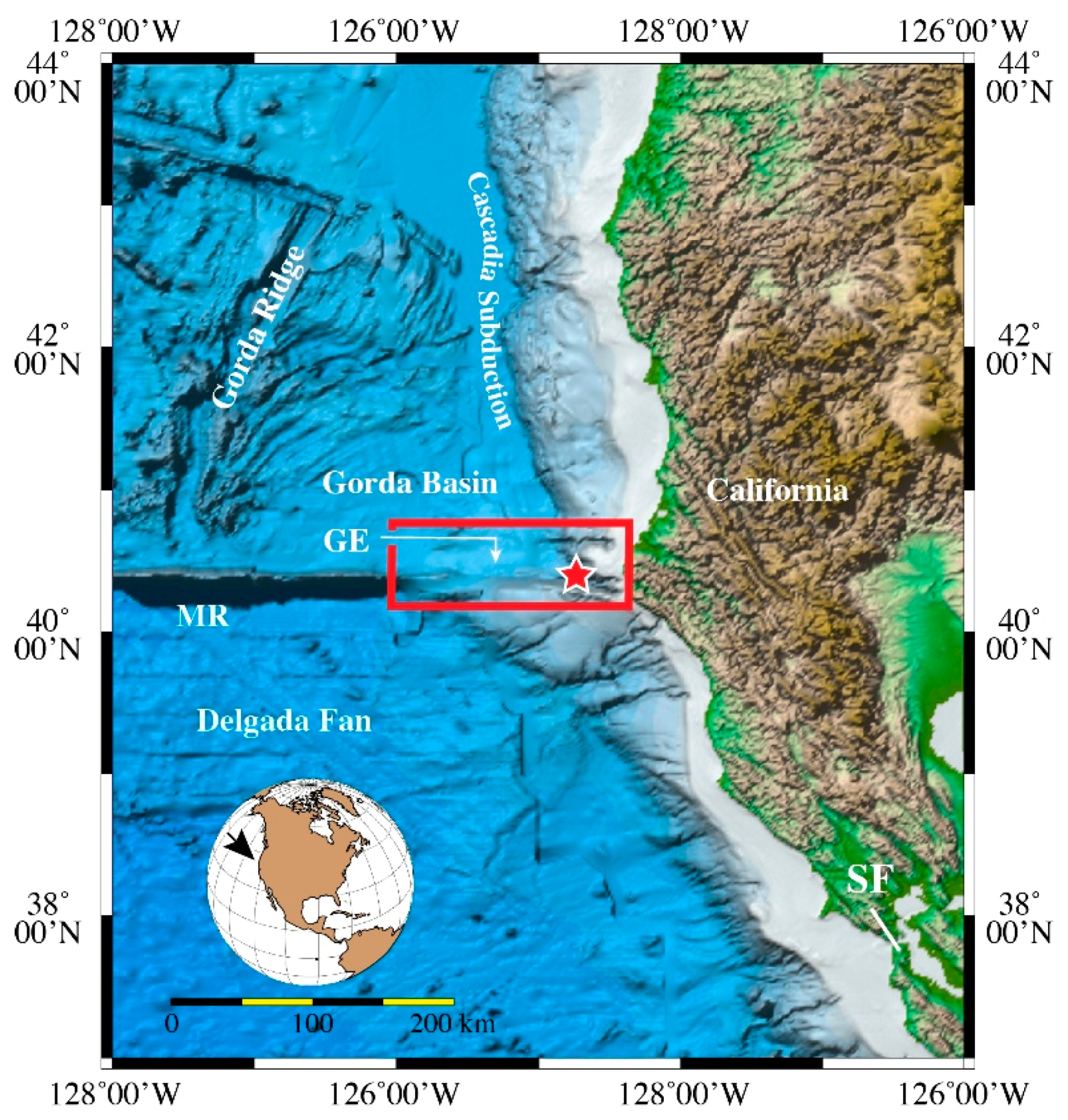
2. General Setting
3. Multibeam Echosounder Data
4. Channel Descriptions
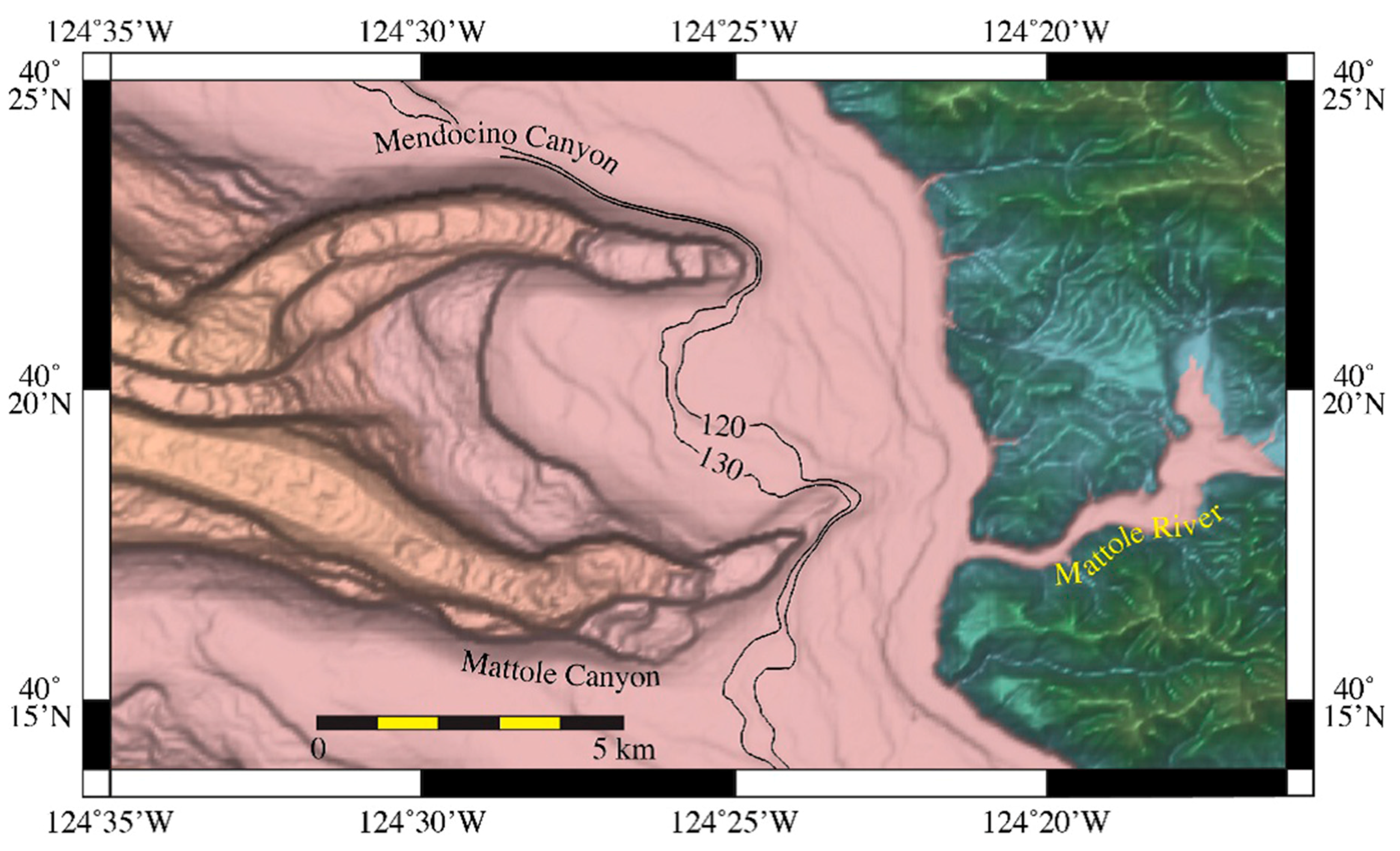
4.1. Mendocino and Mattole Canyon Channels
4.2. Mendocino Channel Upper Straight Reach
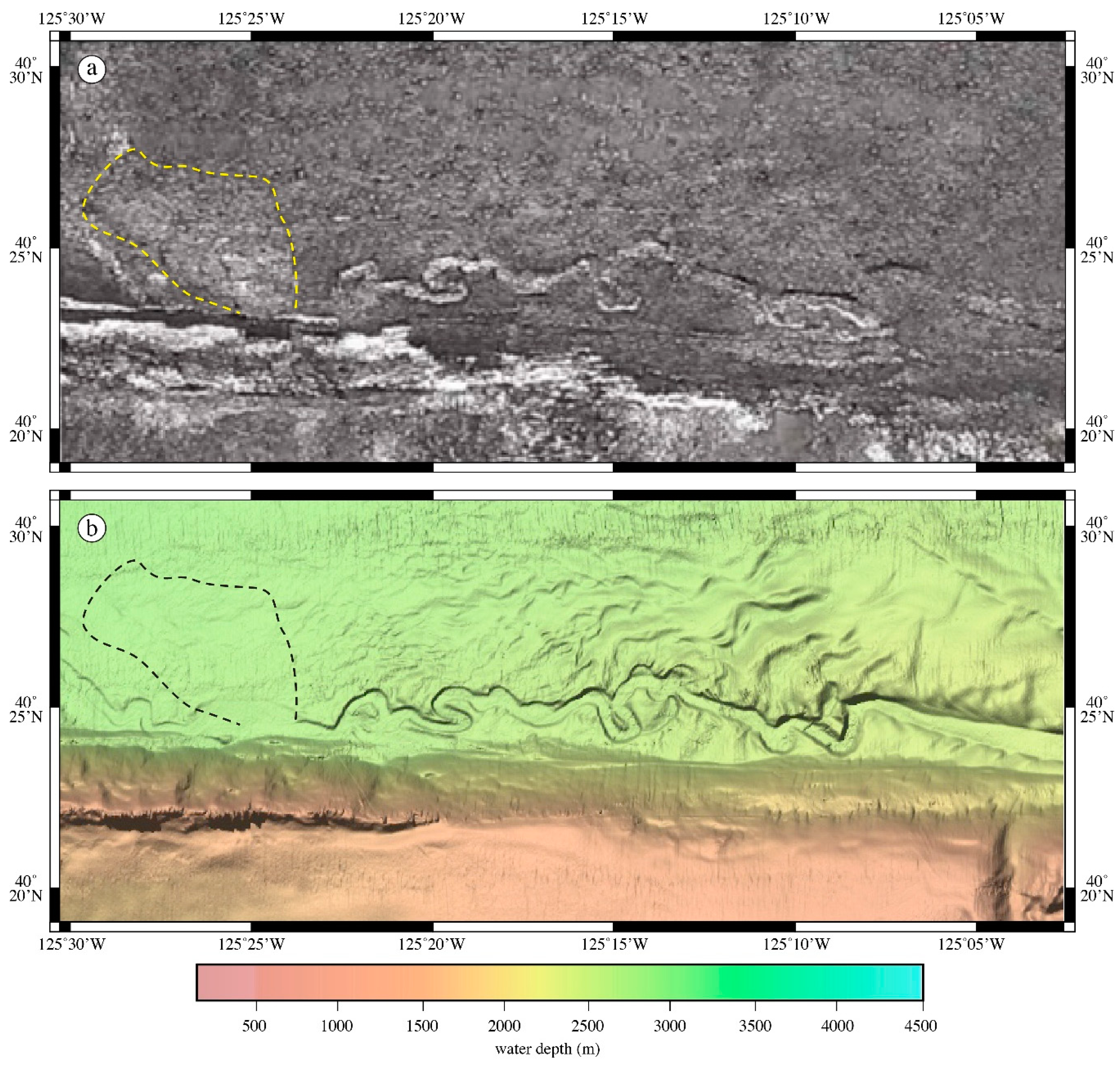
4.3. Mendocino Channel Upper Sinuous Reach
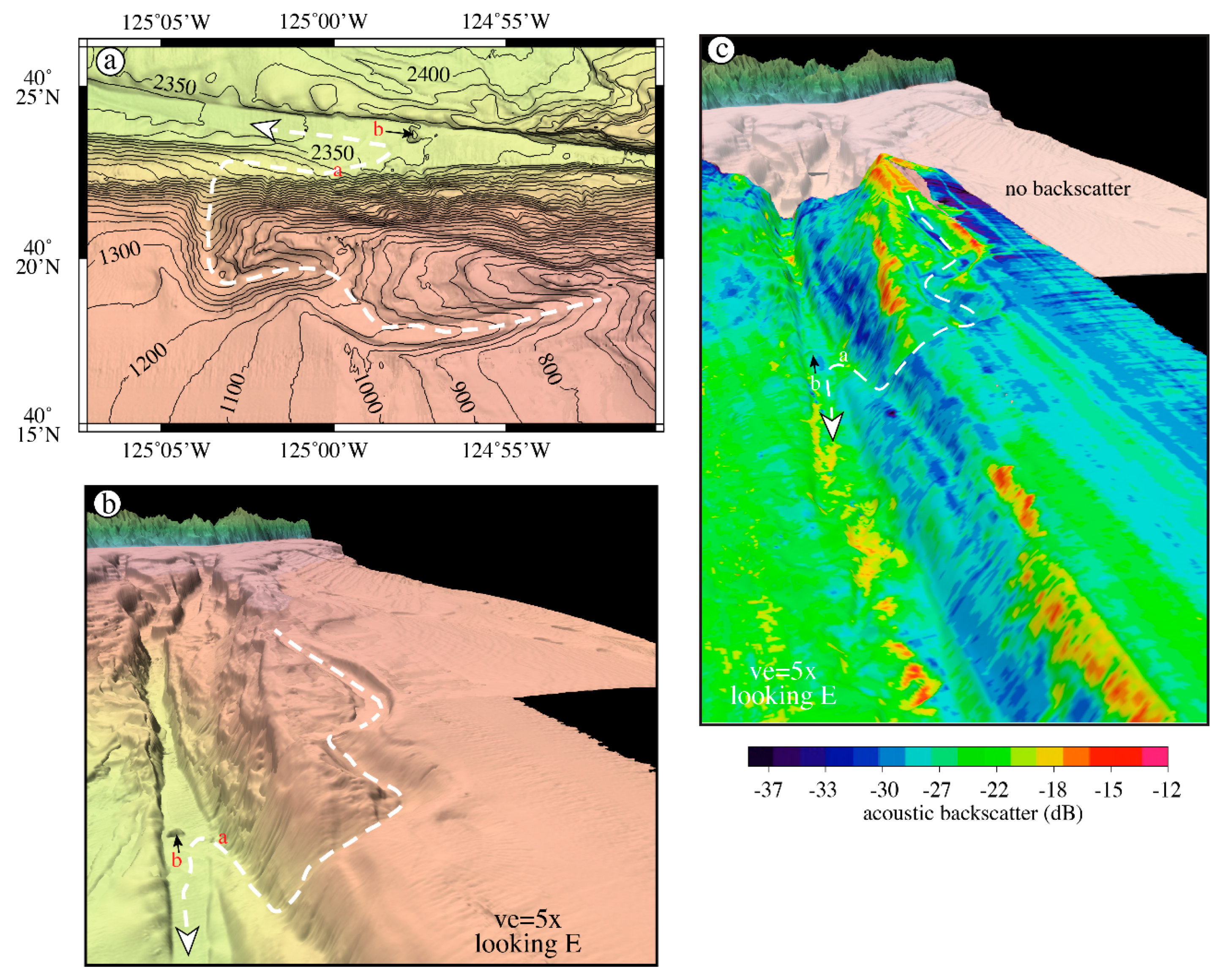
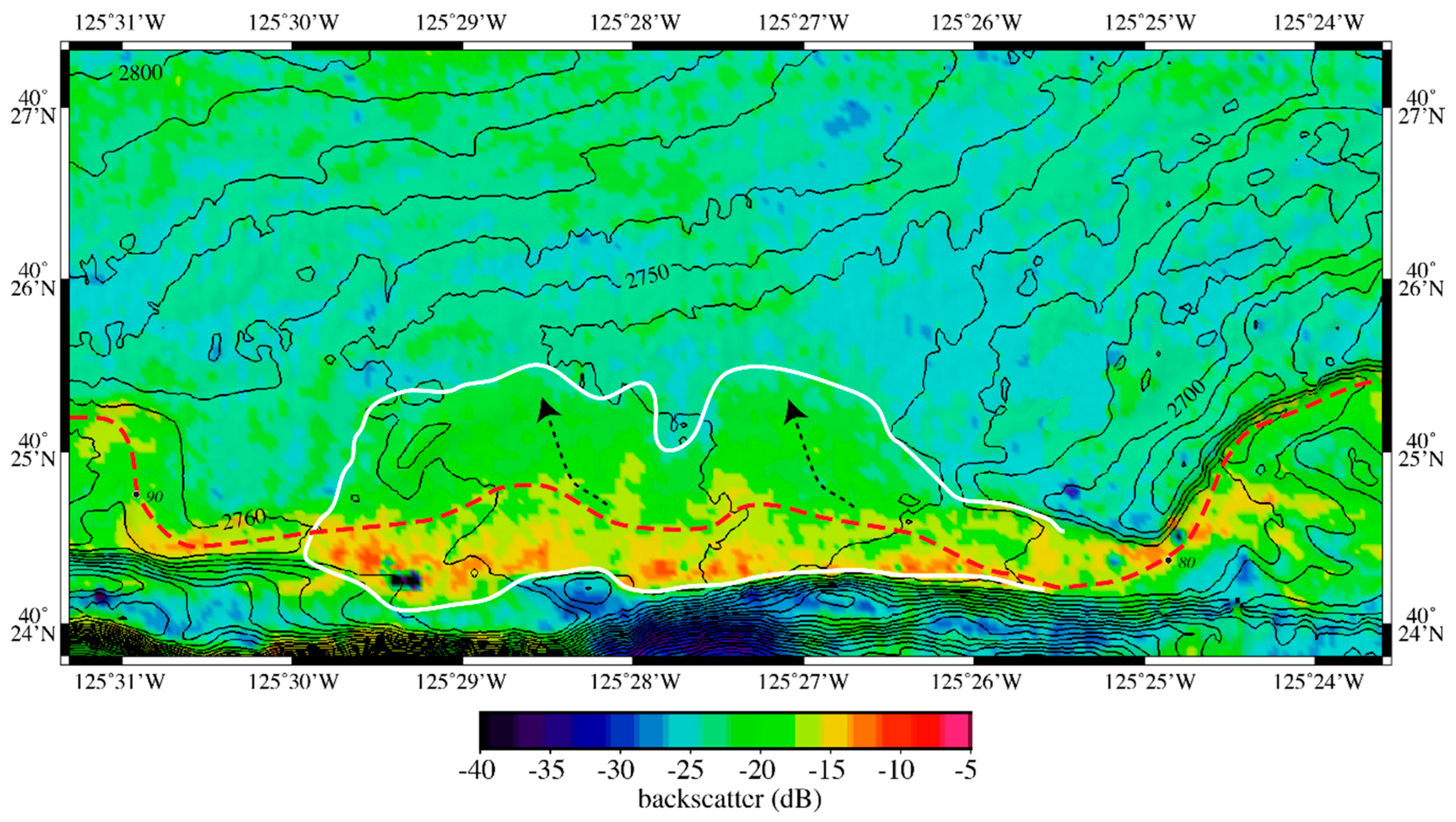
4.4. Mendocino Channel Crevasse Splay
4.5. Mendocino Channel Lower Sinuous Reach (Landslide and Beyond Landslide)
4.6. Mendocino Channel Lower Straight Reach (LSR)
5. Discussion
5.1. The Age of Mendocino Channel
5.2. Potential Processes
5.2.1. Seismicity
5.2.2. Wave-Loading Resuspension
5.2.3. Hyperpycnal Plumes
5.2.4. Eustatic Sea Levels
5.2.5. Tsunamis
6. Conclusions
7. Summary
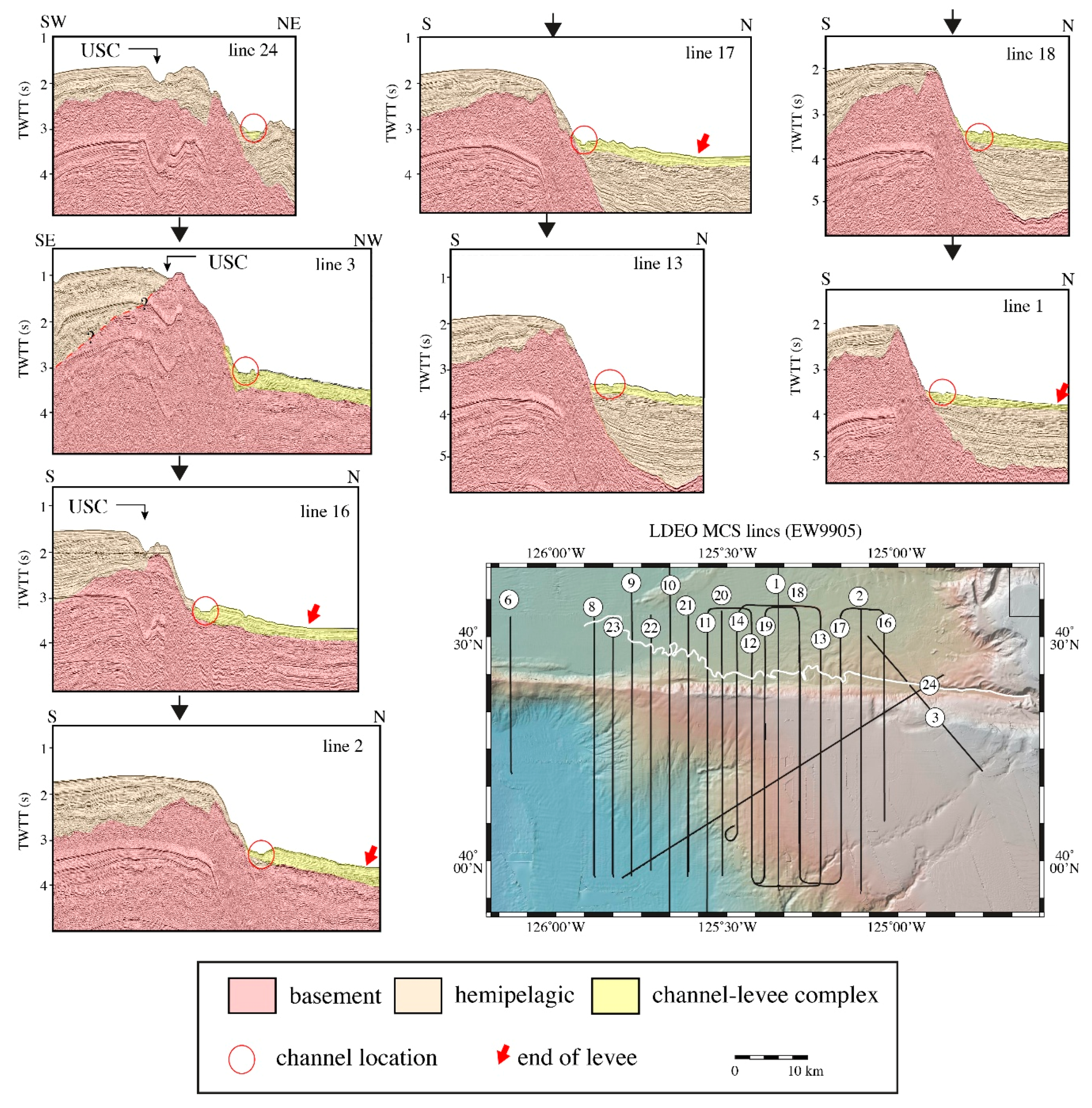
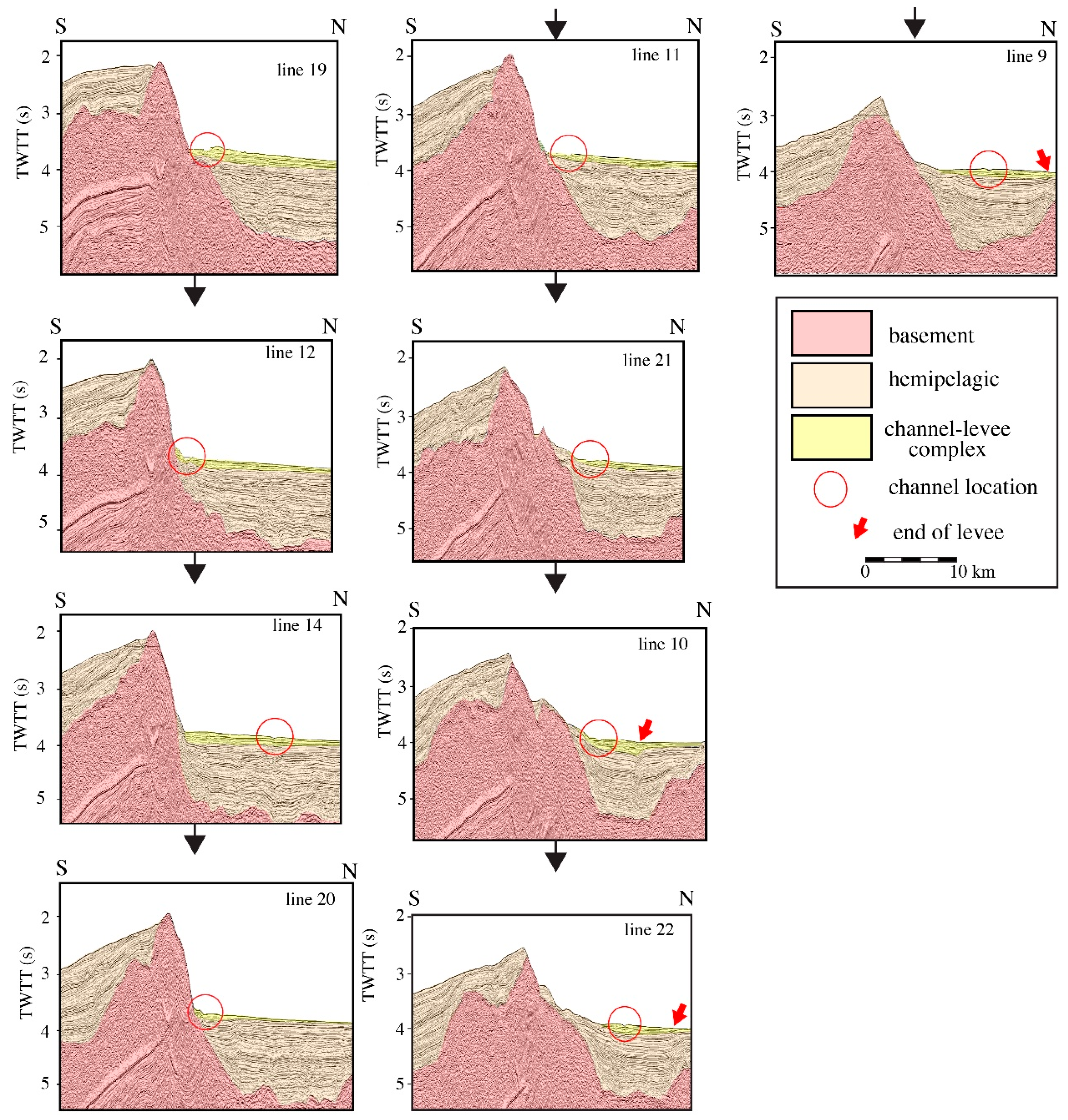
- Newly acquired multibeam bathymetry and backscatter data, together with published multichannel seismic and sediment core data provides a quantitative geomorphometric analysis of the entire extent of Mendocino Channel and to explore the age and possible causes that may have contributed to the formation and maintenance of the channel.
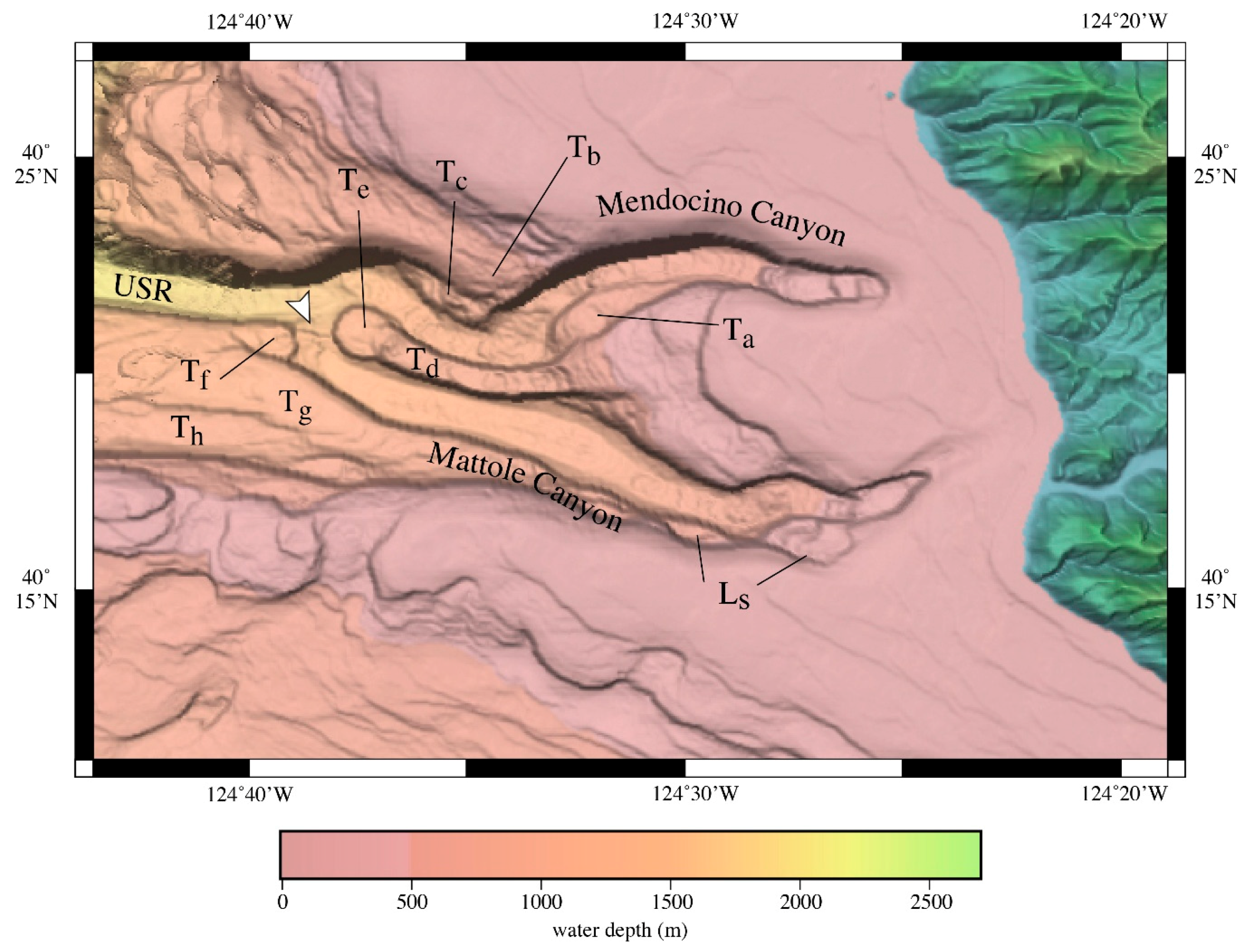
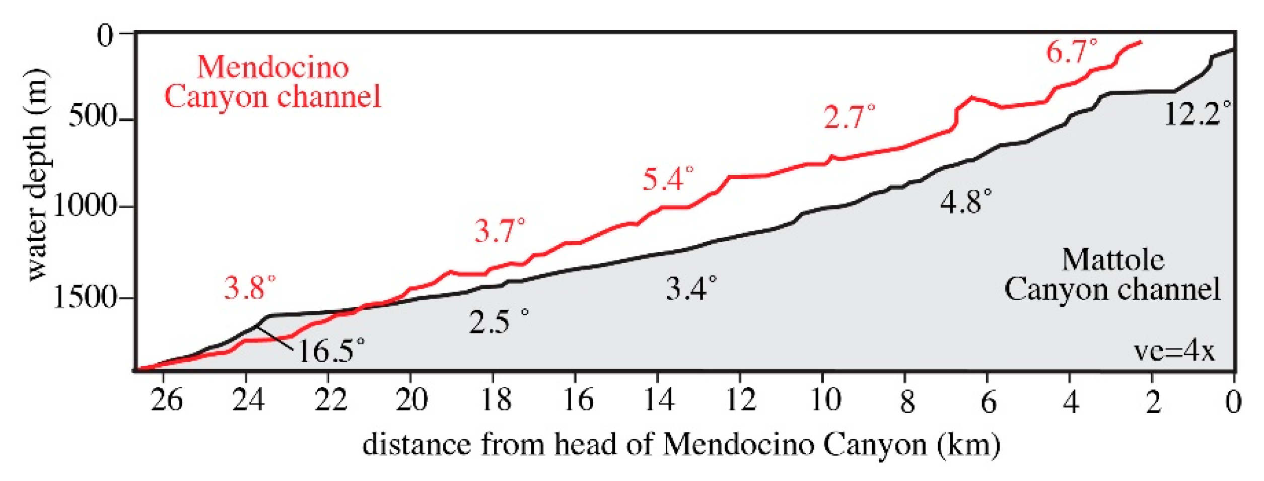
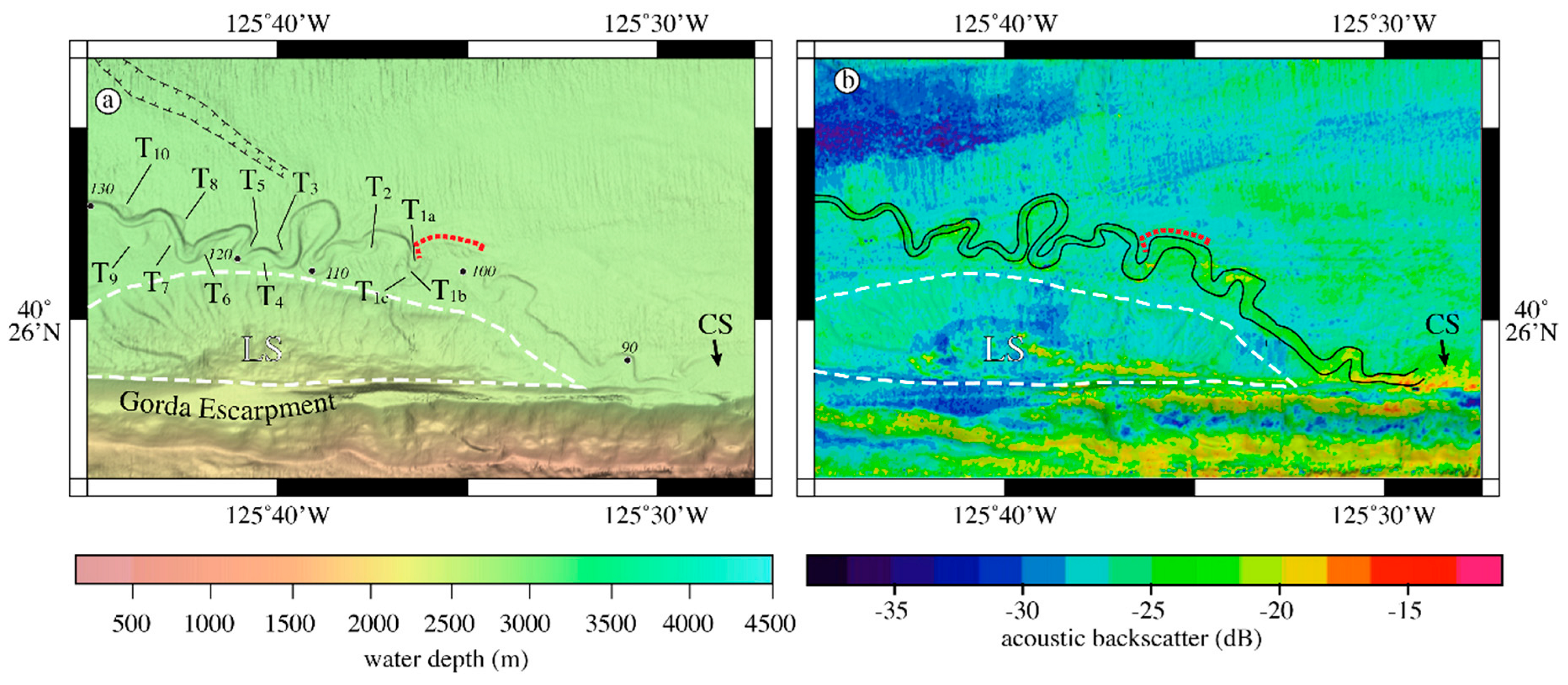
- Mendocino Channel has evolved from the confluence of Mendocino and Mattole Canyon channels at the point where Mattole Canyon channel was captured by Mendocino Canyon channel.
- The concave-up profile of Mattole Canyon channel suggests it is in the process of reaching, or has reached, an equilibrium profile whereas the concave-down profile of Mendocino Canyon channel suggests it is largely inactive.
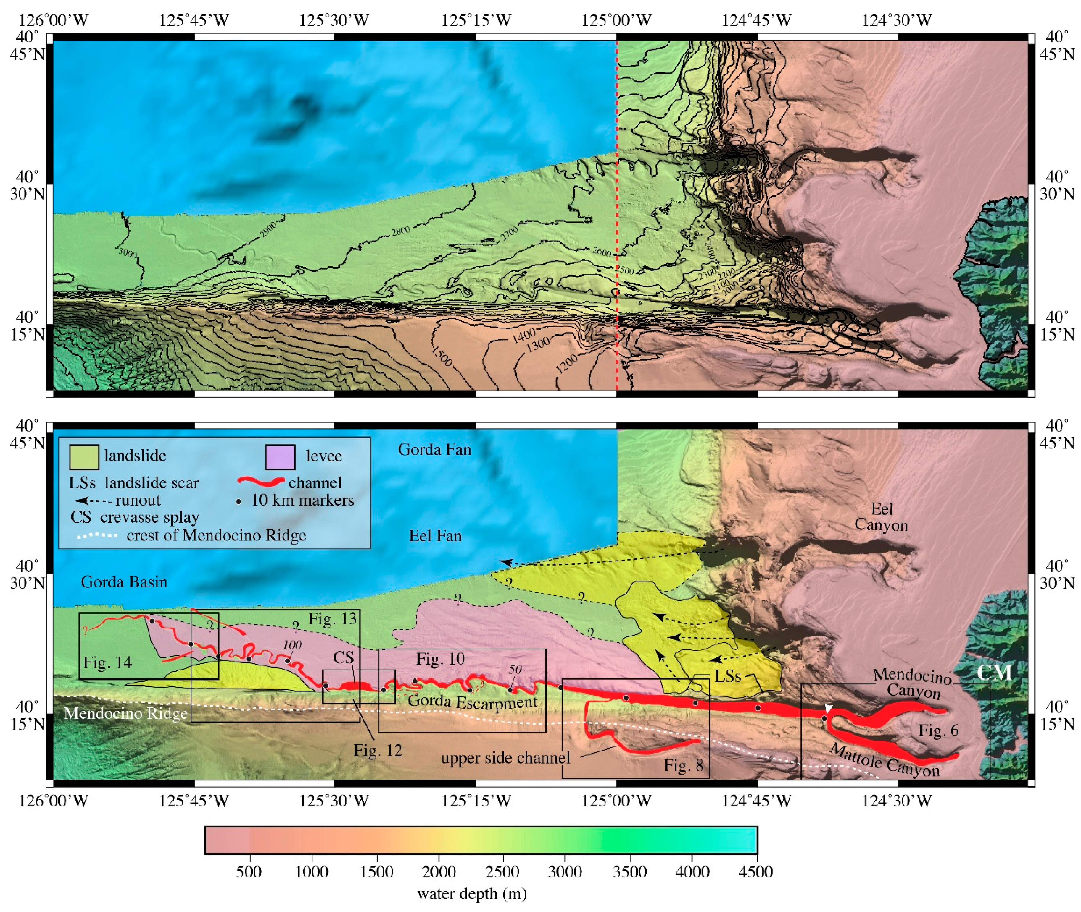
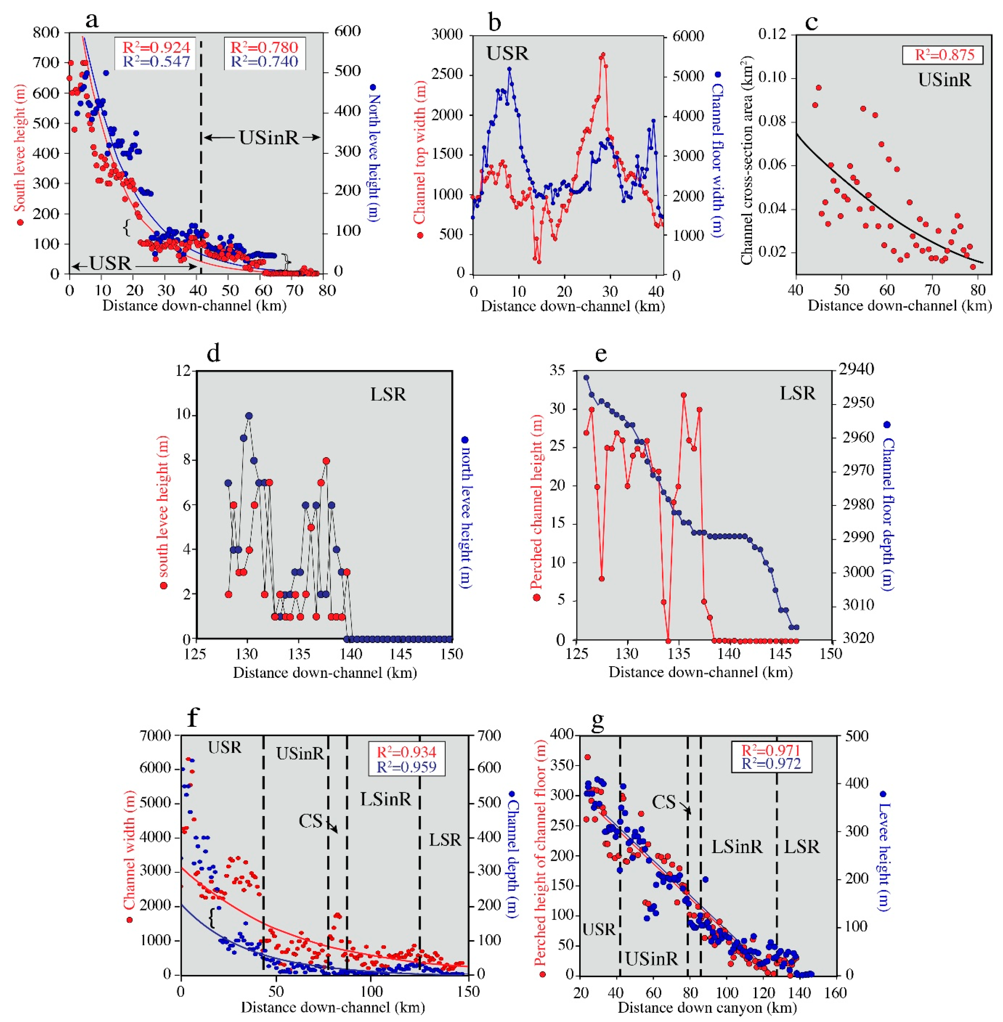
- The 148 km length of Mendocino Channel can be subdivided into sinuous and linear reaches based on planform geometry.
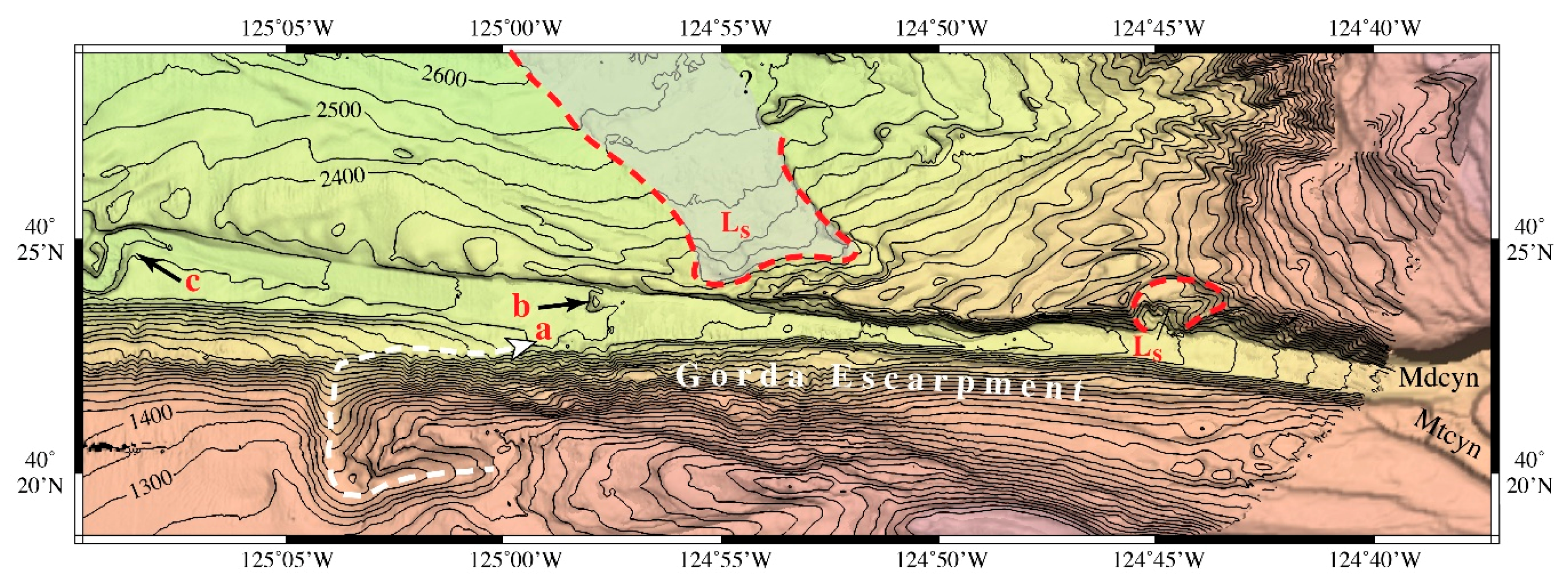
- Mendocino Channel trends westward along the base of Gorda Escarpment and descends 365 m along an inclined perch towards basin water depths until the channel is deflected to the northwest by a large landslide deposit.
- Changes from a linear reach to a sinuous reach and back to a linear reach are abrupt with 90° bends.
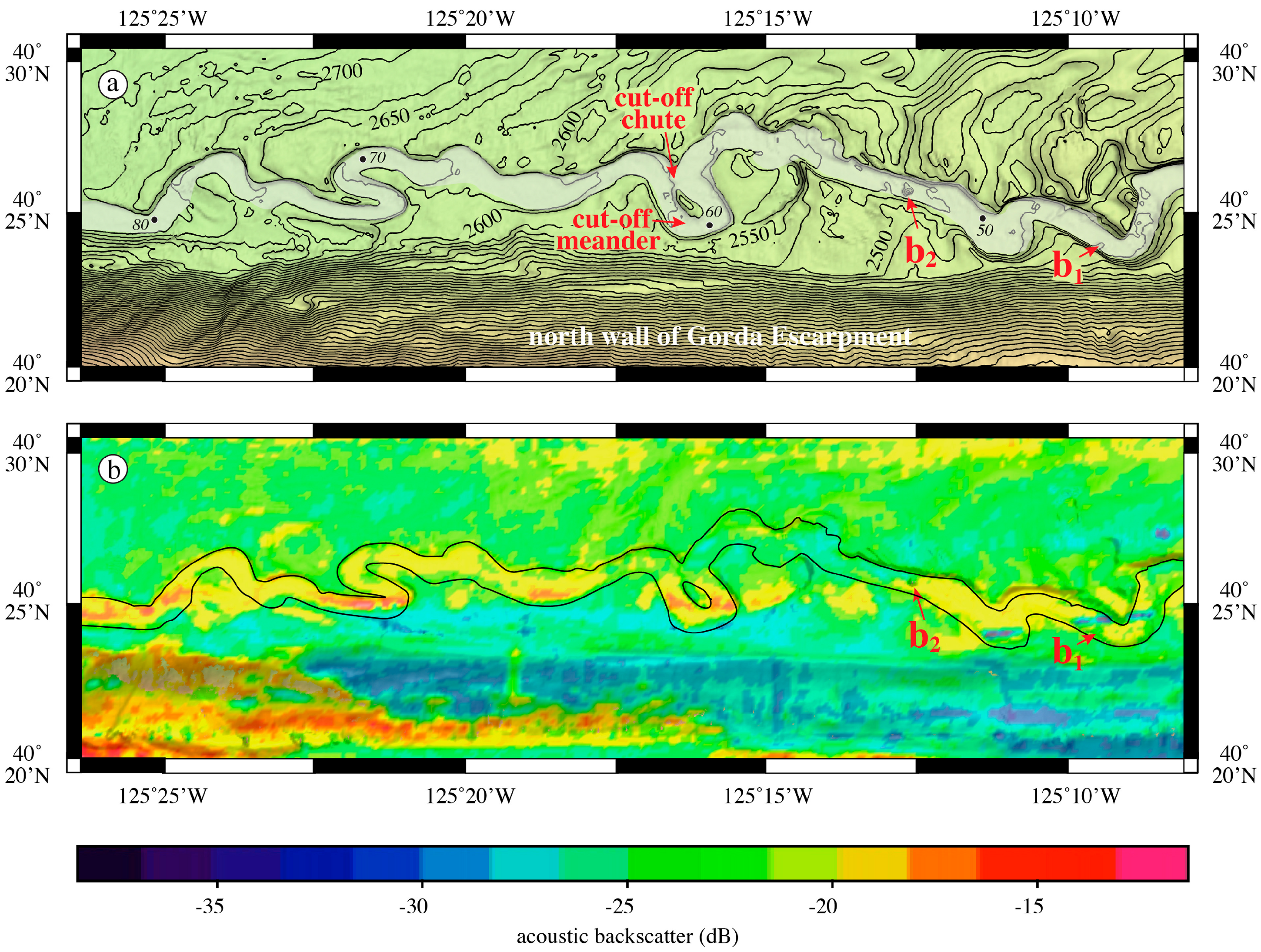
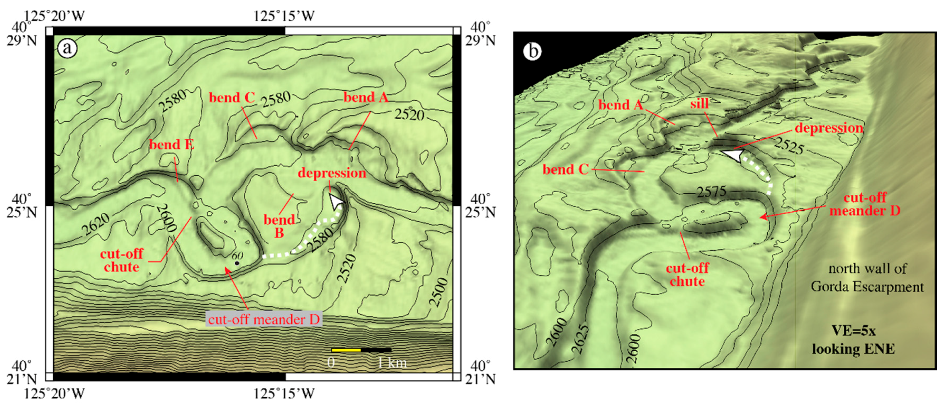
- There are several 180° meanders and 2 cut-off meanders in the sinuous reaches.
- Both inside-bend and outside-bend terraces are found on the sinuous reaches; some are paired terraces and some are unpaired.
- Although landslides are evident along the north wall of Gorda Escarpment, there is very little evidence of landslide debris within Mendocino Channel.
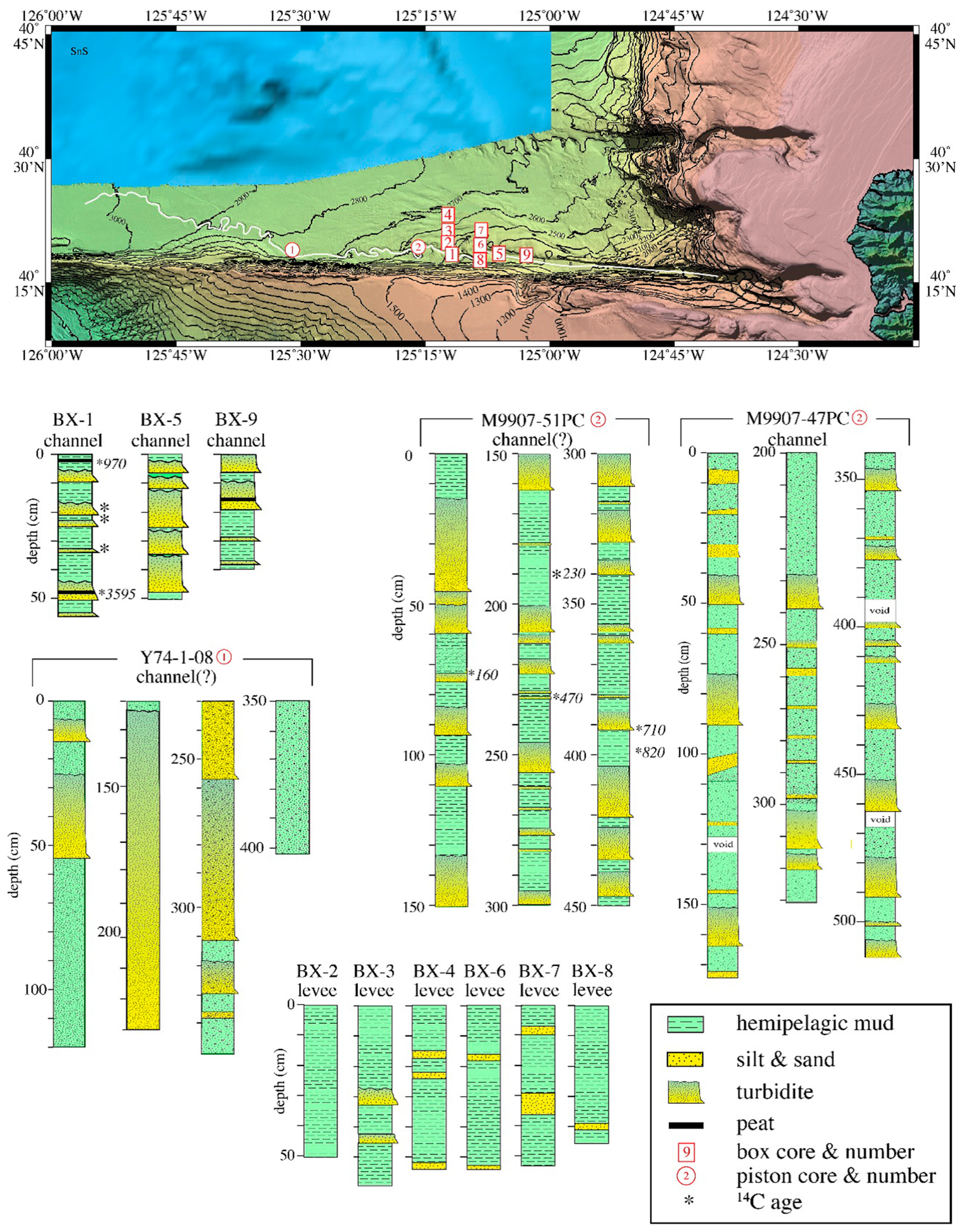
- Dated box and piston cores provide an estimate of the hemipelagic sedimentation rates that, when applied to the thickness of the channel-levee complex suggests the channel may be as old as 2.6–1.8 Ma (early Quaternary).
- A combination of significant and numerous earthquakes (seismicity) and wave-loading resuspension are the most likely processes that created the turbidity currents that have flowed down Mendocino Channel.
Acknowledgments
Conflicts of Interest
References
- Damuth, J.E.; Flood, R.D. Morphology, sedimentation processes, and growth pattern of the Amazon deep-sea fan. Geo-Marine Lett. 1983, 3, 109–117. [Google Scholar] [CrossRef]
- Flood, R.D.; Damuth, J.E. Quantitative characteristics of sinuous distributary channels on the Amazon deep-sea fan. Geol. Soc. Am. Bull. 1987, 98, 728–738. [Google Scholar] [CrossRef]
- Shanmugam, G.; Moiola, R.J. Submarine fans: Characteristics, models, classification, and reservoir potential. Earth Sci. Rev. 1988, 24, 383–428. [Google Scholar] [CrossRef]
- Wynn, R.B.; Cronin, B.T.; Peakall, J. Sinuous deep-water channels: Genesis, geometry and architecture. Mar. Pet. Geol. 2007, 24, 341–387. [Google Scholar] [CrossRef]
- Cacchione, D.A.; Drake, D.E.; Gardner, J.V. Recent meandering channel at the base of Mendocino Escarpment. In Geology of the U.S. Seafloor: The View from GLORIA; Gardner, J.V., Field, M.E., Twichell, D.C., Eds.; Cambridge University Press: Cambridge, UK, 1996; pp. 181–192. [Google Scholar]
- Gardner, J.V. Program EEZ-SCAN: A Reconnaissance View of the Western U.S. Exclusive Economic Zone. Available online: https://books.google.com.hk/books?id=-4vKMaCm2RUC&pg=PA125&lpg=PA125&dq=A+reconnaissance+view+of+the+western+U.S.+Exclusive+Economic+Zone&source=bl&ots=WjSK8mYdC1&sig=XZ7J2vHuNt7rLG1nlrsph_XPfWM&hl=en&sa=X&ved=0ahUKEwjf08CU6q3XAhVDT7wKHTMTBgQQ6AEIOjAH#v=onepage&q=A%20reconnaissance%20view%20of%20the%20western%20U.S.%20Exclusive%20Economic%20Zone&f=false (accessed on 9 September 2017).
- EEZ-SCAN 84 Scientific Staff. Atlas of the Exclusive Economic Zone, Western Conterminous United States: U.S. Geological Survey Miscellaneous Investigations Series I-l792; U.S. Geological Survey: Reston, VA, USA, 1986.
- Damuth, J.E.; Kolla, V.; Flood, R.D.; Kowsmann, R.O.; Monteiro, M.; Gorini, M.A.; Palma, J.J.; Belderson, R.H. Distributary channel meandering and bifurcation patterns on the Amazon deep-sea fan as revealed by long-range side-scan sonar (GLORIA). Geology 1983, 11, 94–98. [Google Scholar] [CrossRef]
- Primez, C.; Flood, R.D. Morphology and Structure of Amazon Channel. Available online: http://www-odp.tamu.edu/publications/155_IR/VOLUME/CHAPTERS/ir155_03.pdf (accessed on 9 September 2017).
- Curray, J.R.; Moore, D.G. Growth of the Bengal deep-sea fan and denudation in the Himalayas. Geol. Soc. Am. Bull. 1971, 82, 563–572. [Google Scholar] [CrossRef]
- Weber, M.E.; Wiedicke, M.H.; Kudrass, H.R.; Hübscher, C.; Erienkeuser, H. Active growth of the Bengal Fan during sea-level rise and highstand. Geology 1997, 25, 315–318. [Google Scholar] [CrossRef]
- Hubscher, C.; Spieβ, V.; Breitzke, M.; Weber, M.E. The youngest channel-levee system of the Bengal Fan: Results from digital sediment echosounder data. Mar. Geol. 1997, 141, 125–145. [Google Scholar] [CrossRef]
- Curray, J.R.; Emmel, F.J.; Moore, D.G. The Bengal Fan: Morphology, geometry, stratigraphy, history and processes. Mar. Pet. Geol. 2003, 19, 1191–1223. [Google Scholar] [CrossRef]
- Schwenk, T.; Spieβ, V.; Hübscher, C.; Breitzke, M. Frequent channel avulsions within the active channel-levee system of the middle Bengal Fan-an exceptional channel-levee development derived from Parasound and Hydrosweep data. Deep-Sea Res. II 2003, 50, 1023–1045. [Google Scholar] [CrossRef]
- Deptuck, M.E.; Steffens, G.S.; Barton, M.; Pirmez, C. Architecture and evolution of upper fan channel-belts on the Niger Delta slope and in the Arabian Sea. Mar. Pet. Geol. 2003, 20, 649–676. [Google Scholar] [CrossRef]
- Kastens, K.A.; Shor, A.N. Evolution of a channel meander on the Mississippi deep-sea fan. Mar. Geol. 1983, 71, 165–175. [Google Scholar] [CrossRef]
- Twichell, D.C.; Kenyon, N.H.; Parson, L.M.; McGregor, B.A. Depositional patterns of the Mississippi Fan surface: Evidence from GLORIA II and high-resolution seismic profiles. In Seismic Facies and Sedimentary Processes of Submarine Fans and Turbidite Systems; Weimer, P., Link, M.H., Eds.; Springer: New York, NY, USA, 1991; pp. 349–363. [Google Scholar]
- Droz, L.; Bellaiche, G. Rhone Deep-Sea Fan: Morphostructure and growth pattern. Am. Assoc. Pet. Geol. Bull. 1985, 69, 460–479. [Google Scholar]
- Droz, L.; Marsset, T.; Ondréas, H.; Lopez, M.; Savoye, B.; Spy-Anderson, F.-L. Architecture of an active mud-rich turbidite system: The Zaire Fan (Congo-Angola margin southeast Atlantic): Results from ZaïAngo 1 and 2 cruises. Am. Assoc. Pet. Geol. Bull. 2003, 87, 1145–1168. [Google Scholar] [CrossRef]
- Mulder, T.; Savoye, B.; Piper, D.J.W.; Syvitski, J.P.M. The Var submarine sedimentary system: Understanding Holocene sediment delivery processes and their importance to the geological record. In Geological Processes on Continental Margins: Sedimentation, Mass-Wasting and Stability; Stocker, M.S., Evans, D., Cramp, A., Eds.; Special Publication 129; Geological Society of London: London, UK, 1998; pp. 145–166. [Google Scholar]
- Lonsdale, P.; Hollister, C.D. Cut-offs at an abyssal meander south of Iceland. Geology 1979, 7, 597–601. [Google Scholar] [CrossRef]
- Lewis, K.B.; Pantin, H.M. Channel-axis, overbank and drift sediment waves in the southern Hikurangi Trough, New Zealand. Mar. Geol. 2002, 192, 123–151. [Google Scholar] [CrossRef]
- Gardner, J.V.; Malik, M.; Walker, S. Plume 1400 meters high discovered at the seafloor off the northern California margin. EOS 2009, 90, 275. [Google Scholar] [CrossRef]
- Peakall, J.; McCaffrey, B.; Kneller, B. A process model for the evolution, morphology; architecture of sinuous submarine channels. J. Sediment. Res. 2000, 70, 434–448. [Google Scholar] [CrossRef]
- Tréhu, A.M.; Stakes, D.S.; Bartlett, C.D.; Chevallier, J.; Duncan, R.A.; Goffredi, S.K.; Potter, S.M.; Salamy, K.A. Seismic and seafloor evidence for free gas, gas hydrates; fluid seeps n the transform margin offshore Cape Mendocino. J. Geophys. Res. 2003, 108. [Google Scholar] [CrossRef]
- Ware, C.; Knight, W.; Wells, D. Memory intensive statistical algorithms for multibeam bathymetric data. Comput. Geosci. 1991, 17, 985–993. [Google Scholar] [CrossRef]
- Schumm, S.A.; Brakenridge, G.R. River responses. In The Geology of North America, North America and Adjacent Oceans during the Last Deglaciation; Ruddiman, W.F., Wright, H.E., Jr., Eds.; v. K-3; The Geological Society of America: Boulder, CO, USA, 1987; pp. 221–240. [Google Scholar]
- Shepard, F.P.; Dill, R.F. Submarine Canyons and Other Sea Valleys; Rand McNally & Company: Chicago, IL, USA, 1966. [Google Scholar]
- Nakajima, T.; Peakall, J.; McCaffrey, W.D.; Paton, D.A.; Thompson, P.J.P. Outer-bank bars: A new intra-channel architectural element within sinuous submarine slope channels. J. Sediment. Res. 2009, 79, 872–886. [Google Scholar] [CrossRef]
- Goldfinger, C.; Nelson, C.H.; Morey, A.E.; Johnson, J.E.; Patton, J.R.; Karabanov, E.; Gutiérrez-Pastor, J.; Eriksson, A.T.; Gàrcia, E.; Dunhill, G.; et al. Turbidite Event History–Methods and Implications for Holocene Paleoseismicity of the Cascadia Subduction Zone. Available online: http://www.wou.edu/las/physci/taylor/g473/Goldfinger_etal_2011_excerpt_reading.pdf (accessed on 9 September 2017).
- Lyle, M.; Koizumi, I.; Richter, C. Proceedings of the Ocean Drilling Program, Initial Reports; Site 1020; U.S. Government Printing Office: Washington, DC, USA, 1997.
- Manley, P.I.; Flood, R.D. Cyclic sediment deposition within Amazon deep-sea fan. Am. Assoc. Pet. Geol. Bull. 1988, 72, 912–925. [Google Scholar]
- Flood, R.D.; Manley, P.L.; Kowsmann, R.O.; Appi, C.J.; Pirmez, C. Seismic facies and late Quaternary growth of Amazon submarine fan. In Seismic Facies and Sedimentary Processes of Submarine Fans and Turbidite Systems; Weimer, P., Link, M.H., Eds.; Springer: New York, NY, USA, 1991; pp. 415–433. [Google Scholar]
- Carlson, R.L.; Gangi, A.F.; Snow, K.R. Empirical reflection-traveltime/depth and velocity/depth functions for the deep-sea sediment column. J. Geophys. Res. 1986, 91, 8249–8266. [Google Scholar] [CrossRef]
- Gorsline, D.S.; De Diego, T.; Nava-Sanchez, E.H. Seismically triggered turbidites in small margin basins: Alfonso Basin, western Gulf of California and Santa Monica Basin, California Borderland. Sediment. Geol. 2000, 135, 21–35. [Google Scholar] [CrossRef]
- Babonneau, N.; Cattaneo, A.; Ratzov, G.; Déverchère, J.; Yelles-Chaouche, A.; Lateb, T.; Bachir, R. Turbidite chronostratigraphy off Algiers, central Algerian margin: A key for reconstructing Holocene paleo-earthquake cycles. Mar. Geol. 2017, 384, 63–80. [Google Scholar] [CrossRef]
- Pope, E.L.; Talling, P.J.; Carter, L. Which earthquakes trigger damaging submarine mass movements: Insights from a global record of submarine cable breaks? Mar. Geol. 2017, 384, 131–146. [Google Scholar] [CrossRef]
- Adams, J. Paleoseismicity of the Cascadia subduction zone–Evidence from turbidites off the Oregon-Washington margin. Tectonics 1990, 9, 569–583. [Google Scholar] [CrossRef]
- Clarke, S.H., Jr.; Carver, G.A. Late Holocene tectonics and paleoseismicity, southern Cascadia subduction zone. Science 1992, 255, 188–192. [Google Scholar] [CrossRef] [PubMed]
- Smith, S.; Knapp, J.S.; McPherson, R.C. Seismicity of the Gorda plate, structure of the continental margin, and an eastward jump of the Mendocino triple junction. J. Geophys. Res. 1993, 98, 8153–8171. [Google Scholar] [CrossRef]
- Covault, J.A.; Graham, S.A. Submarine fans at all sea-level stands: Tectono-morphologic and climatic controls on terrigenous sediment delivery to the deep sea. Geology 2010, 38, 939–942. [Google Scholar] [CrossRef]
- Puig, P.; Ogston, A.S.; Mullenbach, B.L.; Nittrouer, C.A. Shelf-to-canyon sediment-transport processes on the Eel continental margin (northern California). Mar. Geol. 2003, 193, 129–149. [Google Scholar] [CrossRef]
- Parsons, J.D.; Friedrichs, C.T.; Traykovski, P.A.; Mohrig, D.; Imran, J.; Syvitski, J.P.M.; Parker, G.; Puig, P.; Buttles, J.L.; Garcia, M.H. The mechanics of marine sediment gravity flows. In Continental Margin Sedimentation: From Sediment Transport to Sequence Stratigraphy; Nittrouer, C.A., Austin, J.A., Field, M.E., Kravity, J.H., Syvitski, J.P.M., Wiberg, P.L., Eds.; International Association of Sedimentologists Special Publication 37; Wiley-Blackwell: Hoboken, NJ, USA, 2007; pp. 275–337. [Google Scholar]
- Nittrouer, C.A.; Austin, J.A.; Field, M.E.; Kravitz, J.H.; Syvitski, J.P.M.; Wiberg, P.L. Continental Margin Sedimentation: From Sediment Transport to Sequence Stratigraphy; International Association of Sedimentologists Special Publication 37; John Wiley & Sons, Inc.: Hoboken, NJ, USA, 2007. [Google Scholar]
- Jin, F.-F.; Bourharel, J.; Lin, I.-I. Eastern Pacific tropical yclones intensified by El Nino delivery of subsurface ocean heat. Nature 2014, 516, 82–84. [Google Scholar] [CrossRef] [PubMed]
- Cane, M.A. The evolution of El Niño, past and future. Earth Planet. Sci. Lett. 2005, 230, 227–240. [Google Scholar] [CrossRef]
- Felix, M.; Peakall, J.; McCaffrey, W.D. Relative importance of processes that govern the generation of particulate hyperpycnal flows. J. Sediment. Res. 2006, 76, 382–387. [Google Scholar] [CrossRef]
- Mulder, T.; Syvitski, J.P.M. Turbidity currents generated at river mouths during exceptional discharges to the world oceans. J. Geol. 1995, 103, 285–299. [Google Scholar] [CrossRef]
- Imran, J.; Syvitski, J.P.M. Impact of extreme river events on the coastal ocean. Oceanography 2000, 13, 85–92. [Google Scholar] [CrossRef]
- Mulder, T.; Syvitski, J.P.M.; Migeon, S.; Faugères, J.-C.; Savoye, B. Marine hyperpycnal flows: Initiation, behavior and related deposits: A review. Mar. Pet. Geol. 2003, 20, 861–882. [Google Scholar] [CrossRef]
- Dadson, S.J.; Hovius, N.; Chen, H.; Date, W.B.; Lin, J.-C.; Hsu, M.-L.; Lin, C.-W.; Horng, M.J.; Chen, T.-C.; Milliman, J.; et al. Earthquake-triggered increase in sediment delivery from an active mountain belt. Geology 2004, 32, 733–736. [Google Scholar] [CrossRef]
- Nittrouer, C.A.; Austin, J.A.; Field, M.E.; Kravitz, J.H.; Syvitski, J.P.M.; Wiberg, P.L. Writing a Rosetta stone: Insights into continental-margin sedimentary processes and strata. In Continental Margin Sedimentation: From Sediment Transport to Sequence Stratigraphy; International Association of Sedimentologists Special Publication 37; Wiley-Blackwell: Hoboken, NJ, USA, 2007. [Google Scholar]
- Wynn, R.B.; Weaver, P.P.E.; Ercilla, G.; Stow, D.A.V.; Masson, D.G. Sedimentary processes in the Selvage sediment-wave field, NE Atlantic: New insights into the formation of sediment waves by turbidity currents. Sedimentology 2007, 47, 1181–1197. [Google Scholar] [CrossRef]
- Piper, D.J.W.; Savoye, B. Processes of late Quaternary turbidity current flow and deposition of the Var deep-sea fan, north-west Mediterranean Sea. Sedimentology 1993, 40, 557–582. [Google Scholar] [CrossRef]
- Kao, S.J.; Dai, M.; Selvaraj, K.; Zhai, W.; Cai, P.; Dhen, S.N.; Yang, J.Y.T.; Liu, J.T.; Liu, C.C.; Syvitski, J.P.M. Cyclone-driven deep sea injection of freshwater and heat by hyperpycnal flow in the subtropics. Geophys. Res. Lett. 2010, 37, 1–5. [Google Scholar] [CrossRef]
- Gavey, R.; Carter, L.; Liu, J.T.; Talling, P.J.; Hsu, R.; Pope, E.; Evans, G. Frequent sediment density flows during 2006 to 20154, triggered by competing seismic and weather events: Observations from subsea cable breaks off southern Taiwan. Mar. Geol. 2017, 384, 147–158. [Google Scholar] [CrossRef]
- Lee, H.J.; Locat, J.; Desgagnés, P.; Parsons, J.D.; McAdoo, B.G.; Orange, D.L.; Puig, P.; Wong, F.L.; Dartnell, P.; Boulanger, E. Submarine mass movements on continental margins. In Continental Margin Sedimentation: From Sediment Transport to Sequence Stratigraphy; Nittrouer, C.A., Austin, J.A., Field, M.E., Kravitz, J.H., Syvitski, J.P.M., Wiberg, P.L., Eds.; International Association of Sedimentologists Special Publication 37; Wiley-Blackwell: Hoboken, NJ, USA, 2007; pp. 213–274. [Google Scholar]
- Sumner, E.J.; Paull, C.K. Swept away by a turbidity current in Mendocino submarine canyon, California. Geophys. Res. Lett. 2014, 41, 7611–7618. [Google Scholar] [CrossRef]
- Shackleton, N.J. Oxygen isotopes, ice volume and sea level. Quat. Sci. Rev. 1987, 6, 183–190. [Google Scholar] [CrossRef]
- De Boer, B.; van de Wal, R.S.W.; Bintanja, R.; Lourens, L.J.; Tuenter, E. Cenozoic global ice-volume and temperature simulations with 1-D ice-sheet models forced by benthic δ18O records. Ann. Glaciol. 2010, 51, 23–33. [Google Scholar] [CrossRef]
- Shanmugam, G. The tsunamite problem. J. Sediment. Res. 2006, 76, 718–730. [Google Scholar] [CrossRef]
- Bourgeois, J. Geologic effects and records of tsunamis. In The Sea; Robinson, A.R., Bernard, E.N., Eds.; v. 15: Tsunamis; Harvard University Press: Cambridge, MA, USA, 2009; pp. 53–91. [Google Scholar]
- Paris, R.; Fournier, J.; Poizot, E.; Etienne, S.; Morin, J.; Lavigne, F.; Wassmer, P. Boulder and fine sediment transport and deposition by the 2004 tsunami in Lhok Nga (western Banda Aceh, Sumatra, Indonesia): A coupled offshore-onshore model. Mar. Geol. 2010, 268, 43–54. [Google Scholar] [CrossRef]
- Yamazaki, Y.; Cheung, K.F. Shelf resonance and impact of near-field tsunami generated by the 2010 Chile earthquake. Geophys. Res. Lett. 2011, 38. [Google Scholar] [CrossRef]
- Sakuna, C.; Szczuciński, W.; Feldens, P.; Schwarzer, K.; Khokiattiwong, S. Sedimentary deposits left by the 2004 Indian Ocean tsunami on the inner continental shelf offshore of Khao Lak, Andaman Sea (Thailand). Earth Planets Space 2012, 64, 931–943. [Google Scholar] [CrossRef]
- Atwater, B.F.; Hemphill-Haley, E. Recurrence Intervals for Great Earthquakes of the Past 3500 Years at Northeastern Willapa Bay; U.S. Government Printing Office: Washington, DC, USA, 1997; p. 108.
- Hemphill-Haley, E. Diatom evidence for earthquake-induced subsidence and tsunami 300 yr ago in southern coastal Washington. Geol. Soc. Am. Bull. 1995, 107, 367–378. [Google Scholar] [CrossRef]
- Garrison-Laney, C.E.; Abramson-Ward, H.F.; Carver, G.A. Late Holocene tsunamis near the southern end of the Cascadia subduction zone. Seismol. Res. Lett. 2002, 73, 248. [Google Scholar]
- Weiss, R. Sediment grains moved by passing tsunami waves: Tsunami deposits in deep water. Mar. Geol. 2008, 50, 251–257. [Google Scholar] [CrossRef]
- Schumm, S.A. Patterns of alluvial rivers. Annu. Rev. Earth Planet. Sci. 1985, 13, 5–27. [Google Scholar] [CrossRef]


| Terrace Number | Terrace Water Depth (m) | Height above Channel (m) | Terrace Orientation |
|---|---|---|---|
| T1 | 2846 | 4 | flat |
| T2 | 2857 | 8 | tilt towards channel 1.2° |
| T3 | 2891 | 15 | tilt towards channel 1.6° |
| T4 | 2887 | 20 | tilt towards channel 1.4° |
| T5 | 2897 | 15 | tilt towards channel 1.5° |
| T6 | 2909 | 21 | tilt towards channel 3.2° |
| T7 | 2912 | 27 | tilt towards channel 1.5° |
| T8 | 2914 | 27 | flat |
| T9 | 2924 | 24 | flat |
| T10 | 2923 | 25 | flat |
© 2017 by the author. Licensee MDPI, Basel, Switzerland. This article is an open access article distributed under the terms and conditions of the Creative Commons Attribution (CC BY) license (http://creativecommons.org/licenses/by/4.0/).
Share and Cite
Gardner, J.V. The Morphometry of the Deep-Water Sinuous Mendocino Channel and the Immediate Environs, Northeastern Pacific Ocean. Geosciences 2017, 7, 124. https://doi.org/10.3390/geosciences7040124
Gardner JV. The Morphometry of the Deep-Water Sinuous Mendocino Channel and the Immediate Environs, Northeastern Pacific Ocean. Geosciences. 2017; 7(4):124. https://doi.org/10.3390/geosciences7040124
Chicago/Turabian StyleGardner, James V. 2017. "The Morphometry of the Deep-Water Sinuous Mendocino Channel and the Immediate Environs, Northeastern Pacific Ocean" Geosciences 7, no. 4: 124. https://doi.org/10.3390/geosciences7040124
APA StyleGardner, J. V. (2017). The Morphometry of the Deep-Water Sinuous Mendocino Channel and the Immediate Environs, Northeastern Pacific Ocean. Geosciences, 7(4), 124. https://doi.org/10.3390/geosciences7040124