Article

Fifteen Years of Radionuclide Research at the KIT Synchrotron Source in the Context of the Nuclear Waste Disposal Safety Case

1
Karlsruhe Institute of Technology (KIT), Institute for Nuclear Waste Disposal (INE), P.O. Box 3640, D-76021 Karlsruhe, Germany
2
Helmholtz-Zentrum Dresden-Rossendorf (HZDR), Institute of Resource Ecology (IRE), Bautzner Landstrasse 400, D-01328 Dresden, Germany
3
Rossendorf Beamline at ESRF—The European Synchrotron, CS40220, F-38043 Grenoble CEDEX 9, France
*
Author to whom correspondence should be addressed.
Geosciences 2019, 9(2), 91; https://doi.org/10.3390/geosciences9020091
Submission received: 16 December 2018 / Revised: 28 January 2019 / Accepted: 29 January 2019 / Published: 15 February 2019

Abstract

:
For more than 120 years, systematic studies of X-ray interaction with matter have been the basis for our understanding of materials—both of natural or man-made origin—and their structure-function relationships. Beginning with simple radiographic imaging at the end of the 19th century, X-ray based analytical tools such as X-ray diffraction, X-ray fluorescence and photoemission or X-ray absorption techniques are indispensable in almost any field of chemical and material sciences—including basic and applied actinide and radionuclide studies. The advent of dedicated synchrotron radiation (SR) sources in the second half of the last century has revolutionized the analytical power of X-ray probes, while—with increasing number of SR facilities—beamline instrumentation followed a trend towards increasing specialization and adaption to a major research topic. The INE-Beamline and ACT station at the KIT synchrotron source belong to the exclusive club of a few synchrotron beamline facilities—mostly located in Europe—dedicated to the investigation of highly radioactive materials. Since commissioning of the INE-Beamline in 2005, capabilities for synchrotron-based radionuclide and actinide sciences at KIT have been continuously expanded, driven by in-house research programs and external user needs.

1. Introduction

Synchrotron radiation (SR) based speciation techniques have become key methods in basic and applied radionuclide research. In the context of Germany’s nuclear energy phase-out and “energy transition” to renewable resources, this development is primarily driven by the need to secure molecular-scale understanding of (geo-)chemical processes determining the mobility of safety relevant radionuclides (i.e., long-lived actinides, fission and activation products generated during nuclear reactor operation for more than five decades), possibly released from a projected disposal system for highly active, heat-producing nuclear waste. Presently, final disposal in deep bedrock repositories is deemed as the preferred option worldwide for the management of spent nuclear fuel (SNF) and high-level waste (HLW) glass used for conditioning of highly radioactive residues from nuclear fuel reprocessing. This disposal concept generally relies on the isolating effect of multiple barriers (i.e., the actual waste form, the technical barriers (steel canister, backfill material inside emplacement chambers, etc.) and the host rock formation with its overburden) to prevent water access to the encapsulated waste matrices or—in case of canister breaching scenarios, where waste degradation following water intrusion might result in the release of radionuclides – promote efficient retention reactions in the repository near-field. Solving the nuclear disposal safety case requires the assessment of mobilization and retention processes on geological time scales in order to derive a reliable source term, i.e., the amount of radiotoxic isotopes which might—assuming the worst case—find a pathway back to the biosphere. Speciation techniques like XAS (X-ray Absorption Spectroscopy) provide necessary input parameters (i.e., the physicochemical state of radionuclides under given chemical and thermodynamic boundary conditions such as, e.g., Eh, pH, ionic strength, presence of complexation agents or adsorbing surfaces etc.) to model long-term evolution scenarios of a projected underground repository for nuclear waste. All countries currently utilizing nuclear fission as energy source—regardless of their concepts for a sustainable future energy mix—are facing additional challenges imposed by the foreseeable prolongation of SNF and HLW-glass interim storage until the availability of a societally acceptable, fully licensed and technically functional final repository. Thus, in addition, attempts to directly characterize SNF and HLW-glass matrices by XAFS (X-ray Absorption Fine Structure, i.e., EXAFS and NEXAFS/XANES), which is gaining focus in order to address the present speciation of the radionuclide inventory as well as the possible impact of prolonged dry storage on SNF integrity and future transportability of SNF rods [1,2]
The “INE-Beamline” for radionuclide science at the KIT synchrotron source was conceived in 2004 as a flexible experimental station for X-ray based radionuclide speciation investigations. About one decade later, commissioning of the new hard X-ray beamline “CAT-ACT” for CATalysis and ACTinide research at an adjacent beam port has been completed [3] and the ACT laboratory for synchrotron-based radionuclide speciation studies is now fully licensed. Both stations allow to handle radioisotopes with activities up to one million times their (isotope specific) European exemption limits. To our knowledge, the INE-Beamline and the ACT experimental station are the only facilities of their kind in the world offering direct access to radiochemistry laboratories operating a shielded box-line in close proximity to the synchrotron light source on the same research campus. Sample transfers are fast and are generally organized with a minimum of administrative effort.
After conversion of the former KIT light source ANKA from a national user facility to a KIT internal research infrastructure (now the KArlsruhe Research Accelerator KARA, cf. [4]) in 2015, INE and ACT beamline operation had to be adapted to suit dual use as a SR source and accelerator technology test facility with R&D projects in the fields of superconducting insertion devices, novel electron fill patterns and operation modes (e.g., for generation of coherent THz radiation), and beam diagnostic tools. As a direct consequence, SR beamtime distribution is no longer based on a competitive peer review proposal process, but on in-house needs within the KIT and HGF (Helmholtz Association of German Research Centres) programs and on individual agreements between KIT and external cooperation partners.
This contribution to the Geosciences’ special issue on “The Development and Use of Synchrotron Radiation Techniques for the Geological Disposal of Radioactive Wastes” summarizes the past 15 years of XAFS-based radionuclide research at KIT from the authors’ perspective and highlights some examples for recent or ongoing research at the INE-Beamline and ACT stations at the local synchrotron source. It is neither meant to be a general review in the field, nor does it claim that such work can be exclusively accomplished at dedicated radionuclide beamline end-stations (e.g., the extensive radionuclide research conducted at SSRL/National Accelerator Laboratory, ALS / Lawrence Berkeley National Laboratory and APS/Argonne National Laboratory in the United States or at SPring-8, Japan). For an excellent overview on XAFS applications in the nuclear fuel cycle context, the reader is referred to a comprehensive article by M.A. Denecke in the recent XAS compendium by van Bokhoven and Lamberti [5].

2. Performing Experiments with Radionuclides at the KIT Synchrotron Source

Both the experimental hutch at the INE-Beamline (bending magnet source, Ec = 6 keV, cf. [6] for technical details) and the ACT laboratory (sharing the same superconducting wiggler source (Ec = 10.2 keV) and optics with the in-line CAT laboratory, cf. [7] for technical details) are equipped and licensed to perform SR-based experiments with radionuclides up to 1 × 10⁶ times the specific European exemption limits of non-fissile isotopes and 200 mg each of fissile 235U and 239Pu. Therefore, both stations are operated as temporary controlled area laboratories with restricted access. From the beginning of the design phase of both stations, emphasis was placed on allowing for highest flexibility and variability in experimental design, sample geometry, and conditions during measurements—at the same time ensuring that all legal requirements and safety precautions are always enforced. There are basically only two rules to be adhered to: the maximum allowed activity inside the experimental hutches (in the case where several radioisotopes are present at the same time, a simple sum rule applies just by keeping the summed percentages from the upper limit taken by each isotope below 100%) and all samples, regardless of their physical or chemical state, have to be kept enclosed by two independent layers of sealed containment during all phases of the experiment. Measurements of highly radioactive materials within the aforementioned activity license (e.g., fragments of highly active waste, cf. Section 4.2) are deemed safe, if they can be safely extracted from the INE shielded box-line and loaded in sealed beamline sample holders at INE-controlled area labs, irrespective of their actual contact dose rate. In case of non-standard experiments as for routine XAFS data acquisition in transmission or X-ray fluorescence emission mode (e.g., in-situ experiments at non-ambient conditions), a technical commission formed by KIT-INE radiation safety experts evaluates the proposed experiment and issues guidelines if relevant procedures have to be improved. The reader is referred to refs. [6,7] for an in-depth description of INE and ACT beamline infrastructure, sample transfer, and handling protocols as well as access routes for non-KIT user groups.

3. Highlights of Past Research Projects

Besides serving KIT and HGF in house research projects, the experimental capabilities at the INE-Beamline and ACT station have been shared from the beginning with external user groups, notably via the meanwhile terminated ANKA peer review based user operation as an access route. Since INE-Beamline commissioning in 2005, special emphasis has been placed on aspects of training and education, enabling the next generation of young European scientists to contribute to future safe radionuclide management in various aspects of the nuclear fuel cycle. In this context, the INE-Beamline and the INE controlled area labs have been designated as “pooled facilities” in the EURATOM seventh framework Integrated Infrastructure Initiative ACTINET-I3 (10/2009–01/2013) and its follow-up project TALISMAN (Transnational Access to Large Infrastructure for a Safe Management of ActiNides, 01/2013–2/2015 [8]). Operation of the INE-Beamline and ACT has resulted in more than 150 peer reviewed publications since 2005, mostly covering nuclear waste disposal safety aspects—notably those related to the field of actinide/radionuclide solubility and chemical thermodynamics, an area of markedly high expertise at KIT-INE—but also focusing on aspects dealt with by KIT-external groups such as transmutation target synthesis or basic actinide chemistry. Some highlights from the past decade are briefly summarized in this section.
Radionuclide work at the KIT synchrotron source profits from the unique possibility to perform in-situ XAS experiments on radioactive samples at non-ambient conditions. Whereas in-situ capabilities at beamlines dedicated to radionuclide research have been mostly limited to variations of the electrochemical potential to manipulate actinide oxidation states in aqueous medium (e.g., [9,10]), high temperature measurements on actinides have been only recently envisaged.
Near-field temperatures in a repository for SNF and HLW-glass are expected to reach up to 200 °C for disposal in rock salt formations, whereas maximum temperatures around 100 °C are expected to be reached in repositories in argillaceous host rocks and repositories with bentonite backfilling. In the former case, chloride will be the most abundant ligand available for complexation reactions with dissolved radionuclides upon (ground-)water influx. The chemical properties of radionuclides and potential ligands can change significantly at elevated temperatures. However, dedicated studies focusing on the impact of temperature on actinide solubility and speciation are generally scarce. Complexation of trivalent actinides is studied at KIT-INE in a systematic effort to reduce the knowledge gap on high-temperature aquatic actinide chemistry. Time Resolved Laser Fluorescence Spectroscopy (TRLFS) and XAFS have been combined to derive in-situ speciation information up to T = 200 °C, applying a custom built high-T/high-p sample cell, which is certified for operation at a maximum pressure of 20 bar [11]. Whereas room temperature Am L3-edge EXAFS measurements did not indicate any complexation of Am(III) cations ([Am] = 0.001 M) by chloride at [Cl] < 8 M, Am-Cl interaction at T = 200 °C at a chloride concentration of 3 M was unambiguously shown. These measurements were in accordance with corresponding temperature dependent TRLFS studies on Cm(III)-Cl complexation. Thus, one has to assume that the impact of chloride complexation on the speciation of trivalent actinides, e.g., Pu(III) present in the aqueous phase at strongly reducing redox conditions, will increase at elevated temperatures—a finding of high importance for understanding actinide solubility, speciation and mobility under specific repository near-field conditions.
Countries working on concepts for a future generation of sustainable and more inherently safe nuclear fission reactors give special attention to the fate of long-lived minor actinide (MA, i.e., Np, Am, Cm) elements. As SNF reprocessing residues (i.e., after fabrication of (U,Pu)O2 mixed oxide fuels), MAs dominate the inventory of long-lived radionuclides, and thus suppression of their generation during reactor operation or conversion into mainly short-lived or stable isotopes after their extraction from SNF is considered to be beneficial. In France, the irradiation of U1−xAmxO2±δ compounds in a fast neutron reactor has been conceived as a reference process to study efficient MA burning, e.g., [12,13]. As the transmutation targets have to be present in the form of dense ceramic pellets, powder metallurgy processes with ball-milling steps have been found to be suitable, but generate large amounts of highly contaminant, sub-micron radioactive particles. Dust-free synthesis processes are thus preferable to establish a large-scale fabrication. A group from CEA Marcoule and CEA Cadarache, France, has investigated the formation of (U,Am) mixed oxide microspheres (as precursors for a later pelletizing step) obtained by wet impregnation of porous exchange resin microspheres. For the first time, the two-step high-T calcination process (i.e., (i) removal of the organic skeleton in synthetic air and (ii) formation of the final solid solution at a reduced atmosphere) has been investigated at INE-Beamline using-situ XAS measurements at the U L3- and Am L3-absorption edges at temperatures up to 1400 K [14]. The temperature of the sample was controlled using a specially designed micro-furnace. The sample holder—which is at the same time the heating element—consisted of a 1 mm diameter Pt/Ir wire with a 0.5 mm hole at its flattened center to hold the microsphere. The oven cell (acting as first containment, with all gas tubes sealed by high efficiency particulate air (HEPA) filters) was installed inside a Plexiglas box—representing the second containment—featuring X-ray transparent Kapton® windows for transmission and fluorescence signal detection and feedthroughs for gas tubes, cooling water lines, and electrical connections (Figure 1).
The Karlsruhe reprocessing plant (‘‘Wiederaufarbeitungsanlage Karlsruhe’’—WAK) was operated from 1971 to 1991 at the present KIT Campus North site as a pilot facility for reprocessing of SNF from German pilot reactors and commercial power plants. Reprocessing activities resulted in ~60 m3 of liquid HLW concentrates stored on-site as nitric acid solution. An important step in the still ongoing WAK dismantling was the successful immobilization of the HLW by vitrification in 2009–2010 [15]. To this end, the Karlsruhe Vitrification Plant (‘‘Verglasungseinrichtung Karlsruhe’’—VEK) was constructed close to the WAK storage facilities. A liquid-fed ceramic-lined waste glass melter and a suitable borosilicate base glass accommodating loadings up to 16 wt% waste oxides in the final glass product were developed at KIT-INE as the heart of the VEK process technology [15]. In 2013, as a pilot experiment for projected XAS studies of genuine HLW matrices at INE-Beamline and the future ACT lab, a mm-sized HLW-glass fragment with a mass < 1 mg and a contact dose rate of ~590 µSv/h was removed from the INE shielded box-line and loaded into a specially designed Plexiglas sample holder. Initial speciation investigations by fluorescence yield XAFS at the INE-Beamline [16] were focused on the long-lived fission products Se and Tc, and the actinide elements which are expected to be released consecutive to degradation of the HLW-glass [17]. To our knowledge, this was for the first time ever that measurements on such a material from a radioactive industrial vitrification process had been conducted at an SR experimental station. By comparison to reference compounds, Se was found to be present as selenite (SeO32−), Tc as pertechnetate (TcO4), U as uranyl (O = U(VI) = O)2+, Np as neptunyl (O = Np(V) = O)+, and Pu and Am incorporated as tetra- and trivalent Pu(IV) and Am(III) cations, respectively. Zirconium, present as a 235U fission product and dissolved Zircaloy cladding residue, was detected as the tetravalent cation. The observed speciation of actinides and fission products in the glass was in agreement with the oxidative conditions during the vitrification process.
Plutonium exhibits a remarkably complex aquatic chemistry. As known for other actinide elements, tetravalent Pu(IV) shows a strong tendency towards hydrolysis (i.e., complexation with OH ligands) and subsequent oligomerization and—depending on the degree of oversaturation—formation of oxy/hydroxide polymers, colloids and eventually nanocrystalline, hydrated (ncr,hyd) solids [18,19]. Pu(IV) nanoparticles are potentially highly mobile in aquifers and might provide a potential mobilization pathway for radionuclide migration away from the repository near-field [20]. Aqueous Pu speciation at high ionic strength conditions—either resulting from water intrusion into a nuclear waste disposal site hosted by a rock salt formation, or by corrosion of cementitious waste packages used to immobilize low and intermediate activity level nuclear wastes (LLW/ILW)—tends to be even more complex, and speciation schemes derived for dilute systems cannot be applied a priori. The radiochemistry group at KIT-INE has systematically studied the Pu solubility behavior in reducing cementitious environments containing isosaccharinic acid (ISA), expected in LLW/ILW underground repositories as a complexing agent due to the degradation of cellulosic materials [21,22]. Parallel in-situ Laue-type X-ray diffraction and Pu L3-XAS measurements—feasible at the INE-Beamline or ACT for the same sample vial (solid precipitate in contact with supernatant solution)—in combination with precise solubility measurements at pHm ≤ 12 have shown that PuO2(ncr,hyd) remains unaltered in the course of the experiments and controls the solubility of Pu under reducing conditions in the presence of ISA and Ca(II). The presence of ISA enhances the Pu solubility by the formation of strong Pu(IV)-ISA complexes. Beyond these monomeric complexes, there was also experimental evidence for the formation of previously unknown “Pu–ISA colloids”, significantly contributing to the overall Pu concentration in aqueous solution.

4. Examples for Ongoing Research Projects

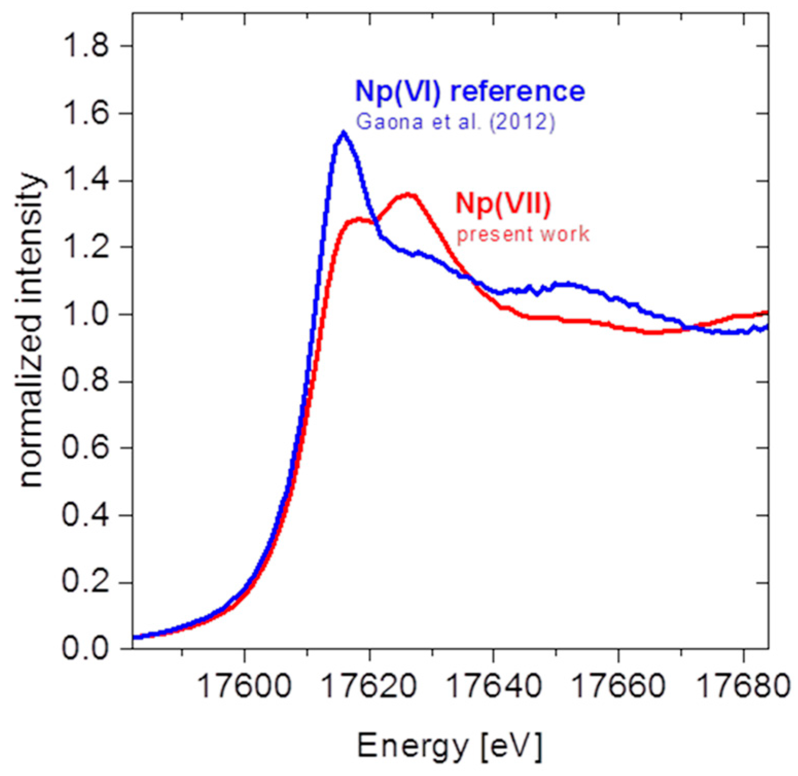
4.1. Aquatic Chemistry of Neptunium under Hyperalkaline and Oxidizing Conditions

Neptunium is a light actinide with electronic configuration [Rn] 5f4 6d1 7s2. It is characterized by a very rich redox chemistry comprising the formation of aqueous complexes and solid compounds in oxidation states +III to +VII, besides Np metal. Neptunium is the heaviest actinide that can form stable compounds by losing all its valence electrons as Np(VII) (the formation of Pu(VIII) compounds remains so far putative, as recently discussed in Clark et al. [23]). The +VII oxidation state can be stabilized in strongly alkaline solutions under very oxidizing conditions [24,25,26]. The predominance of the tetraoxo core geometry NpO4(OH)23− in the aqueous phase was previously confirmed by spectroscopy (in particular XAFS) and quantum chemical methods, e.g., [27,28,29,30,31,32]. The same anionic moiety was reported for a number of Np(VII) solid phases, mostly forming in the presence of alkaline cations (Na+, K+, Rb+, Cs+), e.g., [33,34]. Understanding the aquatic chemistry of higher oxidation states of the actinides is a topic of fundamental interest for the actinide community, but has also some applied perspectives with regard to highly alkaline radioactive wastes existing in different legacy sites, cf. [35,36] and references therein.
In spite of the number of spectroscopic and quantum chemical studies devoted to this topic, only a few studies provide insights on the thermodynamics of Np(VII) [37,38,39,40,41]. We further note that no thermodynamic data was selected for Np(VII) in the latest update volume of the NEA–TDB [24]. The present work provides a new approach for the investigation of the redox couple Np(VII)/Np(VI) using a combination of solubility experiments with spectroscopic techniques (UV-vis, XAFS) and solid phase characterization (XRD, quantitative chemical analysis). This study builds on our previous work on the thermodynamics on Np(VI) solubility and hydrolysis in dilute to concentrated NaCl–NaOH [42] and CaCl2 [43] solutions.

4.1.1. Experimental

Samples were prepared and stored in Ar-glove-boxes (O2 < 5 ppm). Batch solubility experiments were performed from undersaturation conditions using a 237Np(VI) solid phase prepared and characterized in our previous study, crystalline Na2Np2O7(cr) [42]. New solubility samples were prepared in NaCl–NaOH solutions with I = 1.0, 2.5 and 5.0 M and [NaOH] ≥ 1.0 M, containing 0.005 M or 0.05 M NaClO as an oxidizing agent. [Np] and Eh in the supernatant solutions were experimentally determined as described below, whereas pHm values were calculated from the given [OH] and the conditional ion product of water. The aqueous concentration of Np was measured by liquid scintillation counting (LSC, 1220 Quantulus instrument, Perkin Elmer) after 10 kD ultrafiltration. Aliquots for LSC analysis were mixed with 10 mL of LSC-cocktail Ultima Gold XR (Perkin-Elmer), and α-radiation of 237Np was measured after α/β-discrimination of the counts from the daughter nuclide 233Pa. Redox potentials were measured with a Pt combination electrode with Ag/AgCl reference system (Metrohm) and converted into Eh vs. standard hydrogen electrode (SHE).
The aqueous phase of the solubility sample in 5.0 M NaCl–NaOH with the highest [Np] was investigated by XAFS at the INE-Beamline. Approximately 300 μL of the suspension were transferred to a 400 μL polyethylene vial under Ar-atmosphere and centrifuged at 4020 g for 10 min. to obtain a compacted solid phase at the bottom of the vial. The vial was mounted in a gas-tight cell with Kapton® film (polyimide) windows inside the Ar-glovebox, and transported to the beamline where it was stored and measured under continuous flow of Ar. Np L3-edge XAFS spectra (E(Np0 2p3/2) = 17.61 keV) were recorded in fluorescence yield detection mode using an Ar-filled ionization chamber as I0-monitor and a 5-pixel LEGe detector (Canberra) to discriminate Np Lα fluorescence excited by the incoming beam, which was monochromatized by a pair of Ge<422> crystals (see [6] for experimental details). Energy calibration of the spectra was performed against the first derivative X-ray absorption near edge structure (XANES) spectrum of a zirconium metal foil (energy of first inflection point set to E(Zr0 1s) = 17.998 keV). XAFS data reduction and analysis were performed with ATHENA and ARTEMIS software of the Demeter 0.9.26 package following standard procedures [44].

4.1.2. Results and Discussion

Figure 2 shows the solubility data of Na2Np2O7(cr) in (a) 1.0, (b) 2.5 and (c) 5.0 M NaCl–NaOH solutions, as reported in [42] and determined in this work. The figure also indicates those samples for which UV-vis [42] and XAFS (present work) spectra were collected. Solid lines shown in the figure are calculated with the thermodynamic and activity models reported in [42] for the solubility and hydrolysis of Np(VI) in alkaline systems.
The agreement between experimental and calculated solubility data is satisfactory up to pHm ≈ 13, but model calculations significantly underestimate the experimental solubility above this pHm and with increasing hydroxide concentration. This observation strongly suggests the formation of additional aqueous species not considered in the original thermodynamic model reported in [42]. Considering the increased slope of the solubility curve in this pHm-region (slope ≈ +3), the newly formed aqueous species implies a larger Np: OH ratio than in the Np(VI) hydrolysis species described in [42], i.e., NpO2(OH)3 and NpO2(OH)42–.
The characterization by UV-vis of the supernatant solutions equilibrated in 1.0 M NaOH, 1.0 M NaOH + 1.5 M NaCl and 1.0 M + 4.0 M NaCl provides additional insights on the Np aqueous species prevailing in hyperalkaline pHm systems (Figure 3). The supernatant solutions investigated are characterized by a bright green colour, with two absorption bands in the visible region with maxima at λ = 411 nm (ε = 1490 ± 30 L⋅mol−1⋅cm−1) and λ = 612 nm (ε = 380 ± 20 L⋅mol−1⋅cm−1) [42]. These bands can be assigned to the formation of Np(VII) aqueous species, as previously reported for Np solutions in the presence of strong oxidizing systems (XeO3, Na4XeO6, K2S2O8, KIO4, NaBiO3, KClO, KBrO and O3) [45,46].
The UV-vis spectra with normalized absorbance shown in Figure 3 confirm that Np(VII) predominates in the aqueous phase of the samples equilibrated in 1.0 M NaOH + 1.5 M NaCl and 1.0 M + 4.0 M NaCl. The decreased normalized absorbance observed for the sample equilibrated in 1.0 M NaOH supports the presence of additional species in solution besides Np(VII), most likely corresponding to the Np(VI) hydrolysis species expected to prevail in this pHm-range, i.e., NpO2(OH)42–. The use of the extinction coefficient ε = (1490 ± 30) L⋅mol−1⋅cm−1 at λ = 411 nm to calculate the fraction of Np(VII) in the aqueous solution equilibrated in 1.0 M NaOH results in a redox distribution of 63% Np(VII) and 37% of Np(VI). The redox potential (pe) measured for the sample equilibrated in 1.0 M NaOH resulted in pe = (9.6 ± 0.5) or Eh = (570 ± 30) mV (with pe = 16.9⋅Eh, in V) (see Figure 2 and [42]). This value is in line with formal potentials reported in the literature for the redox couple Np(VII)/Np(VI) in 1.0 M NaOH [38,39,40,41] (see Table 1), although noting that Eh values reported in the present study are not corrected for the liquid junction potential of the redox electrode.
XANES and EXAFS were used to resolve the redox state and chemical structure of the Np aqueous species prevailing in hyperalkaline oxidizing solutions. Figure 4 shows the XANES spectra of the supernatant solution investigated in this work (2.0 M NaOH + 3.0 M NaCl), compared to the XANES reference spectra reported in [10] for Np(VI) in alkaline conditions. The XANES spectrum obtained in this work shows a pre-edge shoulder similar in energy to the main edge of the Np(VI) reference, further developing in a positive shift of the edge rise and edge peak as previously reported in the literature for Np(VII) aqueous species forming in oxidizing solutions with [NaOH] ≥ 1.0 M [27,28,29,30]. These changes in the XANES spectra reflect a coordination environment that is significantly different from the linear trans-dioxo Np(VI)O22+ configuration.
Experimental and theoretical k2-weighted Np L3-EXAFS spectra and their corresponding Fourier transforms are shown in Figure 5. Structural parameters resulting from the fit are summarized in Table 2, together with structural data reported in the literature for Np(VII) and Np(VI) aqueous species forming in hyperalkaline, oxidizing conditions. The fit of two oxygen shells with NO1 = 4 at R = 1.90 ± 0.005 Å and NO2 = 3.4 ± 0.9 at R = 2.32 ± 0.01 Å is sufficient to satisfactorily reproduce the experimental k2-weighted EXAFS spectrum and corresponding Fourier transform (R-factor = 0.006). These values are consistent with coordination numbers and distances reported for Np(VII) aqueous species by Bolvin et al. [28] and Ikeda-Ohno et al. [30], and significantly differ from the structural parameters reported for the Np(VI) species prevailing in hyperalkaline systems, NpO2(OH)42– (Nax ≈ 2 and Neq ≈ 4 at R = 1.80 and 2.23–2.25 Å, respectively [47,48]). They are widely acknowledged to correspond to the Np(VII) species NpO4(OH)23–, bearing in mind the large uncertainty associated with the coordination number N and its high correlation with the Debye-Waller factor σ2.
The combination of solubility data, slope analysis, solid phase characterization and aqueous speciation (UV–vis, XAFS) provides new insights for the interpretation of the chemical behaviour of neptunium in hyperalkaline oxidizing systems. Although the aqueous-aqueous system for the Np(VII)/Np(VI) couple (1) has been previously described in a number of studies [29,37,38,39], this is the first attempt to quantitatively assess the Np(VII)/Np(VI) redox equilibrium on the basis of a solid-aqueous equilibrium (2). Note, however, that a systematic characterization of the redox potential, including a correction for the liquid junction potential of the redox electrode in highly concentrated hydroxide solutions, is required for a definitive thermodynamic description of the system. This was beyond the scope of this study, and the proposed approach is only shown exemplarily in this contribution.
Aqueous-aqueous system (UV-vis, EXAFS):
NpO2(OH)42− + 2 OH ⇔ NpO4(OH)23− + e + 2 H2O(1)
log K°VIaq-VIIaq = log [NpO4(OH)23−] + log γ {NpO4(OH)23−} − pe + 2 log aw − log [NpO2(OH)42−]
         − log γ {NpO2(OH)42−} − 2 log [OH] − 2 log γ {OH}
Solid-aqueous system (solubility, UV-vis, EXAFS):
0.5 Na2Np2O7(cr) + 3 OH ⇔ NpO4(OH)23−+ Na+ + e + 0.5 H2O(1)
log K°VIs-VIIaq = log [NpO4(OH)23−] + log γ {NpO4(OH)23−} + log [Na+] + log γ {Na+} − pe + 0.5 log aw
                  − 3 log [OH] − 3 log γ {OH}
where KVIaq−VIIaq and KVIs−VIIaq are the equilibrium constants corresponding to the redox reactions (1) and (2), respectively, γ is the activity coefficient of a given ion, aw is the activity of water and pe is the apparent electron activity (pe = −log ae−) calculated from the experimentally measured redox potential (Eh, in V). The use of solubility experiments with a well-defined Np(VI) solid phase and the key input on the aqueous speciation of Np(VII) provided by XAFS represent a new approach to characterizing the thermodynamic properties of Np(VII). In combination with our previous work on the thermodynamics of Np(VI) in alkaline solutions [42], and with the NEA–TDB selection for Np(V) and Np(IV) systems [24], this approach gives rise to the possibility of accurately calculating the aqueous speciation and solubility (e.g., Pourbaix and solubility diagrams) of Np in alkaline to hyperalkaline pH systems, from reducing to very oxidizing conditions.

4.2. Speciation of Actinides in a Spent Nuclear Fuel (Snf) Bulk Fragment

Many countries employing nuclear power generation have opted for an open nuclear fuel cycle, and SNF is thus considered as a waste form for which direct disposal in a deep geological repository is envisaged. On a global scale, about 10,000 metric tons of heavy metal (mainly uranium) are processed each year by nuclear power reactors, and a cumulative inventory of approximately 367,000 metric tons of SNF is stored either in pools or dry casks at the sites of nuclear power plants or in centralized interim storage facilities [49]. Fresh nuclear fuel for boiling water (BWR) or pressurized water reactors (PWR) is a ceramic matrix mainly formed by 238UO2 with varying enrichments of fissile 235U (up to 5%). At a typical burn-up of 35 to 45 GWd/tHM, about 4–5% of the initial U metal atoms have been converted, either by fission or neutron capture [1,50]. Speciation and mobility of the fission products in the fuel matrix is controlled by their thermodynamic properties in the temperature field of the fuel rods under operation conditions. The centerline temperatures of fuel rods are typically in the range of 1000 °C to 1200 °C, whereas the rim temperatures are controlled by the coolant (about 300 °C in PWRs). While lanthanides (formed as fission products) and actinides (formed from initial 238U through consecutive neutron capture and β-decay) are assumed to be incorporated within the UO2 fluorite-type structure, some highly mobile fission products (e.g., iodine and cesium) are known to be partly segregated from the fuel matrix and may accumulate at UO2 grain boundaries, fractures and the gap between pellets and the cladding tube. Other fission products form metallic precipitates (“Ɛ-phases”), comprising noble metals as well as Mo, Tc and Te [51,52].
In view of the expected SNF interim storage prolongation before the availability of a final disposal facility, and the necessity to quantify potential radionuclide release mechanisms from the SNF matrix following canister corrosion in a geological repository, direct speciation investigations determining the physical and chemical state of actinides and fission products in the SNF matrix are mandatory. However, due to the high γ-dose rate of SNF after discharge from the reactor (mainly determined by short-lived 137Cs), handling of even tiny SNF fragments poses a challenge from radiation safety and speciation method point of view. Thus, such measurements described in the literature are scarce. Nevertheless, due to the high penetration strength of medium energy to hard X-rays, XAS enables the investigation of well-encapsulated SNF specimens. This has been demonstrated in the pioneering work by C. Degueldre [53,54,55,56,57,58], E. Curti [59] and coworkers at PSI, Switzerland, focusing on actinide (U, Pu, Am, Cm) and fission products (Se, Kr) speciation. To minimize the activity of the samples transferred to the micro-XAS station at the Swiss Light Source (SLS), Degueldre et al. [53]. applied a “peeling technique”, where SNF microparticles are removed from a fuel pellet section by a piece of adhesive Kapton® tape pressed against the polished fuel section surface.

4.2.1. Experimental

Work at KIT-INE currently focuses on direct XAFS/XES speciation investigations of SNF bulk fragments and cladding ring segments (both from the plenum and the central section, where the Zircaloy had been in contact with the fuel during irradiation), originating from a test fuel rod irradiated at Gösgen PWR, Switzerland (238UO2 fuel with an initial enrichment of 3.8% 235U, burn-up ~50.4 GWd/tHM corresponding to ~5% FIMA (fissions per initial metal atom)) [60]. Sample preparation for experiments at the INE-Beamline and ACT station follows the procedure described by Dardenne et al. [16] for the investigation of a borosilicate waste glass fragment (cf. Section 3). Here, we present initial results on actinide and Zr speciation obtained for a SNF fragment sampled from the core region of a fuel rod section. The selected mm-sized fragment was removed from the shielded box in a clean vial, transferred to a ventilated hood, and placed in the central cavity of a Plexiglas disk acting as sample holder (Figure 6). The cavity was covered by two crossed layers of adhesive Kapton® tape (first containment) and the disk sealed in a polyethylene bag (second containment). The dose rate of the sealed sample was determined to be 3.45 mSv/h in contact and ~2 µSv/h at 1 m distance, i.e., at the edge of the beamline experimental table. At the beamline (U was measured at the INE-Beamline, all other elements at ACT), the disk was mounted in a stand and positioned at 45° relative to the impinging synchrotron beam and to the fluorescence detector (5-pixel Canberra LEGe, Figure 6, image on the right-hand side). Rough sample positioning was achieved by an alignment laser hitting the sample cavity, and fine positioning was remotely performed by collecting the U Lα1 fluorescence (~13.61 keV) intensity during an x/z-raster scan. XAFS data were recorded in fluorescence yield mode at the U L3-(17.166 keV), Pu L3-(18.057 keV), Am L3-(18.510 keV) and Zr K-edge (17.998 keV), detecting U Lα1, Pu Lα1, Am Lα1 and Zr Kα1,2 fluorescence emission, respectively, using an Ar-filled ionization chamber as I0-monitor. Energy calibration of the spectra was performed against the first derivative XANES spectrum of an yttrium metal foil (energy of first inflection point set to E(Y0 1s) = 17.038 keV), and a zirconium metal foil (energy of first inflection point set to E(Zr0 1s) = 17.998 keV), for U L3- and Pu L3-, Am L3-, Zr K-edge measurements, respectively. All reference samples (with the exception of Am(III)aq) were measured in standard transmission mode using two Ar-filled ionization chambers. As in the previous section, XAFS data reduction and analysis were performed with ATHENA and ARTEMIS software of the Demeter 0.9.26 package [44].

4.2.2. Results and Discussion

Table 3 lists the theoretical atom percentages of the irradiated Gösgen PWR fuel, summed per element over all isotopes as calculated for actinides and zirconium, employing the MCNPX-CINDER code with the ENDF-7 reference data base library [61,62]. Np (261 ppm) and Cm (16 ppm) fall below the detection limit for XAS. Note that detection of the Lα fluorescence radiation of the minor actinides is strongly hampered by reabsorption in the dense UO2 matrix. With its (theoretical) content of 545 ppm, Am was the actinide element with the lowest concentration present in the SNF fragment where we were able to obtain reasonable XAFS data. Investigations of the fission elements constituting metallic fuel inclusions (Mo – Tc – Ru – Rh – Pd – Te) and fission products Se, Cs and I at their respective K-edges (i.e., well above or below (Se) the U L3 absorption edge) will be the subject of a forthcoming publication.
Figure 7 (left) depicts the fluorescence mode U L3-XANES spectra obtained for the SNF fragment compared to a reference spectrum taken from an UO2 pellet (uraninite dispersed in polyethylene powder and pressed to a disk) with an ideal edge-jump for transmission measurements. The spectrum of the SNF fragment strongly resembles that of U(IV) in the fluorite type UO2 reference. The position of the white line (WL) maximum (17.176 keV) and the first inflection point (17.170 keV) clearly point to the prevailing tetravalent oxidation state of uranium [63] in SNF, while WL broadening and damping as well as EXAFS amplitude losses visible in Figure 7 (left) have to be attributed to a marked “self-absorption” effect, i.e., the well-known non-linearity when detecting XAFS of a concentrated element in a “thick” sample in total fluorescence yield mode [64]. The sensitivity of the present U L3 bulk XAS measurement does not allow the detection of possible U species in a chemical state deviating from uraninite as might possibly result from charge compensation effects upon incorporation of trivalent fission lanthanide or actinide elements in the U-dioxide matrix (cf. discussion on Am below). Considering the overall low total yield of fission lanthanides (in total 1.1 at.%) and transuranium elements (with the exception of Pu, present at 3700 ppm) generated during fuel burn-up, such interactions might be—if at all—only detectable close to the rim of the fuel pellet, where a “high burn-up structure” forms due to higher neutron flux.
Pu adopts the same fluorite-type crystal structure of a tetravalent cation in the SNF matrix as its U mother, as obvious from the fluorescence mode Pu L3-XANES shown in Figure 7 (right) and comparison to a PuO2 reference sample. The spectrum of the SNF fragment is unaffected by“self absorption” compared to that obtained for U. The Pu L3-EXAFS data of the fuel and the reference (not shown) are almost congruent, with the exception of a higher noise level present for the fuel spectrum.
WL and edge positions recorded at the Zr K-edge for the SNF fragment and the monoclinic Zr(IV)O2 reference sample (Figure 7, right) are in agreement with the presence of Zr as a tetravalent fission product cation (generated at about the same efficiency as Pu). The Zr-spectrum of the SNF fragment exhibits a narrower, more symmetric WL, and a reduced energy distance between the WL maximum and the first shape resonance compared to monoclinic ZrO2. These small, but significant, differences might indicate more symmetric oxygen coordination in the fuel compared to the reference oxide (m-ZrO2: seven-fold O-coordination with seven different Zr-O distances between 2.051 and 2.285 Å [65]) as expected if Zr(IV) remains predominantly incorporated at U(IV) sites in the UO2 fluorite type lattice, cf. [51].
Finally, Figure 8 depicts the Am L3-edge XANES obtained for the SNF fragment, a solid Am(IV)O2 and an aqueous Am(III) reference sample ([Am] = 4 mM in 0.05 M HClO4)—the latter also measured in fluorescence detection mode (data from [16]). Comparing these XANES spectra, we can conclude that—in contrast to U and Pu, which are incorporated as tetravalent cations in the SNF matrix—Am retains its favoured trivalent oxidation state. Am isotopes are generated during fuel irradiation through β-decay of 241Pu and consecutive neutron capture. Since recoil-induced Am-cation displacement in the UO2 lattice is not to be expected, the necessary charge balance might occur via formation of Am(III)O711− moieties with oxygen vacancies in the cubic, eight-fold coordinated cation site of the fluorite structure. Alternatively, UO2 can act as redox buffer:
Am(IV) → Am(III)/UO2 → UO2+x
This process has been observed by, e.g., D. Prieur et al. in their study on Am/U oxide solid solution formation [12]. As discussed above, the resulting minor UO2+x fraction is not detectable in the present work and might require a combination of spatially resolved and high (energy) resolution XAS techniques (i.e., U M-edge HERFD/PFY/HR-XANES, e.g., [66,67,68,69]) in future studies. The latter techniques have been shown to be especially powerful to unravel minor actinide oxidation states in complex mixtures (cf. Section 4.3).
To summarize—our findings for U, Pu and Am in a SNF bulk fragment are in good agreement with the aforementioned investigations reported by Degueldre et al. for the behaviour of these elements in microparticles of irradiated (U,Pu)O2 MOX fuel (60 GWd/tHM) [53,54,57].

4.3. High Resolution Xanes Study of the Influence Of Fe(II) on the Redox State of U Sorbed on Magnetite

A number of laboratory studies have been performed to clarify the fate of U(VI) upon interaction with magnetite [70,71,72,73]. U is known to occur in two environmentally relevant redox states—U(IV) and U(VI). The chemical behavior of the intermediate U(V) state is poorly understood and its environmental significance has been questioned. During U interaction with Fe(II)/Fe(III), kinetic effects may cause U to be present in mixed redox states. Due to the lack of reliable and sensitive detection methods, only a few studies have considered the significance of U(V) for U containing (geo)chemical systems [74,75,76]. Recently, Pidchenko et al. investigated the co-precipitation of U(VI) with magnetite nanoparticles at uranium loadings varying between 1000 and 10000 ppm by different XAS techniques and XPS [77]. It has been demonstrated that the advanced U M4-edge high energy resolution XANES method (HR-XANES) is capable of clearly differentiating U(IV), U(V), and U(VI) coexisting in the same sample. U L3-EXAFS and TEM revealed that initially sorbed U(VI) species recrystallize to non-stoichiometric UO2+x nanoparticles when stored under anoxic conditions. These U species oxidize again when exposed to air. U M4 HR-XANES in combination with U L3-EXAFS revealed that U(V) can remain stable for months under ambient conditions, probably protected from oxidation by incorporation into octahedral magnetite sites. These investigations have been augmented by U L3/M4-edge HR-XANES and U 4f/Fe 2p XPS studies of batch-type U(VI)/magnetite/maghemite sorption systems presented in this section.

4.3.1. Experimental

Magnetite nanoparticles were prepared by reaction of FeSO4 with KOH and KNO3 [78] under Ar atmosphere in a glovebox (< 2 ppm O2). The freshly prepared magnetite suspension was dialyzed against deionized water until the electrical conductivity was comparable to that in deionized water (4 µS/cm). The magnetite concentration in the prepared suspension was 50.5 g/L. The suspension was stored in an Ar glovebox prior to the batch experiments. Maghemite was prepared by heating the freeze-dried magnetite suspension in a dry box at 250 °C for 2 h under ambient conditions. Batch sorption experiments were conducted in a glove box equipped with pH and Eh electrodes under Ar atmosphere at room temperature (25 °C). A magnetite suspension (2 g/L) was prepared by diluting the stock suspension with Ar-purged Milli-Q water (18 µS/cm). The background electrolyte concentration (NaCl) was adjusted to 0.02 M. U(VI) (uranyl chloride solution, pH ~2.5) was added to the magnetite suspension in small portions to avoid U(VI) precipitation. The final U concentration was 3 × 10⁻⁵ M. The pH of the resulting suspension was immediately adjusted to approximate neutral values—variations were continuously recorded during the experiment. The maghemite batch experiment was performed in an analogue fashion. Eh was recorded simultaneously for each pH measurement. After 175 days of interaction time, a calculated amount of aqueous Fe(II) (0.36 mg) was added to a 5 ml portion of magnetite batch suspension to recrystallize magnetite closer to its stoichiometric Fe(II)/Fetot ratio of 0.33. The amount of Fe(II) was estimated by analyzing XPS spectra measured for the as-prepared and reacted magnetite. For XPS analysis and HR-XANES, the required amount of solid phases was separated from the supernatant inside the glove box using a magnet and then transferred to specific sample holders or sealed sample cells, respectively (cf. Table 4 for sample details).
XPS measurements were carried using an ULVAC-PHI VersaProbe II instrument equipped with a monochromatized Al Kα X-ray source (1486.7 eV) operated at 33 W source power. Calibration of the binding energy scale of the spectrometer was performed using well-established binding energies of elemental lines of pure metals (surface cleaned by Ar ion beam sputtering, monochromatic Al Kα: Cu 2p3/2 at 932.62 eV, Au 4f7/2 at 83.96 eV [79]). The HR-XANES experiments were performed at the INE-Beamline and at beamline ID26 at the European Synchrotron Radiation Facility (ESRF). At ID26, the incident X-ray beam was monochromatized by a pair of Si(311) (U L3-edge, E = 17.166 keV) or Si(111) (U M4-edge, E = 3.728 keV) crystals in the DCM, respectively. The beam was focused to ~150 µm vertical and 450 µm horizontal size. At the INE-Beamline, a pair of Ge(422) or Si(111) crystals in the DCM was used for U L3- or U M4-edge measurements and the beam was focused to a ~500 µm horizontal and vertical spot at the sample position. At both stations, HR-XANES spectra were recorded using a Johann-type 5-analyzer-crystal X-ray emission spectrometer with 1 m Rowland circles [7,80] The U L3/M4 edge spectra were obtained by recording the maximum intensity of the U Lα1/Mβ emission lines as function of the excitation energy. The Ge(777) / Si(220) diffraction order of five spherical Ge(111) / Si(110) crystal analyzers with 1 m radius of curvature were used to isolate the U Lα1 (E = 13.614 keV) and U Mβ (E = 3.337 keV) fluorescence energies, respectively.

4.3.2. Results and Discussion

Powder XRD analysis (not shown) has confirmed the formation of magnetite and maghemite particles used for the batch sorption experiments. U is already quantitatively removed from solution by magnetite after 29 days of interaction time. There are two most likely mechanisms for U(VI) immobilization-sorption on the mineral surface and precipitation as a solid phase. U(VI) can be reduced to form mixed U(IV)/U(V) or U(VI)/U(V) oxy/hydroxide species [81].
The XP spectra for Um175 and Um175f in the region of the 4f binding energy are depicted in Figure 9a. The O 1s binding energy at 530.2 eV measured for the same sample was used to calibrate the energy positions of the U 4f peaks. Both spectra exhibit a splitting of the U 4f7/2,5/2 doublet. Fitting of the 4f7/2 peaks reveals two components, centered at 380.5 eV and 381.8 eV—characteristic of U(V) and U(VI), respectively [74]. The intensities of the U(V) main peak and the satellite structure obtained for sample Um175f (after addition of Fe(II) to the Um175 sample) are increased compared to the Um175 sample. The fit analysis reveals a contribution of ~45% and ~55% U(V) to the spectra of Um175 and Um175f, respectively. No main or satellite peaks characteristic for the presence of U(IV) are visible in any of the spectra, as expected at the relatively high Eh values of the batch experiments. Figure 9b depicts the corresponding XP spectra in the region of the Fe 2p binding energies. The amount of structural Fe(II) in the reacted magnetite samples is decreasing compared to stoichiometric magnetite as obvious from the decreasing Fe(II) contribution at ~708.0 eV.
The U L3-edge HR-XANES spectra of Um175, Um175f, Umh and an U4O9 reference sample are depicted in Figure 10c,d. While U4O9 is known to contain 50% U(IV) and 50% U(V) [82], it has been previously shown that the U oxidation state in Umh (U(VI) adsorbed on maghemite) stays +VI [77], as expected, due to the absence of Fe(II) cations in the mineral structure. Hence, the Umh WL position (G) is shifted by 1.6 eV to higher energies compared to the WL position (F) in the U4O9 spectrum. Note that the WL energy positions obtained for Um175f, Um175 and Umh are very similar. The WLs are broader and the post-edge feature at about 17186.5 eV is less defined for the Um175 and Um175f spectra compared to the Umh spectrum (feature H, Figure 10c,d). Feature H is characteristic for the multiple scattering of the U 2p3/2 photoelectron from the two axial O atoms in U(V)/U(VI) “uranyl” trans-dioxo moieties. These results suggest that the U(V)/U(VI) species found by XPS in the Um175 and Um175f samples are not solely present as uranyl-type species. U(V)/U(VI) are also known to form long axial U-O bonds (bond lengths > 2 Å), which might be assigned to “uranate” species. In this case, a shift of the XANES spectra to higher energies compared to the uranyl moieties is observed [83,84]. Hence, WL broadening in the case of Um175 and Um175f might be explained by the presence of mixed U redox states, in addition to disorder effects due to varying U-Oax distances in these samples. Thus, although the U L3-edge HR-XANES technique is definitely more sensitive compared to the conventional total fluorescence yield detection method [85], clear identification of U(V) failed due to the contribution of still broadened spectral features.
With markedly reduced core-hole lifetime-broadening effects, HR-XANES spectra recorded at the U M4-edge resolve significantly more details on mixed U redox states in the magnetite batch samples. U M4-edge HR-XANES spectra of Um175, Um175f, Umh and the U4O9 reference sample are shown in Figure 10a,b. The energy positions of peaks C, D and E are very similar for Um175 and Umh. This observation clearly indicates that U(VI) dominates U speciation in Um175. The U(V) contribution detected by XPS, which is missing in the HR-XANES of this sample, can be attributed to the different penetration depths of both techniques. XPS probes only the surface layer (a few nm), whereas the U M4-edge HR-XANES is a bulk sensitive method with an information depth of several µm. Hence, comparison of these spectroscopy techniques suggests that U(V) in the Um175 sample is exclusively formed in a thin surface layer. The main peak C of the Um175f spectrum is shifted by ~0.2 eV to lower energies towards peak B of the U4O9 spectrum—the latter one characteristic for U(V) (note that peak A in the U4O9 spectrum is characteristic for the presence of U(IV), where minor contributions might only be present for Um175f, cf. Figure 10b). This experimental evidence confirms substantial U(V) contributions to the bulk structure of the Um175f sample. The intensities of peaks D and E significantly decrease for Um175 and Um175f compared to Umh, and additionally, peak E slightly shifts to higher energy in the case of Um175, indicating an elongation of the U-Oax bond for this sample [86]. This might be another hint that U(V)/U(VI) do not solely form uranyl-type bonds in theses samples, as already discussed above.

5. Outlook

Future radionuclide research at the KIT synchrotron source will focus on the tremendous capabilities of high (energy) resolution X-ray emission spectroscopy. This technique is meanwhile fully operational at ACT—including an He-filled box enclosing all beam paths at actinide M-edge energy measurements for HR-XANES and elastic and inelastic X-ray scattering experiments (RIXS, NIXS) on safety relevant actinide and long-lived fission product sample systems. These methods are to date not fully exploited in radioactive matter sciences. Further emphasis at both stations is currently placed on the improvement of spatial resolution for XAS/XES/XRF/XRD experiments by implementing a refocusing Kirkpatrick-Baez mirror optic at ACT and an improved poly-capillary optic at the INE-Beamline. Procurement and implementation of advanced detector devices for, e.g., high energy X-ray fluorescence detection and Laue-type high energy X-ray diffraction/total scattering measurements at ACT (up to ~55 keV) are also in progress. Although the proposal-based user operation at the KIT synchrotron source has been terminated in 2015, both experimental stations will stay open to serve the radionuclide science community in future collaborative projects in the fields of nuclear waste disposal safety as well as basic actinide and radionuclide research.

Author Contributions

Conceptualization, J.R.; Investigation, J.R., R.D., K.D., D.F., X.G., E.G.-R.C., M.H., K.O.K., I.P., D.S. and T.V.; Supervision, H.G.; Writing—original draft, J.R., X.G. and I.P.; Writing—review & editing, M.A., V.M. and H.G.

Funding

This research was partly funded by the Helmholtz Association of German Research Centres (HGF) and KIT through the Helmholtz Young Investigator Group Grant No. VH-NG-734 awarded to T.V. and the European Commission, Joint Research Centre Karlsruhe (JRC-KA).

Acknowledgments

The KIT Institute for Beam Physics and Technology (IBPT) is acknowledged for the operation of the storage ring, the Karlsruhe Research Accelerator (KARA), and provision of beamtime at the KIT light source. We also thank the European Synchrotron Radiation Facility ESRF for granting additional beamtime for HR-XANES experiments at beamline ID26. Furthermore, we need to thank T. Prüßmann for software development at CAT-ACT and N. Müller, G. Christill, T. Hoffmann and Ch. Marquardt for technical and administrative support during conditioning and transport of HLW samples to the light source. S. Doyle (KIT-IPS) is acknowledged for proofreading the manuscript.

Conflicts of Interest

The authors declare no conflicts of interest.

References

  1. Ewing, R.C. Long-term storage of spent nuclear fuel. Nat. Mater. 2015, 14, 254–257. [Google Scholar] [CrossRef] [PubMed]
  2. Ewing, R.C.; Whittleston, R.A.; Yardley, B.W.D. Geological disposal of nuclear waste: A primer. Elements 2016, 12, 234–239. [Google Scholar] [CrossRef]
  3. Zimina, A.; Dardenne, K.; Denecke, M.A.; Grunwald, J.-D.; Huttel, E.; Lichtenberg, H.; Mangold, S.; Prüßmann, T.; Rothe, J.; Steininger, R.; et al. The CAT-ACT Beamline at ANKA: A new high energy X-ray spectroscopy facility for CATalysis and ACTinide research. J. Phys. Conf. Ser. 2016, 712, 012019. [Google Scholar] [CrossRef]
  4. The KIT Institute for Beam Physics and Technology (IBPT). Available online: www.ibpt.kit.edu/ (accessed on 11 December 2018).
  5. Denecke, M.A. X-ray Spectroscopy in Studies of the Nuclear Fuel Cycle. In X-ray Absorption and X-ray Emission Spectroscopy: Theory and Applications; van Bokhoven, J.A., Lamberti, C., Eds.; John Wiley & Sons Ltd.: Hoboken, NJ, USA, 2016; ISBN 978-1-118-84428-1. [Google Scholar]
  6. Rothe, J.; Butorin, S.; Dardenne, K.; Denecke, M.A.; Kienzler, B.; Löble, M.; Metz, V.; Seibert, A.; Steppert, M.; Vitova, T.; et al. The INE-Beamline for actinide science at ANKA. Rev. Sci. Instrum. 2012, 83, 043105. [Google Scholar] [CrossRef] [PubMed]
  7. Zimina, A.; Dardenne, K.; Denecke, M.A.; Doronkin, D.E.; Huttel, E.; Lichtenberg, H.; Mangold, S.; Prüßmann, T.; Rothe, J.; Spangenberg, T.; et al. CAT-ACT—A new highly versatile X-ray spectroscopy beamline for catalysis and radionuclide science at the KIT synchrotron light facility ANKA. Rev. Sci. Instrum. 2017, 88, 113113. [Google Scholar] [CrossRef] [PubMed]
  8. Transnational Access to Large Infrastructure for a Safe Management of ActiNide (TALISMAN). Available online: www.actinet-i3.eu/ (accessed on 11 December 2018).
  9. Hennig, C.; Tutschku, J.; Rossberg, A.; Bernhard, G.; Scheinost, A.C. Comparative EXAFS Investigation of Uranium(VI) and -(IV) Aquo Chloro Complexes in Solution Using a Newly Developed Spectroelectrochemical Cell. Inorg. Chem. 2005, 44, 6655–6661. [Google Scholar] [CrossRef] [PubMed]
  10. Gaona, X.; Tits, J.; Dardenne, K.; Liu, X.; Rothe, J.; Denecke, M.A.; Wieland, E.; Altmaier, M. Spectroscopic investigations of Np(V/VI) redox speciation in hyperalkaline TMA-(OH,Cl) solutions. Radiochim. Acta 2012, 100, 759–770. [Google Scholar] [CrossRef]
  11. Skerencak-Frech, A.; Fröhlich, D.R.; Rothe, J.; Dardenne, K.; Panak, P.J. Combined Time-Resolved Laser Fluorescence Spectroscopy and Extended X-ray Absorption Fine Structure Spectroscopy Study on the Complexation of Trivalent Actinides with Chloride at T = 25–200 degrees C. Inorg. Chem. 2014, 53, 1062–1069. [Google Scholar] [CrossRef]
  12. Prieur, D.; Lebreton, F.; Caisso, M.; Martin, P.M.; Scheinost, A.C.; Delahaye, T.; Manara, D. Melting behaviour of americium-doped uranium dioxide. J. Chem. Thermodyn. 2016, 97, 244–252. [Google Scholar] [CrossRef]
  13. Lebreton, F.; Horlait, D.; Delahaye, T.; Blanchart, P. Fabrication and characterization of U1−xAmxO2±δ compounds with high americium contents (x = 0.3, 0.4 and 0.5). J. Nucl. Mater. 2013, 439, 99–102. [Google Scholar] [CrossRef]
  14. Caisso, M.; Picart, S.; Belin, R.C.; Lebreton, F.; Martin, P.M.; Dardenne, K.; Rothe, J.; Neuville, D.R.; Delahaye, T.; Ayral, A. In situ characterization of uranium and americium oxide solid solution formation for CRMP process: First combination of in situ XRD and XANES measurements. Dalton Trans. 2015, 44, 6391–6399. [Google Scholar] [CrossRef] [PubMed]
  15. Fleisch, J.; Grünewald, W.; Roth, G.; Schmitz, F.-J.; Tobie, W.; Weishaupt, M. Successful Hot Operation of the German Vitrification Plant VEK—Results and Experiences. In Proceedings of the WM 2012-Conference, Phoenix, AZ, USA, 26 February–1 March 2012; No. 11277. pp. 1–7. [Google Scholar]
  16. Dardenne, K.; González-Robles, E.; Rothe, J.; Müller, N.; Christill, G.; Lemmer, D.; Praetorius, R.; Kienzler, B.; Metz, V.; Roth, G.; et al. XAS and XRF investigation of a genuine HAWC glass fragment obtained from the Karlsruhe vitrification plant (VEK). J. Nucl. Mater. 2015, 460, 209–215. [Google Scholar] [CrossRef]
  17. Grambow, B. Nuclear waste glasses—How durable. Elements 2006, 2, 357–364. [Google Scholar] [CrossRef]
  18. Rothe, J.; Walther, C.; Denecke, M.A.; Fanghänel, T. XAFS and LIBD Investigation of the Formation and Structure of Colloidal Pu(IV) Hydrolysis Products. Inorg. Chem. 2004, 43, 4708–4718. [Google Scholar] [CrossRef] [PubMed]
  19. Walther, C.; Rothe, J.; Brendebach, B.; Fuss, M.; Altmaier, M.; Marquardt, C.M.; Büchner, S.; Cho, H.-R.; Yun, J.-I.; Seibert, A. New insights in the formation processes of Pu(IV) colloids. Radiochim. Acta 2009, 97, 199–207. [Google Scholar] [CrossRef]
  20. Kersting, A.B. Plutonium Transport in the Environment. Inorg. Chem. 2013, 52, 3533–3546. [Google Scholar] [CrossRef] [PubMed]
  21. Tasi, A.; Gaona, X.; Fellhauer, D.; Böttle, M.; Rothe, J.; Dardenne, K.; Schild, D.; Grivé, M.; Colàs, E.; Bruno, J.; et al. Redox behavior and solubility of plutonium under alkaline, reducing conditions. Radiochim. Acta 2018, 106, 259–279. [Google Scholar] [CrossRef]
  22. Tasi, A.; Gaona, X.; Fellhauer, D.; Böttle, M.; Rothe, J.; Dardenne, K.; Polly, R.; Grivé, M.; Colàs, E.; Bruno, J.; et al. Thermodynamic description of the plutonium–α–d–isosaccharinic acid system ii: Formation of quaternary Ca(II)–Pu(IV)–OH–ISA complexes. Appl. Geochem. 2018, 98, 351–366. [Google Scholar] [CrossRef]
  23. Clark, D.L.; Geeson, D.A.; Hanrahan, R.J., Jr. (Eds.) Plutonium Handbook, 2nd ed.; American Nuclear Society: La Grange Park, IL, USA, 2018. [Google Scholar]
  24. Guillaumont, R.; Fanghänel, T.; Fuger, J.; Grenthe, I.; Neck, V.; Palmer, D.A.; Rand, M.H. Update on the Chemical Thermodynamics of U, Np, Pu, Am and Tc; Elsevier: Amsterdam, The Netherlands, 2003. [Google Scholar]
  25. Morss, L.R.; Edelstein, N.M.; Fuger, J.; Katz, J.J. (Eds.) The Chemistry of the Actinide and Transactinide Elements; Springer: Dordrecht, The Netherlands, 2006. [Google Scholar]
  26. Altmaier, M.; Gaona, X.; Fanghänel, T. Recent Advances in Aqueous Actinide Chemistry and Thermodynamics. Chem. Rev. 2013, 113, 901–943. [Google Scholar] [CrossRef] [PubMed]
  27. Williams, C.W.; Blaudeau, J.P.; Sullivan, J.C.; Antonio, M.R.; Bursten, B.; Soderholm, L. The Coordination Geometry of Np(VII) in Alkaline Solution. J. Am. Chem. Soc. 2001, 123, 4346–4347. [Google Scholar] [CrossRef] [PubMed]
  28. Bolvin, H.; Wahlgren, U.; Moll, H.; Reich, T.; Geipel, G.; Fanghänel, T.; Grenthe, I. On the structure of Np(VI) and Np(VII) species in alkaline solution studied by EXAFS and quantum chemical methods. J. Phys. Chem. A 2001, 105, 11441–11445. [Google Scholar] [CrossRef]
  29. Clark, D.L.; Palmer, P.D.; Tait, C.D.; Webster Keogh, D.W.; Conradson, S.D.; Donohoe, R.J. Actinide Research Quarterly 2004, 1st Quarter. Available online: https://www.lanl.gov/orgs/nmt/nmtdo/AQarchive/04spring/ (accessed on 11 December 2018).
  30. Ikeda-Ohno, A.; Tsushima, S.; Takao, K.; Rossberg, A.; Funke, H.; Scheinost, A.C.; Bernhard, G.; Yaita, T.; Hennig, C. Neptunium Carbonato Complexes in Aqueous Solution: An Electrochemical, Spectroscopic, and Quantum Chemical Study. Inorg. Chem. 2009, 48, 11779–11787. [Google Scholar] [CrossRef]
  31. Lozano, J.M.; Clark, D.L.; Conradson, S.D.; Den Auwer, C.; Fillaux, C.; Guilaumont, D.; Webster Keogh, D.; Mustre De Leon, J.; Palmer, P.D.; Simoni, E. Influence of the local atomic structure in the X-ray absorption near edge spectroscopy of neptunium oxo ions. Phys. Chem. Chem. Phys. 2009, 11, 10396–10402. [Google Scholar] [CrossRef] [PubMed]
  32. Wren, J.E.C.; Schreckenbach, G. Neptunium(VII) in high-ionic-strength alkaline solutions—[NpO2(OH)4]1– or [NpO4(OH)2]3–? Can. J. Chem. 2009, 87, 1436–1443. [Google Scholar] [CrossRef]
  33. Grigoriev, M.S.; Krot, N.N. Reinvestigation of trisodium dihydroxidotetraoxidoneptunate(VII) dehydrate. Acta Cryst. E 2007, 64, i6. [Google Scholar] [CrossRef] [PubMed]
  34. Krot, N.N.; Charushnikova, I.A.; Grigor’ev, M.S.; Perminov, V.P. Synthesis and structure of actinide(VII) compounds Rb3NpO4(OH)2·3H2O and Rb3PuO4(OH)2·3H2O. Radiochemistry 2012, 54, 241–246. [Google Scholar] [CrossRef]
  35. Nikonov, M.V.; Gogolev, A.V.; Tananaev, I.G.; Myasoedov, B.F.; Clark, D.L. Study of Am and Pu behavior in alkaline media. Chimie 2004, 7, 1205–1208. [Google Scholar] [CrossRef]
  36. Peretroukhine, V.F.; Delegard, C.H. Some Comparisons of Plutonium-Bearing Radwaste Management in the USA and Russia. In The Environmental Challenges of Nuclear Disarmament. NATO Science Series (Series 1: Disarmament Technologies); Baca, T.E., Florkowski, T., Eds.; Springer: Dordrecht, The Netherlands, 2000; Volume 29. [Google Scholar]
  37. Gelis, A.V.; Vanysek, P.; Jensen, M.P.; Nash, K.L. Electrochemical and spectrophotometric investigations of neptunium in alkaline media. Radiochim. Acta 2001, 89, 565–571. [Google Scholar] [CrossRef]
  38. Zielen, A.J.; Cohen, D. The neptunium(VII)-(VI) couple in sodium hydroxide solutions. J. Phys. Chem. 1970, 74, 394–405. [Google Scholar] [CrossRef]
  39. Shilov, V.P.; Krot, N.N.; Gel’man, A.D. Supplementary data on the oxidative properties of neptunium(VII) in alkaline solutions. Radiochim. 1970, 12, 697–699. [Google Scholar]
  40. Peretrukhin, V.F.; Krot, N.N.; Gel’man, A.D. Formal potentials of the couple Np(VII)-Np(VI) and Pu(VII)-Pu(VI) in aqueous solutions with a high concentration of alkali. Sov. Radiochem. 1972, 14, 68–72. [Google Scholar]
  41. Ermakov, V.S.; Peretrukhin, V.F.; Krot, N.N. Redox potentials of the couples Np(VI)-Np(V) and Pu(VI)-Pu(V) in LiOH solutions. Sov. Radiochem. 1977, 19, 212–213. [Google Scholar]
  42. Gaona, X.; Fellhauer, D.; Altmaier, M. Thermodynamic description of Np(VI) solubility, hydrolysis, and redox behavior in dilute to concentrated alkaline NaCl solutions. Pure Appl. Chem. 2013, 85, 2027–2049. [Google Scholar] [CrossRef]
  43. Fellhauer, D.; Gaona, X.; Rothe, J.; Altmaier, M.; Fanghänel, T. Neptunium(VI) solubility in alkaline CaCl2 solutions: Evidence for the formation of calcium neptunates CaxNpO3+x (s,hyd). Monatsh. Chem. Chem. Mon. 2018, 149, 237–252. [Google Scholar] [CrossRef]
  44. Ravel, B.; Newville, M. ATHENA, ARTEMIS, HEPHAESTUS: Data analysis for X-ray absorption spectroscopy using IFEFFIT. J. Synchrotron Rad. 2005, 12, 537–541. [Google Scholar] [CrossRef] [PubMed]
  45. Spitsyn, V.I.; Gelman, A.D.; Krot, N.N.; Mefodiye, M.P.; Zakharov, F.A.; Komkov, Y.A.; Shilov, V.P.; Smirnova, I.V. Heptavalent state of neptunium and plutonium. J. Inorg. Nucl. Chem. 1969, 31, 2733. [Google Scholar] [CrossRef]
  46. Shilov, V.P.; Stepanov, E.S.; Krot, N.N. Behavior of Neptunium(VII) in carbonate solutions. Sov. Radiochem. 1976, 18, 310–313. [Google Scholar]
  47. Clark, D.L.; Conradson, S.D.; Donohoe, R.J.; Gordon, P.L.; Webster Keogh, D.; Palmer, P.D.; Scott, B.L.; Tait, C.D. Chemical Speciation of Neptunium(VI) under Strongly Alkaline Conditions. Structure, Composition, and Oxo Ligand Exchange. Inorg. Chem. 2013, 52, 3547–3555. [Google Scholar] [CrossRef]
  48. Gaona, X.; Wieland, E.; Tits, J.; Scheinost, A.C.; Dähn, R. Np(V/VI) redox chemistry in cementitious systems: XAFS investigations on the speciation under anoxic and oxidizing conditions. Appl. Geochem. 2013, 28, 109–118. [Google Scholar] [CrossRef]
  49. Status and Trends in Spent Fuel and Radioactive Waste Management; IAEA Nuclear Energy Series No. NW-T-1.14; International Atomic Energy Agency: Vienna, Austria, 2018.
  50. Neeb, K.-H. The Radiochemistry of Nuclear Power Plants with Light Water Reactors; De Gruyter: Berlin, Germany, 1997. [Google Scholar]
  51. Kleykamp, H. The chemical state of the fission products in oxide fuels. J. Nucl. Mater. 1985, 131, 221–246. [Google Scholar] [CrossRef]
  52. Metz, V.; Geckeis, H.; González-Robles, E.; Loida, A.; Bube, C.; Kienzler, B. Radionuclide behaviour in the near-field of a geological repository for spent nuclear fuel. Radiochim. Acta 2012, 100, 699–713. [Google Scholar] [CrossRef]
  53. Degueldre, C.; Martin, M.; Kuri, G.; Grolimund, D.; Borca, C. Plutonium–uranium mixed oxide characterization by coupling micro-X-ray diffraction and absorption investigations. J. Nucl. Mater. 2011, 416, 142–150. [Google Scholar] [CrossRef]
  54. Degueldre, C.; Cozzo, C.; Martin, M.; Grolimund, D.; Mieszczynski, C. Americium characterization by X-ray fluorescence and absorption spectroscopy in plutonium uranium mixed oxide. J. Solid State Chem. 2013, 202, 315–319. [Google Scholar] [CrossRef]
  55. Degueldre, C.; Borca, C.; Cozzo, C. Curium analysis in plutonium uranium mixed oxide by x-ray fluorescence and absorption fine structure spectroscopy. Talanta 2013, 115, 986–991. [Google Scholar] [CrossRef] [PubMed]
  56. Degueldre, C.; Mieszczynski, C.; Borca, C.; Grolimund, D.; Martin, M.; Bertsch, J. X-ray fluorescence and absorption analysis of krypton in irradiated nuclear fuel. Nucl. Instrum. Methods B 2014, 336, 116–122. [Google Scholar] [CrossRef]
  57. Degueldre, C.; Pin, S.; Poonoosamy, J.; Kulik, D.A. Redox state of plutonium in irradiated mixed oxide fuels. J. Phys. Chem. Solids 2014, 75, 358–365. [Google Scholar] [CrossRef]
  58. Degueldre, C.; Bertsch, J.; Martin, M. Post irradiation examination of nuclear fuel: Toward a complete Analysis. Prog. Nucl. Energy 2016, 92, 242–253. [Google Scholar] [CrossRef]
  59. Curti, E.; Puranen, A.; Grolimund, D.; Jädernas, D.; Sheptyakova, D.; Mesbah, A. Characterization of selenium in UO2 spent nuclear fuel by micro X-ray absorption spectroscopy and its thermodynamic stability. Environ. Sci. Process. Impacts 2015, 17, 1760–1768. [Google Scholar] [CrossRef] [PubMed]
  60. Dagan, R.; Herm, H.; Metz, V.; Becker, B. Determination of minor actinides in irradiated fuel rod components. ATW Atomwirtschaft-Atomtechnik Int. J. Nucl. Power 2018, 63, 526–528. [Google Scholar]
  61. Pelowitz, D. MCNPX User’s Manual; Version 2.7.0, LA-CP-11-00438; LANL: Los Alamos, NM, USA, 2011. [Google Scholar]
  62. Wilson, W.B.; England, T.R.; George, D.C.; Muir, D.W.; Young, P.G. Recent Development of the CINDER ’90 Transmutation Code and Data Library for Actinide Transmutation Studies. In Proceedings of the GLOBAL ’95 International Conference on Evaluation of Emerging Nuclear Fuel Cycle Systems, Versailles, France, 11–14 September 1995. [Google Scholar]
  63. Brendebach, B.; Banik, N.L.; Marquardt, C.M.; Rothe, J.; Denecke, M.A.; Geckeis, H. X-ray absorption spectroscopic study of trivalent and tetravalent actinides in solution at varying pH values. Radiochim. Acta 2009, 97, 701–708. [Google Scholar] [CrossRef]
  64. Bunker, G. Introduction to XAFS; Cambridge University Press: Cambridge, UK, 2010; ISBN 9780511809194. [Google Scholar]
  65. Li, P.; Chen, I.-W.; Penner-Hahn, J.E. X-ray-absorption studies of zirconia polymorphs. I. Characteristic local structures. Phys. Rev. B 1993, 48, 10063–10073. [Google Scholar] [CrossRef]
  66. Bès, R.; Rivenet, M.; Solari, P.L.; Kvashnina, K.O.; Scheinost, A.C.; Martin, P.M. Use of HERFD-XANES at the UL3- and M4-Edges To Determine the Uranium Valence State on [Ni(H2O)4]3 [U(OH,H2O)(UO2)8O12(OH)3]. Inorg. Chem. 2016, 55, 4260–4270. [Google Scholar] [CrossRef]
  67. Podkovyrina, Y.; Pidchenko, I.; Prüßmann, T.; Bahl, S.; Göttlicher, J.; Soldatov, A.; Vitova, T. Probing Covalency in the UO3 Polymorphs by U M4 edge HR- XANES. J. Phys. Conf. Ser. 2016, 712, 012092. [Google Scholar] [CrossRef]
  68. Walshe, A.; Prussmann, T.; Vitova, T.; Baker, R.J. An EXAFS and HR-XANES study of the uranyl peroxides [UO22-O2)(H2O)2nH2O (n = 0, 2) and uranyl(oxy)hydroxide [(UO2)4O(OH)6]·6H2O. Dalton Trans. 2014, 43, 4400–4407. [Google Scholar] [CrossRef]
  69. Vitova, T.; Green, J.C.; Denning, R.G.; Löble, M.; Kvashnina, K.; Kas, J.J.; Jorissen, K.; Rehr, J.J.; Malcherek, T.; Denecke, M.A. Polarization Dependent High Energy Resolution X-ray Absorption Study of Dicesium Uranyl Tetrachloride. Inorg. Chem. 2015, 54, 174–182. [Google Scholar] [CrossRef] [PubMed]
  70. Dodge, C.J.; Francis, A.J.; Gillow, J.B.; Halada, G.P.; Eng, C.; Clayton, C.R. Association of uranium with iron oxides typically formed on corroding steel surfaces. Environ. Sci. Technol. 2002, 36, 3504–3511. [Google Scholar] [CrossRef] [PubMed]
  71. Duff, M.C.; Coughlin, J.U.; Hunter, D.B. Uranium co-precipitation with iron oxide minerals. Geochim. Cosmochim. Acta 2002, 66, 3533–3547. [Google Scholar] [CrossRef]
  72. O’Loughlin, E.J.; Kelly, S.D.; Cook, R.E.; Csencsits, R.; Kemner, K.M. Reduction of Uranium(VI) by mixed iron(II/iron(III) hydroxide (green rust): Formation of UO2 manoparticies. Environ. Sci. Technol. 2003, 37, 721–727. [Google Scholar] [CrossRef]
  73. Latta, D.E.; Gorski, C.A.; Boyanov, M.I.; O’Loughlin, E.J.; Kemner, K.M.; Scherer, M.M. Influence of Magnetite Stoichiometry on U-VI Reduction. Environ. Sci. Technol. 2012, 46, 778–786. [Google Scholar] [CrossRef] [PubMed]
  74. Ilton, E.S.; Boily, J.F.; Buck, E.C.; Skomurski, F.N.; Rosso, K.M.; Cahill, C.L.; Bargar, J.R.; Felmy, A.R. Influence of Dynamical Conditions on the Reduction of U-VI at the Magnetite-Solution Interface. Environ. Sci. Technol. 2010, 44, 170–176. [Google Scholar] [CrossRef]
  75. Massey, M.S.; Lezama-Pacheco, J.S.; Jones, M.E.; Ilton, E.S.; Cerrato, J.M.; Bargar, J.R.; Fendorf, S. Competing retention pathways of uranium upon reaction with Fe(II). Geochim. Cosmochim. Acta. 2014, 142, 166–185. [Google Scholar] [CrossRef]
  76. Marshall, T.A.; Morris, K.; Law, G.T.W.; Mosselmans, J.F.W.; Bots, P.; Roberts, H.; Shaw, S. Uranium fate during crystallization of magnetite from ferrihydrite in conditions relevant to the disposal of radioactive waste. Mineral. Mag. 2015, 79, 1265–1274. [Google Scholar] [CrossRef]
  77. Pidchenko, I.; Kvashnina, K.O.; Yokosawa, T.; Finck, N.; Bahl, S.; Schild, D.; Polly, R.; Bohnert, E.; Rossberg, A.; Göttlicher, J.; et al. Uranium Redox Transformations after U(VI) Coprecipitation with Magnetite Nanoparticles. Environ. Sci. Technol. 2017, 51, 2217–2225. [Google Scholar] [CrossRef] [PubMed]
  78. Cornell, R.M.; Schwertmann, U. The Iron Oxides: Structure, Properties, Reactions, Occurrences and Uses; Wiley: Hoboken, NJ, USA, 2003. [Google Scholar]
  79. Seah, M.P.; Gilmore, L.S.; Beamson, G. XPS: Binding energy calibration of electron spectrometers 5—Re-evaluation of the reference energies. Surf. Interface. Anal. 1998, 26, 642–649. [Google Scholar] [CrossRef]
  80. Glatzel, P.; Bergmann, U. High resolution 1s core hole X-ray spectroscopy in 3d transition metal complexes—Electronic and structural information. Coord. Chem. Rev. 2005, 249, 65–95. [Google Scholar] [CrossRef]
  81. Belai, N.; Frisch, M.; Ilton, E.S.; Ravel, B.; Cahill, C.L. Pentavalent Uranium Oxide via Reduction of [UO2]2+ under Hydrothermal Reaction Conditions. Inorg. Chem. 2008, 47, 10135–10140. [Google Scholar] [CrossRef] [PubMed]
  82. Kvashnina, K.O.; Butorin, S.M.; Martin, P.; Glatzel, P. Chemical State of Complex Uranium Oxides. Phys. Rev. Lett. 2013, 111, 253002. [Google Scholar] [CrossRef]
  83. Huber, F.; Schild, D.; Vitova, T.; Rothe, J.; Kirsch, R.; Schäfer, T. U(VI) removal kinetics in presence of synthetic magnetite nanoparticles. Geochim. Cosmochim. Acta 2012, 96, 154–173. [Google Scholar] [CrossRef]
  84. Soldatov, A.V.; Lamoen, D.; Konstantinovic, M.J.; Van den Berghe, S.; Scheinost, A.C.; Verwerft, M. Local structure and oxidation state of uranium in some ternary oxides: X-ray absorption analysis. J. Solid State Chem. 2007, 180, 54–61. [Google Scholar] [CrossRef]
  85. Vitova, T.; Kvashnina, K.O.; Nocton, G.; Sukharina, G.; Denecke, M.A.; Butorin, S.M.; Mazzanti, M.; Caciuffo, R.; Soldatov, A.; Behrends, T.; et al. High energy resolution X-ray absorption spectroscopy study of uranium in varying valence states. Phys. Rev. B 2010, 82, 235118. [Google Scholar] [CrossRef]
  86. Vitova, T.; Pidchenko, I.; Biswas, S.; Beridze, G.; Dunne, P.W.; Schild, D.; Wang, Z.; Kowalski, P.M.; Baker, R.J. Dehydration of the Uranyl Peroxide Studtite, [UO22-O2)(H2O)2]·2H2O, Affords a Drastic Change in the Electronic Structure: A Combined X-ray Spectroscopic and Theoretical Analysis. Inorg. Chem. 2018, 57, 1735–1743. [Google Scholar] [CrossRef] [PubMed]
Figure 1. High-T in situ experiment at INE-Beamline with micro-furnace cell inside a plexiglass box acting as second containment during Am L3 fluorescence XAFS detection in March 2014 (cooperation with CEA Cadarache, France [14]).
Geosciences 09 00091 g001
Figure 2. Experimental solubility data of Na2Np2O7(cr) in 1.0, 2.5 and 5.0 M NaCl–NaOH solutions, as reported in [42] and determined in this work. Solid lines correspond to the solubility of Na2Np2O7(cr) calculated with the thermodynamic and activity models reported in [42] for Np(VI). Blue and green dashed lines correspond to Np(VI) aqueous speciation underlying the solubility of Na2Np2O7(cr). The red dashed line indicates the contribution of the Np(VII) species NpO4(OH)23– to the solubility as proposed in this work. The figures indicate also those samples for which UV-vis [42] and XAFS (present work) spectra of the supernatant solution were collected.
Geosciences 09 00091 g002
Figure 3. Normalized UV-vis spectra of the supernatant of solubility experiments with Na2Np2O7(cr) equilibrated in 1.0 M NaOH, 1.0 M NaOH + 1.5 M NaCl and 1.0 M NaOH + 4 M NaCl. Modified from [42].
Geosciences 09 00091 g003
Figure 4. Np L3-XANES spectra of the supernatant solution investigated in this work (2.0 M NaOH + 3.0 M NaCl), compared to the XANES reference spectra reported in [10] for Np(VI) aqueous species in alkaline conditions.
Geosciences 09 00091 g004
Figure 5. (left) Experimental and theoretical k2-weighted Np L3-EXAFS spectra, and (right) Fourier transforms (modulus and imaginary parts) for Np(VII) aqueous species in a 2.0 M NaOH + 3.0 M NaCl solution.
Geosciences 09 00091 g005
Figure 6. (top from left to right) SNF fragment sampled from irradiated Gösgen PWR fuel rod, fixation inside sample holder, sealed sample holder and (bottom) sample mounted on positioning stage at ACT station in front of the Ge-detector (detector on the right hand side, direction of impinging beam from the left hand side).
Geosciences 09 00091 g006
Figure 7. (left) U L3-XANES and (right) Zr K- and Pu L3-XANES obtained for the Gösgen fuel fragment (orange traces) together with oxide reference spectra (black traces) and Zr metal calibration spectrum (blue).
Geosciences 09 00091 g007
Figure 8. Am L3-XANES obtained for the Gösgen fuel fragment (orange trace) together with Am(IV) oxide (black) and Am(III)aq references (blue).
Geosciences 09 00091 g008
Figure 9. XP spectra of U(VI) reacted magnetite—(a) U 4f7/2,5/2 doublet of Um175f (blue) and Um175 (violet); (b) Fe 2p3/2,1/2 doublet of stoichiometric Fe3O4 (dots), Um175f, Um175 and γ-Fe2O3 (dashes).
Geosciences 09 00091 g009
Figure 10. U M4 (a,b) and U L3 (c,d) edge HR-XANES spectra of U4O9 (black), Um175f (violet), Um175 (magenta) and Umh (marine).
Geosciences 09 00091 g010
Table 1. Formal potentials reported by Zielen and Cohen [38], Shilov et al. [39], Peretrukhin et al. [40] and Ermakov et al. [41] for the redox couple Np(VII)/Np(VI) in NaOH and LiOH solutions.
ReferenceMatrix SolutionE’ (mV)
Zielen and Cohen (1970) [38]1.0 M NaOH582
Shilov et al. (1970) [39]1.0 M NaOH587
Peretrukhin et al. (1972) [40]3.0 M NaOH
11.0 M NaOH
14.1 M NaOH
497
209
131
Ermakov et al. (1977) [41]1.0 M LiOH604
Table 2. Structural parameters determined for Np(VII) and Np(VI) aqueous species in hyperalkaline pH conditions, as obtained in this study and reported in the literature [27,28,30,47,48].
Oxid. StateReferenceMatrix SolutionNR [Å]σ22]ΔE0 [eV]
Np(VII)This work a2.0 M NaOH + 3.0 M NaClO1: 4 *
O2: 3.4 ± 0.9
1.90 ± 0.005
2.32 ± 0.01
0.0008 ± 0.0005
0.0073 ± 0.003
6.1 ± 1.3
Williams et al. (2001) [27] b1.0 M NaOHO1: 4 ± 1
O2: 2.4 ± 0.6
Na: 2 ± 1
1.87 ± 0.01
2.24 ± 0.04
2.34 ± 0.04
0.003 ± 0.0016.2 ± 0.9
Bolvin et al. (2001) [28] c2.5 M NaOHO1: 3.6 ± 0.3
O2: 3.3 ± 1.3
1.89 ± 0.04
2.32 ± 0.06
0.0020
0.0133
–5.0
Ikeda-Ohno et al. (2009) [30] d2.5 M NaOHO1: 4.0 ± 0.4
O2: 2.4 ± 0.2
OMS: 4.0 ± 0.4
1.89 ± 0.01
2.35 ± 0.01
3.79 ± 0.01
0.0023 ± 0.0005
0.0073 ± 0.0005
0.0074 ± 0.0005
6.81
Np(VI)Clark et al. (2013) [47] e2.5 M TMA-OHO1: 2.0
O2: 3.8
1.80 ± 0.01
2.23 ± 0.01
0.0055 *
0.0088
2.50
0.76
Gaona et al. (2013) [48] f0.5 M TMA-OHO1: 1.8 ± 0.4
O2: 4.6 ± 0.8
1.80 ± 0.01
2.25 ± 0.02
0.001 ± 0.001
0.005 ± 0.002
10.4 ± 2.0
* Parameter fixed in the fit; a: S02 = 0.78 varied; b: S02 = 1; c: S02 = 0.9; d: S02 = 0.9; e: S02 = 1.06; f: S02 = 1.
Table 3. Total atom percentages for actinides and Zr calculated for the test fuel rod irradiated at Gösgen PWR after an average burn-up of 50.4 GWd/tHM (summed over all relevant isotopes per element).
ElementThUNpPuAmCmZr
total at.%6.27 × 10−730.92.61 × 10−20.3705.45 × 10−21.62 × 10−30.412
Table 4. Name of samples, U contact time, U percentage removed by magnetite (Um) and maghemite (Umh) for suspensions with [U] = 3 × 10⁻⁵ M and [NaCl] = 0.01 M, pH, Eh values and applied spectroscopy techniques.
Short NameContact Time, DaysU Removed, %pHEh, mVTechnique
Um17517599.57.550U M4/L3 edge HR-XANES,
U 4f, Fe 2p XPS
Um175f175 + 2 days after adding Fe(II)99.57.1−150U M4/L3 edge HR-XANES,
U 4f, Fe 2p XPS
Umh55997.7160U M4/L3 edge HR-XANES

