Energy Reduction of a Tsunami Current through a Hybrid Defense System Comprising a Sea Embankment Followed by a Coastal Forest

1
Graduate School of Science and Engineering, Saitama University, Saitama 338-8570, Japan
2
International Institute for Resilient Society, Saitama University, Saitama 338-8570, Japan
*
Author to whom correspondence should be addressed.
Geosciences 2019, 9(6), 247; https://doi.org/10.3390/geosciences9060247
Submission received: 12 April 2019
/
Revised: 16 May 2019
/
Accepted: 27 May 2019
/
Published: 2 June 2019
(This article belongs to the Special Issue Interdisciplinary Geosciences Perspectives of Tsunami Volume 2)
Abstract
:The 2011 Great East Japan tsunami revealed the limit of using natural or artificial infrastructures as a single tsunami countermeasure. In recent tsunami mitigation strategy, interest in a hybrid defense system (combination of natural and artificial infrastructures) rather than a single defense structure is growing, and a pilot project has already started in Japan. Clarification of flow structures within the hybrid defense system is necessary for designing an improved mitigation system. In addition, when a hydraulic jump is expected, its position should be restricted to a protected area for the resilience of the hybrid defense system. This study performed flume tests to elucidate the mitigation effect of a hybrid defense system comprising an embankment model (EM), followed by different types of single-layer emergent forest models (SLM) or vertical double-layer forest models (DLM). Different types of hydraulic jumps were observed within the defense system, jump position and their characteristics dominated the energy reduction downstream of SLM or DLM. Experimental results showed that this hybrid defense system reduced the flow energy to 30% and 40% of maximum for SLM and DLM, respectively, compared to only the single EM. Moreover, the position of the hydraulic jump was near the EM in the combination of EM and DLMs.
1. Introduction
The 2011 Great East Japan tsunami (GEJT) caused catastrophic damage along the northeast coast of Japan. This devastating event was classified as a Level 2 tsunami by the Ministry of Land, Infrastructure, Transport and Tourism, Japan. It was classified as a Level 2 tsunami because it has a return period of approximately several hundred to 1000 years [1], and its inundation depth can exceed 10 m [2]. Because of its high inundation depth, the GEJT exceeded the capacity of the coastal defense structures, destroying part of the structures and inundating vast inland areas. Some of the coastal defense structures, such as large embankments and tsunami gates, collapsed [3] and coastal forests were destroyed [4], which caused enormous loss of life, extensive damage to houses and buildings, and damage to the economy [5].
For mitigating damage from such a Level 2 tsunami, the strategy has changed from a single to a compound defense system [6], which can consist of artificial and/or natural structures. Recent studies introduced compound mitigation systems such as a coastal forest on a sand dune behind a sea embankment [7], forest and moat [8], moat behind an embankment [9], canal and dune [10], embankment with lined piles [11], sea embankment behind a costal forest [6], embankment with a moat and vegetation [12], double embankment system [13], and multiple-line defense [14]. These include the post-tsunami survey, physical experiments, and/or numerical simulations. Thus, more attention has recently been paid to understanding the mitigation effect of a compound defense combining artificial and/or natural structures against the tsunami force. The effectiveness and limitations are also visualized. Tsunami inundation could be delayed as well as reducing the overflow volume and moment index by a multiple defense system [12]. When a forest exists on the sand dune, it contributes by reducing additional energy, whereas the rearward portion of the sand dune vegetation is reported to be washed out due to the high gradient and acceleration of the tsunami [7]. The coastal forest in front of an embankment itself reflects the tsunami wave and can reduce the overflow volume landward [6]. However, the coastal forest damage caused by the GEJT was severe when there was no obstacle in front of it so that it faced the tsunami force directly [15]. Tsunami energy reduction could be increased by forming a hydraulic jump and/or resistance due to a second embankment behind the sea embankment, but there is a risk of the second embankment washing out when it is made of soil [11]. In the GEJT, the inundation depth immediately behind the small coastal dikes (~2–5.87 m) was increased and the damage was reduced due to the presence of forest behind the dikes [16]. A hydraulic jump could be formed by providing higher resistance due to a forest behind the embankment [11]. However, information about the energy reduction due to a hydraulic jump in combination with an embankment and downstream forest is still limited.
A coastal forest has been widely recognized as a natural, effective method for reducing tsunami energy [17], trapping tsunami-generated debris [18,19], and providing a buffer zone and escape route [20], as well as maintaining a natural ecosystem in the coastal environment. Several studies have been conducted to design an optimal arrangement of a forest for tsunami mitigation purposes. An experimental and numerical study reported that the velocity and inundation depth behind the forest reduced significantly as the density of the forest increased [21]. Increasing the density and thickness of emergent vegetation reduced tsunami energy due to the increased flow depth in front of the vegetation and the decreased flow depth downstream of the vegetation [22]. The study also noticed that dense vegetation produced a steep water gradient that collided directly with the ground just behind the vegetation and, in some cases, formed a hydraulic jump that caused additional energy loss. However, it must be noted that a collision and/or a hydraulic jump formation behind the vegetation may cause erosion and damage to the vegetation. A post-tsunami survey in Sri Lanka after the 2004 IOT reported that a dense forest effectively reduced the tsunami energy behind the forest belt, but most of the trees were destroyed by trunk breakage due to trees having small trunk diameters (5–10 cm) [20]. On the other hand, trees having a larger trunk diameter (>0.3 m) were unbroken and effectively trapped floating debris. However, this forest was not effective in reducing the tsunami force because the trees were widely spaced, and the tsunami passed through the forest and destroyed the downstream houses [20].
The limitation of land use in the coastal area is a major impediment to constructing a thick forest for tsunami mitigation [23]. Moreover, construction of a denser emergent forest in an actual plantation is somewhat difficult because tall trees require sufficient spacing to grow well [22]. Tanaka et al. [18] reported that a vertically two-layer forest in Sri Lanka was found to be effective in reducing the tsunami energy behind the vegetation in the 2004 Indian Ocean tsunami (IOT). To create a new double-layer coastal forest, Casuarina equisetifolia and Pandanus odoratissimus were planted in mixed culture in the coastal belt near the face of the Nilwala River, Matara City, Sri Lanka [24], where the damage was severe in the 2004 IOT. Eighteen months after planting, the average height and girth of P. odoratissimus were approximately 0.92 m and 1.17 m, whereas C. equisetifolia trees were ~6.27 m tall and had a diameter of 0.04 m [24]. Since P. odoratissimus is a short tree that grows with dense aerial roots and C. equisetifolia trees become tall with large diameter trunks, mixed planting of the two species might construct a double-layer forest (having higher density near the ground) in the future. An environment-friendly forested embankment system with various tree species (including a combination of short and tall tree species) was tested in the Tohoku area of Japan after GEJT by NPO [14]. Recently, a study on the energy reduction by a double-layer vegetation model (DLM) reported that a sparse emergent vegetation containing submerged vegetation was more efficient in reducing tsunami energy than the same thickness of dense emergent vegetation [25]. The study also reported that the DLM reduced the velocity near the ground inside the vegetation and produced a low-velocity zone behind the vegetation that can act as a buffer zone to reduce the damage caused by erosion. The study opens the scope of utilizing double-layer vegetation against the tsunami flow.
Since the GEJT, the government of Japan has planned or already introduced some reconstruction of coastal protection by structural (sea dikes, seawalls, and embankments) or natural (green belts of the coastal forest) countermeasures against future tsunamis [14]. Recently, a hybrid defense structure comprising an embankment and a coastal forest was proposed, and the pilot project is ongoing [12]. A coastal forest has the capability to reduce the tsunami energy by its resistance and by causing a hydraulic jump when it is implemented downstream of an embankment [11]. However, the mitigation effect of such a hybrid structure is not clearly understood. Moreover, the flow structure within the hybrid defense system becomes more complex because a hydraulic jump is expected to occur. Because scouring occurs at the position of a hydraulic jump [26,27,28,29], the jump characteristics and its location within the structures should be identified to improve the efficacy of the hybrid defense system against the destructive tsunami forces. In addition, although a double-layer forest was found to be effective in reducing tsunami energy and its implementation has already started, the effectiveness of DLM as a countermeasure in a hybrid defense system has not been reported yet.
Therefore, this study aimed to introduce a hybrid defense system that comprises a sea embankment and varying porosities of a downstream coastal forest (SLM or DLM) to reduce the energy of an inundating tsunami current. To clarify the effectiveness, flume experiments were conducted where a SLM or DLM was placed behind an embankment model (EM) under a supercritical flow condition. A range of Froude numbers similar to those observed in an actual tsunami inundation was considered in this study. This study intended to provide findings that will strengthen the hybrid defense structure against tsunamis.
2. Materials and Methods
2.1. Experimental Conditions
2.1.1. Flume Characteristic and Flow Condition
Laboratory experiments of a hybrid defense structure consisting of a seaside EM and a landward SLM or DLM were conducted in an experimental flume (dimensions: 14 m × 0.5 m × 0.7 m) at Saitama University, Japan. The schematic of the experimental flume is shown in Figure 1a. Two measurement systems, a measurement software program (Hydra) using a flow-controlling PC connected to a pump at the start and a triangular notch at the end of the flume, were installed to maintain the discharge (m3/s). A constant bed slope of 1/200 was set in the flume. In real-life conditions, slopes are generally horizontal to ascending, whereas some natural sand dunes existed in the coastal region or an embankment constructed on a sand dune which usually represents a downward facing slope in the leeward side. After overtopping an embankment, the flow again accelerates on the downslope, and the energy reduction becomes smaller in the case with downward slope than that with upslope condition. Therefore, considering the more dangerous case, this study assumed a descending slope to achieve a supercritical flow that represents an actual tsunami inundation.
The tsunami inundation does not include the wave crest and propagates inland with a long period. Due to this, the representation of tsunami inundation can be experimented by a quasi-steady flow [13,29,30]. In the GEJT, the calculated Froude number (Fr = u/, where u is the depth averaged velocity (m/s), g is the gravitational acceleration (m/s2), and h is the water depth (m)) of the tsunami current at 1 km inland in the Sendai Plain, was between 1.14 and 1.4, and it was estimated to be ~1.5 when the tsunami hit at the coast according to a numerical simulation [4]. In contrast, the measured range of Froude numbers varied from 1.0 to 1.5 on the northeast coast (at Settai and Taro in Iwate Prefecture) of Japan in the GEJT [30]. Video footage was analyzed following the GEJT in which the observed Froude number of the inundating current was between 1 and 1.5 in Kesennuma City and Iwaki City, Japan [31]. Because a tsunami current propagates with Fr0 > 1 near coastal regions, it can be replicated as a quasi-steady supercritical flow in the experimental flume. In this experiment, water depth and velocity were determined by maintaining the flume discharge to achieve a similar range of Froude values as the actual tsunami inundation. Supercritical flow conditions of seven initial Froude numbers (Fr0 = u0/, where h0 and u0 are the water depth (m) and depth averaged velocity (m/s) without defense structures) of 1.08, 1.29, 1.39, 1.44, 1.49, 1.52, and 1.56, were selected for the flume experiment.
2.1.2. Physical Model of the Hybrid Defense System
The hybrid defense system consisted of a sea embankment model followed by a forest model (SLM or DLM). A physical scale of 1/100 was chosen for the experimental models. Following the GEJT, a new system of dikes along the coast of Iwate, Fukushima, and Miyagi Prefectures in Japan has been planned for future tsunami mitigation. This includes reconstruction and/or heightening of coastal dikes [14], where the planned height of sea dikes in Koizumi in Miyagi Prefecture is around 14.7 m. Considering a large tsunami, the embankment model was selected to be high in this study. A wooden EM of 14.5 cm height and a slope of 1:2, which was selected considering an actual embankment height (14.5 m) in Iwate Prefecture, Japan, was set on the flume bed (Figure 1b). Like previous studies [21,22,32], SLM and DLMs were constructed using rigid wooden cylinders (Figure 1c,d, respectively). Even when the destruction (tree breakage, washout, or overturning and partial damage) of the coastal forest was massive in some areas, trees with a diameter of 0.4 m or greater were not observed to be broken in the GEJT [33]. In the IOT, trees with a diameter greater than 0.3 m were found unbroken along the coastline of some regions in Sri Lanka [20]. The study also noticed that trees with a large trunk diameter were sparse. Considering an actual scale and assuming the nonbreaking condition of trees, circular wooden cylinders of a diameter of 0.4 cm (40 cm in real scale) were used to simulate the tall tree model.
Previous studies showed that a dense emergent forest has the capability to reduce the tsunami energy behind the forest [20,21,22]. Usually, the trees in a dense forest grow with small trunk diameters. Due to this, a denser forest was damaged by tree breakage in the 2004 IOT [20]. Therefore, improved tsunami mitigation by a coastal forest required both a higher density of trees and larger trunk diameters. However, it is hard to construct in practice because tall trees require adequate spacing to grow a large trunk diameter.
Rhizophora apiculata and P. odoratissimus type trees grow with dense aerial roots that share the moment of the drag force [20]. R. apiculata is a representative mangrove species in the tidal zone. In the IOT, the tsunami energy was effectively reduced due to the high density of a mangrove forest of Rhizophora trees [34], whereas most of the mangroves grow in the region of weak waves and currents where the tsunami height is usually low compared to the sand beach zone [20]. P. odoratissimus is a representative tree in coastal areas, including sand dunes, of tropical regions that grows densely as well as withstanding drought, strong winds, and salt spray. This type of tree was found in the natural coastal vegetation zone in Sri Lanka [20]. In case of a tsunami less than 5 m high in a real scale, a P. odoratissimus tree belt was found to be effective in reducing the tsunami force due to its high density and complex aerial roots [20,35]. In the current study, a coastal forest (SLM or DLM) was considered as a secondary defense structure behind a sea embankment. Thus, the DLMs were constructed by considering the combination of widely spaced tall trees and densely grown trees similar to P. odoratissimus in its effective height (5 m in real scale). Considering the vertical configuration, the real P. odoratissimus tree was scaled down to a rigid circular cylinder like the previous study [35]. The tall forest model was considered with lower density and thickness so that the tree trunk was large in diameter and the crown height was relatively high compared to the heights of the tsunami inundation and the short trees. Thus, only the trunks of the tall trees were considered to provide resistance against the overtopping tsunami flow.
For enhancing the mitigation capability of a finite width coastal forest, this study constructed a double-layer forest model by integrating dense short trees and widely spaced tall trees. The tall cylinders were mounted on a flat plate in a staggered arrangement for the construction of sparse emergent forest models in which a short layer of different densities was incorporated within the sparse forest model to build double-layer forest models. Details of the forest arrangement are given in Figure 1e and Table 1, where d, D, and S are the diameter, center-to-center distance, and spacing between trees, respectively, and the subscripts s and t represent the short and tall tree models, respectively. The symbols Dty and Dsy represent the center-to-center distance between tall and short cylinders, respectively, along the cross-stream direction, and Dtx (=) and Dsx (=) are the center-to-center distances between tall and short cylinders, respectively, along the flow direction. The forest models occupied almost the full width of the flume while maintaining a small gap between the outer stem and the flume wall. The ratio between the flume width and the cylinder diameter should be greater than 5 to minimize sidewall effects on the flow structure [36,37]. In this study, this ratio was maintained to minimize the sidewall effect. The flow structure around a vegetation model depends upon the nondimensional spacing S/d [38]. First, cylinders 0.18 m high were set with St/d = 2.15 to construct the sparse tall forest model (St is the spacing between neighboring tall cylinders in the cross-flow direction). The forest width (WF) and center to center distance between trees D were selected considering the forest thickness dn (=) of 180 (number cm), which represents the cumulative diameter of trees at breast height and is defined as the product of tree diameter and number of trees per unit area in a rectangle having a frontage of unit length along the cross-stream direction and width equal to the forest width [22]. Identical cylinders were chosen to simulate the short and tall tree model so that the similarity of the forest arrangements could be maintained. The short tree models were simulated by cylinders of height 0.05 m. DLMs were constructed by a combination of 0.18-m- and 0.05-m-high cylinders. The short cylinders were arranged both in staggered and grid arrangements within the tall cylinders (details are given in Table 1). Because the water was deep enough, the short cylinders became submerged, and the double layer could be classified as a submerged layer (L1) and an emergent layer (L2), respectively (defined in Figure 1d). In this study, the SLM or DLM is represented in terms of porosity (Pr = 1 − ntd2π/4, where nt represents the number of trees per unit area [21]). To find the effect of a submerged layer incorporated into an emergent layer, three different DLMs were constructed. The porosities of L1 were 0.78, 0.91, and 0.95 with a fixed porosity of L2 of 0.98. To compare the effectiveness of DLMs (L2 with different porosities of L1), SLM (no L1) with a porosity of 0.98 was also implemented.
In the 2011 GEJT, severe erosion occurred behind the embankments due to the overtopping tsunami, and the length of scouring varied from 4 to 31.78 (m) [16,39]. The length and depth of the scouring increased while increasing the momentum and energy head of the overtopping tsunami [39]. The study also observed that the trees that had been planted closer to the embankment on the leeward side were uprooted and produced floating debris, whereas a costal forest having no gap between the coastal dike and forest was completely damaged by the overtopping tsunami [16]. In the design of hydraulic structures like a spillway or embankment dam, some obstacles such as steps, sills, or blocks are usually placed on the channel bottom to reduce overflowing energy by forming a hydraulic jump [26,27,40]. In this study, an EM was placed on the flume bed at 1.4 m from the inlet tank. Since the EM was high enough, the overtopping flow had a high energy head. The SLM or DLM was placed downstream of the EM with a gap (G = 0.5 m) so that the energy of the overtopping tsunami flow could be reduced by forming a hydraulic jump and/or resistance by SLM or DLM as well as minimizing forest destruction due to scouring. Table 1 explains the details of the experimental conditions where the hybrid defense model is represented by an embankment with a single-layer forest model (ESLM) and an embankment with a double-layer forest model (EDLM), and the subscripts L1_78, L1_91, and L1_95, which represent the double-layer forest having L1 porosities of 78%, 91%, and 95%, respectively.
2.2. Experimental Procedures and Data Analysis
2.2.1. Water Depth and Velocity Measurement
Water depth was measured by a rail-mounted point gauge throughout the center of the flume at small intervals depending upon the water surface variation in the flume with a hybrid defense system. Because the water surface within the defense structures is very complex and oscillates, two measurement systems (direct measurement by the point gauge and video analysis) were used to measure the water surface elevation. The maximum and minimum depths were measured multiple times at a fixed point with surface fluctuation and then averaged. The depth-averaged velocity (u) was measured at a specific point by the equation of continuity u = Q/(hb), where Q is the discharge (m3/s) and b is the width of the flume.
2.2.2. Definition of Hydraulic Jump
A hydraulic jump is generated when the flow in an open channel changes from supercritical to subcritical. The hydraulic jump types for a rectangular prismatic channel with a steep upstream slope and nearly horizontal downstream slope are classified according to the generation location. When a jump occurs on the downward facing slope, it is defined as a normal jump and classified as an A-jump. When the jump is partly on the upstream and downstream slope, it is known as a B-jump. A C-jump is defined when the jump ends at the transitional section of the slopes. When the jump is entirely on the upstream slope, it is defined as a D-jump [27,40,41].
According to experimental observation, this study mostly describes A and B jumps. Figure 2 represents the hydraulic jump definition and its parameters, where h0 and u0 are the water depth and velocity before placement of embankment and forest model, respectively; h1 and u1 are the water depth and velocity upstream a hydraulic jump, respectively; d1 is the water depth measured perpendicular to the slope of the embankment; Pj is the distance of the jump toe from the front line of the forest model; Lj is the jump length (the horizontal distance from the start of the jump to the point where the surface roller ends); h2 and u2 are the mean water depths (measured from the end of the roller vortex to the front of the forest, which depends on the position of the jump toe and velocity downstream of the jump); hj is the height of the hydraulic jump; ht is the tail water depth (mean water depth downstream the hydraulic jump and up to the front of the forest) measured perpendicular to the flume bed; lj is the horizontal length of the jump on the embankment slope; and zj is the elevation of the jump toe when it is on the embankment slope. For an A-jump, h2 and ht are the same, and for a B-jump, they change due to the elevation of the jump toe on the steep slope (defined in Figure 2).
2.2.3. Nondimensional Parameters Used in this Study
In an experimental study, physical models of the prototype are usually scaled down to smaller sizes to realize the actual scenario in a laboratory investigation under controlled conditions. To use the laboratory results in predicting the behavior of a prototype it is necessary to consider some similitude to the prototype (such as similarity in geometry, motion, and forces), this study investigated the tsunami energy reduction by a hybrid defense system with a scale model of 1/100. Figure 2 shows the schematic of the flow structure in the hybrid defense system and related important parameters that are dominant on the flow structure. These include the parameters of the physical models and fluid such as embankment height (HE), diameter of the cylinder (d), distance between cylinders in the cross-stream direction (D), forest width (WF), the gap between the embankment and forest model (G), hydraulic jump parameters (h0, u0, h1, u1, h2, u2, h3, u3, Pj, Lj, hj, ht, lj, and zj; please see Figure 2 for the definition of these parameters), and the gravitational acceleration g(m/s2).
Taking into account all the basic relevant parameters used in this study, the following dimensional group is formed.
where E1 and E2 are the specific energies upstream and downstream of a jump, respectively, and E3 is the mean specific energy downstream of the forest model. The Buckingham π theorem indicates that the above parameters could be grouped into independent dimensionless parameters. Using the Buckingham π theorem, f1 can be expressed as a function of the following independent dimensionless parameters.
where Pr (=1 − ntπd2/4, where nt (= in a staggered arrangement and in a rectangular arrangement) is the number of trees per unit area) is the porosity of the forest model, Fr0 (=) is the initial Froude number, Fr1 (=) is the approach (upstream of the jump) Froude number of the jump, Fr2 (=) is the average Froude number in the model zone (after placement of defense structures), P* (=Pj/G) is the nondimensional position of a jump, ΔEj = E2 − E1 is the energy loss in the hydraulic jump, and ΔEt = E3 − E1 is the total energy loss through the hybrid defense system (i.e., downstream of the forest model).
f1(d, D, G, HE, h0, u0, h1, h2, ht, u1, u2, Pj, Lj, hj, lj, zj, g, E1, E2, E3) = 0
f (Pr, Fr0, Fr1, Fr2, P*, Lj/h1, hj/ht, h2/h1, ht/h1, lj/HE ΔEj/E1, ΔEt/E1) = 0
Fluid properties such as the density ρ (kg/m3) and dynamic viscosity μ (Ns/m2) of water and the surface tension of air–water σ (N/m) are also relevant parameters in the free surface gravity flow. These can be expressed in terms of the dimensionless parameters Reynolds number Re (=ρuL/μ; where L is the characteristic length), which characterizes the ratio of inertia to viscous force, and the Weber number We (=ρu2L/σ), which characterizes the ratio of inertial force to surface tension. The air entrainment and its mechanisms in a hydraulic jump are dominated by the We [42]. However, the Froude similitude is commonly used in studies of free surface flows, including a hydraulic jump [27,42,43,44]. Because the Fr increased (see Table 2) when the flow overtops the EM and the flow structure changed due to the resistance of the forest models, this study calculated the nondimensional parameters Re and We to discuss their impact on the scaled models. The Re range of this study was between 4.1 × 10³ and 7.7 × 10³ where the characteristic length is considered to be the cylinder diameter, and We was between 74 to 1759, in which the flow depth was considered as the reference length. The drag coefficient of a cylinder remains almost constant within Re of 103 and 105 [45], while the minimum We should be 11 to eliminate the effect of surface tension and viscosity for the models of intakes [46]. On the real scale, the drag coefficient of a smooth circular cylinder suddenly reduces within the range of 103 to 106 of Re, and it again increases with increasing Re and becomes constant [47]. Therefore, according to the previous study [45], the expected range of Re on a real scale in which the cylinder drag remains constant is 106 to 108. In this study, the experimental range of Re was between 4.1 × 10³ and 7.7 × 10³ when the model scale was 1/100, which represents the approximate range of 4.1 to 7.7 × 10⁶ on a real scale (since the characteristic length is 100 times and the velocity is 10 times (considering the Froude similarity) those of the experimental case). Thus the abrupt change of drag force may not occur in the prototype of this scale model. However, a large scale experimental facility is required to scale the Re effect, and it is somewhat difficult because it depends on many factors ( e.g., flow condition and surface roughness).
This study mainly investigated the energy reduction of a tsunami overtopping flow through a hybrid defense system (i.e., downstream of the forest model) and did not emphasize describing the air entrainment mechanism on the hydraulic jump and its effect on the flow. For modeling the air–water flow, the effects of Re and We are important and need to be at least 105 and 100, respectively, to minimize scale effect [48]. Moreover, the dynamic similarity of air entrainment is impossible to set (because it is related to so many parameters, e.g., Re, We, and Fr), and the effect of scale on air entrainment has not been reported yet [42]. Due to limitations in the experimental facility, this study did not describe the air entrainment effect on the flow structure.
2.2.4. Evaluation of Energy Reduction
The flow in the compound sloping channel is considered as a gradually varied flow [27]. Thus, the energy head in the hybrid defense system depends on the flow structure, particularly the jump position (Pj) and/or type. Depending on the jump position, the energy head was defined by the following formulas.
and
where E is the specific energy, h is the water depth on the flume bed (downstream of EM), α is the energy coefficient, u is the velocity, z1 is the elevation of the bottom, d is the water depth on the embankment slope (perpendicular to the slope), and θ is the angle of the embankment slope [25,26]. The value of α changes due to variation in the velocity distribution along with the flow. This study was conducted in a rectangular channel with a uniform cross-section and a constant discharge. Taken from a previous report, this coefficient is assumed to be 1 [26]. A similar value was considered to calculate energy loss through a hydraulic jump [22,27]. Equation (3) was used to calculate the energy head in the horizontal slope and (4) was used in the section of the embankment slope. To evaluate the tsunami mitigation effect of the considered hybrid defense system, this study defined the energy reduction rate ΔE (%) as follows
where ΔEj is the energy reduction through a hydraulic jump and ΔEt is the total energy reduction (total loss due to the hybrid defense structure), E1, E2, and E3 are the specific energies measured in Section 1 (in front of the jump), Section 2 (downstream of the jump), and Section 3 (downstream of forest model), respectively, presented in Figure 2.
E = h + α u2/(2g)
E = z1 + d cos θ + α u2/(2g)
ΔEj (%) = (E1 − E2)/E1 × 100
ΔEt (%) = (E1 − E3)/E1 × 100
3. Results
3.1. Formation of Hydraulic Jump
Flow structures including a hydraulic jump in the hybrid defense system varied with changing flow and forest conditions. Especially, different types of hydraulic jump were formed in the different combinations of EM and SLM/DLM. The jump type and location within the model changed with the initial Froude number Fr0 (Figure 3). Figure 3a shows different values of the nondimensional position of the hydraulic jump toe P*(= Pj/G) with changing Fr0. Three different values of P* (<1, ≈1, and >1) were defined, where P* < 1 means the jump starts in between the embankment toe and forest, P* ≈ 1 denotes that the jump is close to the embankment toe, and P* > 1 indicates that the jump starts on the slope of the embankment model. There was no hydraulic jump within the defense system in Case ESLM for lower Froude values (1.08, 1.29, and 1.39) in the experimental range. However, for Fr0 values of 1.44 and 1.49, P* was between 0 and 0.5 (the jump toe was near the forest model), and it was nearly 1 for Fr0 values of 1.52 and 1.56 (the jump toe was around the toe of the embankment). In Case EDLML1_95, the jump started in between the models for the lowest Froude value in the range (1.08), for Froude values 1.28–1.49 the jump was very close to the embankment toe, and for the two higher values of Fr0 the jump toe moved upstream along the embankment slope (i.e., P* > 1). In Cases EDLML1_91 and EDLML1_78 against all considered Fr0 values, the jump started on the slope of the embankment (P* > 1). For Cases EDLM (EM with DLM), the value of P* increased gradually with increasing Fr0, and for Case ESLM (EM with SLM), it increased very sharply. The maximum value of P* was observed for Case EDLML1_78.
Characteristics of a jump depend on Fr1 (Froude number upstream of the jump). Because the flow in the defense system was gradually varied, the Fr1 was also varied with the position of the jump toe. Figure 3b presents the changes of Fr1 related to Fr0. In cases of EDLM, the Fr1 initially increased with increasing Fr0 and then decreased when Fr0 was further increased (because the jump toe moves more in an upward direction on the slope of the EM). The peak of this curve was observed when the value of Fr0 was around 1.44. For this Froude value, the jump position was close to the toe of EM (i.e., P* ≈ 1) (see Figure 3a). In the case of ESLM, the value of Fr1 increased with increasing Fr0 when the jump started around the forest model and then decreased rapidly with a further increase of Fr0. Minimum Fr1 was observed in the case of ESLM for Fr0 of 1.52 and 1.56.
3.2. Hydraulic Jump and Its Classification in the Defense System
Figure 4 represents a schematic of the flow structures observed in this investigation, and a classification of the flow structures of ESLM and the EDLMs is given in Figure 5, whereas Figure 6 shows a photographic comparison of the representative flow structure in the hybrid defense system (ESLM or EDLM). Without SLM or DLM (Figure 4a), the overtopping flow from EM was supercritical, and the overflowing water depth on the slope of EM gradually decreased when it approached the toe of EM. The water depth became minimum at the toe, gradually increased in the downstream, and became almost constant after some distance. Thus, the flow with EMN could be defined as a gradually varied flow. Although the flow was gradually varied around the toe of EM, there was no hydraulic jump. Moreover, the water depth hEMN in the downstream of EM was less than the initial water depth h0 (water depth without any structure). Therefore, the flow remained supercritical, and Fr2 was increased approximately 2.4 to 2.7 times that of Fr0) when EMN was implemented (see Table 2).
The overtopping flow changed when a secondary defense structure (SLM or DLM) was implemented downstream of EM. Due to the resistance of SLM or DLM, the water surface increased within the hybrid system and formed different types of hydraulic jumps (see Figure 4 and Figure 6). Figure 4b,c defines the types of hydraulic jump that occurred in this study. In the open channel flow, flow sweep-out in the desired area behind a steep slope is prevented by placing an obstacle on the channel bed [27]. Different types of hydraulic jump formed depending on the flow depth within the structures that accounted for energy dissipation in the downstream [43,49]. Moreover, controlling the position of a hydraulic jump is important to stabilize the hydraulic structure as well as reducing the flow energy [27,28,49]. Thus, the jump type and its classification in the hydraulic structures is essential for understanding the mitigation effect of a defense system. In this study, jumps are classified into two sets, A and B. Set A indicates that the jump occurs on the flume bed, and B denotes that the jump toe is on the slope of the embankment (the definition of a hydraulic jump is given in Section 2.2.2). Types A1, A2, A5, and B3 are defined when a jump occurred but was not fully developed within the defense structures (i.e., the jump exceeded the available gap between the embankment and forest model), where A1 and A2 indicate that the jump toe was inside and very close to the forest model, respectively; A3 and A4 denote that the jump was between the models; and A5 indicates that the jump toe was close to EM (see Figure 4b). When the porosity (Pr) of the forest was very high (98%) and there was no submerged layer in the emergent forest, the resistance was lower, and Types A1 and A2 were formed for Froude values 1.08 to 1.49 (Figure 4a and Figure 6a). When the Fr0 was increased further, the jump was propagated upstream, and Type A5 was generated (see Figure 4a and Figure 5).
When a short layer (L1) was incorporated within a tall forest model, the vertical porosity changed, and DLM provided more resistance than SLM. In the case of DLM, a hydraulic jump was formed within the defense structure against almost all flow conditions. For only the highest Froude number of this experimental range, the jump started on the slope of EM, but the roller vortex developed up to the forest front (i.e., Type B3 in Figure 4c was formed). Types A3 and A4 were formed in Case EDLML1_95 against the Fr0 values 1.08 and 1.29. Further increasing the value of Fr0 increased the water depth in front of DLM. Then the jump was propagated more upstream, started on the embankment slope, and changed to Types B2 and B3. Decreasing the porosity (i.e., increasing the density of DLM) of L1 increased the water surface between the embankment and forest, and Type B was formed (see Figure 6b–d).
For Cases EDLML1_91 and EDLML1_78, the jump type was almost identical. Type B1 was found against the lowest Fr0 value—1.08—and then changed to Type B2 when the Fr0 value range was 1.29 to 1.49, and Type B3 was formed when the Fr0 value was 1.52 and 1.56, respectively.
Table 2 describes the flow condition within the defense structure. It shows that the Froude number was very high compared to the initial flow condition when EMN was implemented. On the contrary, a hydraulic jump occurred in the hybrid defense system, and the average water depth within the defense system increased sufficiently, which resulted in reducing the value of the Froude number. The value of Fr2 was less than 1 for EDLM (EM with DLM), and the lowest value was for Case EDLML1_78. Therefore, DLM with a less porous short layer (L1) produced the highest water rise, and Type B was easily formed, as well as reducing the velocity sufficiently within the gap of EM and DLM.
3.3. Characteristics of Hydraulic Jump
Hydraulic jump characteristics are described in terms of the parameters of the jump, which are defined in Figure 2. Because a hydraulic jump in Case ESLM did not develop within the defense structure, the jump characteristics are not described specifically. Figure 7 shows the relationship between different nondimensional hydraulic jump parameters and the initial Froude number for different forest conditions.
Figure 7a represents the relative tailwater depth against Fr0. The data showed that the relative tailwater depth decreased with increasing Fr0 in Cases EDLML1_91 and EDLML1_78, whereas the parameter value was almost constant for Case EDLML1_95 in the range of Fr0 1.08 to 1.39. Further increasing the Fr0 value decreased the relative tailwater depth rapidly for all cases, i.e., EDLML1_95, EDLML1_91, and EDLML1_78. For a given Fr0, the relative tail water depth increased when the Pr of L1 decreased. Therefore, a forest with denser submerged layer produced more tailwater.
The relative length of the hydraulic jump also showed two different trends (Figure 7b). For Fr0 in the range of 1.08 to 1.39, the parameter values slightly increased, were almost constant, and gradually decreased for EDLML1_95, EDLML1_91, and EDLML1_91, respectively. On the other hand, the values decreased rapidly for all cases when the Fr0 further increased. By reducing the Pr of L1, the relative length of the hydraulic jump increased for a fixed flow condition. When Type B is formed, the relative length of the jump on the embankment slope (l/HE) increased with increasing Fr0 (Table 2).
The relative sequent depth for each of the Cases EDLML1_95, EDLML1_91, and EDLML1_78 showed increasing and decreasing trends in the range of considered flow conditions (Figure 7c). The value increased slightly with increasing Fr0 value from 1.08 to 1.39, and further increasing the Fr0 value decreased the value very sharply for Cases EDLML1_95 and EDLML1_91, while the value gradually decreased for Case EDLML1_78. The parameter value decreased with decreasing porosity of L1 for a fixed flow condition, and the minimum was observed for Case EDLML1_78. The relative jump height is presented in Figure 7d. The data shows that the relative height of the jump was almost constant in Cases EDLML1_91 and EDLML1_78 against all flow conditions. In addition, the relative height of the jump increased with increasing Fr0 from 1.08 to 1.39 and then decreased with a further increase in Fr0 for Case EDLML1_95. Increasing the Pr of L1 reduced the parameter value for a given Fr0.
3.4. Energy Reduction through the Hybrid Defense System
The effectiveness of the hybrid defense structure was evaluated by calculating the energy reduction (ΔE) in two stages. One was the reduction due to a hydraulic jump within the hybrid defense system, and the other was the total reduction, including the downstream of the hybrid defense system. Figure 8 summarizes the relationship between the energy reduction rate (ΔE (%); described in Section 2.2.4) and Fr0 or forest condition (Pr) for all the experimental cases.
The relative energy reduction rate through the hydraulic jump increased rapidly with increasing Fr0 from 1.08 to 1.44 (Figure 8a), whereas it decreased for higher Fr0. When the Pr of L1 of DLM increased, the energy reduction rate due to the jump (ΔEj (%)) increased very slightly for the lower range of Fr0 and was very close to the higher value of Fr0 (Figure 8b). The maximum energy was reduced by 39% in Case EDLML1_95 for the given Fr0 of 1.44. The difference of the energy reduction rate due to a jump among the EDLML1_95, EDLML1_91, and EDLML1_78 was found to be 2–3% of the maximum. The hydraulic jump occurred within the defense structure for all DLMs against all the considered flow conditions, whereas Type B3 was formed for Case EDLML1_91 and EDLML1_78 against Fr0 of 1.52 and 1.56, respectively, and for Case EDLML1_95 against Fr0 of 1.56. Because the jump did not finish within the available gap, the energy reduction could not be correctly calculated for this type jump.
However, although the energy reduction by a hydraulic jump was not measured in some particular cases because the hydraulic jump was unfinished within the available gap between the models, the energy loss due to the resistance of the hybrid defense system was significant. The total energy reduction rate (ΔEt (%)) is presented in Figure 8c. The energy reduction decreased exponentially with increasing Fr0 in Case EMN. The maximum reduction was approximately 30% to 45% for the lower Fr0 and it was ~2–3% for the higher Fr0. However, the total energy reduction increased remarkably in the hybrid defense structure. For the hybrid defense structures, the reduction rate increased when the Fr0 increased up to 1.44 and then decreased with further increases in the Fr0 value. The decreasing trend was very rapid for Case ESLM, while it was gradual for EDLML1_95, EDLML1_91, and EDLML1_78. The total energy reduction was increased significantly by introducing the L1 and by decreasing its Pr for the given Fr0 values. The maximum total energy reduction was found to be 54% for Case EDLML1_78. Compared to Case EMN, the hybrid defense system increased the reduction of flow energy to 31% and 40% of maximum when SLM and DLM, respectively, were implemented downstream of EM. An explanation of the energy reduction mechanisms is given in Section 4.2.
4. Discussion
4.1. Changes in Flow Structure in the Hybrid Defense System
This study investigated the effectiveness of a finite width forest on changing the flow structure when it is implemented downstream of an embankment. When EMN was placed, the water head was elevated and overtopped the EM. The height of the EM, which was selected considering large embankments in on actual scale, was adequate (14.5 cm). The overtopping flow approached the downstream slope with higher flow gradient that produced high velocity and Froude values (see Table 2). When a tsunami overtops a high embankment, the higher angle of attack with a higher flow velocity carries it downstream, which causes damage to the downstream structures as well as erosion around the toe of the embankment. Due to this, coastal structures were damaged severely, and houses and trees behind the embankment were destroyed in the GEJT [39,50]. Following the massive destruction by the GEJT, a new system of coastal structures was planned under the guidelines of the National Institute for Land and Infrastructure Management (NILIM), Japan. The guidelines include reconstruction and/or increasing the height of dikes [14]. Considering the overall stability of the dikes, the new design proposed to armor the slope and crown it with thick concrete blocks, as well as improve the soil on the leeward toe to protect it against scouring. This policy is already implemented in the southern Sendai Bay in Iwate Prefecture [14]. However, although the damage to the structure is pertinent, the tsunami energy may be reduced when scouring occurs. If the embankment is high enough and its slope and toe are protected, the overtopping flow propagates downstream with high flow velocity when a large tsunami occurs. Thus, a secondary structure downstream of the embankment is required to increase the flow depth and reduce the velocity of the overtopping tsunami. When an obstacle is placed downstream of a steep slope, the water depth within the structure increased and formed a hydraulic jump [26,27]. The reduction of downstream velocity increased with increasing water depth within the structures [28]. Increasing the tsunami inundation depth just behind the dike reduced the force on the structure [16]. In this study, a natural system (different types of forest model) in the downstream of EM was tested as a secondary defense structure. Figure 4a shows that the flow around EM was gradually varied and the water depth (hEMN) was less than the initial depth (h0) on the flume bed. When SLM or DLM was implemented 50 cm downstream of EM, the flow structure within the gap of the EM and the forest model was changed, and different types of hydraulic jumps occurred due to the resistance provided by the forest model (see Figure 6).
Because the Pr of SLM was very high (98%) it provided less resistance against the overflowing water. Thus, the amount of water reflected was low, and a hydraulic jump did not fully form within the gap of the models for given lower Fr0 (Figure 6a). Because the forest is rigid and the flow velocity increased with increasing Fr0, the friction between the streamline and the tree models increased for higher values of Fr0. This increased the amount of water reflected in the gap between the EM and SLM, and due to this, the hydraulic jump was initiated within the gap. Since this forest is very porous, the water rise in front of the forest was not adequate to develop the jump within the gap. Due to this, although the jump started, it did not finish within the available space between the embankment and the forest (see Figure 5 and Type A5 in Figure 4b) in Case ESLM. Therefore, the forest downstream of an embankment required more resistance (decrease in Pr) to increase the water rise in front of the forest so that a hydraulic jump could be formed.
A previous study discussed the effectiveness of a vertically double-layered forest for tsunami mitigation from the damage by the 2004 IOT in a post-tsunami survey [18]. To clarify the effectiveness of a forest placed behind an embankment quantitatively, the vertical structure of the forest model was changed from SLM to DLM. When a submerged layer is incorporated within a tall forest, the number of stems is increased and the porosity (Pr) of the forest near the ground decreased, which decreased the average Pr of the forest. Therefore, DLM provided more resistance than SLM against the overtopping flow, and the water depth in the gap between EM and DLM increased sufficiently and different types of hydraulic jumps appeared. By decreasing the porosity of the L1, the water depth in front of the forest model (tailwater depth) increased, which increased the P* value (i.e., forced the jump toe to move in the upstream direction) (see Figure 3a and Figure 6b–d). The hydraulic jump type is classified by the Froude number of incoming flow [26]. An undular hydraulic jump occurs if the Froude value is between 1 and 1.7, a weak jump with a series of surface rolls in the range of 1.7 to 2.5, an oscillating jump occurs when the value is between 2.5 and 4.5, and for values between 4.5 and 9 a strict jump occurs on the horizontal floor. In this study, the inflow Froude number of a jump (Fr1) varied from 2.04 to 4.49. From Figure 3b, it is evident that Fr1 increased when P* increased and reached a maximum value when P* ≈ 1, and then decreased when P* increased further (i.e., P* > 1). Thus, the jump type changed from Types A3, A4, to A5 and then to B1, B2, to B3.
When a jump occurred in a compound sloping channel with a steep upstream slope, the increase of tailwater depth moved the jump toe in the steep slope and the type changed from an A-jump to a B-jump [27,51]. In this study, a B-jump (Types B1, B2, and B3 in Figure 4c and Figure 6b–d) was observed in Cases EDLML1_91 and EDLML1_78 against the considered range of flow conditions, whereas Type B2 was observed against Fr0 values of 1.39 to 1.52 and B3 against 1.56 in Case EDLML1_95. Because the flow gradually varied on the steep slope, the inflow velocity was reduced when the jump toe moved more in the upstream direction on the steep slope. The hydraulic jump could be safest for the structure if the position of the jump toe moved upstream on the embankment slope and finished around the embankment [26]. The reduction of downstream velocity was large in a B-jump due to the surface roller [28]. In Type B3, although the jump was not finished within the gap of the structures, a large surface roller was generated. Therefore, DLM with a less porous L1 increased P* and formed Type B1, B2, and B3 jumps. Moreover, a surface undulation was observed behind the forest when the jump started on the downward facing slope (flume bed), and the undulation was reduced when the jump toe moved on the embankment slope. Because the water rise in front of the forest was sufficient in the Type B jump, the water surface gradient gradually decreased behind the forest and became flat in the downstream area with no undulation (Figure 6b–d). Thus, P* is found to be dominant in the flow structure as well as the reduction of energy inside the defense model and downstream. However, when a hydraulic jump occurs in the hybrid defense system, it is required to move the jump toe upstream as much as possible (i.e., preferably P* > 1) to improve the safety of the hybrid defense structure.
The hydraulic jump occurred when the downstream forest model produced higher resistance against the overtopping flow. The resistance of the forest model was increased by reducing the porosity of the L1, which changed type of the hydraulic jump and its characteristics. This study assumed a fixed height of L1, L2, and G (the gap between the EM and forest models). Because type of the jump changes with its position, changing the parameter values (L1 and L2 height and G) may affect the jump characteristics. However, the effect is still unknown, and further study is required to clarify this.
4.2. Energy Reduction
This study investigated the energy reduction of a tsunami current through a hybrid defense system where SLM or DLMs were implemented as a secondary defense structure. The effectiveness of a forest depends on its capability to reduce the damage by decreasing the flow energy. The total relative energy loss is proportional to the difference in water depth and flow velocity, respectively, in front of and behind the forest. A numerical study [21] that elucidated the effect of the tree density of coastal forest on tsunami mitigation showed that increasing the forest density increases the water depth in front of it by reflecting the tsunami wave and decreasing the velocity and water depth behind the forest. Moreover, an experimental investigation [22] noticed that increasing the density and thickness of vegetation produced a large backwater rise in front of vegetation, reduced the flow depth behind the vegetation, and formed a hydraulic jump in some cases, which contributed to further energy reduction. In this present study, a sparse emergent forest model of finite width (24.27 cm) and thickness (180 number cm) was considered for SLM, and a short layer was arranged within it for constructing a DLM while keeping the width, density, and thickness of the emergent forest fixed. Because the vertical density of the emergent forest changes when a short layer is contained within it, flow characteristics might be affected by changing this parameter. However, it is necessary to clarify the changes in parameters for a better understanding of the mitigation effect of such coastal forest. In this investigation, the comparison between SLM and DLMs was made to quantify the changes in results (flow structures and energy reduction) due to variation in the vertical configuration of the forest models.
Figure 8 represents the energy reduction by the hybrid defense system in two stages (in the hydraulic jump and total reduction due to the resistance of the structures). In Case EMN, the energy loss was approximately 30% to 45% against the lower Fr0 value in the given range. For this flow condition, the water depth at the embankment top was much lower, and the overflowing water reduced a significant amount of energy due to the collision with the ground. Increasing the Fr0 value increased the overtopping flow depth, and it approached the ground with high energy and decreased the amount of energy reduction (Figure 8c). The reduction dropped ~5%. When SLM was implemented to reduce the high energy of the overtopping flow, an energy loss through the jump was not found because no jump occurred, or the jump was not finished in the available gap between the models.
However, the energy reduction through the jump was between 19% and 39% when the resistance of the forest was increased by introducing a submerged layer in the tall forest model. The energy reduction in a hydraulic jump was dependent on the characteristics of the jump. The data in Figure 7a shows that the tail water depth increased with the decreasing Pr of L1 for a given Fr0. Increasing the tail water depth increased the value of P* (position of jump moved upstream) (Figure 3a). Because of this, the relative length of the hydraulic jump also increased. On the other hand, when P* was increased more (P* > 1), the jump changed from Type A to Type B (jump toe shifted from the flume bed to the embankment slope), which affected the relative sequent depth and relative jump height (see Figure 2 and Figure 7c,d). Therefore, the energy reduction through the jump decreased slightly with decreasing Pr of L1 (Figure 8b). The energy reduction through the jump depends on the inflow Froude number (Fr1) [26,41]. Because the jump characteristics and Fr1 varied with the P* value, the energy reduction through a jump also varied. The Fr1 value increased when P* increased and was found to be maximum for P* ≈ 1. Further increasing P*, then decreased the Fr1 value. Thus, the energy reduction rate ΔEj (%) was also found in increasing and decreasing trends in the considered range of Fr0. When P* ≈ 1, the Fr1 was found to be maximum and the energy reduction rate through jump was also found to be maximum. In case of EM with DLM, the energy was reduced 19–39% through a hydraulic jump where the maximum was reduced in Case EDLML1_95. The longer the length of the jump along the sloping channel, the higher the decay in inflow velocity and reduction of energy [52]. Because P* increased with the increasing Pr of L1 and Fr0 (Figure 3a), the relative length of the hydraulic jump (lj/HE) on the embankment slope increased (Table 2). In this study, although this parameter value increased, the energy reduction was found to have a decreasing trend when the P* value was further increased, and this is due to the trend of Fr1 and jump parameters. The Fr1 and energy reduction rate reached its maximum value against the Fr0 value of 1.49. Hence, a further increase of Fr0 decreased energy reduction. However, for each case of EDLM, the energy reduction rate ΔEj (%) was found to be higher when P* > 1 (i.e., when Type B is formed).
The energy of a high-speed flow down a spillway is reduced by a hydraulic jump [28,29]. The resistance of a forest forced the hydraulic jump within the model and reduced the flow energy downstream by providing resistance against the flow passing through it. The total energy reduction ΔEt (%) by the hybrid defense system (i.e., downstream of the forest model) was found to be effective compared to a single embankment case (Figure 8c). A forest model of finite width and thickness having a submerged layer dissipates more energy than the identical forest model without a submerged layer [25]. The study also reported that a low-velocity zone is produced behind the forest model when a submerged layer is inserted, which also contributed to the reduction of the downstream velocity. In the current study, the energy reduction was increased when a forest model was implemented downstream of an embankment model. The ΔEt [%] increased when a L1 was introduced in the sparse emergent forest model and further enhanced the rate by reducing L1 porosity. The maximum reduction was found to be 54% for Case EDLML1_78. Because the energy reduction by the hydraulic jump is dependent on Fr1, the total energy reduction downstream of the forest is also changed with changes in this parameter. Because of this, a similar increasing and decreasing trend of ΔEj (%) was found in ΔEt (%) (Figure 8c). It was observed that the Fr1 and the jump type depended on P*. Thus, the parameter P* was found to dominate the downstream energy reduction in the current study.
In a hydraulic design like a spillway or steep slope, excessive energy of the overflowing discharge threatens the structure and the downstream environment. This energy needs to be dissipated around its toe to save the structure [52]. In the current study, a large sea embankment was considered against the tsunami wave. When a single embankment was the only defense, the Froude number was very high when the overtopping flow arrived on the flume bed (Table 2). Thus, the energy reduction was decreased dramatically and found to be very low, ~5–13% for the given higher Fr0. The energy reduction rate was enhanced when a forest was implemented as a secondary defense structure. The total energy reduction by the hybrid defense system was in between 27% and 54%. It reached 30% in the case of a single-layer forest. When the resistance of the forest was enhanced by introducing L1 within it, the energy reduction within the structure was 19–39% due to the formation of a hydraulic jump. Moreover, the total energy reduction in the downstream was also increased by 40% in maximum. Therefore, the hybrid defense system was found to be effective for reducing the disastrous overflow energy around the structure as well as downstream.
This study aimed to reduce the energy of a tsunami flow by a forest downstream of an embankment, in addition to investigating the flow structure within the defense models and its effect on the energy reduction downstream of the forest model. It showed that flow structure, mainly the hydraulic jump position, and its characteristics, changed with the vegetation characteristics, which affected the percentage of energy reduction downstream. This study was conducted in a flume with a constant downward facing slope (1/200) for achieving a supercritical flow to represent an actual tsunami inundation. Changing the slope may affect the flow structure and/or energy reduction quantitatively. However, further study is required to elucidate this effect.
4.3. Control of Scouring to Reduce the Destruction of Defense Structures
During a tsunami, waves with long periods continue to the coast and run up to the inland. When a wave faces an obstacle like seawalls or embankments, the amount of water discharged by the tsunami wave is reflected due to the resistance of the structure. Because the bulk of the waves continue during a tsunami event, the reflected amount increases the water depth on the seaside and exceeds the magnitude of the defense structure. The elevated water head then overtops the mitigation structure and collides with the ground of the embankment toe at a high angle of attack and flow energy, which causes scouring and erosion around the defense structure. Due to this, large embankments were destroyed in the 2011 Japan tsunami [3,4,5,39,50,53]. During the tsunami, destruction of houses and buildings was extensive and large areas of coastal and inland forests were damaged where the embankments were eroded and/or damaged [15]. The washed-out trees produced much driftwood and floating debris that collided with the houses and buildings [33]. There is an enormous loss of capital investment when such structural damage occurs.
Therefore, the high energy of the overtopping flow should be reduced to protect the defense system from erosion or scouring. A hydraulic jump is used as an energy dissipator in some hydraulic structures like a chute, dam spillway, or embankment dam [44,54]. Although the hydraulic jump effectively reduces the flow energy, scouring is most frequent during the jump [26,27,49,52]. The position of the jump must be controlled in a protected area (like a stilling basin) to reduce the damage caused by the high turbulence in the jump [52]. If the jump is either in the forest zone or around the toe of the embankment, there is a greater chance of destruction of the forest or embankment. Therefore, besides the energy reduction, the location of a jump is more important to sustain the defense structures. In a stilling basin, increasing the downstream water depth forced the surface eddy on the upstream slope (i.e., a B-jump formed), and the maximum velocity decayed within a short distance [28,43]. A higher B-jump reduces the inflow velocity and reduces the downstream velocity [28,52]. In a B-jump, the higher elevation of the jump toe on the upstream slope provides a larger decay in the cross-sectional velocity [49]. Moreover, the bottom velocity along the channel was very low compared to the average velocity in a B-jump, where the velocity is further reduced by shifting the jump further in the upstream direction. Thus, increasing the water depth in the gap between the defense structure might reduce bed erosion. Therefore, the B-jump is most preferable for the safety of the structure.
In this study, the water depth within the gap between the structures increased, and the position of a jump was almost contained on the embankment slope in Cases EDLML1_91 and EDLML1_78 against the considered flow conditions (see Figure 3a and Figure 5), whereas it was observed against higher Fr0 in Case EDLML1_95. Therefore, Type B is preferable for the stability of the hybrid defense system. This type of jump was generated when the sparse downstream forest contained a submerged layer in this current study. For future tsunami mitigation plans, some projects in Japan have proposed or implemented multiple defense structures, such as an elevated highway and railway and/or sea dike or embankments [14], or a hybrid defense structure of coastal vegetation, embankment, and moat [12], where some armoring is implemented on the embankment slope and around its toe. If the embankment slope is protected and there is available space downstream of the embankment, a forest with higher resistance could be implemented with at least some gaps so that the water depth within the gap could be raised as much as possible and the jump Type B could be formed.
A dense tall forest provided a large backwater rise in front of the forest and reduced the flow energy significantly downstream by forming an undular hydraulic jump [22]. This study noted that dense forest is difficult to construct in practice because sufficient space is required to grow a tall forest. High fluid force was reported to damage the trees by breakage and washout [19], whereas Tanaka et al. [20] noted that a big scoured hole was created just behind C. equisetifolia trees (widely spaced tall trees with a diameter greater than 0.3 m) at Suk Samaran village and that the trees were uprooted by a large amount of erosion at Khao Lak in the IOT in Sri Lanka. Soil may be eroded by the high fluid force and angle of the fluid attack, and the rearward portion of the forest was reported to be washed out by the erosion [15]. The trees were found to be effective during the tsunami event even if they were broken or overturned because at least they provided drag against the flow [15,33]. The washing out of trees is more dangerous than overturning and/or breakage, and the uprooting of trees needs to be reduced by reducing the erosion around the trees. A recent study has reported that introducing a short layer within a tall forest reduced the velocity near the ground of the vegetation zone, creating a low-velocity zone behind the vegetation array [25]. Therefore, a forest containing a near-ground layer of trees can reduce bed erosion around the forest.
This study investigated the effectiveness of a hybrid defense system consisting of a large seaside embankment and different types of forest as a secondary defense structure. Although the scouring phenomenon was not investigated, based on the previous studies, a downstream forest having a submerged layer might be effective for controlling the scouring or erosion around both embankment and forest and strengthening the hybrid defense system. Moreover, when the forest is implemented downstream of the embankment with at least some gaps, the forest could trap floating debris to save downstream structures as well.
5. Conclusions
The flow structure and energy loss in a hybrid defense system consisting of a sea embankment and a downstream forest were investigated against a supercritical flow in an experimental flume. The following findings could be summarized from this study.
In the case of single embankment, the overtopping discharge had high energy on the ground and no hydraulic jump was found downstream in the experimental range of Fr0.
On the other hand, different types of hydraulic jumps were observed in the hybrid defense system. Because the embankment remained unchanged and the gap between the forest and embankment models was fixed, forest types, especially the porosity of L1, and flow conditions influenced the hydraulic jump characteristics. When a single-layer of the sparse emergent forest model with a porosity of 98% was implemented, the value P* was less than 1, and Types A1, A2, and A5 formed. The water depth within the gap increased sufficiently and P* further increased (the jump toe moved upstream) when DLMs were respectively implemented as a secondary defense structure. Due to this, the jump type changed to A3, A4, B1, B2, and B3 when Fr0 increased and the porosity of L1 decreased respectively. In the case of Type A, P* varied between 0 and 1, but P* > 1 when Type B was formed. The jump type was changed on its position and reduction of flow velocity by the position of the jump. Therefore, for the safety of the structure, the jump could be controlled around the embankment slope if Type B was formed.
In the case of single embankment, the energy reduction was found to be approximately 45% and 30% against lower Fr0 (1.08 and 1.29) values in the range, but it dropped to 13–15% for higher Fr0 values. In the hybrid defense system, the energy between the structures was reduced approximately 19% to 39% by hydraulic jumps in the range of Fr0 1.08 and 1.52, whereas the total energy reduction downstream was between 27% and 54%. When SLM or DLM was implemented, this hybrid defense system reduced the energy ~30–40% more compared to the single embankment case. However, the total energy reduction downstream of SLM or DLMs was increased when the hydraulic jump within the gap of the models changed from Type A to Type B.
Although the Type A jump was found to be effective to reduce the flow energy, Type B is preferable to sustain the structures. When a Type B jump is formed, the water depth within the structure increased sufficiently, and due to this, the erosion around the defense structures could be reduced. Thus, the total resistance of the forest needs to be increased as much as possible to store some water when a forest is implemented in the downstream.
However, the thickness and/or density of the forest should be increased to obtain high resistance from the forest. To construct a thick forest requires adequate space, and implementing a denser tall forest is quite difficult as trees require sufficient spacing to grow well. Thus, considering the unavailable space and effective growth of the emergent trees, a sparse type of tall forest containing a less porous short layer may be a viable option to provide higher resistance against the overtopping tsunami flow and strengthen the hybrid defense system.
This study elucidated the effectiveness of a hybrid defense system comprising an embankment and a downstream forest of finite width in a fixed bed condition. However, as well as increasing the energy reduction, the double-layer forest downstream of an embankment was found to be effective to control the hydraulic jump position around the embankment. Therefore, the resilience of a hybrid defense system against the destructive tsunami forces could be improved by a combination of a protected embankment on the seaward side and a double-layer forest on the landward side.
This study was conducted on a model scale (1/100) and a flume width of 0.5 m. In the model, a downward facing (descending) bed slope of 1/200 was selected for achieving the Fr0 > 1 to represent tsunami flow conditions. Due to the limitations of the experimental facility, the dynamic similarity, e.g., Re and We, was not considered and the effect of air entrainment was not discussed. Moreover, the effect of variation of the bed slope, e.g., a horizontal or ascending slope may be considered for investigating the flow structure in the hybrid defense system. In addition, energy reduction through the hybrid defense system is discussed in a fixed bed condition with a constant gap between EM and forest models where trees were assumed to be unbroken. In the future, a large-scale experimental study considering the effects of dynamic parameters, e.g., We and Re, changing the gap between EM and DLM, tree breakage condition, and erosion or scouring phenomena is required for further investigation of the mitigation effect of this hybrid defense system.
Author Contributions
Conceptualization and supervision, N.T.; experiment, analysis and document writing, R.A.H.M.
Funding
This research received no external funding.
Acknowledgments
The authors would like to appreciate the support of the Japanese Ministry of Education (Monbukagakusho).
Conflicts of Interest
The authors declare no conflict of interest.
Notations
The following list defines the variables and symbols used in this study.
| L1 | submerged layer, defined in Figure 1d |
| L2 | emergent layer, defined in Figure 1d |
| WE | width of the embankment model |
| HE | height of the embankment model |
| WF | width of the forest model |
| θ | angle of the embankment slope |
| G | gap between the embankment model and forest model, G = 50 cm |
| d | diameter of a cylinder |
| Ds | center-to-center distance between short cylinders |
| Dt | center-to-center distance between tall cylinders |
| Dsx | center-to-center distance between short cylinders in the stream wise direction |
| Dtx | center-to-center distance between tall cylinders in the stream wise direction |
| Dsy | center-to-center distance between short cylinders in the transverse direction of the flow |
| Dty | center-to-center distance between tall cylinders in the transverse direction of the flow |
| Ss | spacing between neighboring cylinders in L1 along the transverse direction of the flow |
| St | spacing between neighboring cylinders in L2 along the transverse direction of the flow |
| Pr | porosity of the forest model, Pr = 1 − ntπd2/4, nt: number of trees per unit area |
| dn | thickness of forest, |
| Q | discharge |
| b | width of the hydraulic flume |
| h0 | initial water depth (without placing embankment and forest model) |
| hEMN | water depth downstream of the embankment model (without forest model; Case EMN) |
| h1 | water depth upstream of a hydraulic jump, in Section 1 in Figure 2 |
| h2 | water depth downstream of a hydraulic jump, in Section 2 in Figure 2 |
| h3 | water depth downstream of the forest model, in Section 3 in Figure 2 |
| ht | tail water depth (from the end of the roller vortex of a hydraulic jump to the forest front) |
| hj | height of a hydraulic jump |
| d1 | water depth upstream of a hydraulic jump on the embankment slope |
| Pj | position of a hydraulic jump (distance of the jump toe from the front line of the forest) |
| u0 | initial velocity (without placing embankment and forest model) |
| u1 | velocity upstream of a hydraulic jump, in the Section 1 in Figure 2 |
| u2 | velocity downstream of a hydraulic jump, in the Section 2 in Figure 2 |
| u3 | velocity downstream of the forest model, in the Section 3 in Figure 2 |
| Lj | length of a hydraulic jump |
| lj | length of a hydraulic jump on the embankment slope |
| zj | elevation of the jump toe when it is on the embankment slope |
| g | acceleration due to gravity |
| E1 | energy head upstream of a jump, in Section 1 in Figure 2 |
| E2 | energy head downstream of a jump, in Section 2 in Figure 2 |
| E3 | energy head downstream of the forest model, in Section 3 in Figure 2 |
| α | energy coefficient |
| P* | nondimensional position of a jump |
| Fr0 | initial Froude number, |
| Fr1 | Froude number upstream of a hydraulic jump, |
| Fr2 | average Froude number within the model zone (with embankment and forest model), ) |
| ΔEj (%) | energy reduction rate in the hydraulic jump (defined in Equation (3)) |
| ΔEt (%) | total energy reduction rate through the hybrid defense system (downstream of the forest model; defined in Equation (3)) |
References
- Okumura, N.; Jonkman, S.N.; Esteban, M.; Hofland, B.; Shibayama, T. A method for tsunami risk assessment: A case study for Kamakura, Japan. Nat. Hazards 2017, 88, 1451–1472. [Google Scholar] [CrossRef]
- Esteban, M.; Glasbergen, T.; Takabatake, T.; Hofland, B.; Nishizaki, S.; Nishida, Y.; Stolle, J.; Nistor, I.; Bricker, J.; Takagi, H.; et al. Overtopping of coastal structures by tsunami waves. Geosciences 2017, 7, 121. [Google Scholar] [CrossRef]
- Suppasri, A.; Shuto, N.; Imamura, F.; Koshimura, S.; Mas, E.; Yalciner, A.C. Lessons learned from the 2011 Great East Japan Tsunami: Performance of tsunami countermeasures, coastal buildings, and tsunami evacuation in Japan. Pure Appl. Geophys. 2013, 170, 993–1018. [Google Scholar] [CrossRef]
- Nandasena, N.A.K.; Sasaki, Y.; Tanaka, N. Modeling field observations of the 2011 Great East Japan tsunami: Efficacy of artificial and natural structures on tsunami mitigation. Coast. Eng. 2012, 67, 1–13. [Google Scholar] [CrossRef]
- Pakoksung, K.; Suppasri, A.; Imamura, F. Systematic evaluation of different infrastructure systems for tsunami defense in Sendai City. Geosciences 2018, 8, 173. [Google Scholar] [CrossRef]
- Igarashi, Y.; Tanaka, N. Effectiveness of a compound defense system of sea embankment and coastal forest against a tsunami. Ocean Eng. 2018, 151, 246–256. [Google Scholar] [CrossRef]
- Tanaka, N.; Sasaki, Y.; Mowjood, M.I.M. Effects of sand dune and vegetation in the coastal area of sri lanka at the indian ocean tsunami. In Advances in Geosciences: Volume 6: Hydrological Science (HS); World Scientific Co.: Singapore, 2006; pp. 149–159. ISBN 9789812708915. [Google Scholar]
- Fadly, U.; Murakami, K. Study on reducing tsunami inundation energy by the modification of topography based on local wisdom. J. Jpn. Soc. Civ. Eng. Ser. B3 2013, 68, I_66–I_71. [Google Scholar] [CrossRef]
- Tsujimoto, G.; Kakinoki, T.; Mineura, R.; Uno, K.; Yamada, F. Scouring mechanism behind seawall from tsunami overflow and optimum conditions to reduce tsunami energy with an artificial trench. Coast. Eng. Proc. 2015, 1, 38. [Google Scholar] [CrossRef]
- Rahman, M.M.; Schaab, C.; Nakaza, E. Experimental and numerical modeling of tsunami mitigation by canals. J. Waterw. Port Coast. Ocean Eng. 2016, 143, 04016012. [Google Scholar] [CrossRef]
- Igarashi, Y.; Tanaka, N.; Zaha, T. Changes in flow structures and energy reduction through compound tsunami mitigation system with embankment and lined piles. Ocean Eng. 2018, 164, 722–732. [Google Scholar] [CrossRef]
- Zaha, T.; Tanaka, N.; Kimiwada, Y. Flume experiments on optimal arrangement of hybrid defense system comprising an embankment, moat, and emergent vegetation to mitigate inundating tsunami current. Ocean Eng. 2019, 173, 45–57. [Google Scholar] [CrossRef]
- Igarashi, Y.; Tanaka, N. Multiple defense for tsunami inundation by two embankment system and prevention of oscillation by trees on embankment. In Proceedings of the 20th Congress of IAHR APD Congress, Colombo, Sri Lanka, 28–31 August 2016. [Google Scholar]
- Strusińska-Correia, A. Tsunami mitigation in Japan after the 2011 Tōhoku Tsunami. Int. J. Disaster Risk Reduct. 2017, 22, 397–411. [Google Scholar] [CrossRef]
- Tanaka, N.; Yagisawa, J.; Yasuda, S. Breaking pattern and critical breaking condition of Japanese pine trees on coastal sand dunes in huge tsunami caused by Great East Japan Earthquake. Nat. Hazards 2013, 65, 423–442. [Google Scholar] [CrossRef]
- Matsuba, S.; Mikami, T.; Jayaratne, R.; Shibayama, T.; Esteban, M. Analysis of tsunami behavior and the effect of coastal forest in reducing tsunami force around the coastal dikes. Coast. Eng. Proc. 2014, 1, 37. [Google Scholar] [CrossRef]
- Shuto, N. The effectiveness and limit of tsunami control forests. Coast. Eng. Jpn. 1987, 30, 143–153. [Google Scholar] [CrossRef]
- Pasha, G.A.; Tanaka, N. Effectiveness of finite length inland forest in trapping tsunami-borne wood debris. J. Earthq. Tsunami 2016, 10, 1650008. [Google Scholar] [CrossRef]
- Tanaka, N.; Onai, A. Mitigation of destructive fluid force on buildings due to trapping of floating debris by coastal forest during the Great East Japan tsunami. Landsc. Ecol. Eng. 2017, 13, 131–144. [Google Scholar] [CrossRef]
- Tanaka, N.; Sasaki, Y.; Mowjood, M.I.M.; Jinadasa, K.B.S.N.; Homchuen, S. Coastal vegetation structures and their functions in tsunami protection: Experience of the recent Indian Ocean tsunami. Landsc. Ecol. Eng. 2007, 3, 33–45. [Google Scholar] [CrossRef]
- Iimura, K.; Tanaka, N. Numerical simulation estimating effects of tree density distribution in coastal forest on tsunami mitigation. Ocean Eng. 2012, 54, 223–232. [Google Scholar] [CrossRef]
- Pasha, G.A.; Tanaka, N. Undular hydraulic jump formation and energy loss in a flow through emergent vegetation of varying thickness and density. Ocean Eng. 2017, 141, 308–325. [Google Scholar] [CrossRef]
- Tanaka, N.; Jinadasa, K.B.S.N.; Mowjood, M.I.M.; Fasly, M.S.M. Coastal vegetation planting projects for tsunami disaster mitigation: Effectiveness evaluation of new establishments. Landsc. Ecol. Eng. 2011, 7, 127–135. [Google Scholar] [CrossRef]
- Tanaka, N. Vegetation bioshields for tsunami mitigation: Review of effectiveness, limitations, construction, and sustainable management. Landsc. Ecol. Eng. 2009, 5, 71–79. [Google Scholar] [CrossRef]
- Rashedunnabi, A.H.M.; Tanaka, N. Physical modelling of tsunami energy reduction through vertically two layered rigid vegetation. In Proceedings of the 12th ISE, Tokyo, Japan, 19–24 August 2018. [Google Scholar]
- Chow, V. Te Open-Channel Hydraulics; McGraw-Hill: New York, NY, USA, 1959; p. 728. [Google Scholar]
- Hager, W.H. B-jump in sloping channel. J. Hydraul. Res. 1988, 26, 539–558. [Google Scholar] [CrossRef]
- Ohtsu, I.; Yasuda, Y. Hydraulic jump in sloping channels. J. Hydraul. Eng. 1991, 117, 905–921. [Google Scholar] [CrossRef]
- Ali, H.M.; El Gendy, M.M.; Mirdan, A.M.H.; Ali, A.A.M.; Abdelhaleem, F.S.F. Minimizing downstream scour due to submerged hydraulic jump using corrugated aprons. Ain Shams Eng. J. 2014, 5, 1059–1069. [Google Scholar] [CrossRef] [Green Version]
- Nandasena, N.A.K.; Tanaka, N.; Sasaki, Y.; Osada, M. Boulder transport by the 2011 Great East Japan tsunami: Comprehensive field observations and whither model predictions? Mar. Geol. 2013, 346, 292–309. [Google Scholar] [CrossRef]
- Foytong, P.; Ruangrassamee, A.; Shoji, G.; Hiraki, Y.; Ezura, Y. Analysis of Tsunami Flow Velocities during the March 2011 Tohoku, Japan, Tsunami. Earthq. Spectra 2013, 29, S161–S181. [Google Scholar] [CrossRef]
- Nepf, H.M. Drag, turbulence, and diffusion in flow through emergent vegetation. Water Resour. Res. 1999, 35, 479–489. [Google Scholar] [CrossRef]
- Tanaka, N.; Yasuda, S.; Iimura, K.; Yagisawa, J. Combined effects of coastal forest and sea embankment on reducing the washout region of houses in the Great East Japan tsunami. J. Hydro-Environ. Res. 2014, 8, 270–280. [Google Scholar] [CrossRef]
- Yanagisawa, H.; Koshimura, S.; Goto, K.; Miyagi, T.; Imamura, F.; Ruangrassamee, A.; Tanavud, C. The reduction effects of mangrove forest on a tsunami based on field surveys at Pakarang Cape, Thailand and numerical analysis. Estuar. Coast. Shelf Sci. 2009, 81, 27–37. [Google Scholar] [CrossRef]
- Thuy, N.B.; Nandasena, N.A.K.; Hai Dang, V.; Tanaka, N.; Quoc Viet, H.; Giay, C. Simplified formulae for designing coastal forest against tsunami run-up: One-dimensional approach. Mar. Geophys. Geol. 2018, 92, 327–346. [Google Scholar] [CrossRef]
- Japan Society of Fluid Mechanics. Handbook of Fluid Mechanics, 2nd ed.; Japan Society of Fluid Mechanics, Maruzen: Tokyo, Japan, 1998; pp. 237–240. (In Japanese) [Google Scholar]
- Tanaka, N.; Yagisawa, J. Flow structures and sedimentation characteristics around clump-type vegetation. J. Hydro-Environ. Res. 2010, 4, 15–25. [Google Scholar] [CrossRef]
- Takemura, T.; Tanaka, N. Flow structures and drag characteristics of a colony-type emergent roughness model mounted on a flat plate in uniform flow. Fluid Dyn. Res. 2007, 39, 694–710. [Google Scholar] [CrossRef]
- Tanaka, N.; Sato, M. Scoured depth and length of pools and ditches generated by overtopping flow from embankments during the 2011 Great East Japan Tsunami. Ocean Eng. 2015, 109, 72–82. [Google Scholar] [CrossRef]
- Chanson, H. The Hydraulics of Open Channel Flow: An Introduction: Basic Principles, Sediment Motion, Hydraulic Modelling, Design of Hydraulic Structures, 2nd ed.; Elsevier Ltd.: Amsterdam, The Netherlands, 2004; ISBN 9780080472973. [Google Scholar]
- Peterka, A.J. Hydraulic Design of Stilling Basins and Energy Dissipators; Engineering Monograph Number-25; U.S. Bureau of Reclamation: Denver, CO, USA, 1963.
- Chanson, H. Air Bubble Entrainment in Hydraulic Jumps: Physical Modelling and Scale Effects; IAHR: Madrid, Spain, 2007; Volume 1, pp. 1–10. [Google Scholar]
- Ohtsu, I.; Yasuda, Y. B-jump in sloping channel. J. Hydraul. Res. 1990, 28, 105–119. [Google Scholar] [CrossRef]
- Chanson, H.; Paintal, A. Hydraulics of stepped chutes and spillways. Appl. Mech. Rev. 2003, 56, B10. [Google Scholar] [CrossRef]
- Anderson, J.D. Fundamentals of Aerodynamics; McGraw-Hill: New York, NY, USA, 1991. [Google Scholar]
- Novak, P.; Moffat, A.; Nalluri, C.; Narayanan, R. Hydraulic Structures, 4th ed.; CRC Press: Boca Raton, FL, USA, 2014; ISBN 9780415306089. [Google Scholar]
- Achenbach, E. Influence of surface roughness on the cross-flow around a circular cylinder. J. Fluid Mech. 1971, 46, 321–335. [Google Scholar] [CrossRef]
- Boes, R.M.; Hager, W.H. Two-phase flow characteristics of stepped spillways. J. Hydraul. Eng. 2003, 129, 661–670. [Google Scholar] [CrossRef]
- Kawagoshi, N.; Hager, W.H. B-jump in sloping channel, II. J. Hydraul. Res. 1990, 28, 461–480. [Google Scholar] [CrossRef]
- Nistor, I.; Esteban, M.; Premaratne, B.; Mikami, T.; Matsuba, S.; Adewale, A.; Shibayama, T.; Jayaratne, M.P.R. Failure mechanisms and local scour at coastal structures induced by tsunami. Coast. Eng. J. 2016, 58, 1640017. [Google Scholar]
- Ohtsu, I.; Yasuda, Y.; Takahashi, M. Flow characteristics of skimming flows in stepped channels. J. Hydraul. Eng. 2004, 130, 860–869. [Google Scholar] [CrossRef]
- Adam, A.M.; Ruff, J.F.; AlQaser, G.; Abt, S.R. Characteristics of B-jump with different toe locations. J. Hydraul. Eng. 1993, 119, 938–948. [Google Scholar] [CrossRef]
- Tanaka, N.; Yagisawa, J.; Yasuda, S. Characteristics of damage due to tsunami propagation in river channels and overflow of their embankments in Great East Japan Earthquake. Int. J. River Basin Manag. 2012, 10, 269–279. [Google Scholar] [CrossRef]
- Gonzalez, C.A.; Chanson, H. Hydraulic design of stepped spillways and downstream energy dissipators for embankment dams. Dam Eng. 2007, 17, 223–244. [Google Scholar]
Figure 1.
Schematic of the experimental setup: (a) Side view of the experimental flume with embankment and forest model, (b) embankment model (EM), (c) side view of single layer model (SLM), (d) double-layer model (DLM), and (e) plan view of double-layer (DLM) forest arrangement (please see Section 2.1.2 for the meaning of the symbols; WF = 24.27 cm).

Figure 2.
Sketch of the hydraulic jump type and definition of hydraulic jump parameters: (a) Jump occurs on the floor between the embankment and forest models (Type A) and (b) jump occurs on the downslope of the embankment model (Type-B).
Figure 2.
Sketch of the hydraulic jump type and definition of hydraulic jump parameters: (a) Jump occurs on the floor between the embankment and forest models (Type A) and (b) jump occurs on the downslope of the embankment model (Type-B).


Figure 3.
Relationship of initial Froude number (Fr0) with (a) nondimensional position of jump toe (P*) from the front line of forest model and (b) approach Froude number (in front of jump) of the jump (Fr1).
Figure 3.
Relationship of initial Froude number (Fr0) with (a) nondimensional position of jump toe (P*) from the front line of forest model and (b) approach Froude number (in front of jump) of the jump (Fr1).

Figure 4.
Sketch to classify different types of hydraulic jump observed in this investigation: (a) No hydraulic jump occurs with embankment model and without forest model (hc: critical flow depth; hEM: water depth downstream of embankment model); hydraulic jump occurs (b) on the floor of the flume and (c) on the downslope of the embankment model in the hybrid defense system.


Figure 5.
Classification of flow structure for different forest models and hydraulic conditions. Where the horizontal axis represents porosity (Pr) of L1 (Submerged Layer) and the vertical axis represents initial Froude number (Fr0); the dotted line represents the separation between Type A and Type B jumps.

Figure 6.
Picture of the hydraulic jump in the hybrid defense system against the Fr0 of 1.44: (a) Case ESLM: jump appears inside the forest model; (b) Case EDLML1_95: jump occurs on the down-slope of the EM; (c) Case EDLML1_91: jump moved to the upstream on the down-slope of the EM; (d) Case EDLML1_78: jump forced further upstream on the down-slope of the EM, where EM denotes the embankment model; SLM and DLM represent the single layer emergent and double layer (L1 + L2; L1: submerged layer; L2: emergent layer) of the forest model, respectively; and the subscripts represent the porosity of the corresponding layer.

Figure 7.
Hydraulic jump parameters related to initial Froude number (Fr0): (a) relative length of the jump, (b) relative tailwater depths, (c) relative sequent depths, and (d) relative jump heights.
Figure 7.
Hydraulic jump parameters related to initial Froude number (Fr0): (a) relative length of the jump, (b) relative tailwater depths, (c) relative sequent depths, and (d) relative jump heights.

Figure 8.
Relative energy reduction rate: (a) in hydraulic jump related to initial Froude number (Fr0), (b) in hydraulic jump related to the porosity of forest (Pr), and (c) total relative energy loss. (downstream of forest model) related to initial Froude number (Fr0).
Figure 8.
Relative energy reduction rate: (a) in hydraulic jump related to initial Froude number (Fr0), (b) in hydraulic jump related to the porosity of forest (Pr), and (c) total relative energy loss. (downstream of forest model) related to initial Froude number (Fr0).
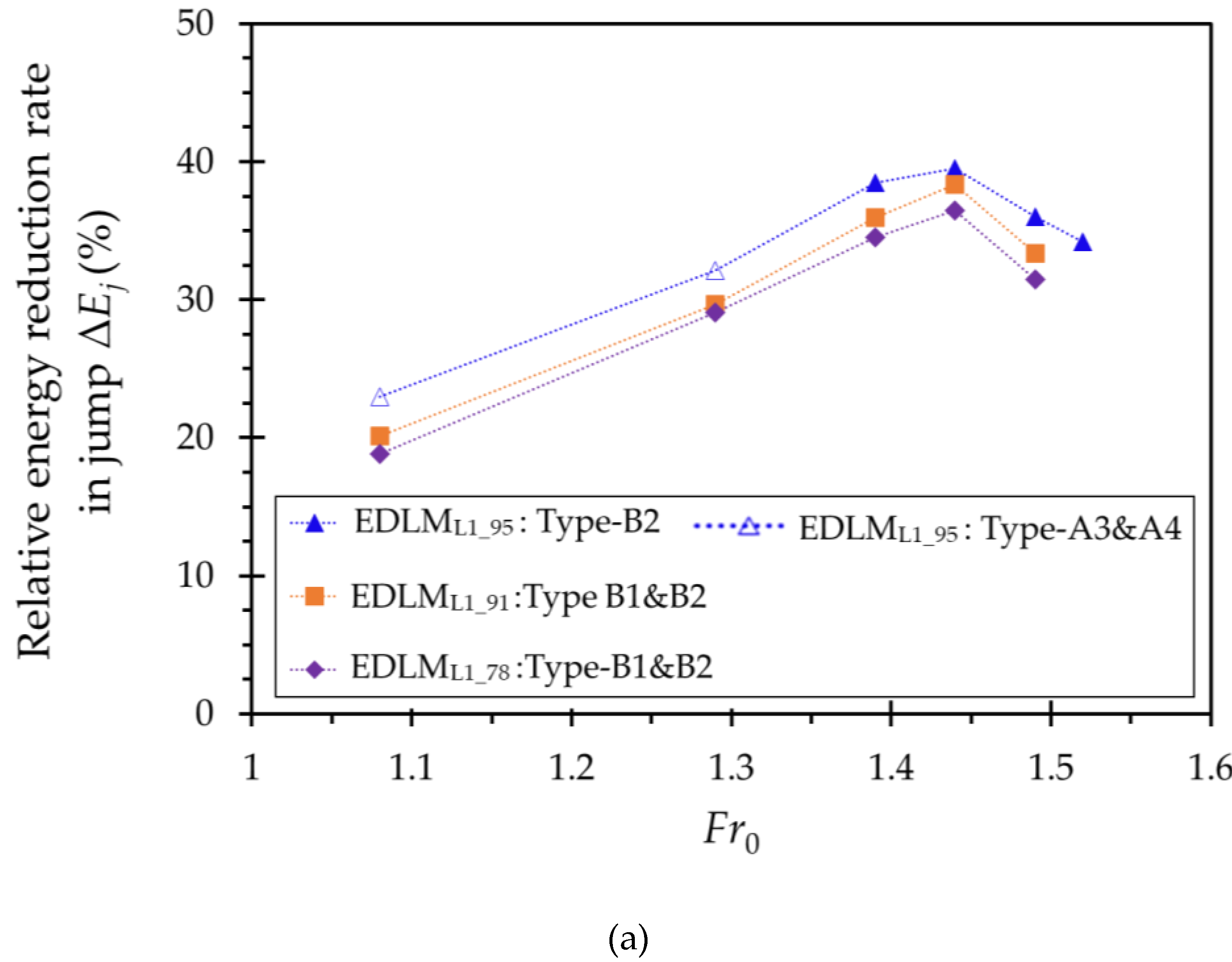


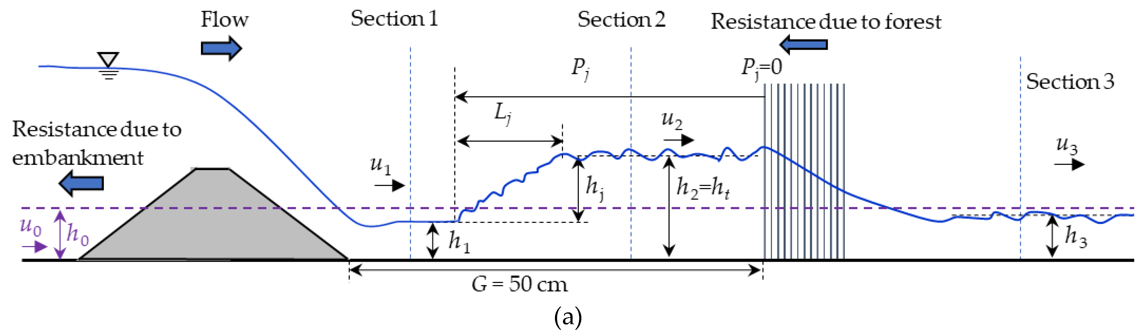
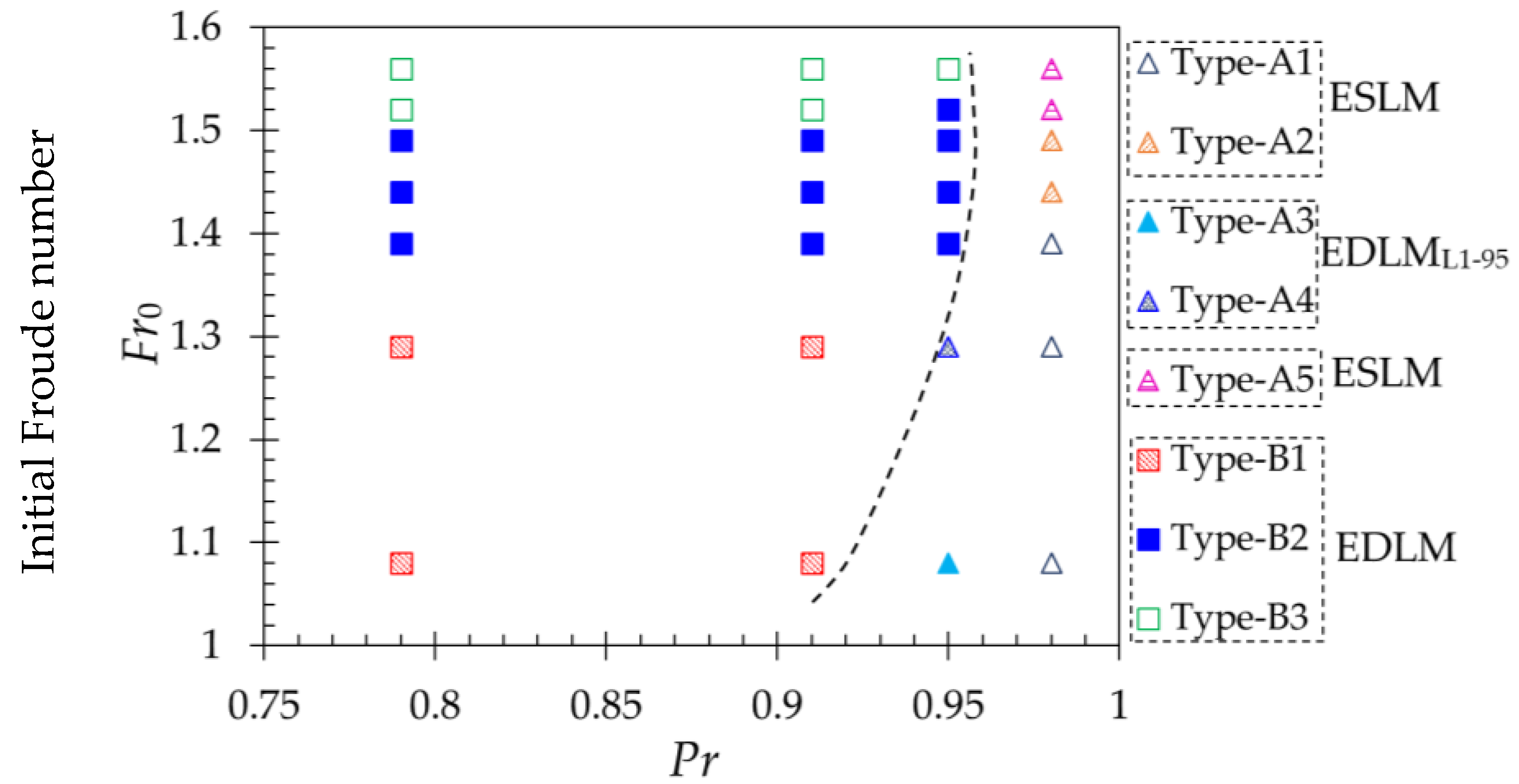
Table 1.
Summary of the experimental conditions (meaning of symbols and definitions appear in the Figure 1 and in text of the Section 2.1.1 and Section 2.1.2).
Table 1.
Summary of the experimental conditions (meaning of symbols and definitions appear in the Figure 1 and in text of the Section 2.1.1 and Section 2.1.2).
| Exp. Case | Initial Froude Number (Fr0) | Ds (cm) | Dt (cm) | Ss (cm) | St (cm) | d (cm) | WF (cm) | Porosity (Pr) of L1 % | Porosity (Pr) of L2 % |
|---|---|---|---|---|---|---|---|---|---|
| EMN | 1.08,1.29,1.39,1.44, 1.49,1.52,1.56 | - | - | - | - | - | - | - | - |
| ESLM | 1.08,1.29,1.39,1.44, 1.49,1.52,1.5 | - | 2.5 | - | 0.85 | 0.4 | 24.27 | - | 98 |
| EDLML1_95 | 1.08,1.29,1.39,1.44, 1.49,1.52,1.56 | 1.25 | 2.5 | 0.85 | 0.85 | 0.4 | 24.27 | 95 | 98 |
| EDLML1_91 | 1.08,1.29,1.39,1.44, 1.49,1.52,1.56 | 1.25 | 2.5 | 0.225 | 0.85 | 0.4 | 24.27 | 91 | 98 |
| EDLML1_78 | 1.08,1.29,1.39,1.44, 1.49,1.52,1.56 | 0.83 | 2.5 | 0.017 | 0.85 | 0.4 | 24.27 | 78 | 98 |
Note: EMN: embankment model with no forest; ESLM: embankment with single-layer (only emergent forest having 98% porosity) forest model; EDLM: embankment with double-layer (L1 + L2; L1: submerged; L2: emergent) forest model; the subscripts L1_95, L1_91, and L1_78 represent the porosities of L1 (95%, 91%, and 78%, respectively).
Table 2.
Flow condition in the defense system and hydraulic jump position on the embankment slope.
| Result | Exp. Cases | Fr0 | ||||||
|---|---|---|---|---|---|---|---|---|
| Fr2 | 1.08 | 1.29 | 1.39 | 1.44 | 1.49 | 1.52 | 1.56 | |
| EMN | 2.92 | 3.24 | 3.35 | 3.52 | 3.59 | 3.67 | 3.75 | |
| ESLM | 2.73 | 3.23 | 3.28 | 3.10 | 2.67 | 1.04 | 0.70 | |
| EDLML1_95 | 0.98 | 0.91 | 0.54 | 0.54 | 0.58 | 0.54 | 0.53 | |
| EDLML1_91 | 0.20 | 0.25 | 0.31 | 0.35 | 0.40 | 0.42 | 0.42 | |
| EDLML1_78 | 0.12 | 0.18 | 0.23 | 0.26 | 0.32 | 0.35 | 0.35 | |
| lj/HE | EMN | - | - | - | - | - | - | - |
| ESLM | - | - | - | - | - | - | - | |
| EDLML1_95 | - | - | - | 0.142 | 0.228 | 0.486 | 0.689 | |
| EDLML1_91 | 0.331 | 0.452 | 0.408 | 0.525 | 0.559 | 0.897 | 0.897 | |
| EDLML1_78 | 0.609 | 0.722 | 0.753 | 0.897 | 1.051 | 1.217 | 1.221 | |
Where, Fr2: average Froude number in the model zone (~300 cm downstream from the toe of the EM); lj: horizontal distance of the jump on embankment slope; and HE: embankment height.
© 2019 by the authors. Licensee MDPI, Basel, Switzerland. This article is an open access article distributed under the terms and conditions of the Creative Commons Attribution (CC BY) license (http://creativecommons.org/licenses/by/4.0/).
Share and Cite
MDPI and ACS Style
Ali Hasan Muhammad, R.; Tanaka, N. Energy Reduction of a Tsunami Current through a Hybrid Defense System Comprising a Sea Embankment Followed by a Coastal Forest. Geosciences 2019, 9, 247. https://doi.org/10.3390/geosciences9060247
AMA Style
Ali Hasan Muhammad R, Tanaka N. Energy Reduction of a Tsunami Current through a Hybrid Defense System Comprising a Sea Embankment Followed by a Coastal Forest. Geosciences. 2019; 9(6):247. https://doi.org/10.3390/geosciences9060247
Chicago/Turabian StyleAli Hasan Muhammad, Rashedunnabi, and Norio Tanaka. 2019. "Energy Reduction of a Tsunami Current through a Hybrid Defense System Comprising a Sea Embankment Followed by a Coastal Forest" Geosciences 9, no. 6: 247. https://doi.org/10.3390/geosciences9060247
Note that from the first issue of 2016, this journal uses article numbers instead of page numbers. See further details here.