Desiccation Cracking Behavior of MICP-Treated Bentonite
by
 , ,
, ,
Mark Vail
1, 
Cheng Zhu
1,*,
Chao-Sheng Tang
2,
Luke Anderson
1,
Michael Moroski
1 and
Melissa Tabada Montalbo-Lomboy
3 1
Department of Civil and Environmental Engineering, Rowan University, Stratford, NJ 08028, USA
2
School of Earth Sciences and Engineering, Nanjing University, Nanjing 210008, China
3
Department of Experiential Engineering Education, Rowan University, Stratford, NJ 08028, USA
*
Author to whom correspondence should be addressed.
Geosciences 2019, 9(9), 385; https://doi.org/10.3390/geosciences9090385
Submission received: 14 June 2019
/
Revised: 26 August 2019
/
Accepted: 28 August 2019
/
Published: 2 September 2019
(This article belongs to the Special Issue Behavior of Expansive Soils and its Shrinkage Cracking)
Abstract
:This study aims to characterize the effect of microbial-induced calcite precipitation (MICP) on the desiccation cracking behaviors of compacted calcium bentonite soils. We prepare six groups of samples by mixing bentonites with deionized water, pure bacteria solution, pure cementation solution, and mixed bacteria and cementation solutions at three different percentages. We use an image processing tool to characterize the soil desiccation cracking patterns. Experimental results reveal the influences of fluid type and mixture percentage on the crack evolution and volumetric deformation of bentonite soils. MICP reactions effectively delay the crack initiation and remediate desiccation cracking, as reflected by the decreased geometrical descriptors of the crack pattern such as surface crack ratio. The mixture containing 50% bacteria and 50% cementation solutions maximizes the MICP treatment and works most effectively in lowering the soil cracking potential. This study provides new insights into the desiccation cracking of expansive clayey soils and shows the potential of MICP applications in the crack remediation.
1. Introduction
Geological waste disposal is a globally preferred method focusing on the storage of high-level radioactive waste. Municipal waste landfills remain the most common method of waste treatment worldwide. To ensure the long-term isolation of these geostorage systems, bentonite has been a favorable choice for buffering and backfilling because of its low permeability, high swelling, and high radionuclide retardation capabilities [1,2]. Under drying or heated environment, soil moisture content decreases and total volume shrinks. The resulting progressive formation of desiccation cracks imposes substantial negative impacts on the mechanical and hydraulic behaviors of clayey soils. These cracks undermine the mechanical integrity of the soil structure and cause considerable weakening in soil strength [3,4]. The extensive crack network formed by crack propagation and coalescence provides the dominant conductive pathways for fluid migration, resulting in an increase in the hydraulic conductivity of clayey soils by several orders of magnitude [5,6], which is critical to the isolation functionality of the geostorage system [7]. The degradation of clayey soil properties due to the presence of desiccation cracks under climate changes is responsible for many other geohazards, such as slope failure [8], embankment failure [9], and foundation and dam failure [10].
Research efforts have been dedicated to the development of soil improvement techniques for the remediation of desiccation cracking. Classical methods include the mechanical and physical improvement by compaction control, surcharge loading, or soil replacement, which are usually associated with high labor, high cost, and poor long-term serviceability [11]. Chemical agents such as cement and lime have been used to reduce the shrinkage potential and suppress the crack development in soils [12,13]. However, lime or cement additives did not completely suppress the soil desiccation cracking when the initial water content was high, and more importantly, might harm plant growth and cause irreversible environmental concerns [14]. The addition of fiber reinforcement has been adopted by a number of researchers in the past few decades (e.g., [15,16]). Research results reveal that fiber inclusions significantly reduce the amount of desiccation cracks in clayey soils. However, it remains challenging to minimize the agglomeration of fiber materials during mixing, especially at field scales [17]. These issues contribute to the necessity to develop a novel technology for soil crack remediation.
Microbial-induced calcite precipitation (MICP) has emerged in recent years as a potential solution for soil improvement. As a natural biological process, MICP is environment-friendly and low-maintenance based [18,19,20]. The fundamental mechanism of MICP can be characterized by the following equations, corresponding to two steps, respectively: (1) urea is hydrolyzed by microbial urease to form ammonium and carbonate ions; (2) the free calcium ions will react with the previously produced carbonate ions to generate calcite precipitations.
Typical geotechnical applications of MICP include the cementation of sands to enhance bearing capacity and liquefaction resistance [18], soil erosion control [21], cracking healing in concrete and masonry [22], and remediation of radionuclide- and metal-contaminated soil [23]. So far, most research has focused on sand, whereas few studies have been reported on clayey soils. The main limiting factor lies in the small pore-throat size among clay soil particles that restrain the bacteria from passing freely [24]. Cheng and Shahin [25] used clayey sand with up to 20% clay content and assessed three MICP treatment methods including injection, premixing, and diffusion. Cardoso et al. [26] carried out oedometer and Brazilian splitting tests to characterize the biocementation effect on clayey sand and highlighted the importance of chemical effects originated from the clay fraction on soil behavior. Li et al. [27] blended fly ash at different concentrations into the MICP-treated expansive soil and showed that biocement and fly ash contributed jointly to the soil improvement. Guo et al. [28] demonstrated the potential benefit of MICP in remediating bentonite’s desiccation cracking in the lab scale, and compared the cracking pattern based on visual observations. Most abovementioned studies only focus on the influences of MICP on the physical and mechanical properties of clayey soils, whereas there is still lack of knowledge in the quantitative analysis of the desiccation cracking behaviors of MICP-treated soils.
This study aims to characterize the effect of MICP on the remediation of desiccation cracking in compacted bentonite soils. To overcome the difficulty of fluid migration in low-permeability bentonite, we mixed bentonite with different percentages of bacteria and cementation solutions and prepared six types of soil samples. Other stabilizing agents are not considered in this study to eliminate potential influences on the results. Desiccation drying tests were carried out, with cracking morphology captured by a high-resolution camera and quantified through image processing. The structure of this paper is organized as follows. Section 2 details the sample preparation, testing procedure, and image analysis steps adopted in this study. Section 3 presents experimental observations of desiccation crack patterns and quantitative image analysis results. Section 4 discusses the impacts of solution type on soil cracking and comment on the existing work. Section 5 summarizes the major findings obtained from this study.
2. Materials and Methods
2.1. Soil
The calcium bentonite clay provided by Bulk Apothecary Inc. is tested in this study. We performed sieve analysis and hydrometer analysis for grain size analysis, and Atterberg limit tests to determine the soil plasticity. Table 1 summarizes the physical properties of the original soil. According to the Unified Soil Classification System (USCS) [29], this soil can be classified as clay of high plasticity (CH). According to the analysis result provided by Bulk Apothecary Inc., its clay fraction is dominated by montmorillonite and soluble calcium amount is 21.2 meq.
2.2. Bacteria and Cementation Solution
In this study, we used a urease-active strain Sporosarcina pasteurii (ATCC 11859) for the MICP treatment because of its well-defined urease-synthesis behavior and strong biological activity under alkaline environment [30]. To initialize the growth of bacterial colonies, we rehydrated pure bacterium strain in the solid ammonium yeast extract (NH4-YE) medium for 24 h followed by low-temperature storage in Petri dishes at 4 ℃. High bacterial concentration could be reached through the incubation of bacteria in the liquid bacterial growth medium. We prepared the growth medium by mixing 20 g/L yeast extract, 10 g/L ammonium sulfate, 15.73 g/L Tris base. We sterilized each ingredient of the medium in an autoclave at 121℃ for 20 min before mixing. After inoculation of the bacteria from the solid NH4-YE medium into the liquid bacterial growth media, we started the incubation process by shaking the flask inside an incubator at a rotation speed of 200 rpm under a constant temperature of 30 ℃. The optical OD600 value was adopted as an indicator of the bacteria concentration, measured using an ultraviolet spectrophotometer at 600 nm wavelength. Continual measurements indicated that OD600 increased with time and reached an ultimate range of 1.724 absorbance after 48 h (Figure 1a). To further assess the bacteria activity based on the concentration of ammonium produced from urea, we resorted to the measurement of the electrical conductivity of the bacteria solution [31]. As the bacteria became more active and helped produce more ammonium, the electrical resistivity of bacteria solution increased, and gradually stabilized after approximately 24 h (Figure 1b). Therefore, to ensure maximum activity, the bacteria used in this study were incubated for 24–48 h.
2.3. Sample Preparation
The soil was air-dried, crushed, and passed through a no. 200 sieve. To investigate the influences of pore fluids on soil cracking behavior, different specimens with varying fluid compositions were prepared. Each bentonite mixture has a moisture content of 100%, which corresponds to the following six types of pore fluids: (a) 100% pure deionized water (considered as control mixture, denoted as sample W); (b) 100% bacteria solution (denoted as sample B); (c) 100% cementation solution (denoted as sample C); (d) 25% bacteria solution and 75% cementation solution (denoted as sample 25B75C); (e) 50% bacteria solution and 50% cementation solution (denoted as sample 50B50C); and (f) 75% bacteria solution and 25% cementation solution (denoted as sample 75B25C). The mixture of bacteria and cementations solutions is denoted as solution BC in this manuscript. MICP-treated samples refer to sample types (d), (e), and (f). As the initial water content was less than LL, the desiccation cracking of bentonite started from an unsaturated state, which aims to avoid excessive cracking. 100% fluids were added into the dry bentonite for mixing. Each mixing process continued for 10 min until the mixture reached a homogeneous state. For each mixture type, three parallel samples were made to validate the experimental repeatability. Moist soils were molded into the 50 mm diameter Petri dishes (inner depth = 6.35 mm) and filled the volume completely. In this study, the soil–dish interface was cleaned and dried, before the placement of the slurry soil specimen. Literature reviews indicate that using different materials (e.g., glass, wood) as the soil mold influences the size of the desiccated soil clods [34]. Smooth contact surfaces result in smaller width and spacing of the cracking [35], whereas rough interfaces lead to larger extent of cracking and wider crack width distributions [36]. Although the interface roughness was not characterized in this study, we examined the repeatability of the test by comparing results obtained from three parallel samples.
2.4. Testing Procedure
All soil samples underwent the same desiccation process, with each mixture placed in a Petri dish and exposed to relatively stable room conditions at a temperature of 30 ± 1 ℃ and a relative humidity of 50% ± 5% for drying. Figure 2 demonstrates the schematic view of the experimental setup. The Petri dish containing the bentonite sample was placed on a scale, to continuously monitor the temporal change of soil weight. Under LED light conditions, a high-resolution digital camera mounted on top captured the evolving desiccation crack patterns in bentonite samples for subsequent image processing and quantitative analyses. To further characterize soil microstructural changes, we made observations through the scanning electron microscopy (SEM) on the completely dried samples.
2.5. Image Processing and Quantitative Analysis
To quantitatively compare the effects of various fluids on the soil desiccation process, an image processing software “Crack Image Analysis System” (CIAS) developed previously [37] was used here. As shown in Figure 3, the image processing comprised three major steps. First, the original color image showing crack patterns (Figure 3a) was converted into a grey-level image (Figure 3b). Then, by applying the binarization operation using a simple gray threshold, we were able to distinguish cracks from soil clods through their sufficiently high contrasts (Figure 3c). At last, after the removal of noises in the binary image through a filter operation (Figure 3d), CIAS automatically outlined the skeleton of crack networks (Figure 3e). The final segmented crack network (Figure 3f) was used to determine the following geometrical parameters: (1) surface crack ratio , referring to the ratio between the crack area and the total surface area of the soil sample; (2) average width of cracks , determined by calculating the shortest distance from a randomly chosen point on one boundary to the crack’s opposite boundary; (3) total length of cracks , determined by calculating the trace length of the medial axis of crack segment, reflected as the skeleton in Figure 3f; (4) crack segment number , indicating the total number of cracks after segmentation; and (5) average crack length , calculated as the ratio between total crack length and crack segment number (i.e., ). More details on the crack pattern descriptors are available in [37].
To further analyze the distribution features of the crack pattern, we calculated the density function of two crack geometry descriptors, including crack area and crack width . Take crack width for instance, the density function of crack width is a density of crack width corresponds to value and defined as (Tang et al., 2008)
in which is the total number of crack segments, is the number of crack segments whose width ranges between . The fraction of the crack width in the range of and is given by . If the crack width in a given crack pattern covers from length to , we have
This means that the number of crack segments whose value fall into the interval [a, b] equals the total number of crack segments, . We adopted the concept of the most probably value (MPV) of crack width, corresponding the width when the maximum value of is achieved [37]. Therefore, the probability of crack width near MPV is maximal during cracking. Probability distribution and MPV values are determined for crack area in a similar way.
3. Results
3.1. Experimental Observation of Desiccation Cracks
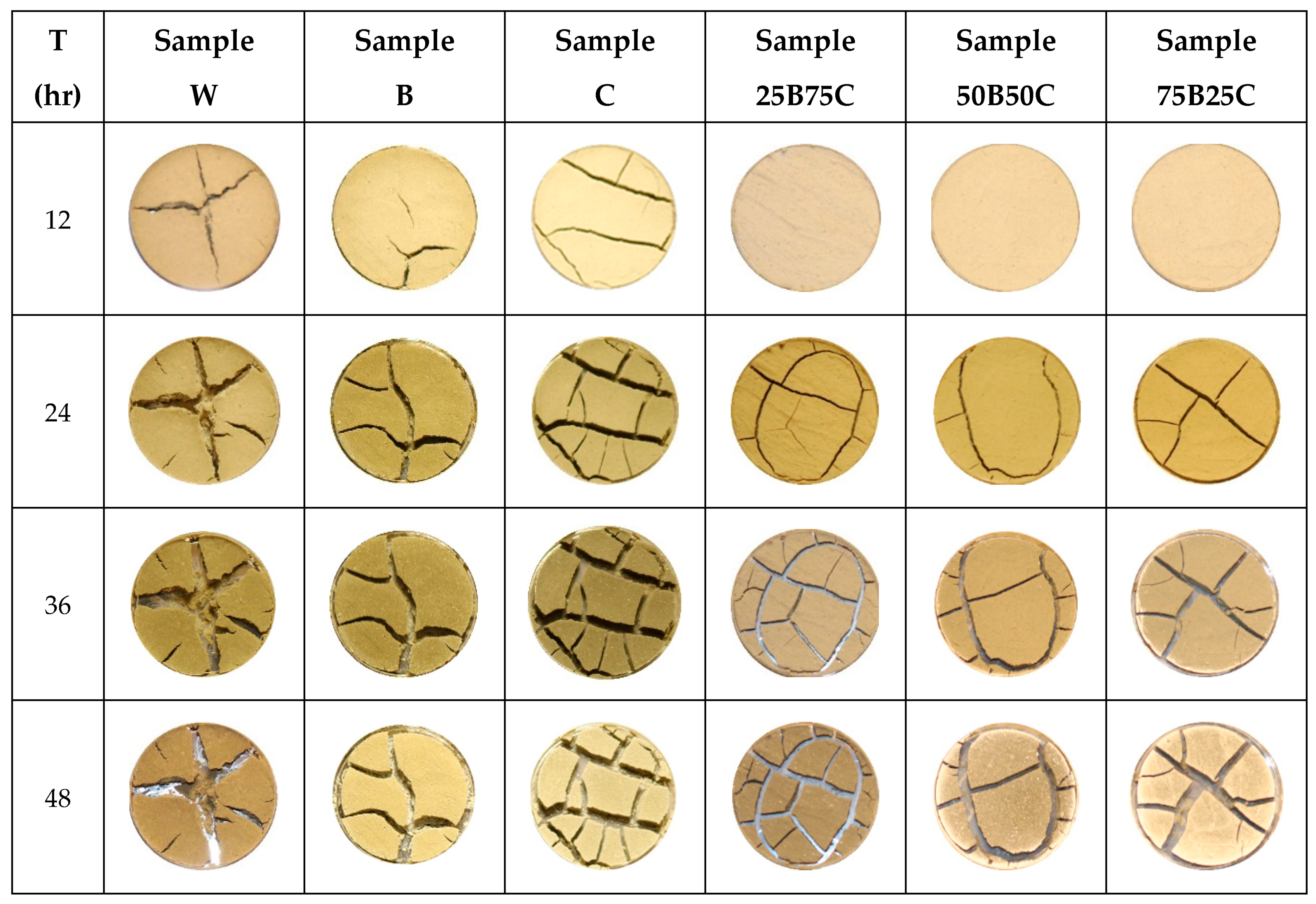
Figure 4 presents desiccation cracks captured at regular time intervals (12, 24, 36, and 48 h) for all six types of samples. For each mixing type, three parallel samples give comparable crack pattern results, verified by the subsequent image analysis. This proves that using different dishes with cleaned soil–dish interfaces has minor influences on the desiccation cracking results in this study. All samples experienced extensive cracking, with soil body split into separate clods by crack segments. During the drying process, we observed the process of crack initiation, propagation, coalescence, and intersection, leading to the formation of a complicated crack network throughout the soil sample. Cracks initiate from the weaker regions such as natural pores in the soil [38], propagate under the driving force of capillary suction, and bifurcate from primary into secondary crack branches. Experimental observations indicate that crack patterns changed most significantly during the rapid decrease of moisture content within 12–36 h. After 48 h, crack patterns remain unchanged while the water content stopped decreasing. The post-evolutions of crack patterns are mostly the broadening of crack width without generating any new crack branches.
Due to the effect of mixing fluids, six types of samples exhibit different cracking morphologies. Comparing these samples, after 12 h, considerable desiccation cracks were observed in samples W, B, and C, whereas MICP-treated samples remain intact (row ‘12-hr’ in Figure 4). This highlights the effect of MICP in delaying soil cracking and enhancing the soil strength. At 24 h, primary cracks, secondary cracks, and the separation between soil and Petri-dish boundary become apparent. Secondary cracks initiate from a primary crack or the circumferential boundary of the specimen (row ‘24-hr’ in Figure 4). The widths of primary cracks in samples W, B, and C are much larger than those of MICP-treated samples. As water content decreases, the growth of new secondary cracks continues, especially in MICP-treated samples. In all samples, crack width increases significantly. As the soil layer thickness is 0.635 cm, at the end of 36 h, most primary cracks have propagated to the bottom of the Petri dishes, as reflected by the visible dish bottom (row ‘36-hr’ in Figure 4). In the following 12 h, crack widths continue to increase whereas crack patterns stayed almost unchanged (row ‘48-hr’ in Figure 4). It is interesting to note that, in comparison to sample W, bentonite samples treated with MICP exhibit certain extent of color change on soil surface from yellow to white (row ’48-hr’). This color change implies the precipitation of calcium carbonate (CaCO3) film on soil surface resulting from the bio-cementation process. Although visual observations provide a qualitative view of the evolving crack pattern, the changes in crack width and crack length are difficult to quantify, requiring further image analysis of the crack pattern.
3.2. Quantitative Analysis of Crack Patterns
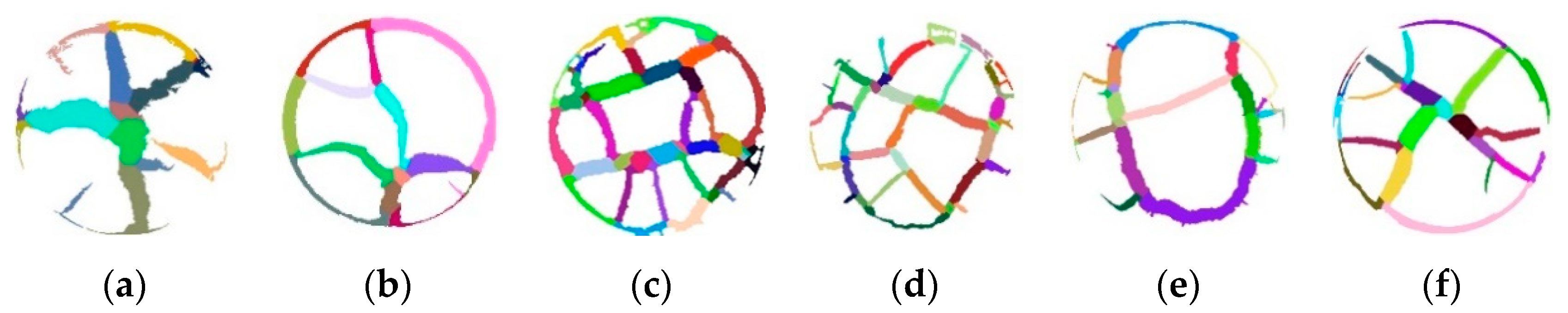
To quantify the evolving characteristics of crack patterns, we performed image analysis on all final crack patterns at the end of 48 h. Crack segments generated from the image processing of the final crack pattern at 48 h are shown in Figure 5, with different colors representing different crack segments. The final crack pattern consists of both shrinkage cracks and the circumferential edge-soil separations. Based on these crack segments, we determined five geometrical parameters as defined in Section 2.5, including surface crack ratio, average width of cracks, total length of cracks, crack segment number, and average crack length.
As shown in Table 2, mixing MICP solution with bentonite effectively mitigates soil desiccation cracking and reduces the surface crack ratio by up to 23%, from the maximum value of 29.2% (sample W) to the minimum value of 22.6% (sample 50B50C). Sample 50B50C gives slightly lower surface crack ratio than other two MICP-treated samples, highlighting the importance of solution fraction ratio in optimizing the biocementation effect. Over supply of bacteria or cementation solutions does not necessarily increase the amount of calcite precipitations. Samples W and C give comparable surface crack ratios, whereas sample B gives a much lower surface crack ratio.
In terms of average crack width, sample W gives the largest value, 65% higher than that of sample 25B75C. Except sample W and sample C, other samples share comparable smaller average crack width at 0.17–0.18 cm. Due to the much larger crack width, total crack length of sample W is the smallest. Among MICP-treated samples, sample 50B50C gives the smallest total crack length.
The correlation between surface crack ratio and crack number is not clear, which requires further investigations in the future. In this study, sample C presents the highest number of cracks, whereas sample W gives the lowest. Due to the presence of high crack segment number, samples C and 25B75C give the lower average crack length. On the contrary, sample W with the minimum crack segment number has the largest average crack length of 1.46 cm.
4. Discussion
4.1. Effect of Solution Type on Water Evaporation
Desiccation cracking process occurs after certain extent of water loss. Understanding the water evaporation process and identify the critical water content is key to the study of cracking process. In this study, critical water content refers to the water content when first desiccation crack initiates. We found that, in all samples, the circumferential soil–dish separation occurred later than desiccation cracks. Comparing the desiccation time at the onset of surface cracking, the formation of cracks was first observed after 2.5 h in sample W, followed by 4.5–5 h in samples B and C, and then more than 16 h in samples treated with MICP (Table 3). In samples B and C, the presence of nutrients in bacteria and cementation solutions decreases the thickness of the double diffusion layer (DDL) of clay minerals and enhances the inter-particle bonding [39,40]. Ammonium compounds are also effective ion exchangers within the clay lattice and thus can reduce clay activity [41]. These effects jointly contribute to the delayed crack initiation observed in modified soil samples. The much longer initiation time observed in samples treated with MICP further validates the effects of MICP in strengthening the soil body and lowering the cracking potential. The critical water content at crack initiation could be obtained based on the change of the soil total weight. When cracks initiated, sample W still has a high water content at 93.5%, in comparison to the initial water content of 100%. Other samples exhibit lower water content levels at the onset of desiccation cracking, thus correspond to more water loss. The general trend is that when cracks first appeared, larger total weight change was recorded in MICP-treated samples, implying a larger amount of water evaporation than other samples. Under drying, water evaporation results in matrix suction and soil volume shrinkage, forming a tensile stress field. Cracks initiate when the tensile stress exceeds the tensile strength of the soil. Samples treated with MICP gain higher strengths as a result of the biocementation effect, which thus requires a larger driving force associated with more water evaporation to satisfy the cracking criterion.
It should be noted that desiccation cracks may initiate from both the surface and inner body of the soil specimen. Morris et al. [38] concluded that suction stress developed in the soil body during drying created micro-cracks among particles and further evolve into the macroscopic crack network. Weinberger [42] analyzed the desiccation cracking of marine sediments and observed that cracks developed from the bottom and propagates to the top. Other researchers also found that desiccation cracks initiated at the weak points on the soil surface, mainly geometrically convex or concave areas, resulting from the faster surface water loss and the development of local stress concentrations [43]. Because of the natural heterogeneity of soil, the precise prediction of crack initiation location remains challenging. Past research results indicate that cracking extent decreases with increasing soil thickness [38]. In this study, the specimen has a thin layer of 6.35 mm, which allows a relatively fast propagation of desiccation cracks from inner soil body to the surface and ensures the reliability of using camera to characterize crack initiation and evolutions.
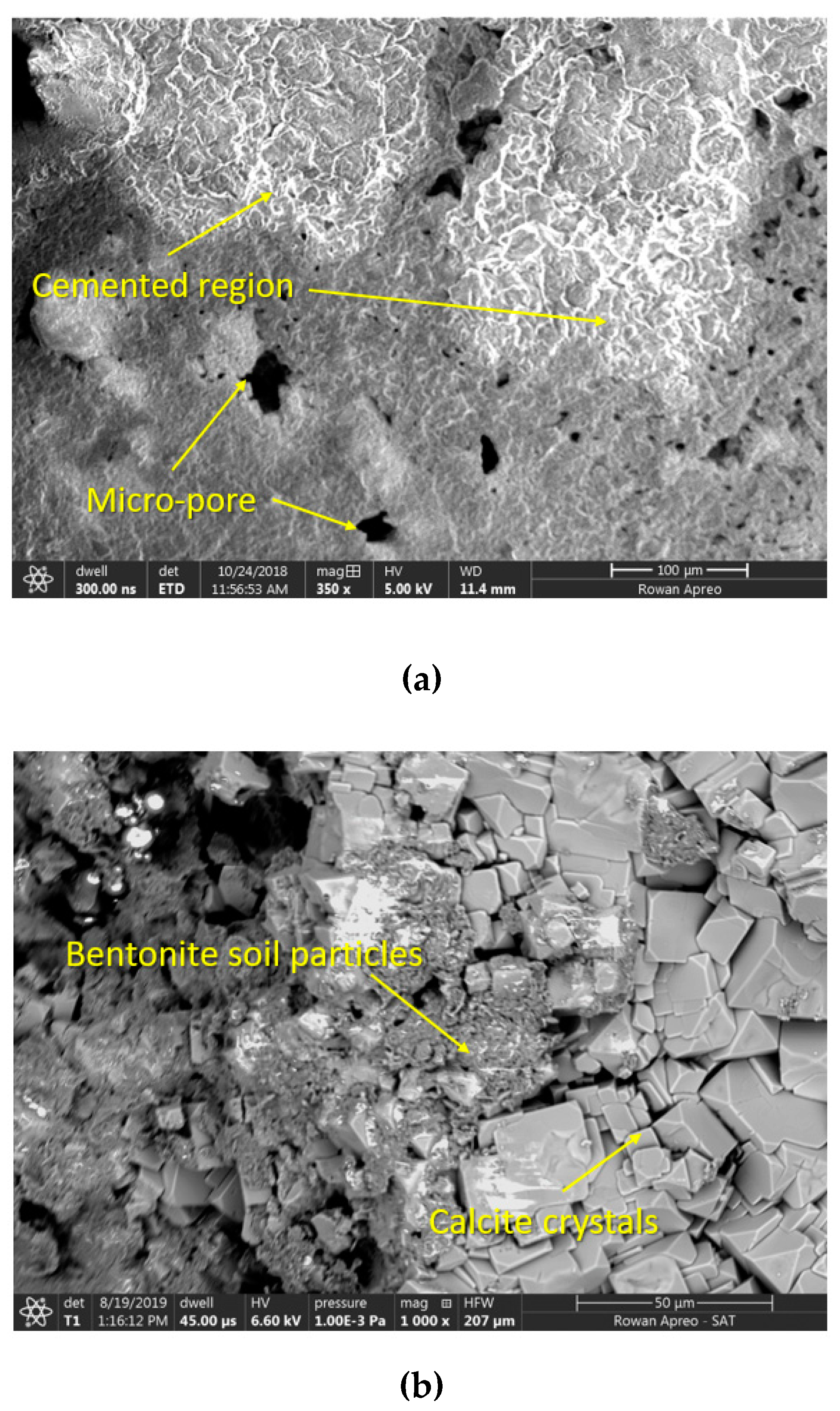
In general, the evaporation process can be decomposed into three stages [44]: (1) constant rate stage; (2) falling rate stage; and (3) residual rate stage. At the constant rate stage, the soil remains saturated and the evaporation rate is dominated by ambient factors. Desiccation cracks start to develop in the constant rate stage when the soil remains saturated. With ensuing drying, when air starts to replace water in the pores and soil changes from saturated to unsaturated state, the evaporation process transits to the falling rate stage. Therefore, the transition point of the evaporation curve corresponds to the air-entry state of soil. Given the soil tested here had a water content of 100%, less than the liquid limit, only falling rate and residual rate stages should be observed. However, in this study, these two phases were not observed in MICP-treated samples. This can be attributed to two factors, the hydrolysis of urea and the bio-mediated soil reinforcement. According to Equation (1), water is involved during the hydrolysis reaction, which considerably lowers the water amount that is available for evaporation under drying. Therefore, at the end of desiccation test, the percentage of water loss, defined as the ratio between the amount of water loss and the original water amount, is 50%, 60%, and 58% for samples 25B75C, 50B50C, and 75B25C, respectively. On the other hand, the precipitated calcite in Equation (2) acting as a bonding agent to bentonite clay particles delays and reduces the soil cracking process. The presence of less cracks decreases the soil surface area that is in contact with atmosphere, contributing to the slow down and reduction of the moisture loss. SEM observations validate this phenomenon. As shown in Figure 6a, in sample 75B25C, the white region corresponds to the area where biocementation occurred, whereas grey regions represent less-cemented areas. Micro-pores of different sizes mostly exist in the less-cemented areas. Such pores could be caused by the evaporation of water and the continued volumetric shrinkage of soil body. Magnified view revealed the precipitation of calcite crystals among the bentonite soil body. These crystals provide effective bridging within the soil particles, which is consistent with observations made by other researchers [20,32]. SEM observations highlight the microstructural heterogeneity under the coupled effects of biocementation and water evaporation.
To further validate the existence of calcite precipitations in MICP-treated bentonite soil samples, we adopt the acid digestion method [45] to quantify the amount of calcite in sample 50B50C. 15 g mixtures were collected from the desiccated soil sample, crushed into fragments, immersed into the 0.1 mol/L HCl solution to reach the complete dissolution of carbonate, and oven-dried. The difference in dried mass before and after this process gives the mass of calcium carbonate. Experimental measurement indicates that the calcium carbonate content in sample 50B50C is approximately 13.5%. Future study will use this method to quantitatively compare the amount of calcite in soils treated with different solutions.
At the end of desiccation test, samples 50B50C and 75B25C experienced 60% and 58% loss of their initial fluid contents respectively, higher than 50% fluid loss in sample 25B75C. The reduction in water is partially caused by the hydrolysis reaction during the biocementation process. Therefore, increasing extent of biocementation corresponds to more water loss and more calcite precipitations. Zhao et al. [46] showed that, the calcite content and the sandy soil strength increased with increasing bacteria, whereas more cementation media has limited effects in enhancing MICP results. This explains why samples 50B50C and 75B25C showed smaller surface crack ratios (Table 2) and higher water losses than sample 25B75C at the end of desiccation test.
4.2. Effect of Solution Type on Crack Pattern
To study the effect of soil type on desiccation crack pattern, we carried out the quantitative analysis of crack geometrical parameters. The probability density functions of crack parameters including crack area and crack width, as described in Section 2.5, are determined to compare the solution effect on final crack pattern.
The probability distributions of crack areas can be approximated by the power law distribution, with much higher probability value obtained for smaller cracks and very small probability value for larger cracks (Figure 7). The area of most cracks in all samples is below 0.2 cm2, whereas more than 40% of the cracks in sample W have an area larger than 0.3 cm2. The presence of larger crack areas (Figure 7) and wider crack widths (Figure 8) in sample W can be attributed to two factors. First, in comparison with other samples, cracking initiates first in sample W, which corresponds to an earlier and more mature development of crack networks. Higher cracking extent increases the soil–air contact areas, which further contributes to more water evaporation and continued cracking. Second, as desiccation time evolves, other samples treated with bacteria, cementation or MICP solutions were experiencing both cracking and time-dependent cementation of the sample. Although the MICP process could not be initiated in samples B and C, large cracks are not visible. The surface crack ratios of samples W, B, and C (Table 2) are not able to reveal the distribution features. Although samples W and C share similar value of surface crack ratio, their probability distributions vary significantly. In general, when cementation solution is added to the clayey soil, Ca2+ ions replace monovalent, metallic ions surrounding the clay particles. Clay particles are surrounded by a diffuse hydrous double layer which is modified by the ion exchange of calcium. This alters the density of the electrical charge around the clay particles, which leads to the enhanced attraction and the formation of flocs, and eventually changes the soil texture [47,48]. However, in our study, cementation solution has little effect on the cracking of sample C, which is mostly because the bentonite soil is rich in calcium and has formed a relatively stable soil structure. If another type of clayey soil such as sodium bentonite was used, the addition of cementation solution will show a much stronger cementation effect [49]. In sample B mixed with bacteria solution, numerous microbes fill up the inter-particle pores and adhere to the surface of soil particles, which may induce the formation of biofilms on soil particles and affect the physical properties of soil [50].
Among three MICP-treated samples, sample 50B50C has the highest probability distribution of small cracks with area less than 0.1 cm2 (Figure 7), validating the best cementation effect in this sample. Although sample 25B75C shows a larger surface crack ratio than sample 75B25C, majority of its cracks are limited to 0–0.2 cm2. Comparatively, sample 75B25C has less small cracks and has a broader range of crack area. The most probable values (MPV) of samples B, 25B75C, 50B50C, and 75B25C are within the range of 0–0.1 cm2, while the MPV values of samples W and C are around 0.1–0.2 cm2.
Figure 8 shows the probability distribution plots of crack width, which is different from that of crack area. This is because larger cracks may have small widths but large lengths. While majority of the cracks in the MICP-treated samples belong to narrow cracks with width less than 0.2 cm, 50% of the cracks in sample W are larger than 0.25 cm wide. Sample W has a much broader range of crack widths, varying from 0 to 0.7 cm, than all other samples. Comparing all samples, cracks in sample B are more uniform, as demonstrated by the high probability value for both crack area (0–0.1 cm2) and crack width (0.1–0.2 cm). In this study, MPV for crack width is 0.1–0.2 cm for samples B, C, 25B75C, and 50B50C, and 0–0.1 cm for samples W and 75B25C. These probability distribution plots provide a better quantitative overview of the crack pattern.
4.3. Significance and Limitation of Current Work
Our research indicates that mixing MICP solutions with bentonite soils restrains the shrinkage cracking and reduces the crack geometric parameters, particularly surface crack ratio and average crack width. As introduced earlier, the variation of the crack geometry governs the hydraulic and mechanical properties of soil. In comparison to the control sample, MICP-treated bentonite is expected to possess an improved hydraulic conductivity and mechanical strength due to the bonding effect of CaCO3 produced in the MICP process. The improved structural integrity of MICP-treated bentonite is of great importance to the performance of geological storage systems. It should be noted that geoenvironmental applications discussed in the introduction generally use sodium bentonite, which has a larger liquid limit and plastic index and is about 10 times less permeable than calcium bentonite. If mixed with CaCl2 solutions, both types of bentonite soils have approximately the same liquid limit and plasticity index [51]. As a preliminary study, our main goal is to validate the applicability of MICP treatment in remediating desiccation cracks in clayey soils. Given the stronger ionic exchange capability of Ca2+, using calcium bentonite will minimize the influence of ionic exchanges on the soil double layer thickness. The influences of bentonite type on desiccation cracking results will be compared in future studies.
The MICP treatment presents a number of advantages over existing soil improvement techniques. Our study indicates that MICP treatment can delay the crack initiation and suppress the soil desiccation cracking significantly at high initial water content, because of the remarkable water stability of calcite mineral produced in the MICP process. For clayey soils with calcium contents, the MICP treatment effect can be optimized given the appropriate amount of bacteria and cementation solutions. As a natural biological process, the MICP is an more environment-friendly and energy efficiently solution for soil desiccation cracking remediation. Moreover, the residual urea in soil during MICP process can provide nutrients for plant growth.
This study has demonstrated the feasibility of using MICP to remediate desiccation cracking in small bentonite soil samples at lab scale. The premixing process limits this method to compacted bentonite soils, with potential applications in nuclear waste disposal. The bio-grouting and injection methods will be extremely challenging for bentonite due to its small pores and low permeability. Alternative approaches such as surface spraying of MICP solution may be a better solution. Due to the scale and boundary effects, lab results still show large deviations with field measurements. For instance, compared to the field tests reported by Li and Zhang [52], the crack length is shorter and crack density is higher in the small soil sample of current study. In addition, the crack distribution is more inhomogeneous in field tests, as the soil often contains coarse particles and structures, and has more complicated interactions with the varying atmosphere in field. In order to investigate the potential application of MICP for soil crack remediation in field, more in-situ tests will be needed. Furthermore, the influence of MICP on the crack depth is not considered and will be studied in the future work.
5. Conclusions
The formation of desiccation cracks in bentonite soils is detrimental to the long-term performance of engineered clay barriers in geological storage facilities. In this study, we investigated the potential of the MICP treatment in the remediation of desiccation cracks for compacted bentonite. Laboratory desiccation tests were conducted on bentonite samples mixed with deionized water, bacteria solution, cementation solution, or different percentages of bacteria and cementation solutions. Relying on imaging tools including camera and SEM, we carried out qualitative and quantitative analyses on soil cracking behaviors and reached the following conclusions:
(1) MICP significantly delays the initiation of desiccation cracks in bentonite soils. The formation of cracks was first observed in sample treated with water after 2.5 h of drying, followed by 4.5–5 h in samples treated with bacteria or cementation solutions, and then more than 16 h in samples treated with MICP.
(2) MICP-treated soil samples show less desiccation cracks, as reflected by the surface crack ratio and average crack width. Under the MICP process, the calcite crystal precipitations contributes primarily to the improved mechanical integrity of soil sample as well as desiccation cracking resistance. The sample treated with bacteria solution also gives less cracks as a result of the formation of biofilm around clay particles due to the presence of microbes. For calcium bentonite, cementation solution containing calcium chloride has negligible impacts on the remediation of soil cracking.
(3) The water evaporation in MICP-treated samples is governed by two factors including the hydrolysis of urea and the bio-mediated soil reinforcement. More water loss is needed in MICP-treated samples to generate larger suction stresses as the crack driving force. More bacteria or more cementation solution in the mixture may not necessarily reduce the water evaporation.
(4) The probability distributions of crack areas can be approximated by the power law distribution. The MPV of crack areas for samples B, 25B75C, 50B50C, and 75B25C are within the range of 0–0.1 cm2, while that of samples W and C are around 0.1–0.2 cm2. Most cracks in the MICP-treated samples are narrow with width less than 0.2 cm, whereas 50% of the cracks in sample W are larger than 0.25 cm wide. MPV for crack width is 0.1–0.2 cm for samples B, C, 25B75C, and 50B50C, and 0–0.1 cm for samples W and 75B25C.
This study validates the applicability of MICP treatment in reinforcing clayey soils for drying conditions. Bonding crystals produced from MICP enhances the soil strength and lowers the potential of desiccation cracking in clayey soils. Future study will focus on the application of multiple MICP treatments in clayey soils. The bio-stabilization of clayey soils explored in this study brings new insights into the remediation of soil erosion and cracking for various climate changes, which is key to the design and performance of sustainable geotechnical infrastructures.
Author Contributions
Conceptualization, C.Z. and C.-S.T.; Methodology, M.V., L.A., M.M., and M.T.M.-L.; Formal analysis, M.V., L.A., and M.M.; Resources, M.T.M.-L.; Writing—original draft preparation, C.Z. and M.V.; Writing—review and editing, C.Z., M.V. and C.-S.T.; Supervision, C.Z. and C.-S.T.
Funding
This research was funded by the Startup Fund and the Seed Fund of Rowan University.
Acknowledgments
This study is supported by the Startup Fund and the Seed Fund of Rowan University. The support of using SEM from Wei Xue in the Department of Mechanical Engineering at Rowan University is greatly appreciated.
Conflicts of Interest
The authors declare no conflict of interest.
References
- Pusch, R. Highly compacted sodium bentonite for isolating rock-deposited radioactive waste products. Nucl. Technol. 1979, 45, 153–157. [Google Scholar] [CrossRef]
- Villar, M.V.; Lloret, A. Influence of dry density and water content on the swelling of a compacted bentonite. Appl. Clay Sci. 2008, 39, 38–49. [Google Scholar] [CrossRef]
- Chertkov, V.Y.; Ravina, I. Tortuosity of crack networks in swelling clay soils. Soil Sci. Soc. Am. 1996, 63, 1523–1530. [Google Scholar] [CrossRef]
- Hallett, P.D.; Newson, T.A. Describing soil crack formation using elastic-plastic fracture mechanics. Eur. J. Soil Sci. 2005, 56, 31–38. [Google Scholar] [CrossRef]
- Boynton, S.S.; Daniel, D.E. Hydraulic Conductivity Tests on Compacted Clay. J. Geotech. Eng. 1985, 111, 465–478. [Google Scholar] [CrossRef]
- Albrecht, B.A.; Benson, C.H. Effect of Desiccation on Compacted Natural Clays. J. Geotech. Geoenviron. Eng. 2001, 127, 67–75. [Google Scholar] [CrossRef]
- Miller, C.J.; Mi, H.; Yesiller, N. Experimental analysis of desiccation crack propagation in clay liners. JAWRA J. Am. Water Resour. Assoc. 1998, 34, 677–686. [Google Scholar] [CrossRef]
- Alonso, E.; Gens, A.; Lloret, A.; Delahaye, C. Effect of rain infiltration on the stability of slopes. In Proceedings of the First International Conference on Unsaturated Soils, Paris, France, 6–8 September 1995. [Google Scholar]
- Groenevelt, P.; Grant, C. Analysis of soil shrinkage data. Soil Tillage Res. 2004, 79, 71–77. [Google Scholar] [CrossRef]
- Osinubi, K.J.; Nwaiwu, C.M.O. Desiccation-induced Shrinkage in Compacted Lateritic Soils. Geotech. Geol. Eng. 2008, 26, 603–611. [Google Scholar] [CrossRef]
- Steinberg, M.L. Geomembranes and the Control of Expansive Soils in Construction. In Proceedings of the Geosynthetics 1999, Specifying Geosynthetics and Developing Design Details, Boston, MA, USA, 28–30 April 1999. [Google Scholar]
- Leung, M.; Vipulanandan, C. Treating Contaminated, Cracked and Permeable Field Clay with Grouts. In Proceedings of the Specialty Conference on Geotechnical Practice in Waste Disposal, Geotechnical Special Publication. Ann Arbor, MI, USA, 13–15 June 1977; ASCE: Reston, VA, USA, 1995; pp. 829–843. [Google Scholar]
- Al-Taie, A.; Disfani, M.M.; Evans, R.; Arulrajah, A.; Horpibulsuk, S. Swell-shrink Cycles of Lime Stabilized Expansive Subgrade. Procedia Eng. 2016, 143, 615–622. [Google Scholar] [CrossRef] [Green Version]
- Omidi, G.H.; Prasad, T.V.; Thomas, J.C.; Brown, K.W. The influence of amendments on the volumetric shrinkage and integrity of compacted clay soils used in landfill liners. Water Air Soil Pollut. 1996, 86, 263–274. [Google Scholar] [CrossRef]
- Harianto, T.; Hayashi, S.; Du, Y.-J.; Suetsugu, D. Effects of Fiber Additives on the Desiccation Crack Behavior of the Compacted Akaboku Soil as A Material for Landfill Cover Barrier. Water Air Soil Pollut. 2008, 194, 141–149. [Google Scholar] [CrossRef]
- Tang, C.-S.; Shi, B.; Cui, Y.-J.; Liu, C.; Gu, K. Desiccation cracking behavior of polypropylene fiber–reinforced clayey soil. Can. Geotech. J. 2012, 49, 1088–1101. [Google Scholar] [CrossRef]
- Reddy, N.G.; Tahasildar, J.; Rao, B.H. Evaluating the influence of additives on swelling characteristics. Int. J. Geosynth. Ground Eng. 2015, 7, 2–13. [Google Scholar]
- DeJong, J.T.; Fritzges, M.B.; Nüsslein, K. Microbially Induced Cementation to Control Sand Response to Undrained Shear. J. Geotech. Geoenviron. Eng. 2006, 132, 1381–1392. [Google Scholar] [CrossRef]
- Ivanov, V.; Chu, J. Applications of microorganisms to geotechnical engineering for bioclogging and biocementation of soil in situ. Rev. Environ. Sci. Bio/Technol. 2008, 7, 139–153. [Google Scholar] [CrossRef]
- Soon, N.W.; Lee, L.M.; Khun, T.C.; Ling, H.S. Improvements in engineering properties of soils through microbial-induced calcite precipitation. KSCE J. Civ. Eng. 2013, 17, 718–728. [Google Scholar] [CrossRef]
- Jiang, N.J.; Soga, K.; Kuo, M. Microbially induced carbonate precipitation for seepage-induced internal erosion control in sand–clay mixtures. J. Geotech. Geoenviron. Eng. 2016, 143, 04016100. [Google Scholar] [CrossRef]
- Bang, S.S.; Lippert, J.J.; Yerra, U.; Mulukutla, S.; Ramakrishnan, V. Microbial calcite, a bio-based smart nanomaterial in concrete remediation. Int. J. Smart Nano Mater. 2010, 1, 28–39. [Google Scholar] [CrossRef]
- Fujita, Y.; Taylor, J.L.; Gresham, T.L.T.; Delwiche, M.E.; Colwell, F.S.; McLing, T.L.; Petzke, L.M.; Smith, R.W. Stimulation of microbial urea hydrolysis in groundwater to enhance calcite precipitation. Environ. Sci. Technol. 2008, 42, 3025–3032. [Google Scholar] [CrossRef]
- DeJong, J.T.; Mortensen, B.M.; Martinez, B.C.; Nelson, D.C. Bio-mediated soil improvement. Ecol. Eng. 2010, 36, 197–210. [Google Scholar] [CrossRef]
- Cheng, L.; Shahin, M. Assessment of different treatment methods by microbial-induced calcite precipitation for clayey soil improvement. In Proceedings of the 68th Canadian Geotechnical Conference, Quebec, QC, Canada, 20 September 2015. [Google Scholar]
- Cardoso, R.; Pires, I.; Duarte, S.O.; Monteiro, G.A. Effects of clay’s chemical interactions on biocementation. Appl. Clay Sci. 2018, 156, 96–103. [Google Scholar] [CrossRef]
- Li, M.; Fang, C.; Kawasaki, S.; Achal, V. Fly ash incorporated with biocement to improve strength of expansive soil. Sci. Rep. 2018, 8, 2565. [Google Scholar] [CrossRef] [PubMed]
- Guo, Y.; Loria, M.; Rhoades, K.; Yu, X.B. Effects of Microbial Induced Calcite Precipitation on Bentonite Cracking Remediation. In Proceedings of the IFCEE 2018: Recent Developments in Geotechnical Engineering Practice, Orlando, FL, USA, 5–10 March 2018. [Google Scholar]
- ASTM International. ASTM D2487-17 Standard Practice for Classification of Soils for Engineering Purposes (Unified Soil Classification System), ASTM Standard D2487; American Society for Testing and Materials: West Conshohocken, PA, USA, 2017. [Google Scholar] [CrossRef]
- Mortensen, B.; Haber, M.; DeJong, J.; Caslake, L.; Nelson, D. Effects of environmental factors on microbial induced calcium carbonate precipitation. J. Appl. Microbiol. 2011, 111, 338–349. [Google Scholar] [CrossRef] [PubMed]
- Chu, J.; Stabnikov, V.; Ivanov, V. Microbially Induced Calcium Carbonate Precipitation on Surface or in the Bulk of Soil. Geomicrobiol. J. 2012, 29, 544–549. [Google Scholar] [CrossRef]
- Qabany, A.; Soga, K. Effect of chemical treatment used in MICP on engineering properties of cemented soils. Géotechnique 2013, 63, 331–339. [Google Scholar] [CrossRef]
- Montoya, B.; DeJong, J.; Boulanger, R. Dynamic response of liquefiable sand improved by microbial-induced calcite precipitation. Géotechnique 2013, 63, 302–312. [Google Scholar] [CrossRef]
- Kodikara, J.K.; Barbour, S.L.; Fredlund, D.G. Desiccation cracking of soil layers. Unsaturated Soils Asia. 2000, 90, 139. [Google Scholar]
- Lakshmikantha, M.R.; Prat, P.C.; Ledesma, A. Boundary Effects in the Desiccation of Soil Layers with Controlled Environmental Conditions. Geotech. Test. J. 2018, 41, 675–697. [Google Scholar] [CrossRef]
- Decarlo, K.F.; Shokri, N. Effects of substrate on cracking patterns and dynamics in desiccating clay layers. Water Resour. Res. 2014, 50, 3039–3051. [Google Scholar] [CrossRef]
- Tang, C.-S.; Shi, B.; Liu, C.; Zhao, L.; Wang, B. Influencing factors of geometrical structure of surface shrinkage cracks in clayey soils. Eng. Geol. 2008, 101, 204–217. [Google Scholar] [CrossRef]
- Morris, P.H.; Graham, J.; Williams, D.J. Cracking in drying soils. Can. Geotech. J. 1992, 29, 263–277. [Google Scholar] [CrossRef]
- Zhu, C.-M.; Ye, W.-M.; Chen, Y.-G.; Chen, B.; Cui, Y.-J. Influence of salt solutions on the swelling pressure and hydraulic conductivity of compacted GMZ01 bentonite. Eng. Geol. 2013, 166, 74–80. [Google Scholar] [CrossRef]
- Decarlo, K.F.; Shokri, N. Salinity effects on cracking morphology and dynamics in 3-D desiccating clays. Water Resour. Res. 2014, 50, 3052–3072. [Google Scholar] [CrossRef]
- Petry, T.M.; Little, D.N. Review of Stabilization of Clays and Expansive Soils in Pavements and Lightly Loaded Structures—History, Practice, and Future. J. Mater. Civ. Eng. 2002, 14, 447–460. [Google Scholar] [CrossRef]
- Weinberger, R. Initiation and growth of cracks during desiccation of stratified muddy sediments. J. Struct. Geol. 1999, 21, 379–386. [Google Scholar] [CrossRef]
- Nahlawi, H.; Kodikara, J.K.; Kodikara, J. Laboratory experiments on desiccation cracking of thin soil layers. Geotech. Geol. Eng. 2006, 24, 1641–1664. [Google Scholar] [CrossRef]
- Tang, C.-S.; Cui, Y.-J.; Shi, B.; Tang, A.-M.; Liu, C. Desiccation and cracking behaviour of clay layer from slurry state under wetting–drying cycles. Geoderma 2011, 166, 111–118. [Google Scholar] [CrossRef]
- ASTM International. Standard Test Method for Rapid Determination of Carbonate Content of Soils, ASTM D4373; ASTM International: West Conshohocken, PA, USA, 2014. [Google Scholar] [CrossRef]
- Zhao, Q.; Li, L.; Li, C.; Li, M.; Amini, F.; Zhang, H. Factors Affecting Improvement of Engineering Properties of MICP-Treated Soil Catalyzed by Bacteria and Urease. J. Mater. Civ. Eng. 2014, 26, 04014094. [Google Scholar] [CrossRef]
- Bell, F. Lime stabilization of clay minerals and soils. Eng. Geol. 1996, 42, 223–237. [Google Scholar] [CrossRef]
- Garakani, A.A.; Haeri, S.M.; Cherati, D.Y.; Givi, F.A.; Tadi, M.K.; Hashemi, A.H.; Chiti, N.; Qahremani, F. Effect of road salts on the hydro-mechanical behavior of unsaturated collapsible soils. Transp. Geotech. 2018, 17, 77–90. [Google Scholar] [CrossRef]
- Egloffstein, T.A. Natural bentonites—Influence of the ion exchange and partial desiccation on permeability and self-healing capacity of bentonites used in GCLs. Geotext. Geomembr. 2001, 19, 427–444. [Google Scholar] [CrossRef]
- Banagan, B.; Wertheim, B.; Roth, M.; Caslake, L. Microbial strengthening of loose sand. Lett. Appl. Microbiol. 2010, 51, 138–142. [Google Scholar] [CrossRef] [PubMed]
- Gleason, M.H.; Daniel, D.E.; Eykholt, G.R. Calcium and Sodium Bentonite for Hydraulic Containment Applications. J. Geotech. Geoenviron. Eng. 1997, 123, 438–445. [Google Scholar] [CrossRef]
- Li, J.; Zhang, L.; Zhang, L. Geometric parameters and REV of a crack network in soil. Comput. Geotech. 2010, 37, 466–475. [Google Scholar] [CrossRef]
Figure 1.
Experimental characterization of bacteria concentration and activity: (a) absorption (OD600) measured from spectrophotometer; (b) increase in electrical conductivity measured from the electric conductometer.
Figure 1.
Experimental characterization of bacteria concentration and activity: (a) absorption (OD600) measured from spectrophotometer; (b) increase in electrical conductivity measured from the electric conductometer.
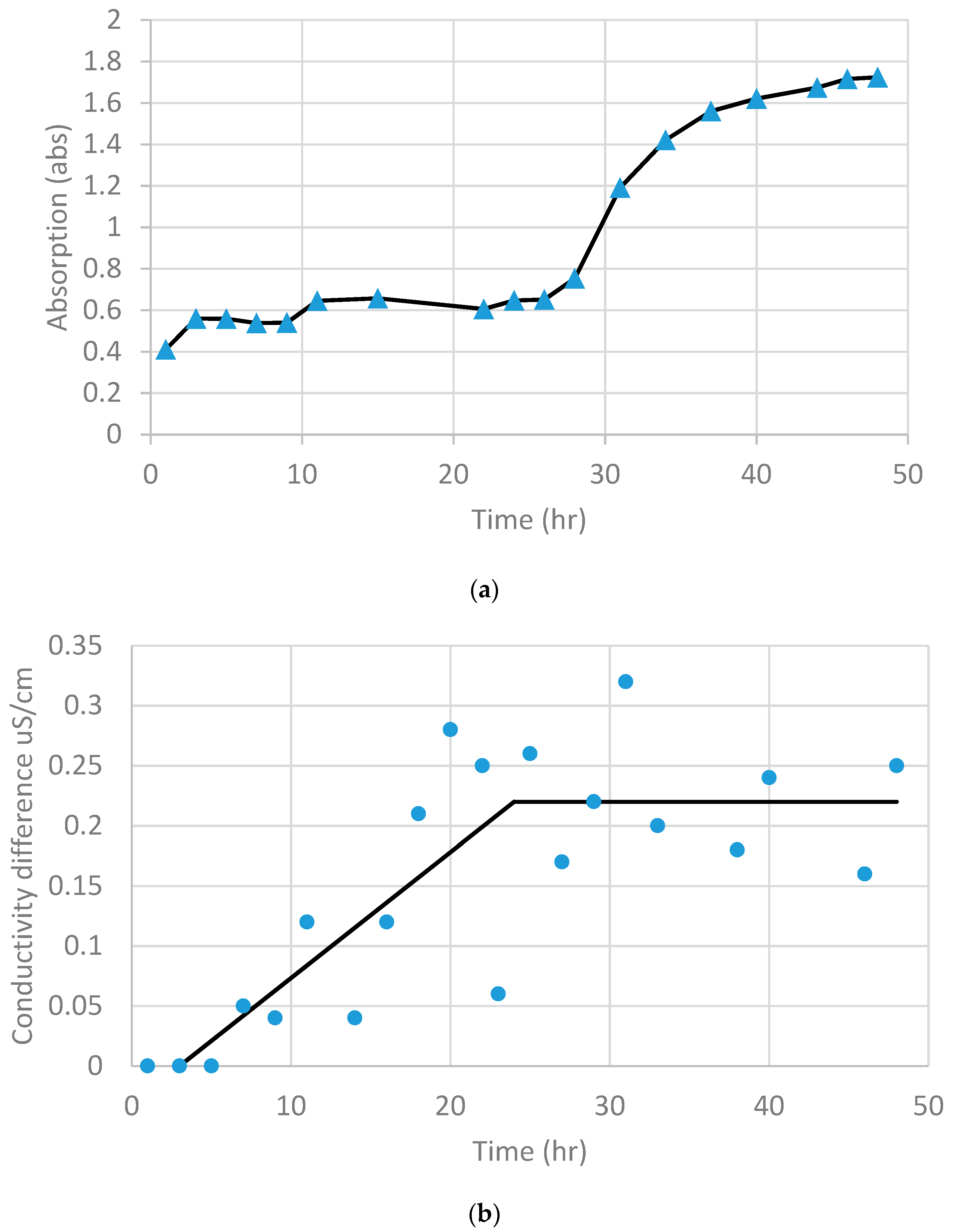
Figure 2.
Schematic view of the experimental setup for bentonite desiccation test.

Figure 3.
Procedure of digital image processing: (a) original image, (b) grey image, (c) binary image, (d) clear noise and smoothing, (e) skeleton of the crack network, and (f) crack segmentation.
Figure 3.
Procedure of digital image processing: (a) original image, (b) grey image, (c) binary image, (d) clear noise and smoothing, (e) skeleton of the crack network, and (f) crack segmentation.
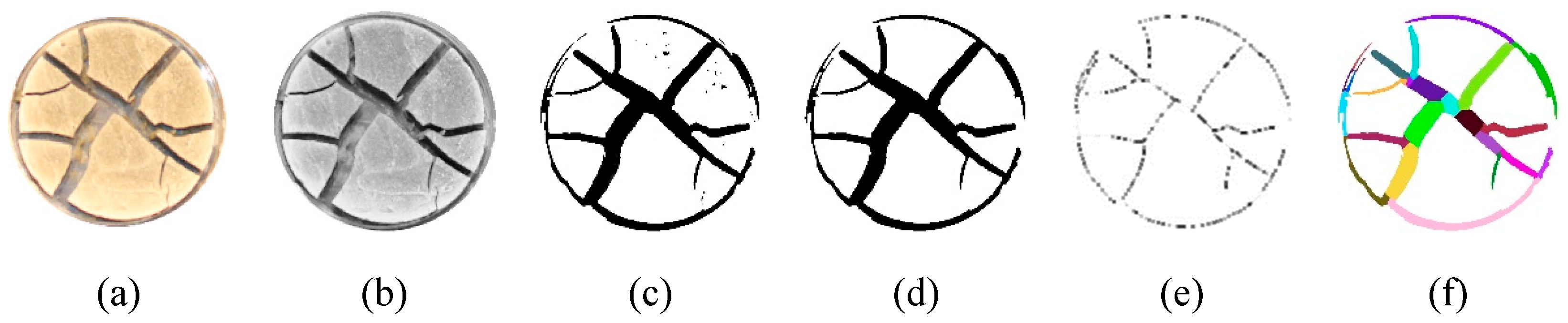
Figure 4.
Spatiotemporal evolution of crack pattern in bentonite treated with different solutions (time = 12, 24, 36, and 48 h).
Figure 4.
Spatiotemporal evolution of crack pattern in bentonite treated with different solutions (time = 12, 24, 36, and 48 h).

Figure 5.
Segmented crack patterns of bentonite samples treated with various solutions at 48 h: (a) sample W, (b) sample B, (c) sample C, (d) sample 25B75C, (e) sample 50B50C, and (f) sample 75B25C.
Figure 5.
Segmented crack patterns of bentonite samples treated with various solutions at 48 h: (a) sample W, (b) sample B, (c) sample C, (d) sample 25B75C, (e) sample 50B50C, and (f) sample 75B25C.

Figure 6.
SEM image of the partially cemented sample 75B25C: (a) comparison between cemented and less-cemented region; (b) calcite crystals among bentonite soil particles.
Figure 6.
SEM image of the partially cemented sample 75B25C: (a) comparison between cemented and less-cemented region; (b) calcite crystals among bentonite soil particles.

Figure 7.
Probability distribution of crack area of four soil samples after 48 h of drying.
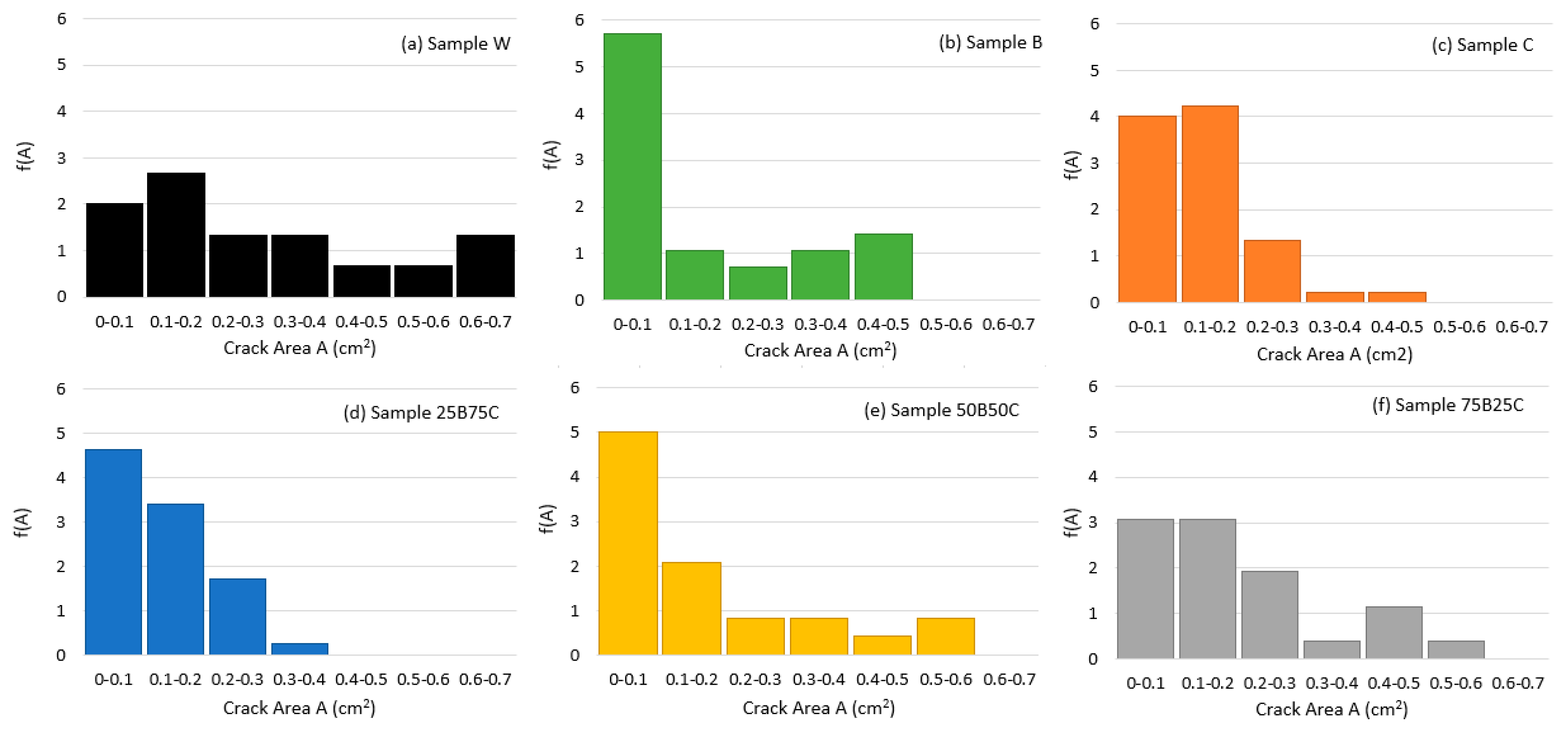
Figure 8.
Probability distribution of crack width of four soil samples after 48 h of drying.


Table 1.
Physical properties of the tested soil
| Soil Properties | Value |
|---|---|
| Specific gravity | 2.6 |
| Consistency limit | |
| Liquid limit (%) | 276 |
| Plastic limit (%) | 37 |
| Plasticity index (%) | 239 |
| pH | 8.5 |
| USCS classification | CH |
| Clay (< 2 ) | 46% |
Table 2.
Quantitative analysis results obtained from the 48-hour crack patterns of six soil samples
| Crack Parameters | Sample W | Sample B | Sample C | Sample 25B75C | Sample 50B50C | Sample 75B25C |
|---|---|---|---|---|---|---|
| Surface crack ratio (%) | 29.2 | 24 | 29 | 25.7 | 22.6 | 23.5 |
| Average crack width (cm) | 0.28 | 0.18 | 0.20 | 0.17 | 0.18 | 0.18 |
| Total crack length (cm) | 23.4 | 28.8 | 36.2 | 34.2 | 29.0 | 31.7 |
| Crack segment number (−) | 16 | 28 | 44 | 41 | 24 | 25 |
| Average crack length (cm) | 1.46 | 1.02 | 0.82 | 0.83 | 1.21 | 1.27 |
Table 3.
Desiccation time and water loss at the onset of desiccation cracking
| Sample Type | W | B | C | 25B75C | 50B50C | 75B25C |
|---|---|---|---|---|---|---|
| Surface crack initiation time (hr) | 2.5 | 5 | 4.5 | 16.5 | 16 | 17 |
| Critical water content | 93.5% | 81% | 85% | 72% | 77.3% | 66.6% |
© 2019 by the authors. Licensee MDPI, Basel, Switzerland. This article is an open access article distributed under the terms and conditions of the Creative Commons Attribution (CC BY) license (http://creativecommons.org/licenses/by/4.0/).
Share and Cite
MDPI and ACS Style
Vail, M.; Zhu, C.; Tang, C.-S.; Anderson, L.; Moroski, M.; Montalbo-Lomboy, M.T. Desiccation Cracking Behavior of MICP-Treated Bentonite. Geosciences 2019, 9, 385. https://doi.org/10.3390/geosciences9090385
AMA Style
Vail M, Zhu C, Tang C-S, Anderson L, Moroski M, Montalbo-Lomboy MT. Desiccation Cracking Behavior of MICP-Treated Bentonite. Geosciences. 2019; 9(9):385. https://doi.org/10.3390/geosciences9090385
Chicago/Turabian StyleVail, Mark, Cheng Zhu, Chao-Sheng Tang, Luke Anderson, Michael Moroski, and Melissa Tabada Montalbo-Lomboy. 2019. "Desiccation Cracking Behavior of MICP-Treated Bentonite" Geosciences 9, no. 9: 385. https://doi.org/10.3390/geosciences9090385
Note that from the first issue of 2016, this journal uses article numbers instead of page numbers. See further details here.