Low-Water Crossings: An Overview of Designs Implemented along Rural, Low-Volume Roads


Department of Agricultural & Biological Engineering, University of Illinois at Urbana-Champaign, 1304 W. Pennsylvania Avenue, Urbana, IL 61801, USA
*
Author to whom correspondence should be addressed.
Environments 2018, 5(2), 22; https://doi.org/10.3390/environments5020022
Submission received: 21 November 2017
/
Revised: 26 January 2018
/
Accepted: 29 January 2018
/
Published: 31 January 2018
Abstract
:Replacement of many old and aging bridges, culverts, and low-water crossings on rural low-volume roads is an increasing concern throughout the United States. The economic burden for many local bodies can be huge if these structures are to be replaced by a bridge or culvert. A low-water crossing (LWC) is a feasible and efficient road-stream crossing structure that can be used on these roads as an economical alternative to culverts and bridges. Three types of commonly used LWCs; unvented fords, vented fords and low-water bridges; their selection criteria, environmental considerations, design process, materials selection, signage and permitting requirements are included in this paper. Some of the issues with the existing LWCs are the safety in the crossing and effects on aquatic organism passage and surrounding environment. Through proper design, construction, and installation of proper signage, the functionality and reliability of LWCs can be improved. The study provides engineers and other practitioners in the United States and elsewhere with a proper set of information and design procedures for using LWCs.
1. Introduction
A low-water crossing (LWC) is a feasible and efficient road-stream crossing structure that may be implemented on roads with average daily traffic (ADT) of less than 25 vehicles. LWCs are road-stream crossing structures designed to be overtopped by high flows or by debris- or ice-laden flows [1]. At times when the structures are overtopped, the road will be closed to traffic, and alternative routes must be used. These relatively inexpensive structures are very useful across ephemeral streams and where the normal depth of flow is low.
In the United States, there are many old and aging bridges, culverts, and low-water crossings on rural low-volume roads that need to be replaced. The economic burden for local agencies can be huge if these structures are replaced by a bridge or culvert. For example, the Illinois Department of Transportation (IDOT) and local agencies are responsible for regulating and monitoring 146,764 miles (236,194 km) of roads in the state of Illinois. In Illinois, these structures are of use on farmland access roads that are used only a few times a year for transporting machinery, agricultural commodities, and supplies.
The paper provides an overview of the different types and implemented designs of low-water crossings throughout the United States. The outcomes are a part of the study that was conducted in order to aid the development of design guidelines for LWCs in Illinois. This paper will guide engineers and other concerned local authorities in the proper selection, design and construction of LWCs. In addition to guiding the practitioners through LWC assessment and implementation, this paper also addresses the environmental impacts of LWCs, including effects on Aquatic Organism Passage (AOP) and signage requirement for the safety of the users.
1.1. Low-Water Crossing Types
Three main types of LWCs, which are designed to submerge at some flows, include unvented fords, vented fords, and low-water bridges.
1.1.1. Unvented Fords
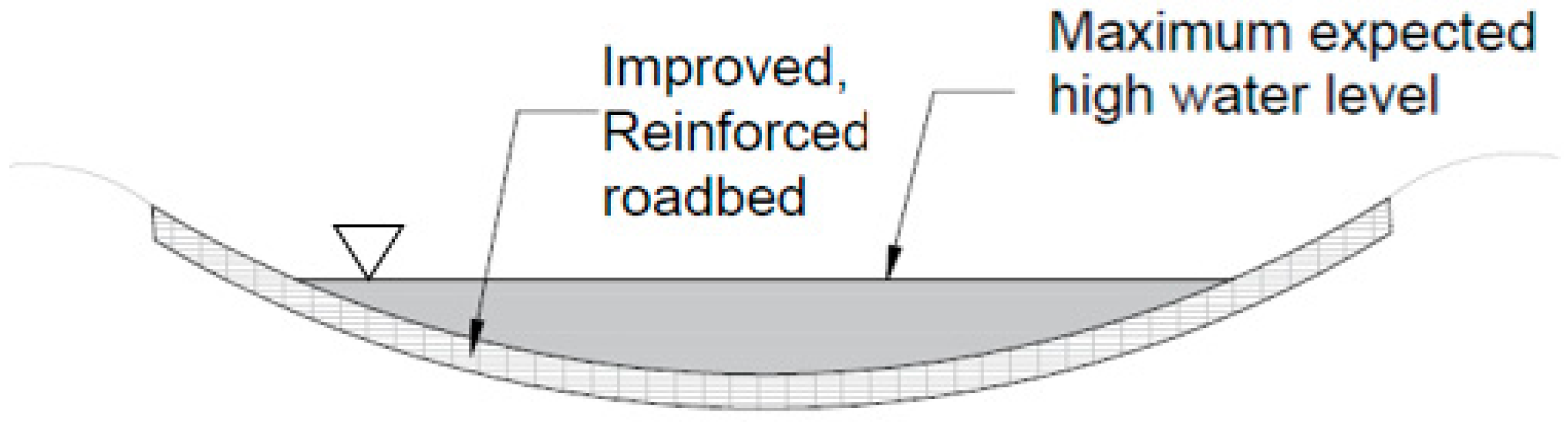
An unvented ford is a structure that crosses streams which are dry most of the year or where normal stream flow is less than or equal to 6 inches (15.2 cm) in depth. They are usually used for ephemeral streams or streams with shallow flows and cross streams at or slightly above the streambed. The crossing may be constructed of crushed stone, riprap, precast or cast-in-place concrete slabs, etc.
Based on the crossing surface, unvented fords are divided into unimproved and improved fords. Unimproved fords are simply natural crossings, usually placed at stable locations where the appropriate substrate already exists. Improved fords are placed at locations that need altering or strengthening in the substrate, and have a stable driving surface of rock, concrete, asphalt, concrete blocks, concrete planks, gabions, geocells, or a combination of materials (Figure 1).
Unvented fords are called “at-grade” if the crossing is placed directly on the channel bottom, whereas “above-grade” structures are raised to a certain height above the channel bottom.
1.1.2. Vented Fords
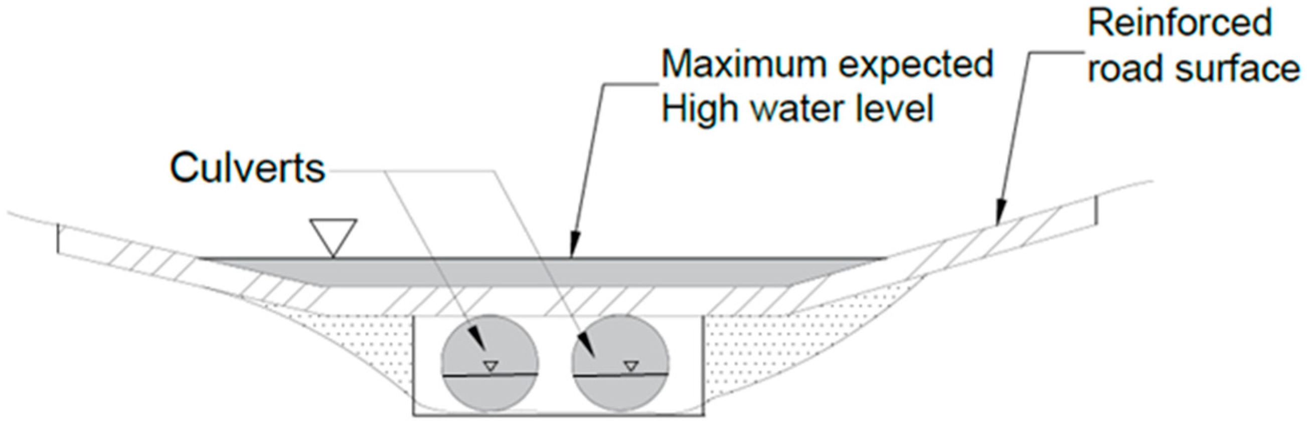
Vented fords have a driving surface elevated above the channel bottom with vents that allow low flows to pass beneath, keeping vehicles out of the water during low flow [1]. High water will periodically flow over the crossing. The pipes or vents may be embedded in earth fill, aggregate, riprap, or concrete. Vented fords are designed to pass low flow such as 1% exceedance flow or 1-year flow and higher flows pass over the structure. However, parts of the crossing such as approach roads, embankments, etc. are designed for higher flows such as 10 or 25-year flow, depending upon the desired lifetime of the structure. The vents can be one or more pipes (Figure 2), box culverts, or open-bottom arches.
1.1.3. Low-Water Bridge
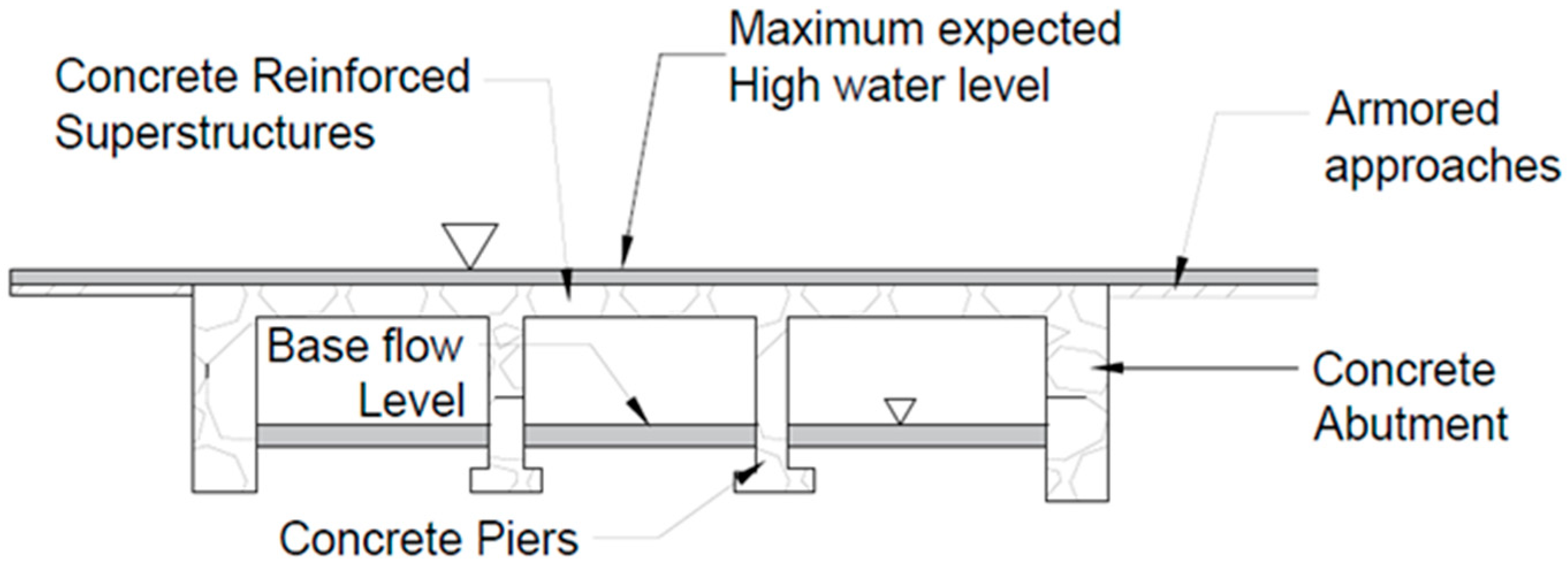
Low-water bridges are defined as open-bottom structures with elevated decks and a total span of at least 20 ft (6 m) [1]. They may include one or more piers with abutments and are structurally similar to other bridges except they are built lower, allowing periodic overtopping (Figure 3). They can pass higher flows underneath the driving surface than most vented fords. However, they are designed and installed expecting they will be under water at higher flows [2]. A low-water bridge is preferred where minimum disturbance to the channel geometry and aquatic organism passage is desired.
1.2. Current Status of LWC Design Guidelines
Various national and state agencies—such as the United States Department of Agriculture (USDA) Forest Service and the United States Army Corps of Engineers-Construction Engineering Research Laboratory (CERL), the Department of Transportation, and the Departments of Fish and Wildlife in several states—have published guidelines for construction of LWCs, making traffic conditions, aquatic organism passage, and stream morphology the primary criteria.
Federal Highway Administration (FHWA) published an executive summary [3] including the commonly used low-water crossings, selection criteria and design considerations based on the design and performance of existing structures. The USDA Forest Service published a LWC design manual [1], which consists of geomorphic, biological, and engineering design considerations. Similar studies conducted by CERL focused on the LWCs used in military operations [2,4], in which design and experiences with LWCs are detailed.
Iowa has a design and construction guidelines [5], which includes selection criteria, design, and construction of LWCs. A similar study conducted in Texas provides design guidance for LWCs in areas of extreme bed mobility [6]. Few studies have given special emphasis to the aquatic organism and fish passage in states like Massachusetts [7], Vermont [8], and Washington [9]. These guidelines focus on design, installation, and maintenance of stream crossings to provide aquatic organism passage and aquatic habitat connectivity in the streams.
2. Materials and Methods
This section discusses in detail the Illinois LWC survey, LWC site considerations, suitability, economic and environmental consideration that should be considered during the selection of a LWC at a site.
2.1. Illinois LWC Survey
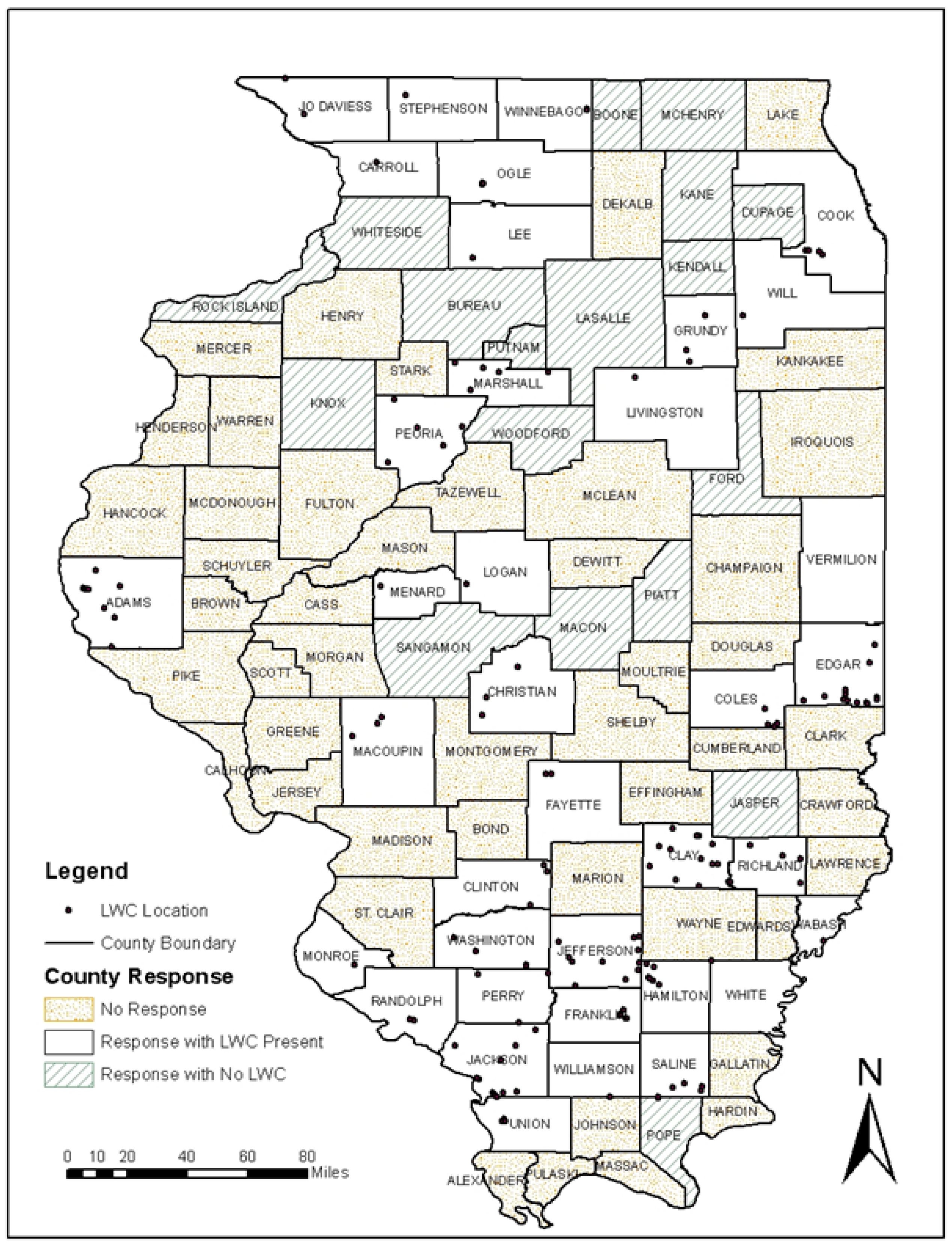
A survey was conducted in Illinois counties to obtain an overview of the distribution of LWCs, along with engineers’ experiences with LWCs design, construction, and maintenance. Out of the 55 counties which responded, 18 counties indicated of not having any LWCs. A total of 155 LWCs were identified in the remaining counties (Figure 4); 47 unvented fords, 106 vented fords, and 2 low-water bridges. Of the 47 unvented fords, 33 are at-grade structures. These LWCs are used for farmland access, residence access, park roads, forest roads, drainage, etc. 36 of the LWCs have warning signs, whereas most of those (119) lack warning signs. Some of the key findings of the LWC survey are as given below:
- LWCs are suitable for areas with average daily traffic less than 25 vehicles per day.
- LWCs, especially unvented and vented fords, are economical and hence suitable for rural, low ADT roads that primarily serve as access roads to farmlands.
- The duration for which a LWC is allowed to be overtopped depends on the usability and importance of the road. Usually, it is limited to less than 5% of the time in a year.
- Few LWCs provide access to residential homes, which is suggested only in the presence of an alternative route nearby.
- Lack of warning signs increases the risk of accidents in the crossings and is a liability to a highway department. Thus, proper signage should be installed at the LWC site.
2.2. LWC Site Considerations
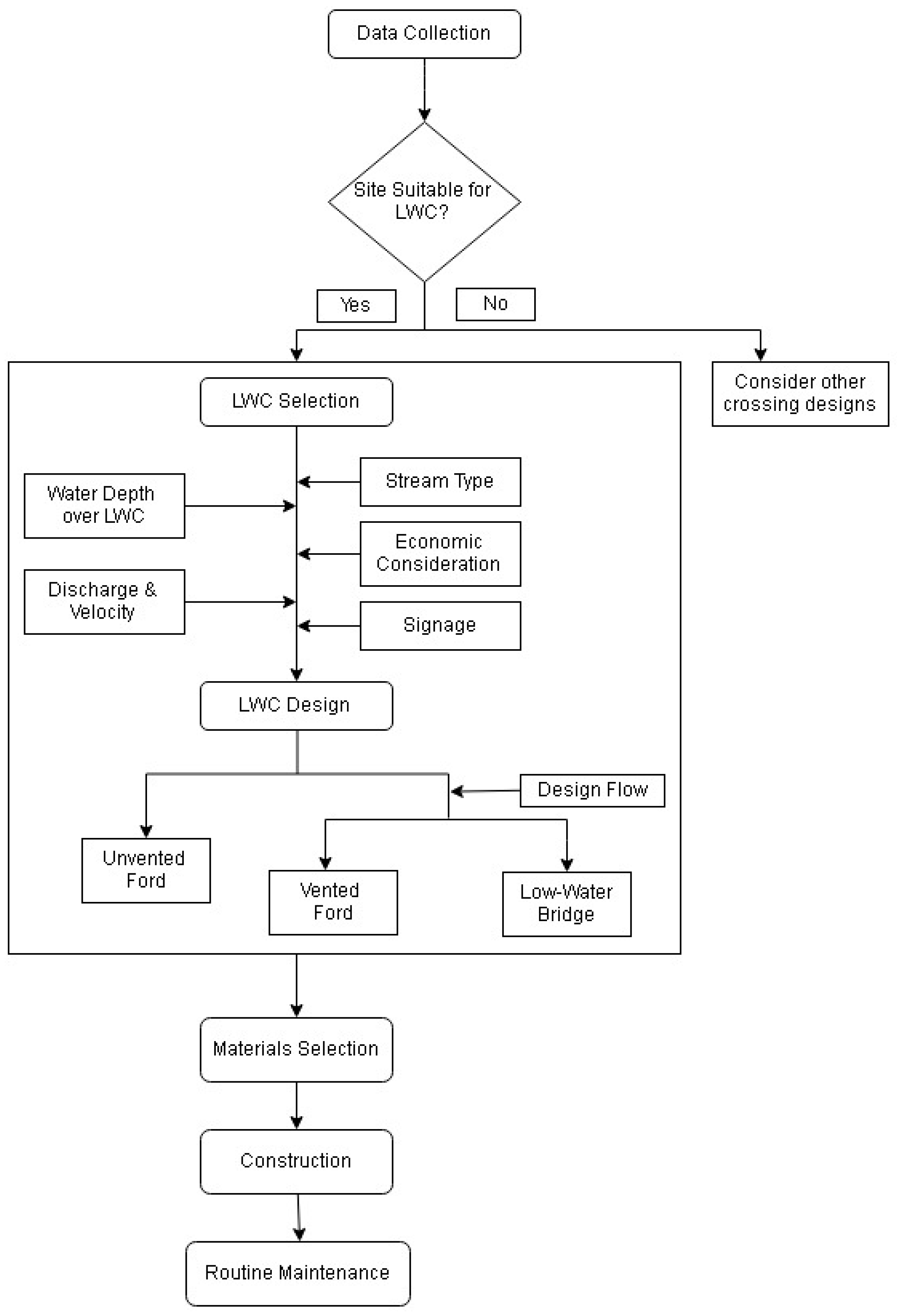
Figure 5 is a flowchart showing LWC selection, design and construction steps, and important factors to consider in the process. The first step is data collection and deciding whether a LWC is a suitable option for the site. A suitable LWC can then be selected for the site considering stream type, flow, economic consideration, etc. The next step consists of LWC design and construction, before which necessary permits should be obtained.
2.3. Suitability of LWC
LWCs are appropriate at stable sites where the proposed design matches with channel geometry, bed material, and flow characteristics and conforms to safety and access requirements. LWCs are not appropriate on roads that access essential public facilities or that serve as the only public route to an area. Many states restrict construction of LWCs on school bus routes and roads required for national defense.
Fords with the low vent-area ratio (VAR) are undesirable because they act as low dams when the flow in the channel exceeds the vents’ capacity, and the backwater may lead to bank erosion and channel widening. The following questions should be considered when deciding whether a LWC is a feasible option in the stream [1,2].
- How frequently is the road used? Are there any alternative routes nearby? Is traffic volume or type likely to change in the future?
- What kind of area does the road serve? What size vehicles are expected on the road?
- Is the crossing located near unstable landforms such as landslide prone areas? Is the site in an active floodplain, or is the channel entrenched?
- Is there a current LWC? If yes, how is it affecting the stream?
- What kind of materials do the stream bottom and substrate consist of—rock, cobble, gravel, sand, silt, or clay?
- What kind of flow is predominant in the stream—base flows or peak flows? Is the flow sediment and debris-laden?
- Are there any constraints such as private property or archeological sites, threatened and endangered species, sediment or total maximum daily load requirements?
- Should the crossing be designed for passage of special aquatic animal species?
- What is the accident history of the road? Do sight distance, geometrics, and design speed permit safe movement on the road?
- What are the maintenance and erosion control requirements?
2.4. LWC Economics
The design of LWCs should always be accompanied by an economic analysis that encompasses construction cost, maintenance cost, and damage to property and lives associated with the flooding conditions. The LWC selection process should minimize the total annual cost of the installation over the life of the structure.
2.4.1. LWC Cost
The major costs associated with the LWC construction are the cost of material, embankment, protection structures, and signage. In Illinois, the average cost of construction of an unvented ford with asphalt pavement is $10 per square foot ($110 per square meter), whereas vented fords on average cost $65 per square foot ($700 per square meter). Similarly, low-water bridges can be constructed for $120–$160 per square foot ($1290–$1720 per square meter).
In the case of vented fords, the shape also plays an important part in cost. Circular pipes are found everywhere, are reasonably priced, can withstand high structural loads, and are hydraulically efficient. However, pipes with low VAR are not recommended. Arches and ellipses are more expensive and require additional attention to their foundations. Precast box culverts take less time to install compared to cast-in-place installations but may be associated with additional handling cost.
2.4.2. Service Life
The service life of LWCs should be considered when selecting the appropriate type of LWC. If the LWC is located where replacement would be impractical, a longer service life is desired, and the LWC and materials should be selected accordingly. In areas where changes are expected in traffic patterns or if the roads will be rebuilt in a relatively short time, a LWC with a shorter service life can be an option.
2.4.3. Risk Analysis
Risk analysis is necessary for LWC installations on major roads or those located in areas with high potential flood damage. The objective of the risk analysis is to find the best LWC capacity and design based on a comparison of costs and benefits. Risk analysis should be performed on the alternative designs to find the best design, associated with the least total expected cost following Hydraulic Engineering Circular No. 17 (HEC-17) [10].
2.5. LWCs and Environment
Environmental effects must also be considered when deciding whether to use LWCs. Fords, especially simple unhardened crossings, are subject to runoff and gullies at the ingress and egress of the crossings. When heavy vehicles cross streams, they can greatly contribute to stream bank and soil erosion in the area due to excessive vegetation loss and soil disturbance [2,4]. Field studies of hardened LWCs have shown that when implemented properly these crossings maintain stream water quality, reduce stream habitat fragmentation, and decrease maintenance expenses over the unimproved fords [4,11]. Specific environmental issues associated with the construction of at-grade unimproved fords include effects on water quality and bank stability.
Vented fords keep vehicle tires dry during base flow conditions, keeping soils and other pollutants from vehicles from entering the stream [2]. However, vented fords can also cause the stream to lose its natural hydrological properties, and culverts can clog due to debris and sediment [2]. The geomorphic response of streams at vented fords at Fort Riley, Kansas, included: mean riffle spacing upstream of the LWCs was double that of downstream reaches, greater deposition of fine sediments occurred directly upstream, and incised channels downstream. The vented fords also slowed or blocked the transportation of water, sediments, and debris downstream during bankfull flows.
Low-water bridges have an elevated driving surface, maintain a more natural streambed, allow more natural sediment and aquatic organism movement than culverts, and are the best LWC type for fish passage [1]. Low-water bridges can be more expensive to design and build, and they are still susceptible to clogging under conditions such as high debris loading [2].
Wang et al. [12] deduced that most of the sediment entering the streams following road construction was from the stream crossings and approaches to the crossings. When the approach fill slopes became re-vegetated, they stabilized, and the annualized sediment loads declined; however, sediment exports remained above the pre-disturbance levels. Studies have shown that best management practices (BMPs) could effectively reduce erosion and total suspended sediment loads near LWCs [13,14]. Brown et al. [13] found that approaches to the stream crossing have a high potential for impacting the water quality in the stream. They concluded that implementation of BMPs such as hardening of the surface and appropriate spacing of water control structures could reduce sediment delivery to streams.
2.6. Aquatic Organism Passage Considerations
Common ways in which LWCs create an obstruction to aquatic organism passage (AOP) include drops at inlet and outlet, excessive water velocity, debris, excessive turbulence due to contraction at inlet region, insufficient low flows, etc. [15]. Studies have shown that stream crossings may change the form and function of stream ecosystem and habitat significantly and affect aquatic organism movement [16,17,18]. Warren Jr & Pardew [19] looked into movement of fish for 21 different species in seven families through the culvert, slab, open-box, and ford crossings and through natural reaches and found that overall fish movement was an order of magnitude lower through culverts than through other crossings or natural reaches. They also found that open-box and ford crossings showed little difference from natural reaches in overall fish movement.
Changes in stream hydrology and velocity occur when there is an alteration in the channel geometry that restricts movement and may also be inhospitable for many fish and invertebrate species [17]. Diebel et al. [20] surveyed 190 road crossings and found that 74% of them acted as a barrier to the movement of aquatic species, mostly due to high water velocity, low water depth and outlet drops.
At-grade improved fords and some unhardened fords that are improved with gravel, riprap, etc. may lead to the disruption of the substrate continuity, which can impede the movement of benthic organisms. The scouring at downstream end and the resulting drop in these LWC locations can impede the upstream movement of aquatic organisms. In case of Vented Fords, the high-water velocity, shallow water depth, inlet and outlet drops can result in various barriers (velocity barrier, jump barrier, exhaustion barrier, turbulence barrier, and behavioral barrier), substrate discontinuities and migration delays for the aquatic species. Even low-water bridges act as barriers to AOP when they are significantly undersized.
For improved AOP, the crossing should be similar in form and function to the natural bed of the stream channel [1,17,21]. Stream simulation provides a unique approach to providing AOP at road-stream crossings that avoids flow constriction during regular conditions and resists scouring during high flood conditions [22,23]. This is also supported by the study conducted by Barnard et al. [24], where they found that only one culvert out of the studied 50 had significant bed degradation from record flooding conditions. Fords with slots or small channel to allow AOP during very low flows provide a little hindrance to organism passage if they mimic the form of the reach [1,2]. Unvented at-grade LWCs with streambed materials on the driving surface help in the passage of aquatic species. A series of embedded box culverts can be used in areas where aquatic organism habitat protection is of prime importance.
Designing LWCs for AOP might result in a larger structure for hydraulic conveyance, but it has additional benefits of low maintenance and is economically feasible in the long run [25]. It is advised to consult Hydraulic Engineering Circular No. 26 (HEC-26), Culvert Design for Aquatic Organism Passage [15] while designing the crossing so that the LWC also facilitates adequate AOP. A current version of the list of endangered and threatened species, prepared by the corresponding state’s Department of Natural Resources, should be consulted.
3. LWC Design Guidelines
This section discusses about the design flows, selection and design of different LWCs, permitting, construction, signage and maintenance of the structures.
3.1. Site Hydrology
The important factors in LWC design are high flow and normal (or base) flow. The high design flow dictates the expected water level above the LWC structure as well as the length of road surface that will be under the water. The normal or base flow will help the user decide which LWC to construct at the site. Although LWCs are designed to be overtopped by higher flows, it is not desirable that LWCs flood most of the year. The experience of local highway officials with LWCs, as well as the literature [3], suggests that the favorable condition for a LWC is when average annual flooding is less than two times a year, whereas it is undesirable to use an LWC when flooding is more than ten times a year. Thus, the LWC should be designed such that it is functional at least 95% of the time in a year.
If there are gauging stations present in the stream, then the available data from the gauging station should be utilized to obtain the design flow. In instances where the measured flow data is not available, rating curve can be employed if available. For the design of LWCs, two approaches to obtain design flow that are generally used have been described below. It should be noted that the Drainage-Area Ratio method [26], does not take precipitation in the catchment as an input, hence it does not account the effects of changing hydrological conditions caused by climate change and other factors. The flood frequency approach utilizes the past data to estimate the future conditions, under the assumptions of stationarity, which has been challenged by many studies. It is recommended to not just rely on these two methods, but also look into other methods of estimation of the design flood.
3.1.1. Flow-Duration Approach
The flow-duration curve (FDC) is a plot that indicates the percentage of time that the flow in a stream of interest is equaled or exceeded. The exceedance probability (e) can be used to determine the number of times per year a LWC will be closed. For example, a 5% exceedance probability means that the crossing will be closed, on average, for 18 days a year. During those days, the design discharge is equaled or exceeded, and the LWC is overtopped. The FDC for gauged streams can be prepared based on the available daily streamflow data. The FDC for ungauged catchments in Illinois is discussed in a United States Geological Survey (USGS) report, Estimation of Regional Flow-Duration Curves for Indiana and Illinois [26]. The study divides the state of Illinois into three different regions. The drainage-area ratio (DAR) method, discussed in the study, is more applicable for LWCs because the only parameter required in this method is drainage area in square miles. The flow-duration-area curves for three regions in Illinois are provided in Bhattarai et al. [27].
3.1.2. Flood-Frequency Approach
The flood-frequency approach is a relatively simple method of hydrologic design. Crossing components are usually designed for 10 or 25-year flow, whereas the pipe in a vented ford is designed to pass a 0.5 or 1 year event. For gauged streams, the design discharge can be computed by flood-frequency analysis of the yearly maximum discharge values over a long range. It is recommended that USGS StreamStats (Reston, VA, USA) be used for ungauged catchments in Illinois. It provides information on peak discharges, drainage area, stream slope, and average soil permeability. More information on the method used by StreamStats can be found in the USGS report, Estimating Flood-Peak Discharge Magnitudes and Frequencies for Rural Streams in Illinois [28]. The lowest peak discharge that StreamStats gives is Q2, which has a return period of two years. In certain areas, using this discharge to design the structure may result in a larger structure than required. In such cases, partial duration equations can be employed to obtain design discharge of return periods of 0.8 years, 1.01 years, 1.5 years, etc. More information on Partial Duration Series (PDS) regional equations can be found on the same USGS report [28].
3.2. Selection of LWC Type
Selection of a LWC for a location depends on several factors such as traffic volume, stream channel conditions, anticipated flow in the stream, the cost of construction and maintenance, etc. Condition 2 of Nationwide Permit states “No activity may substantially disrupt the necessary life cycle movements of those species of aquatic life indigenous to the waterbody, including those species that normally migrate through the area, unless the activity’s primary purpose is to impound water”. Thus, LWCs should be designed such that the movement of aquatic species is not hampered. At times when there is presence of endangered species in the stream and AOP is of main concern, then vented fords should be avoided and either low-water bridge or improved ford should be adopted. Some of the LWC types suggested for different conditions are as follows:
- An unimproved ford is suitable for an area that has an ephemeral stream with the low base flow and where AOP is an important consideration.
- If the channel bottom is unstable and erodible, an improved ford with a hardened crossing is preferred.
- If the stream carries a large amount of sediment and debris, an unimproved or improved unvented ford is suitable.
- For an incised channel, a vented box culvert is a suitable option.
- For a broad channel or stream associated with the large base flow and high flood peaks, a low-water bridge should be considered.
- If a barrier is needed to exclude exotic species, an improved unvented ford with a raised platform or a raised vented ford with a perched outlet should be considered.
3.3. Design of Unvented Fords
Unvented fords are simple to design and are very effective in certain conditions such as ephemeral streams. Fords on channel bottoms are good for sites with a stable streambed, or where minimum strengthening of bed is required. Raised unvented fords can be used where the depth of normal flow exceeds 6 inches or the approach roads are higher than the stream bed.
3.3.1. Ford on the Channel Bottom
For fords constructed on a channel bottom, the discharge and velocity can be estimated using Manning’s equation. Assuming a rectangular channel, the design discharge () can be found by using Manning’s and continuity equations. For wide channels with , the equation can be simplified as
where n is the Manning’s roughness coefficient, w is the width of the channel in feet, h is the depth of flow in feet, and S is slope in ft/ft.
The computed value of h should be less than the allowable maximum flow depth of 6 inches (15.2 cm) for ford on the channel bottom to be a viable option at the LWC site.
3.3.2. Raised Unvented Ford
To find the depth of flow, the empirical equation developed by Rossmiller et al. [29] and used in the design of low-water crossings in Iowa [5,25] can be employed:
where L is the length of LWC normal to flow in feet, and H is the upstream head of water above the level of ford, h is the depth of water above the level of ford at the center of the roadway.
Combining above two equations results in
3.4. Design of Vented Ford
Vented fords are treated as culvert with weir flow over the road when the water overtops the structure [25]. In this case, a portion of the total design flow () passes above the structure (), while the remaining part of the flow is designed to pass through the vent or pipes (). The flow over the top of the vented ford is limited to 6 inches (15.2 cm) in depth, similar to the unvented ford. This flow can be estimated using the weir equation used for the raised unvented ford:
Using the maximum allowable depth of water (h) of 0.5 ft and considering H = h/0.6, we can obtain the flow overtopping the ford by substituting it in above equation as
Now the capacity of pipes in vented ford is given by
After determining the discharge through the vent, the size of the pipe may be found by following the methods used for culverts, among which culvert hydraulics and flow equations [31,32] and Hydraulic Engineering Circular No. 5 (HEC-5) charts [32,33] are recommended. The graphs for the pipe size vs. capacity is given in Bhattarai et al. [27].
3.5. Design of Low-Water Bridges
The hydraulic analysis and design of low-water bridges are done the same way for normal bridges, with special consideration given to overtopping flows [34]. The design should incorporate consideration for scour and stream stability. It is recommended to use HEC-RAS for the hydraulic analysis of the low-water bridge. Two bridge designs for low-volume roads are provided: the slab bridge design and the precast concrete channel beam bridge design. The designs should meet all the American Association of State Highway and Transportation Officials (AASHTO) requirements as given in the Standard Specifications for Highway Bridges [35] and IDOT’s Standard Specifications for Road and Bridge Construction [36].
3.5.1. Slab Bridge
Slab bridges are short-span bridges that are frequently constructed in areas where shallow structure depths are required. With slab bridges, the deck slab also serves as the main load-carrying component of the bridge. The slab bridge should be designed following either the Load and Resistance Factor Design (LRFD) or Load Factor Design (LFD) process. The design procedures are given in the Illinois Bridge Manual [37]. The Illinois Bridge Manual limits the maximum span of the slab bridges to 40 ft (12 m), which is appropriate for LWCs. For a longer length of spans, continuous slab design must be used [37].
3.5.2. Precast Concrete Channel Beam Bridge
Precast concrete channel beams are a suitable option for short-span bridges. These beams are commonly available for spans from 16 ft (4.8 m) up to 40 ft (12 m) in length. The beams are positioned and tied together, which also acts as the superstructure of the bridge. In these bridges, the stems of the channel resist flexural as well as shear forces, and the flange acts as bridge deck [38]. The asphalt wearing surface is an optional element for LWCs. They are beneficial as LWCs due to reduced construction time, long life, and low maintenance cost.
3.6. Low-Water Crossings Permitting
Development of low-water crossings must be permitted through several regulatory agencies before commencing construction. The regulatory agencies include U.S. Army Corps of Engineers, Department of Natural Resources, Environmental Protection Agency, Soil and Water Conservation District and other local bodies.
The U.S. Army Corps of Engineers Nationwide permit condition 2 states “No activity may substantially disrupt the necessary life cycle movements of those species of aquatic life indigenous to the waterbody, including those species that normally migrate through the area, unless the activity’s primary purpose is to impound water. All permanent and temporary crossings of waterbodies shall be suitably culverted, bridged, or otherwise designed and constructed to maintain low flows to sustain the movement of those aquatic species. If a bottomless culvert cannot be used, then the crossing should be designed and constructed to minimize adverse effects to aquatic life movements”.
The agency responsible for authorizing a permit depends on the type of permit required. If all required permits are not authorized by the proper permitting agencies, construction is not allowed. The quantity and type of permits required for each low-water crossing may vary depending on location, project size, and other specifications such as threatened and endangered species. The most common authorizations required for this type of construction activity are Clean Water Act Section 401 certification, 402 National Pollution Discharge Elimination System, and 404 Dredge and Fill permits. These controls set water quality standards, authorize discharge into a water of the U.S., and may allow dredge and fill to a wetland or waterbody. A single low-water crossing may require one or all authorizations before construction begins.
For example, agencies involved in the permitting process for Illinois include both national and state agencies such as the U.S. Army Corps of Engineers (USACE), Illinois Department of Natural Resources (IDNR), Illinois Environmental Protection Agency (IEPA), and can involve other local, regional, or county agencies. The state of Illinois has created a joint permit application option for construction activities to expedite the permitting process. The joint application may be filed concurrently with IEPA, IDNR, and USACE for independent review. The Illinois Joint Permit Application for Construction is a dual-purpose application for both 404 and 401 authorization and certification.
3.7. Materials Selection and Construction
3.7.1. Unvented Fords
The selection of materials should be done carefully in the case of unvented fords because water in the stream constantly overtops the crossing surface. Commonly used materials include compacted earth, Portland cement concrete, interlocking blocks [2], gravels, riprap, and gabions [39]. The crossing surface should be stable and should not wash away due to the flow over it. Depending on channel stability, appropriate protection should be provided to the streambed using gravel, riprap, or geotextile materials. Sidewalls and bank erosion protection may be required, which can be achieved using riprap and gabions.
3.7.2. Vented Fords
Vented fords consist of pipes, crossing surface, approach roads, sidewalls and cutoff walls. IDOT’s standard specifications should be followed during the installation of pipes or vents, which depends on the material selected. The crossing surface in vented fords can be constructed similar to unvented fords, using gravel or reinforced concrete. Surfaces should be constructed such that water does not pond after being overtopped. Sidewalls and cutoff walls are constructed to provide protection to the sides of the structure. The sidewalls may be constructed of concrete, riprap, or geotextiles. Similarly, the approach roads can be improved using the crossing materials to reduce erosion. Bank erosion control can be achieved using gabions or riprap when necessary.
3.7.3. Low-Water Bridges
A low-water bridge construction consists of foundation (footing or pile), substructure (piers and abutments), superstructure (beams and bridge deck), and approach roadway [3,5]. Construction of these bridges should conform to AASHTO specifications [35]. With low-water bridges, the deck of the bridge acts as the crossing surface. Based on site conditions, bank scour protection measures such as gabions or riprap may be installed like the unvented fords. While a guardrail provides additional safety to the traffic, it also collects debris when the structure is overtopped, which is undesirable in the case of LWCs.
3.8. LWC Signage
While a LWC does provide a safe alternative to bridges and culverts most of the time, it becomes unsafe to use in instances when the water level rises above the tolerable limit. Proper dissemination of the information regarding the condition of the LWC, and use of proper signage in the LWC area is necessary to increase the safety, reliability and functionality of the structure.
3.8.1. Liability
Flashy streams, which are a common occurrence at a LWC site, can cause loss of life and damage to property. Most commonly used cars and sport utility vehicles (SUVs) get carried away by 2 ft (60.9 cm) of water, or even less in some cases [40]. LWCs can be of considerable concern to engineers and governing bodies because of perceived potential legal liability. Carstens and Woo [41] concluded that the liability is minimized when LWCs are prevented from being used while flooded. With adequate warning, the potential for accidents and subsequent tort claims may be decreased by using LWCs rather than deficient and obsolete bridges [41].
3.8.2. Safety and Signage
Safety of road users is a primary concern in installing a LWC at any site. Static warning signs on the approach to a LWC, markers along the edge of hardened surfaces, and water depth gauges are required for the safety of those using a crossing [2,5,40]. Many drivers have trouble judging the speed and depth of water over the road in a LWC and enter the flooded roadway. Low visibility at night and muddy water during flooding conditions pose additional problems to drivers in making judgments under these conditions. In the absence of any informative signs, drivers set their criteria to determine whether the road is passable, which might lead to loss of life and property. LWCs should be treated like flood-prone roadways, and proper signage should be provided for the safety of the road users. Flood advisories and flash flood warnings should be issued to public via radio stations and messaging services so that the drivers can be alert to the floodwater situation.
For the safety of those using LWCs, it is recommended to use two warning and one regulatory sign in advance of LWCs [3,5,41]. Signage in a LWC area should start at least 750 ft (230 m) ahead of the crossing on both sides of the crossing. The FLOOD AREA AHEAD sign should be placed along with the posted speed. The IMPASSABLE DURING HIGH WATER sign should be placed 450 ft (140 m) ahead, and the DO NOT ENTER WHEN FLOODED sign at 200 ft (60 m). In areas where water can back up to more than 750 ft (230 m) on the either side of the structure during the flooding events, it is recommended to place the FLOOD AREA AHEAD sign more than 750 ft (230 m) from the structure, in addition to the minimum requirement discussed previously. Additionally, a LOW WATER CROSSING sign may be used to warn people of a low-water crossing ahead. The sign should be placed 500 to 700 ft (150 to 210 m) in advance of the low-water crossing.
Apart from static signage, dynamic message signs displaying messages such as CAUTION—WATER ON ROAD or ROAD CLOSED AHEAD DUE TO FLOODING may be installed along with flashing lights, based on the use of the road, the budget of the public agency, and the frequency of flooding at the LWC site.
3.9. Best Management Practices
In the case of LWCs, BMPs exist for a variety of management activities, including both in and near the channel. It is necessary to incorporate standard erosion and sediment control practices into the projects to maintain the water quality. The implementation and effectiveness of BMPs should be monitored, and additional maintenance needs should be identified. Some of the BMPs that apply to the construction of LWCs are discussed below:
- Erosion Control Plan should be created and implemented for preventing sediment from reaching the drainage.
- Construction activities should be done during the dry season or when precipitation and runoff are unlikely, whenever possible.
- Approaches and road surfaces with adequate strength should be constructed to support the treadway, shoulders, subgrade, and traffic loads.
- Service and refueling areas should be kept far from wet areas, surface water, and drainages. The soil contamination potential can be minimized by using berms around the sites and using impermeable liners.
- Heavy equipment should cross or work in and near streams only with specific protection requirements. During excavation, there should be a minimum disturbance on natural streambeds adjacent to the structure.
- The stream flow around construction sites should be diverted and returned to the natural stream course as soon as possible after construction or before the wet season.
- Control of Road Drainage by providing dips that shunt water off the road. Riprap should be sized and installed to resist erosive water velocities.
3.10. LWC Maintenance
Low-water crossings require routine inspection and maintenance to achieve their design service life. Structures and approaches may suffer deterioration from either large runoff events or normal use. Regular inspection of the LWC structures can help in identifying and correcting the minor problems, thus significantly reducing the risk to public safety and saving the repair or replacement costs. Inspections also help in identifying the long-term maintenance requirements. The inspection should consider structural integrity, hydraulic performance, and roadside compatibility to make sure that the structure is functioning well. The inspector should assess the LWCs based on the inspection schedule which considers the size of the openings in vented ford, condition rating of the structure, age of the structure, ADT, environmental conditions, etc. At a minimum, an annual inspection and maintenance are necessary to ensure structure and channel compatibility, function, and stability.
4. Discussion
The contents and findings in this paper is a result of the research conducted by the authors while developing design guidelines for low-water crossings in Illinois. It has been concluded that LWCs are feasible road-stream crossing structures on rural, low-volume roads. However, these structures should not be used on primary roads, as the structure is designed and expected to be overtopped by higher flows. The duration for which a LWC is allowed to be overtopped depends on the usability and importance of the road. Usually, it is limited to less than 5% of the time in a year. Low-water bridge has least impact on the environment, and has low maintenance cost. Implementation of proper signage is required in the LWC site to increase for safety considerations. Similarly, best management practices should be adapted during every phase of design, construction and maintenance in order to have least impact on the environment and aquatic organisms in the stream.
5. Conclusions
The paper provides an overview of the different types and implemented designs of low-water crossings throughout the United States. LWCs are feasible road-stream crossing structures on rural, low-volume roads with average daily traffic less than 25 vehicles. Selection of the type of LWC to use depends on many factors, including the traffic volume, environmental and AOP considerations, availability of construction materials and budget for the work. The research findings will help the county engineers and other stakeholders in selection, design, construction and long-term maintenance of the crossings in rural areas with low traffic conditions throughout the United States and elsewhere.
Acknowledgments
The authors would like to gratefully acknowledge the Illinois Center for Transportation for funding the project R27-148 “Development of Low-Water Crossing Design Guidelines for Very Low ADT Routes in Illinois”. The authors gratefully acknowledge the input and expertise provided by Prasanta Kalita, Heidi Howard, Niels Svendsen and Daniel Gambill for the research project.
Author Contributions
Sudip Gautam and Rabin Bhattarai conceived and designed the study; Sudip Gautam performed the modeling and experiments under guidance of Rabin Bhattarai; Sudip Gautam and Rabin Bhattarai wrote the paper.
Conflicts of Interest
The authors declare no conflict of interest.
References
- Clarkin, K.; Keller, G.; Warhol, T.; Hixson, S. Low-Water Crossings: Geomorphic, Biological, and Engineering Design Considerations; U.S. Department of Agriculture Forest Service: Washington, DC, USA, 2006.
- Howard, H.R.; Svendsen, N.; Holmes, J.; Holscher, J. Low-Water Crossings—Lessons Learned; PWTB 200-1-115; U.S. Army Corps of Engineers: Washington, DC, USA, 2011. [Google Scholar]
- Motayed, A.K.; Chang, F.M.; Mukherjee, D.K. Design and Construction of Low Water Stream Crossing—Executive Summary; Report No. FHWA/RD-83/015; Federal Highway Administration (FHWA), U.S. Department of Transportation: Washington, DC, USA, 1983.
- Svendsen, N.G.; Kalita, P.K.; Gebhart, D.L.; Denight, M.L. Defilade, Stationary Target and Moving Target Embankment, Low Water Crossing, and Course Road Designs for Soil Loss Prevention; ERDC/CERL TR-06-31; U.S. Army Corps of Engineers: Washington, DC, USA, 2006. [Google Scholar]
- Lohnes, R.A.; Gu, R.R.; McDonald, T.; Jha, M.K. Low Water Stream Crossings: Design and Construction Recommendations; CTRE 01-78; Iowa State University: Ames, IA, USA, 2001. [Google Scholar]
- Thompson, D.B.; Cleveland, T.G.; Fang, X.; Wang, K.H. Design Guidance for Low-Water Crossings in Areas of Extreme Bed Mobility, Edwards Plateau, Texas; FHWA/TX-08/0-4695-3; Texas Department of Transportation: Austin, TX, USA, 2009.
- Singler, A.; Graber, B. Massachusetts Stream Crossings Handbook; Massachusetts Riverways Program, Department of Fish and Game: Boston, MA, USA, 2005.
- Bates, K.K.; Kirn, R. Guidelines for the Design of Stream/Road Crossings for Passage of Aquatic Organisms in Vermont; Vermont Department of Fish and Wildlife: Montpelier, VT, USA, 2009.
- Barnard, R.J.; Johnson, J.; Brooks, P.; Bates, K.M.; Heiner, B.; Klavas, J.P.; Ponder, D.C.; Smith, P.D.; Powers, P.D. Water Crossing Design Guidelines; Washington State Department of Fish and Wildlife: Olympia, WA, USA, 2013.
- Kilgore, R.T.; Herrmann, G.; Thomas, W.O., Jr.; Thompson, D.B. Hydraulic Engineering Circular No. 17, 2nd Edition, Highways in the River Environment—Floodplains, Extreme Events, Risk, and Resilience; FHWA-HIF-16-018; Federal Highway Administration (FHWA), U.S. Department of Transportation: Washington, DC, USA, 2016. [Google Scholar]
- Sample, L.J.; Steichen, J.; Kelley, J.R. Water quality impacts from low water fords on military training lands. J. Am. Water Resour. Assoc. 1998, 34, 939–949. [Google Scholar] [CrossRef]
- Wang, J.; Edwards, P.J.; Wood, F. Turbidity and suspended-sediment changes from stream-crossing construction on a forest haul road in West Virginia, USA. IJFE 2013, 24, 76–90. [Google Scholar] [CrossRef]
- Brown, K.R.; Aust, W.M.; McGuire, K.J. Sediment delivery from bare and graveled forest road stream crossing approaches in the Virginia Piedmont. For. Ecol. Manag. 2013, 310, 836–846. [Google Scholar] [CrossRef]
- Wear, L.R.; Aust, W.M.; Bolding, M.C.; Strahm, B.D.; Dolloff, C.A. Effectiveness of best management practices for sediment reduction at operational forest stream crossings. For. Ecol. Manag. 2013, 289, 551–561. [Google Scholar] [CrossRef]
- Kilgore, R.T.; Bergendahl, B.S.; Hotchkiss, R.H. Hydraulic Engineering Circular No. 26, Culvert Design for Aquatic Organism Passage; Federal Highway Administration (FHWA), U.S. Department of Transportation: Washington, DC, USA, 2010.
- Bouska, W.W.; Keane, T.; Paukert, C.P. The effects of road crossings on Prairie stream habitat and function. J. Freshw. Ecol. 2010, 25, 499–506. [Google Scholar] [CrossRef]
- Cocchiglia, L.; Purcell, P.J.; Kelly-Quinn, M. A critical review of the effects of motorway river-crossing construction on the aquatic environment. Freshw. Rev. 2012, 5, 141–168. [Google Scholar] [CrossRef]
- Hendrickson, S.; Walker, K.; Jacobson, S.; Bower, F. Assessment of Aquatic Organism Passage at Road/Stream Crossings for the Northern Region of the USDA Forest Service; U.S. Department of Agriculture Forest Service: Washington, DC, USA, 2008.
- Warren, M.L.; Pardew, M.G. Road crossings as barriers to small-stream fish movement. Trans. Am. Fish. Soc. 1998, 127, 637–644. [Google Scholar] [CrossRef]
- Diebel, M.W.; Fedora, M.; Cogswell, S.; O’Hanley, J.R. Effects of Road Crossings on Habitat Connectivity for Stream-Resident Fish. River Res. Appl. 2014, 31, 1251–1261. [Google Scholar] [CrossRef]
- Bouska, W.W.; Paukert, C.P. Road crossing designs and their impact on fish assemblages of Great Plains streams. Trans. Am. Fish. Soc. 2010, 139, 214–222. [Google Scholar] [CrossRef]
- U.S. Forest Service Stream Simulation Working Group. Stream Simulation: An Ecological Approach to Providing Passage for Aquatic Organisms at Road-Stream Crossings; U.S. Forest Service National Technology and Development Program: San Dimas, CA, USA, 2008. [Google Scholar]
- Jackson, S.D. Ecological Considerations in the Design of River and Stream Crossings. In Proceedings of the International Conference on Ecology and Transportation, Raleigh, NC, USA, 24–29 August 2003. [Google Scholar]
- Barnard, R.J.; Yokers, S.; Nagygyor, A.; Quinn, T. An Evaluation of the Stream Simulation Culvert Design Method in Washington State. River Res. Appl. 2015, 31, 1376–1387. [Google Scholar] [CrossRef]
- Schall, J.D.; Thompson, P.L.; Zerges, S.M.; Kilgore, R.T.; Morris, J.L. Hydraulic Design of Highway Culverts, 3rd ed.; FHWA-HIF-12-026, HDS 5; Federal Highway Administration (FHWA), U.S. Department of Transportation: Washington, DC, USA, 2012.
- Over, T.M.; Riley, J.D.; Sharpe, J.B.; Arvin, D. Estimation of Regional Flow-Duration Curves for Indiana and Illinois; Report No. 2014-5177; U.S. Geological Survey: Reston, VA, USA, 2014.
- Bhattarai, R.; Kalita, P.; Gautam, S.; Howard, H.; Svendsen, N.; Gambill, D. Development of Low-Water Crossing Design Guidelines for Very Low ADT Routes in Illinois; FHWA-ICT-16-020; Illinois Center for Transportation: Rantoul, IL, USA, 2016.
- Soong, D.T.; Ishii, A.L.; Sharpe, J.B.; Avery, C.F. Estimating Flood-Peak Discharge Magnitudes and Frequencies for Rural Streams in Illinois; Report No. 2004-5103; U.S. Geological Survey: Reston, VA, USA, 2004. [Google Scholar]
- Rossmiller, R.L.; Lohnes, R.A.; Ring, S.L.; Phillips, J.M.; Barrett, B.C. Design Manual for Low Water Stream Crossings; Project No. HR-247; Iowa Department of Transportation: Johnston, IA, USA, 1983.
- Gu, R.; McDonald, T.; Lohnes, R. Low-water stream crossings: The Iowa experience. Transp. Res. Rec. 2003, 1819, 355–361. [Google Scholar] [CrossRef]
- Jones, J.S.; Kerenyi, K.; Stein, S. Effects of Inlet Geometry on Hydraulic Performance of Box Culverts; FHWA-HRT-06-138; Federal Highway Administration (FHWA), U.S. Department of Transportation: Washington, DC, USA, 2006.
- Normann, J.M.; Houghtalen, R.J.; Johnston, W.J. Hydraulic Design of Highway Culverts; Federal Highway Administration (FHWA), U.S. Department of Transportation: Washington, DC, USA, 1985.
- Herr, L.A.; Bossy, H.G. Hydraulic Charts for the Selection of Highway Culverts; Bureau of Public Roads: Washington, DC, USA, 1965.
- Zevenbergen, L.W.; Arneson, L.A.; Hunt, J.H.; Miller, A.C. Hydraulic Design of Safe Bridges; FHWA-HIF-12-018, HDS 7; Federal Highway Administration (FHWA), U.S. Department of Transportation: Washington, DC, USA, 2012. [Google Scholar]
- American Association of State Highway, and Transportation Officials (AASHTO). Standard Specifications for Highway Bridges; American Association of State Highway, and Transportation Officials: Washington, DC, USA, 2002.
- Illinois Department of Transportation (IDOT). Standard Specifications for Road and Bridge Construction; Illinois Department of Transportation: Rantoul, IL, USA, 2012.
- Illinois Department of Transportation (IDOT). Bridge Manual; Illinois Department of Transportation: Rantoul, IL, USA; Bureau of Bridges and Structures: Washington, DC, USA, 2012.
- Durham, S.; Heymsfield, E.; Schemmel, J. Structural evaluation of precast concrete channel beams in bridge superstructures. Transp. Res. Rec. 2003, 1845. [Google Scholar] [CrossRef]
- Brown, S.A.; Clyde, E.S. Design of Riprap Revetment; Federal Highway Administration (FHWA), U.S. Department of Transportation: Washington, DC, USA, 1989.
- Balke, K.; Higgins, L.; Chrysler, S.; Pesti, G.; Chaudhary, N.; Brydia, R. Signing Strategies for Low-Water and Flood-Prone Highway Crossings; FHWA/TX-12/0-6262-1; Texas Department of Transportation: Austin, TX, USA, 2011.
- Carstens, R.L.; Woo, R.Y.H. Liability and Traffic Control Considerations for Low Water Stream Crossings; Iowa State University: Ames, IA, USA, 1981. [Google Scholar]
Figure 1.
Schematic of an unvented ford.

Figure 2.
Schematic of a vented ford.

Figure 3.
Schematic of a Low-Water Bridge.

Figure 4.
Location of low-water crossings (LWCs) in the Illinois counties.

Figure 5.
Flowchart for LWC selection, design, and construction.

© 2018 by the authors. Licensee MDPI, Basel, Switzerland. This article is an open access article distributed under the terms and conditions of the Creative Commons Attribution (CC BY) license (http://creativecommons.org/licenses/by/4.0/).
Share and Cite
MDPI and ACS Style
Gautam, S.; Bhattarai, R. Low-Water Crossings: An Overview of Designs Implemented along Rural, Low-Volume Roads. Environments 2018, 5, 22. https://doi.org/10.3390/environments5020022
AMA Style
Gautam S, Bhattarai R. Low-Water Crossings: An Overview of Designs Implemented along Rural, Low-Volume Roads. Environments. 2018; 5(2):22. https://doi.org/10.3390/environments5020022
Chicago/Turabian StyleGautam, Sudip, and Rabin Bhattarai. 2018. "Low-Water Crossings: An Overview of Designs Implemented along Rural, Low-Volume Roads" Environments 5, no. 2: 22. https://doi.org/10.3390/environments5020022
Note that from the first issue of 2016, this journal uses article numbers instead of page numbers. See further details here.