
Alternatives to Enhance the Structural Performance of PET-Modified Reinforced Concrete Beams


1
Department of Civil and Environmental Engineering, Faculty of Engineering, University of Balamand, Al Kurah P.O. Box 100, Lebanon
2
Faculty of Engineering, Beirut Arab University, Beirut P.O. Box 11 5020, Lebanon
*
Author to whom correspondence should be addressed.
Environments 2022, 9(3), 37; https://doi.org/10.3390/environments9030037
Submission received: 14 February 2022
/
Revised: 3 March 2022
/
Accepted: 16 March 2022
/
Published: 17 March 2022
(This article belongs to the Special Issue Feature Papers in Environments in 2021)
Abstract
:Numerous studies investigated the possibility of incorporating plastic wastes in concrete mixtures, thus contributing to efficient management and sustainable development of the construction industry. This paper investigates the possibility of reducing the water-to-cement ratio and/or incorporating steel fibers or polymeric latexes to mitigate the drop in structural properties of reinforced concrete (RC) beams containing polyethylene terephthalate (PET) additions. The PET was derived from waste plastic bottles that were shredded into small pieces and added during concrete batching at 1.5% to 4.5%, by total volume. Test results showed that the concrete plain and structural properties degrade with PET additions, given their lightweight nature and poor characteristic strength compared to aggregate particles. The reduction of w/c from 0.55 to 0.46 proved efficient to refine the matrix porosity and reinstate the shear and flexural strengths of RC beams. Moreso, the incorporation of 0.8% steel fibers (by volume) or 15% styrene-butadiene rubber latexes (by mixing water) were efficient to enhance the bridging phenomenon and reduce the propagation of cracks during beam testing.
1. Introduction
The use of post-consumer plastics in concrete production is advantageous to reduce the amount of landfilled wastes and conserve natural resources, thus contributing to reduced pollution, CO2 emissions, and cost [1,2,3]. It would be greatly beneficial if the waste materials are incorporated as an aggregate replacement or fiber addition in concrete used for structural applications, such as beams, columns, and slabs [4,5,6].
The plastic wastes often derive from polyethylene terephthalate (PET), expanded polystyrene (EP), polypropylene (PP), polyvinyl chloride (PVC), low- or high-density polyethylene (LDPE, HDPE), polylactic acid (PLA), and other resins [7,8]. These wastes are lightweight in nature and are generally shredded into pieces of different gradations to replace part of the fine and/or coarse aggregate fractions. Belmokaddem et al. [9] showed that using up to 5% (by weight) PET powder as a partial replacement of fine aggregate in concrete can lead to an improvement in mechanical properties. The compressive strength reduced above this level, while the flexural strength was found to degrade, regardless of the PET content. The gradual decrease in strength for PET-modified mixtures was mainly attributed to the lower density of the plastic waste aggregate, and also to a weaker interfacial zone between the plastics and cement matrix [9]. Nur Hanis et al. [10] conducted a review of the use of plastic wastes and concluded that adequate concrete mechanical and durability properties can be obtained despite the presence of plastic aggregate. Saikia and de Brito [11] showed that the abrasion resistance of concrete with recycled PET was better than the reference concrete, while the flaky PET aggregates were found to bridge the cracks better than concrete made with a natural aggregate only. Mahdi and Reza [12] demonstrated that using polymer waste as a fine aggregate in concrete has improved the ductility of concrete subjected to elevated temperatures.
The structural behavior of reinforced concrete (RC) beams containing PET additions is well documented in the literature. For instance, Jawad et al. [13] reported the results on the structural behavior of RC beams containing steel bars and a new type of GFRP bars that incorporated waste plastic powder in their manufacture. The use of GFRP bars in RC beams led to better performance compared to traditional steel reinforcement, which included a higher load at the first crack and a failure load as well as larger deformation, indicating greater ductility. Mohammed [14] conducted a study on the flexural behavior of RC beams containing up to 15% shredded PET waste as a partial replacement of coarse aggregate. There was a reduction in concrete compressive strength by up to 21% and a moderate reduction in ultimate load beam capacity with PET waste additions. However, the failure mode and stiffness of RC beams were similar regardless of the PET content. Mohammed and Faqe Rahim [15] examined the influence of high strength concrete on the behavior of RC beams containing PET fiber. The compressive and tensile strengths of concrete are slightly reduced when the fiber is present. However, the ultimate load-bearing capacity and the mode of failure remained similar to the control beam. The inclusion of fiber has led to a reduction in crack width, which is beneficial for durability. Adnan and Dawood [16] carried out an experimental study on the performance of RC beams containing synthetic fiber derived from PET plastic waste. Although the compressive strength slightly increased, the ultimate load of RC beams decreased while the presence of PET fibers enhanced the stiffness and ductility. Shahjalal et al. [17] investigated the effect of polypropylene fiber on the flexural performance of RC beams containing recycled concrete aggregate and crumb rubber. With a careful combination of these ingredients, concrete beams with better flexural capacity, ductility, and toughness can be achieved. Dawood et al. [18] evaluated the influence of the different shapes of plastic fiber on the behavior of RC beams. The inclusion of fiber led to a noticeable improvement in the first crack load, particularly when the ring-shaped fibers are used. Thorneycroft et al. [19] found that the use of PET waste fibers altered the beam’s failure mode and increased the ultimate load and ductility.
Thus far, limited attempts are made to propose mixed design alternatives that can mitigate the eventual drop in structural properties, which would maximize the use of PET wastes during concrete production. Recently, Assaad et al. [20] investigated different concrete mix alternatives to compensate for the detrimental effect of waste PET shreds on the bond to embedded steel reinforcement. The authors found that the threshold PET volumetric rates are 4.5% and 3% for concrete made using natural or recycled aggregates, respectively. The reduction of the water-to-cement ratio (w/c) from 0.55 to 0.46 proved efficient to increase the concrete strength and reinstate the bearing capacity around the steel ribs. The incorporation of 0.8% steel fibers or 15% styrene-butadiene rubber polymers was appropriate to reduce the propagation of cracks in the vicinity of steel bars, which increased the pullout load prior to complete concrete-steel debonding [20].
2. Research Significance and Objectives
This paper is the continuation of a project carried out to assess the feasibility of different alternatives to reinstate the structural properties of concrete mixtures containing plastic wastes [20]. Its main objective is to determine the benefits of reducing w/c as well as incorporating steel fibers and bonding agents on the flexural and shear strengths of PET-modified RC beams. The concrete mixtures were prepared with 350 kg/m3 cement, while the PET shreds were incorporated at different rates, varying from 0% to 4.5%, by volume. Such data can be of interest to concrete researchers and technologists seeking the use of post-consumer plastics in medium-to-high strength grade structural applications.
3. Experimental Program
3.1. Materials
The specific gravity and Blaine fineness of Portland cement used in this work were 3.15 and 340 m2/kg, respectively. The natural sand and coarse aggregate complied with the ASTM C33 specification [21]. The sand had a bulk-specific gravity, water absorption, and fineness modulus of 2.62, 0.95%, and 2.36, respectively. The limestone-type coarse aggregate had a bulk-specific gravity, maximum nominal size, and water absorption of 2.72, 20 mm, and 0.8%, respectively. The high-range water reducer (HRWR) is naphthalene-based, complying with ASTM C494 Type F [22]; its specific gravity, solid content, and maximum dosage rate were 1.2, 40%, and 4% of cement mass, respectively.
The PET wastes used in this study are derived from plastic bottles, which were shredded using a laboratory shredding machine. As shown in Figure 1, the shredded pieces had irregular shapes with varying sizes between 1 to 6 mm; these were washed to ensure cleanliness before usage in concrete batching. The PET melting point is 260 °C, while the tensile strength and Young’s modulus are 62 MPa and 2.8 GPa, respectively. The specific gravity, density, and water absorption of PET are 1.11 g/cm3, 460 kg/m3, and 0.01% (i.e., almost nil), respectively.
A commercially available bonding agent, commonly used to enhance the adhesion and flexibility of cementitious materials, was used. It consisted of styrene-butadiene rubber (SBR) polymers stabilized in water using an anionic emulsifying system. This admixture contains 60% of bound styrene, while its specific gravity, solid content, pH, Brookfield viscosity (spindle 4 at 10 rpm), maximum particle size, and minimum film-forming temperature are 1.04, 54%, 8.3, 235 cP, 0.22 μm, and −5 °C, respectively.
The steel fibers (SF) used, consisted of micro-filaments having a length and diameter of 13 and 0.18 mm, respectively. The fiber’s tensile strength varied from 2400 to 2800 MPa. Deformed ASTM A615 [23] steel reinforcing bars having 8-, 14-, and 16-mm nominal diameters (db) are used. The bars average Young’s modulus and yield strength (fy) were 205 ± 20 Gpa and 510 ± 30 Mpa, respectively.
3.2. Mixture Proportions and Batching
The control concrete mix design contained 350 kg/m3 cement and 0.55 w/c. The resulting 28-days compressive strength (f’c) was 35.43 Mpa, making it a suitable medium-strength grade concrete for commercial and residential structural applications [24,25]. The PET particles were incorporated at 1.5% increment rates, by the total concrete volume (i.e., the maximum addition rate was 4.5%, given the dramatic drop in the concrete strength) [20]. The fine and coarse aggregate contents were adjusted following the volumetric method to maintain a fixed sand-to-total aggregate ratio of 0.45 (Table 1).
As earlier noted, three approaches (i.e., w/c reduction and incorporation of SBR or SF) were considered to restore the concrete structural properties following PET additions. Hence, the w/c was reduced to 0.46 following preliminary tests, and the HRWR dosage was adjusted to maintain a fixed slump of 200 ± 15 mm. Although this approach incurs the least increase in concrete cost (compared to SBR or SF additions), it is important to note that the reduced mixing water considerably increased the concrete cohesiveness, which could alter pumpability and casting procedures on-site [24]. Additionally, the mixture proneness to instability and bleeding increased with higher HRWR [24,26], which led to a visible bleed layer on top of the concrete cylinders. Two SBR dosages of 7.5% or 15% by mixing water were considered; the resulting polymer-to-cement ratio (p/c) was 2.24% and 4.48%, respectively. It should be mentioned that p/c could reach 10% in certain repair and precast applications; however, such high rates would dramatically alter cement hydration kinetics and rates of strength development [27,28,29]. Finally, the SF was added at 0.4% or 0.8% by concrete volume, while the HRWR was adjusted to keep similar workability.
The concrete batching consisted of homogenizing the fine and coarse aggregates together with the PET, steel fibers, and half of mixing water for about 1 min. The cement was then introduced, followed by the remaining mixing water, SBR latex, and HRWR over a period of 2 min. After a resting period of 30 s, the concrete was remixed for one additional minute. Testing and sampling were conducted at a room temperature of 22 ± 3 °C and relative humidity of 60 ± 10%.
3.3. Testing Methods
Right after concrete mixing, the slump and air content were determined as per the ASTM C143 and C231 test methods, respectively [30,31]. The concrete was then filled in 100 × 200 mm2 steel cylinders to determine the hardened density, f′c, and splitting tensile strength (ft) as per the ASTM C642, C39, and C496 test methods [32,33,34], respectively. All specimens were immersed in water for 3 days, then moist cured at 95% ± 5% relative humidity (RH) and 22 ± 3 °C for testing age after 28 days. This curing regime was found appropriate to maintain a minimum RH of 90% necessary for the proper strength development of unmodified concrete while, at the same time, preventing destabilization of SBR polymer films due to a complete soaking of specimens in water [27,35]. The averages of three values were considered in this program. It should be noted that the modulus of elasticity of various concrete mixtures was determined, with the results presented and discussed in reference [20].
The flexural and shear strengths of RC beams were determined using duplicate specimens measuring 780 mm in length and having a 150 × 150 mm2 cross-section (Figure 2). Two 12-mm diameter longitudinal bars were placed in the tension zone for beams intended for flexural strength evaluation; the concrete cover, effective depth (d), and corresponding steel ratio were 25 mm, 125 mm, and 1.21%, respectively. Ten stirrups spaced at 70 mm were placed to induce flexural failure [36,37], as shown in Figure 2a. On the other hand, the beams intended for shear strength testing contained two 16-mm diameter longitudinal bars in the tension zone, along with four stirrups positioned at the supports and loading points, as shown in Figure 2b. The stirrups in both beam configurations were supported using two 8-mm diameter bars placed in the compression zone.
The concrete was cast and compacted in the steel molds using a 50-Hz laboratory poker vibrator (Humboldt, IL, USA). Curing was realized in air conditions where the ambient temperature and RH hovered around 22 ± 4 °C and 85% ± 10%. At the age of 28 days, the simply supported beams were subjected to the vertical load applied by using a hydraulic jack onto two symmetrical points on the beam surface through rigid steel supports. The shear span (a) remained constant at 280 mm, which resulted in a shear-to-effective depth ratio (a/d) of 2.24 [37,38]. The load was applied gradually at a constant rate hovering 4 kN/min, while the mid-span deflection was recorded using a linear variable differential transducer (LVDT) placed on the tension side. A portable high-definition microscope (i.e., 40× magnification factor) was used to detect the first diagonal and flexural cracks during loading, as well as the overall crack patterns for each beam.
4. Test Results and Discussion
4.1. Plain Concrete Properties
The HRWR demand, density, f′c, and ft responses for tested concrete are summarized in Table 2. Generally speaking, the HRWR dosages increased with PET additions, which can be attributed to higher internal friction within the aggregate skeleton [20,25]; this varied from 1.52% for the control concrete to 1.65% and 2.09% when 10% or 15% PET are respectively added. The HRWR demand slightly increased with SF additions, and almost doubled (i.e., 3.29%) when the mixing water was reduced to compensate for the drop in PET-modified concrete strength.
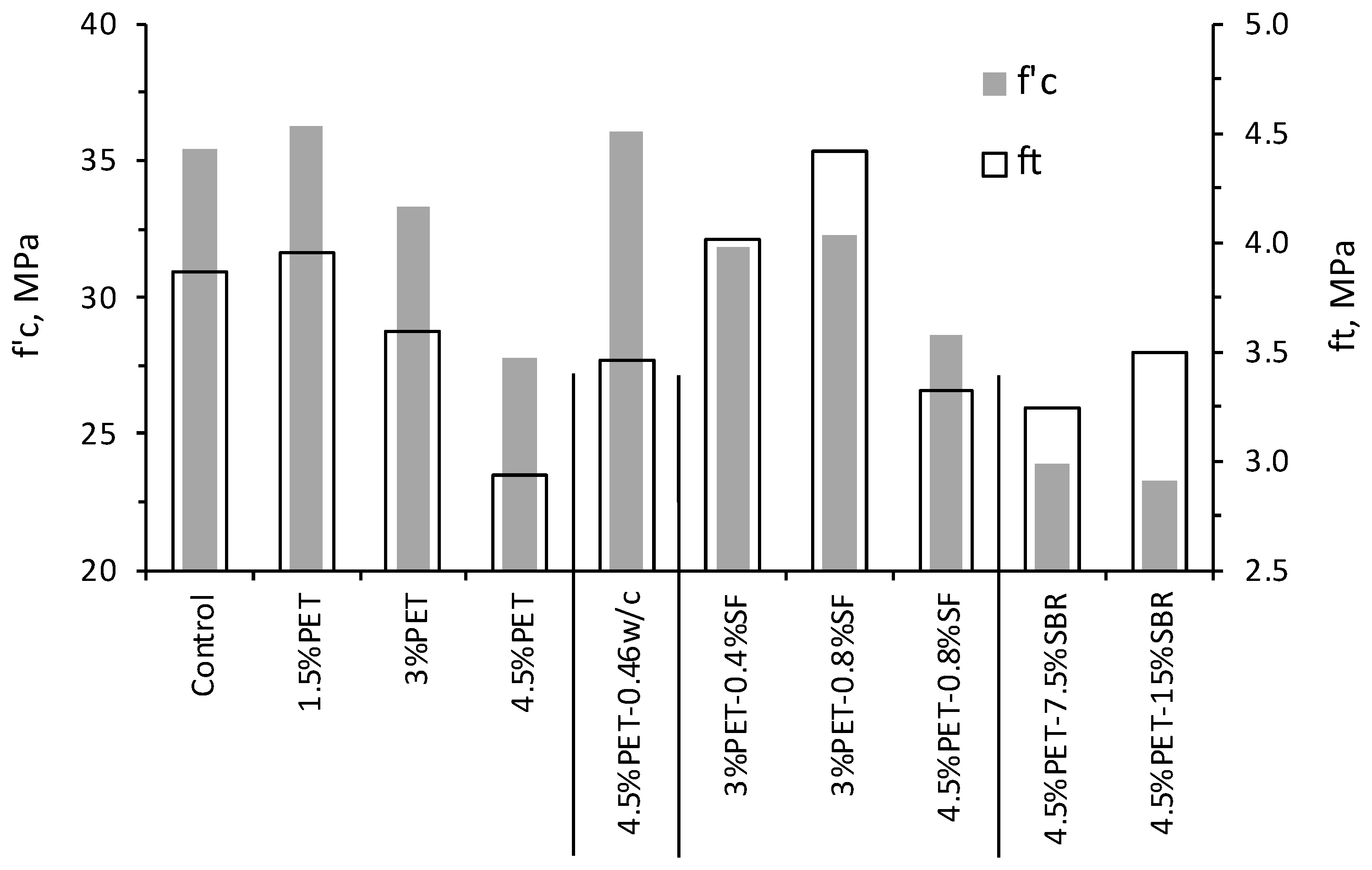
Figure 3 plots the f′c and ft responses for the investigated mixtures. At a relatively low PET rate of 1.5%, a slight improvement in strength was noticed, hinting that such additions could play a beneficial bridging role within the cementitious matrix [26,39]. The resulting f′c increased from 35.43 MPa for the control mix to 36.23 MPa for the 1.5% PET mix; the corresponding ft increased from 3.87 to 3.96 MPa, respectively. Nevertheless, the strength considerably decreased at 3% and 4.5% PET addition rates, given their lightweight nature which reduces the concrete density and weakens the characteristic strength of the aggregate skeleton. For example, the f′c dropped from 35.43 MPa for the control mix to 33.27 and 27.78 MPa when 3% or 4.5% PET shreds were respectively incorporated. The corresponding ft decreased from 3.87 to 3.59 and 2.94 MPa, respectively, while the concrete density varied from 2345 to 2305 and 2270 kg/m3, respectively. Zehil and Assaad [5] related the drop in ft to poor bonding between the plastic wastes and the cementitious matrix, thus weakening the resistance against crack propagation during loading. This was visually verified when inspecting the broken cylinders since the failure planes were clearly visible along the PET interfaces. A good relationship with correlation coefficient (R2) of 0.81 exists between f’c and density for all tested mixtures, as expressed in Equation (1).
f′c, MPa = 0.136 (Density, kg/m3) − 2824.3 R2 = 0.81
As shown in Figure 3, the reduction in w/c from 0.55 to 0.46 was efficient to compensate for the drop in strength due to 4.5% PET, which can naturally be attributed to a reduced matrix porosity and refined microstructure [36]. The corresponding f′c and ft reached 36.03 and 3.46 MPa, respectively. At a 3% PET rate, the decrease in ft responses was fully recovered by the incorporation of SF; hence, the ft reached 4.01 and 4.42 MPa for the 3%PET-0.4%SF and 3%PET-0.8%SF, respectively. This can be directly attributed to the presence of fibers that are known by their efficiency to delay the formation of cracks, or at least arrest their initial growth during tensile loading [18,37]. Nevertheless, despite the use of 0.8% SF, the loss in strength for the 4.5% PET-modified concrete was not recovered, suggesting that this could be the threshold rate incorporated in concrete mixtures. Hence, the corresponding f′c and ft were 28.59 and 3.32 MPa, respectively.
The addition of SBR differently affected the compression and tensile-related properties (Figure 3), which is consistent with current literature [27,29,35]. Hence, the drop in f′c can be attributed to the presence of surfactants as well as the elastic nature of the polymer films that weaken the resistance of the cement matrix to compression loading. In contrast, the ft gradually improved to 3.25 and 3.49 MPa for the 4.5%PET-7.5%SBR and 4.5%PET-15%SBR mixtures, respectively. Ohama [40] reported that weak tensile properties of cementitious materials can be greatly compensated by the incorporation of latexes, given that the coalesced polymer films can impede the initiation of cracks and strengthen the cement-aggregate interfacial transition zones (ITZs). Assaad and Khayat [35] suggested that the improved smoothness of latex-modified concrete can reduce the porosity of ITZs, thus creating a stronger bond by micro-mechanical interlocking mechanisms.
4.2. Flexural Strength of RC Beams Containing Stirrups
4.2.1. Crack Patterns
Typical crack patterns observed after failure for selected RC beams are illustrated in Figure 4. Three flexural cracks were initiated within the mid-span of the control beam after the cracking load, which then propagated in a vertical direction until failure. Further loading caused the yielding of tensile steel, while some inclined flexure-shear cracks were formed at about 45 degrees from the horizontal line. The 4.5% PET beam displayed similar crack patterns, but without inclined cracks. In fact, as the load increased, the flexural cracks became wider and unstable, which constituted the dominant failure mechanism. The biggest flexural crack opening after failure in the control beam was 0.87 mm at the extreme bottom, while reached 1.35 mm for the beam containing 4.5% PET.
The incorporation of steel fibers (i.e., 4.5%PET-0.8%SF) considerably altered the crack patterns. Hence, the number of flexural cracks reduced within the mid-span, while instead multiple bond and flexure-shear cracks were created (Figure 4). Many scholars attributed these crack patterns to the SF that restricts the propagation of cracks and transmits the tensile stresses to the surrounding concrete, thus releasing the energy to other locations and creating more cracks before failure. The biggest flexural crack opening at the extreme bottom was 0.44 mm.
4.2.2. Effect of PET on Load vs. Deflection Curves
Concurrent with existing literature, two distinct segments can be identified during the loading history of the control and PET-modified RC beams containing stirrups (Figure 5) [36]. The first segment is typically associated with the internal concrete/steel couple resistance to the applied load, while the second one reflects the yielding of tensile reinforcement with an almost horizontal load vs. deflection plateau [37,41]. This later segment is often accompanied by the crushing of concrete in the compression zone together with buckling of compression bars and/or fracture of stirrups. As shown in Figure 5, the stiffness in the load vs. deflection curves improved with PET additions. For example, the load that resulted at a 2-mm deflection increased from 48.5 kN for the control beam to 60.7 kN for the one incorporating 3% PET. This can be attributed to the PET particles that could have arrested the initiation of flexural cracks and reduced their propagation towards the compression zone, leading to increased stiffness of the load vs. deflection curves. The load reached 72.9 kN for the 4.5%PET-0.46w/c beam, which can be related to reduced w/c that refines the concrete porosity and strengthens its skeleton.
Table 3 summarizes the maximum load (Pmax) and corresponding deflection (δmax) at failure for all tested beams. Regardless of PET additions, the Pmax recorded for the various RC beams remained within the repeatability of testing, varying within 6.5% (i.e., 92 ± 6 kN). Knowing that the RC beams are designed to be under-reinforced (i.e., the steel ratio is 1.21%), this reflects that the concrete mix design has no measurable effect on the beam’s ultimate capacity once the yielding of reinforcing bars has started. In other words, this indicates that the flexural strength of RC beams does not degrade with PET incorporation, since the behavior of such beams is mainly governed by the yielding of tensile steel.
4.2.3. Comparison with ACI 318-19 Design Model for Flexural Strength
The theoretical load (PACI) values determined using the nominal moment (Mn) proposed by the ACI 318-19 [42] design model for RC beams are summarized in Table 3. The Mn is expressed in Equation (2) as follows:
where As equals 226 mm2 (i.e., the cross-sectional area of flexural steel) and a is the depth of the equivalent rectangular stress block. The Pmax/PACI ratio increased from 0.94 for the control RC beam prepared without PET to 1.05 for the beam containing 3% PET. The highest Pmax/PACI ratio of 1.08 corresponded to the PET-modified beams containing 0.4% SF or prepared with reduced w/c.
4.3. Shear Strength of RC Beams without Stirrups
4.3.1. Crack Patterns
Generally, the shear failure of RC beams is sudden, with little or no advanced warning [36]; it mainly occurs in the high-shear regions near the supports in the form of diagonal tension cracks, bond splitting, and/or the crushing of the compression strut. As shown in Figure 6, the control beam failed due to one diagonal shear crack inclined at about 45 degrees from the horizontal axis; the maximum crack opening was 0.82 mm. The same crack patterns occurred for the 4.5%PET beam, except that a bigger crack opening of 2.3 mm was formed, hinting at a weaker aggregate interlock mechanism. Earlier studies showed that the reduced concrete strength coupled with poor PET/aggregate interfacial bonding could alleviate the shear transfer mechanism along the diagonal crack surfaces, leading to bigger cracks that constitute the dominant feature of the beam’s failure.
The reduction in w/c or addition of SF increased the number of diagonal cracks and caused their size to become finer (Figure 6). In the case of 4.5%PET-0.46w/c concrete, such behavior can be attributed to a higher aggregate interlock mechanism along the diagonal cracks as well as stronger dowel action along the longitudinal reinforcement, due to a refined matrix microstructure [36,41]. The incorporation of SF increased the number of shear cracks, just like the patterns noticed in Figure 4 for the beams configured for flexural strength testing.
4.3.2. Load vs. Deflection Curves for PET-Modified Beams
Figure 7 plots the load vs. deflection curves for the control and PET-modified RC beams without stirrups. All curves varied similarly at the initial stages of loading until reaching the ultimate load (Pmax) that is directly affected by the PET rate. Table 4 summarizes the first diagonal cracking load (Vcrack) observed during RC beam testing along with the relevant characteristics deducted from the load vs. deflection curves, including Pmax, corresponding deflection (δmax), and ultimate shear load (Vu = Pmax/2).
As shown in Figure 8, the Pmax of 59.13 kN recorded for the control beam increased to 62.4 and 74.54 kN when 1.5% or 3% PET are respectively incorporated, and then dropped down to 55.97 kN at a higher rate of 4.5%. The corresponding δmax increased from 2.25 mm for the control beam to 2.88 mm for the 3% PET beam but dropped to 1.95 mm for the 4.5% PET beam. Generally, the shear transfer in RC beams without stirrups mainly arises from three components, including the aggregate interlock along the diagonal fractured surface, the dowel action of longitudinal reinforcement, and the contribution of the uncracked compression zone [26,36,41]. The aggregate interlock is particularly influential and believed to transfer up to 50% of the applied shear force [36]. The incorporation of relatively low PET rates appears to strengthen the aggregate interlock component through increased internal friction within the concrete skeleton, leading to higher shear resistance. This phenomenon, however, does not persist at an increased PET rate of 4.5%, which can be attributed to the significant decrease in the concrete density and strength. Additionally, the increased concentration of waste plastics could have altered the bonding with the cement matrix, which reduced the concrete frictional resistance along the developed shear cracks [37].
4.3.3. Effect of Concrete Modification
Reduced w/c—Despite the relatively high PET rate of 4.5%, the effect of reducing w/c from 0.55 to 0.46 seems efficient to increase the stiffness in the pre-peak region of the load vs. deflection curves, and fully reinstate the shear resistance of the RC beams (Figure 9). Hence, Vcrack remarkably increased from 48.5 to 57 kN for the control and 4.5%PET-0.46w/c beams, respectively, which can be attributed to the increased concrete strength (such as f′c and ft) that promotes higher aggregate interlock. The corresponding Pmax varied from 59.13 to 62.84 kN, respectively. It is worth noting that the reduced bleeding (due to lower w/c) may have improved the dowel action of longitudinal reinforcement [19,20,43], which helped compensate for the drop in shear strength due to the 4.5% PET. Practically, this implies that the w/c reduction is a viable solution to recover the performance of RC beams containing such a relatively high 4.5% PET rate.
Effect of steel fibers—The Pmax of 74.54 kN recorded for the 3% PET beam significantly increased to 88.67 and 106.11 kN when 0.4% or 0.8% SF are respectively incorporated (Figure 8). This can be directly attributed to the fiber bridging phenomenon that reduces the initiation of fissures during loading and promotes higher aggregate interlock and shear resistance along the developed cracks. The corresponding δmax increased from 2.88 mm for the SF-free concrete to 4.11 and 4.7 mm with 0.4% or 0.8% SF additions, respectively, reflecting a higher ductility and capacity to sustain additional loads after the initiation of the diagonal cracks. Such results are in agreement with published literature [11,44,45], revealing the benefits of SF to mitigate the negative effect of plastic wastes on the concrete structural properties, including the bond to embedded steel reinforcement.
As shown in the load vs. deflection curves (Figure 9), the incorporation of 0.8% SF was efficient to fully restore the shear strength of the RC beam containing 4.5% PET. Hence, Vcrack was recorded at 56.5 kN (vs. 48.5 kN for the control beam), while the Pmax and δmax increased from 59.13 to 69.71 kN and from 2.25 to 2.69 mm, respectively. It should be noted that a good relationship with R2 of 0.87 exists between Pmax and δmax for all tested beams, as shown in Figure 10.
Effect of SBR—The Pmax increased from 55.97 kN for the beam containing 4.5% PET to 60 and 69.37 kN when 7.5% or 15% SBR polymers are respectively introduced (Figure 8 and Figure 9). The corresponding δmax varied from 1.95 to 2.97 and 2.4 mm, respectively. Many scholars attributed this improvement to the presence of polymers that coalesce and fuse into continuous close-packed films to enhance the bonding along the PET/cement matrix surfaces [27,40]. Moreso, the bond to embedded steel bars improves with SBR additions [28], which strengthens the dowel action and densifies the interfaces along the longitudinal reinforcement due to active polymer-cement co-matrices developed around the steel ribs. Just like the previous alternatives, this reveals that the bonding agents can be used to mitigate the detrimental effect of plastic wastes on the structural properties of RC beams.
A moderate relationship with R2 of 0.55 exists between Pmax and ft responses (Figure 11), reflecting a relatively close nature between the tensile vs. shear strength properties. Yet, the relationship substantially deteriorates when the f′c responses are used (i.e., R2 becomes less than 0.1), mostly giving the opposing effects of SF and SBR on the compression vs. shear strengths.
4.3.4. Comparison with ACI 318-19 Design Model for Shear Strength
The ultimate shear load (Vu) values determined experimentally are compared with the ACI 318-19 [42] design provisions for the shear strength (VACI) of RC beams without stirrups. The VACI is expressed as:
where b and d refer to the beam width (=150 mm) and effective depth (=125 mm), respectively. The is a reduction factor that accounts for lightweight concrete; it is taken equal to 1.0 since the density of all mixtures was higher than 1850 kg/m3 [42]. The is the longitudinal flexural reinforcement ratio, while Vf and Mf are the factored shear force and moment, respectively, at the specified section. Table 4 summarizes the ACI design shear strengths for all tested RC beams and the resulting Vu/VACI. As can be seen, the VACI values are quite conservative, leading to Vu/VACI values hovering from 1.43 to 2.66.
5. Conclusions
This paper assesses the feasibility of different concrete mix design alternatives that could be used to reinstate the flexural and shear strength properties of RC beams containing PET waste inclusions. The validation of test results using real-scale beams measuring 3.2 m long is presented in a follow-up publication. Such data can be of interest to promote the use of post-consumer plastics in medium-to-high strength concrete grades in structural applications. Based on the foregoing, the following conclusions can be warranted:
- The hardened properties (i.e., f′c and ft) are degraded when 3% or 4.5% PET are incorporated in the concrete, given their weak and light characteristic natures compared to aggregate particles. The drop in ft was related to poor bonding between the PET and cement matrix.
- The reduction in w/c from 0.55 to 0.46 was efficient to compensate for the drop in f′c and ft due to 4.5% PET additions, which was attributed to a reduced matrix porosity and refined concrete microstructure. Nevertheless, the loss in strength could not be recovered, despite the incorporation of 0.8% SF or 15% SBR.
- The use of 3% PET improved the stiffness of the load vs. deflection curves determined for RC beams containing stirrups, which was attributed to those particles that could have arrested the initiation of flexural cracks and reduced their propagation towards the compression zone. The same tendency was noticed when reducing w/c or incorporating SF or SBR in the 4.5% PET concrete.
- The flexural strength of RC beams does not degrade with 3% or 4.5% PET inclusions, since the behavior of such under-reinforced beams is mainly governed by the yielding of tensile steel. The ultimate load remained within the repeatability of testing (i.e., 92 ± 6 kN).
- The shear strength of RC beams without stirrups improved when 1.5% or 3% PET was incorporated in the concrete mixture, which was attributed to a higher aggregate interlock mechanism. However, the shear strength dropped at a higher PET rate of 4.5%, given the decrease in the concrete density and strength.
- The effect of reducing w/c from 0.55 to 0.46 was efficient to fully reinstate the shear resistance of 4.5% PET-modified beams without stirrups. Moreso, the incorporation of 0.8% SF, by volume, or 15% SBR, by mixing water, seems to be a viable solution to recover the performance of RC beams containing such a relatively high 4.5% PET rate.
- The ACI 318-19 design model for shear strength of RC beams without stirrups is quite conservative; the Vu/VACI values varied from 1.43 to 2.66.
Author Contributions
Conceptualization, J.J.A., M.K. and J.K.; methodology, J.J.A. and J.K.; software, M.K.; validation, J.J.A., M.K. and J.K.; formal analysis, J.J.A. and J.K.; investigation, J.J.A. and M.K.; resources, J.J.A.; data curation, J.J.A. and M.K.; writing—original draft preparation, J.J.A. and M.K.; writing—review and editing, J.J.A. and J.K.; visualization, J.J.A.; supervision, J.J.A.; project administration, J.J.A.; funding acquisition, J.J.A. All authors have read and agreed to the published version of the manuscript.
Funding
This research received no external funding.
Institutional Review Board Statement
Not applicable.
Informed Consent Statement
Not applicable.
Conflicts of Interest
The authors declare that there is no conflict of interest regarding the publication of this paper.
References
- United Nation. COP26: The Negotiations Explained. In Proceedings of the 26th UN Climate Change Conference UK 2021, Glasgow, UK, 31 October–13 November 2021. [Google Scholar]
- Tsai, W.T. Environmental policy for the restriction on the use of plastic products in Taiwan: Regulatory measures, implementation status and COVID-19’s impacts on plastic products recycling. Environments 2022, 9, 7. [Google Scholar] [CrossRef]
- Singh, N.; Hui, D.; Singh, R.; Ahuja, I.P.S.; Feo, L.; Fraternali, F. Recycling of plastic solid waste: A state of art review and future applications. Compos. Part B Eng. 2017, 115, 409–422. [Google Scholar] [CrossRef]
- Siddique, S.; Khatib, J.; Kaur, I. Use of recycled plastic in concrete: A review. Waste Manag. 2008, 28, 1835–1852. [Google Scholar] [CrossRef] [PubMed]
- Zehil, G.P.; Assaad, J.J. Feasibility of concrete mixtures containing cross-linked polyethylene waste materials. Constr. Build. Mater. 2019, 226, 1–10. [Google Scholar] [CrossRef]
- Khatib, J.M.; Jahami, A.; Elkordi, A.; Abdelgader, H.; Sonebi, M. Structural assessment of reinforced concrete beams incorporating waste plastic straws. Environments 2020, 7, 96. [Google Scholar] [CrossRef]
- Choi, Y.W.; Moon, D.J.; Kim, Y.J.; Lachemi, M. Characteristics of mortar and concrete containing fine aggregate manufactured from recycled waste polyethylene terephthalate bottles. Constr. Build. Mater. 2009, 23, 2829–2835. [Google Scholar] [CrossRef]
- Assaad, J.J.; Daou, A.; Daou, Y. Bond properties of polymer-modified lightweight self-consolidating concrete containing expanded polystyrene. Adv. Civ. Eng. Mater. 2019, 8, 558–572. [Google Scholar] [CrossRef]
- Belmokaddem, M.; Mahi, A.; Senhadji, Y.; Pekmezci, B.Y. Mechanical and physical properties and morphology of concrete containing plastic waste as aggregate. Constr. Build. Mater. 2020, 257, 119559. [Google Scholar] [CrossRef]
- Nur Hanis, Z.; Gani, P.; Chuan, N.C.; Uvarajan, T. Utilisation of plastic waste as aggregate in construction materials: A review. Constr. Build. Mater. 2021, 296, 123669. [Google Scholar] [CrossRef]
- Saikia, N.; de Brito, J. Mechanical properties and abrasion behaviour of concrete containing shredded PET bottle waste as a partial substitution of natural aggregate. Constr. Build. Mater. 2014, 52, 236–244. [Google Scholar] [CrossRef]
- Mahdi, N.; Reza, M. Post-fire flexural behavior of functionally graded fiber-reinforced concrete containing rubber. Comput. Concr. 2021, 27, 417–435. [Google Scholar] [CrossRef]
- Jawad, F.; Adarsha, C.Y.; Raghavendra, B.C.; Udayashankar, K.; Natarajan, K. Structural behavior of concrete beams and columns reinforced with waste plastic incorporated GFRP (WPGFRP) rebars. J. Build. Eng. 2019, 23, 172–184. [Google Scholar] [CrossRef]
- Mohammed, A.A. Flexural behavior and analysis of reinforced concrete beams made of recycled PET waste concrete. Constr. Build. Mater. 2017, 155, 593–604. [Google Scholar] [CrossRef]
- Mohammed, A.A.; Faqe Rahim, A.A. Experimental behavior and analysis of high strength concrete beams reinforced with PET waste fiber. Constr. Build. Mater. 2020, 244, 118350. [Google Scholar] [CrossRef]
- Adnan, H.M.; Dawood, A.O. Strength behavior of reinforced concrete beam using re-cycle of PET wastes as synthetic fibers. Case Stud. Constr. Mater. 2020, 13, e00367. [Google Scholar] [CrossRef]
- Shahjalal, M.; Islam, K.; Rahman, J.; Ahmed, K.S.; Karim, M.R.; Billah, A.H.M.M. Flexural response of fiber reinforced concrete beams with waste tires rubber and recycled aggregate. J. Clean. Prod. 2021, 278, 123842. [Google Scholar] [CrossRef]
- Dawood, A.O.; Khazraji, H.; Falih, R.S. Physical and mechanical properties of concrete containing PET wastes as a partial replacement for fine aggregates. Case Stud. Constr. Mater. 2021, 14, e00482. [Google Scholar] [CrossRef]
- Thorneycroft, J.; Orr, J.; Savoikar, P.; Ball, R.J. Performance of structural concrete with recycled plastic waste as a partial replacement for sand. Constr. Build. Mater. 2018, 161, 63–69. [Google Scholar] [CrossRef]
- Assaad, J.J.; Khatib, J.M.; Ghanem, R. Bond to bar reinforcement of PET-modified concrete containing natural or recycled coarse aggregates. Environments 2022, 9, 8. [Google Scholar] [CrossRef]
- ASTM C33/C33 M-16; Standard Specification for Concrete Aggregates. Annual Book of ASTM Standards: West Conshohocken, PA, USA, 2016.
- ASTM C496/C496 M-19; Standard Specification for Chemical Admixtures for Concrete. Annual Book of ASTM Standards: West Conshohocken, PA, USA, 2019.
- ASTM A615/A615 M-20; Standard Specification for Deformed and Plain Carbon-Steel Bars for Concrete Reinforcement. Annual Book of ASTM Standards: West Conshohocken, PA, USA, 2020.
- EFNARC. The European Guidelines for Self-Compacting Concrete. May 2005, p. 63. Available online: http://www.efnarc.org/pdf/SCCGuidelinesMay2005.pdf (accessed on 31 May 2005).
- Khayat, K.H.; Assaad, J.J. Measurement systems for determining formwork pressure of highly flowable concrete. Mater. Struct. 2008, 41, 37–46. [Google Scholar] [CrossRef]
- Raad, D.; Assaad, J.J. Structural properties of fiber-reinforced concrete containing thermosetting polymer plastic wastes. J. Sustain. Cem.-Based Mater. 2021. [Google Scholar] [CrossRef]
- ACI 548.3R-03; Polymer-Modified Concrete. American Concrete Institute: Farmington Hills, MI, USA, 2003; 40p.
- Wang, Z.J.; Wang, R.; Cheng, Y.B. Mechanical properties and microstructures of cement mortar modified with styrene-butadiene polymer emulsion. In Advanced Materials Research; Trans Tech Publications, Ltd.: Zürich, Switzerland, 2011. [Google Scholar]
- Assaad, J.J.; El Mir, A. Durability of polymer-modified lightweight flowable concrete made using expanded polystyrene. Constr. Build. Mater. 2020, 249, 118764. [Google Scholar] [CrossRef]
- ASTM C143/C143M-15a; Standard Test Method for Slump of Hydraulic-Cement Concrete. Annual Book of ASTM Standards: West Conshohocken, PA, USA, 2015.
- ASTM C231/C231M-17a; Standard Test Method for Air Content of Freshly Mixed Concrete by the Pressure Method. ASTM International: West Conshohocken, PA, USA, 2017.
- ASTM C642-13; Standard Test Method for Density, Absorption, and Voids in Hardened Concrete. Annual Book of ASTM Standards: West Conshohocken, PA, USA, 2013.
- ASTM C39/C39M-18; Standard Test Method for Compressive Strength of Cylindrical Concrete Specimens. Annual Book of ASTM Standards: West Conshohocken, PA, USA, 2018.
- ASTM C496/C496M–17; Standard Test Method for Splitting Tensile Strength of Cylindrical Concrete Specimens. Annual Book of ASTM Standards: West Conshohocken, PA, USA, 2017.
- Assaad, J.J.; Khayat, K.H. Rheology of fiber-reinforced high-strength grout modified with polymer latexes. ACI Mater. J. 2021, 118, 49–60. [Google Scholar] [CrossRef]
- MacGregor, J.G.; Wight, J.K. Reinforced Concrete: Mechanics and Design; Prentice Hall South Asia-Pearson Education: Singapore, 2011. [Google Scholar]
- Jabbour, R.; Assaad, J.J.; Hamad, B. Cost-to-performance assessment of polyvinyl alcohol fibers in concrete structures. Mech. Adv. Mater. Struct. 2021, 1–12. [Google Scholar] [CrossRef]
- Machaka, M.; Elkordi, A.; Ghanem, H.; Khatib, J.; Baalbaki, O. Selected properties of concrete containing palm fibers. Acad. J. Civ. Eng. 2019, 37, 279–286. [Google Scholar] [CrossRef]
- Jahami, A.; Khatib, J.; Baalbaki, O.; Sonebi, M. Prediction of deflection in reinforced concrete beams containing plastic waste. Acad. J. Civ. Eng. 2019, 37, 551–555. [Google Scholar] [CrossRef]
- Ohama, Y. Handbook of Polymer-Modified Concrete and Mortars: Properties and Process Technology; Noyes Publications: Saddle River, NJ, USA, 1995. [Google Scholar]
- Kwak, Y.K.; Eberhard, M.O.; Kim, W.S.; Kim, J. Shear strength of steel fiber-reinforced concrete beams without stirrups. ACI Struct. J. 2002, 99, 530–538. [Google Scholar]
- ACI Committee 318; Building Code Requirements for Structural Concrete (ACI 318M-19) and Commentary (ACI 318RM-19). American Concrete Institute: Farmington Hills, MI, USA, 2019.
- Assaad, J.J.; Khayat, K.H. Effect of casting rate and concrete temperature on formwork pressure of self-consolidating concrete. Mater. Struct. 2006, 39, 333–341. [Google Scholar] [CrossRef]
- Kachouh, N.; El-Maaddawy, T.; El-Hassan, H.; El-Ariss, B. Shear response of recycled aggregates concrete deep beams containing steel fibers and web openings. Sustainability 2022, 14, 945. [Google Scholar] [CrossRef]
- Kachouh, N.; El-Maaddawy, T.; El-Hassan, H.; El-Ariss, B. Shear behavior of steel-fiber reinforced recycled aggregate concrete deep beams. Buildings 2021, 11, 423. [Google Scholar] [CrossRef]
Figure 1.
Photo for the shredded PET waste particles.

Figure 2.
Configuration of RC beams for flexural and shear strength testing.

Figure 3.
Effect of PET additions on strength of hardened concrete.

Figure 4.
Crack patterns for selected beams after failure (i.e., flexure testing).

Figure 5.
Load vs. mid-span deflection curves for RC beams (i.e., flexure testing).

Figure 6.
Crack patterns for the control and 4.5% PET-modified beams (i.e., shear testing).

Figure 7.
Load vs. mid-span deflection curves for the control and PET-modified RC beams.

Figure 8.
Effect of concrete modification on Pmax and δmax for RC beams without stirrups.

Figure 9.
Effect of concrete modification on the load vs. mid-span deflection curves for the 4.5% PET-modified RC beams (i.e., shear testing).
Figure 9.
Effect of concrete modification on the load vs. mid-span deflection curves for the 4.5% PET-modified RC beams (i.e., shear testing).

Figure 10.
Relationship between Pmax and δmax responses for RC beams (i.e., shear testing).

Figure 11.
Relationship between Pmax determined on RC beams without stirrups and ft responses.


Table 1.
Typical PET-modified concrete proportions.
| Control | 1.5%PET | 3%PET | 4.5%PET | 4.5%PET-0.46w/c | |
|---|---|---|---|---|---|
| Cement, kg/m3 | 350 | 350 | 350 | 350 | 350 |
| Water, kg/m3 | 193 | 193 | 193 | 193 | 160 |
| w/c | 0.55 | 0.55 | 0.55 | 0.55 | 0.46 |
| Fine aggregate, kg/m3 | 810 | 790 | 770 | 750 | 800 |
| Coarse aggregate, kg/m3 | 990 | 980 | 960 | 940 | 980 |
| PET, % by volume | 0 | 1.5 | 3 | 4.5 | 4.5 |
Table 2.
HRWR demand, density, and hardened properties for PET-modified concrete.
| HRWR, % of Cement Mass | Slump, mm | Air Content, % | Density, kg/m3 | f′c, MPa | ft, MPa | |
|---|---|---|---|---|---|---|
| Control | 1.52 | 200 | 2.7 | 2345 | 35.43 | 3.87 |
| 1.5%PET | 1.57 | 205 | n/a | 2340 | 36.23 | 3.96 |
| 3%PET | 1.65 | 180 | 2.5 | 2305 | 33.27 | 3.59 |
| 4.5%PET | 2.09 | 200 | 3.1 | 2270 | 27.78 | 2.94 |
| 4.5%PET-0.46w/c | 3.29 | 190 | 2.8 | 2310 | 36.03 | 3.46 |
| 3%PET-0.4%SF | 1.77 | 200 | n/a | 2295 | 31.85 | 4.01 |
| 3%PET-0.8%SF | 1.76 | 185 | 3.2 | 2315 | 32.28 | 4.42 |
| 4.5%PET-0.8%SF | 2.19 | 205 | n/a | 2265 | 28.59 | 3.32 |
| 4.5%PET-7.5%SBR | 1.9 | 200 | 3.3 | 2270 | 23.9 | 3.25 |
| 4.5%PET-15%SBR | 1.74 | 210 | n/a | 2255 | 23.29 | 3.49 |
Table 3.
Flexural strength properties of investigated RC beams.
| Pmax, kN | δmax, mm | PACI, kN | Pmax/PACI | |
|---|---|---|---|---|
| Control | 86.73 | 4.47 | 92.44 | 0.94 |
| 3%PET | 96.04 | 3.56 | 91.76 | 1.05 |
| 4.5%PET-0.46w/c | 99.79 | 2.78 | 92.61 | 1.08 |
| 3%PET-0.4%SF | 98.25 | 3.17 | 92.25 | 1.08 |
| 4.5%PET-15%SBR | 89.16 | 3.92 | 86.96 | 1.03 |
Table 4.
Shear strength properties of investigated RC beams.
| Vcrack, kN | Pmax, kN | Vu, kN | δmax, mm | VACI, kN | Vu/VACI | |
|---|---|---|---|---|---|---|
| Control | 48.5 | 59.13 | 29.57 | 2.25 | 20.7 | 1.43 |
| 1.5%PET | 50 | 62.4 | 31.2 | 2.32 | 20.9 | 1.49 |
| 3%PET | 55.5 | 74.54 | 37.27 | 2.88 | 20.2 | 1.85 |
| 4.5%PET | 43.5 | 55.97 | 27.99 | 1.95 | 18.7 | 1.5 |
| 4.5%PET-0.46w/c | 57 | 62.84 | 31.42 | 2.08 | 20.9 | 1.51 |
| 3%PET-0.4%SF | 74.5 | 88.67 | 44.34 | 4.11 | 19.8 | 2.24 |
| 3%PET-0.8%SF | 88.5 | 106.11 | 53.06 | 4.7 | 19.9 | 2.66 |
| 4.5%PET-0.8%SF | 56.5 | 69.71 | 34.86 | 2.69 | 18.9 | 1.84 |
| 4.5%PET-7.5%SBR | 51.5 | 60 | 30 | 2.97 | 17.6 | 1.71 |
| 4.5%PET-15%SBR | 54 | 69.37 | 34.69 | 2.4 | 17.4 | 1.99 |
Publisher’s Note: MDPI stays neutral with regard to jurisdictional claims in published maps and institutional affiliations. |
© 2022 by the authors. Licensee MDPI, Basel, Switzerland. This article is an open access article distributed under the terms and conditions of the Creative Commons Attribution (CC BY) license (https://creativecommons.org/licenses/by/4.0/).
Share and Cite
MDPI and ACS Style
Assaad, J.J.; Khalil, M.; Khatib, J. Alternatives to Enhance the Structural Performance of PET-Modified Reinforced Concrete Beams. Environments 2022, 9, 37. https://doi.org/10.3390/environments9030037
AMA Style
Assaad JJ, Khalil M, Khatib J. Alternatives to Enhance the Structural Performance of PET-Modified Reinforced Concrete Beams. Environments. 2022; 9(3):37. https://doi.org/10.3390/environments9030037
Chicago/Turabian StyleAssaad, Joseph J., Mario Khalil, and Jamal Khatib. 2022. "Alternatives to Enhance the Structural Performance of PET-Modified Reinforced Concrete Beams" Environments 9, no. 3: 37. https://doi.org/10.3390/environments9030037
Note that from the first issue of 2016, this journal uses article numbers instead of page numbers. See further details here.