Implementation of an Obstacle Recognition System for the Blind


Department of IT Engineering, Sookmyung Women’s University, 100, Cheongpa-ro 47-gil, Yongsan-gu, Seoul 04310, Korea
*
Author to whom correspondence should be addressed.
Appl. Sci. 2020, 10(1), 282; https://doi.org/10.3390/app10010282
Submission received: 31 October 2019
/
Revised: 24 December 2019
/
Accepted: 28 December 2019
/
Published: 30 December 2019
(This article belongs to the Special Issue Intelligent System Innovation)
Abstract
:The blind encounter commuting risks, such as failing to recognize and avoid obstacles while walking, but protective support systems are lacking. Acoustic signals at crosswalk lights are activated by button or remote control; however, these signals are difficult to operate and not always available (i.e., broken). Bollards are posts installed for pedestrian safety, but they can create dangerous situations in that the blind cannot see them. Therefore, we proposed an obstacle recognition system to assist the blind in walking safely outdoors; this system can recognize and guide the blind through two obstacles (crosswalk lights and bollards) with image training from the Google Object Detection application program interface (API) based on TensorFlow. The recognized results notify the blind through voice guidance playback in real time. The single shot multibox detector (SSD) MobileNet and faster region-convolutional neural network (R-CNN) models were applied to evaluate the obstacle recognition system; the latter model demonstrated better performance. Crosswalk lights were evaluated and found to perform better during the day than night. They were also analyzed to determine if a client could cross at a crosswalk, while the locations of bollards were analyzed by algorithms to guide the client by voice guidance.
1. Introduction
Many people with disabilities have some difficulty walking unaided and are exposed to various traffic accident risks. They are often classified as mobility impaired. Disability protection areas are necessary to protect the disabled from danger while walking; however, according to data in Seoul, only seven of the 631 disabled facilities have been designed as disability protection areas [1]. The lack of safeguards for people with disabilities can deprive them of many positive opportunities, including walking independently. As the population increases, the number of blind and visually impaired people also increases. Researchers have predicted that the number of people with a visual impairment or blindness will increase from 38.5 million in 2020 to more than 115 million by 2050 [2]. Among the various types of disabilities, we took into consideration the walking safety of the blind and visually impaired. We focused particularly on problems that could arise while walking outside.
The blind can choose from various methods that can help guide them while walking outdoors. One way is the utilization of guide dogs. Guide dogs are trained by professional trainers for an average of two years until they are skilled enough to safely guide the blind. Some blind people prefer to buy a guide dog owing to its familiar character. However, people with an aversion to animals may not want to utilize a guide dog. Moreover, if the blind or their family members have a health problem, such as an allergy to dogs, they cannot choose this method of assistance. Additionally, it costs money to buy and support a dog, and not everyone can afford such an expense. Furthermore, there are not enough guide dogs available to assist the blind; therefore, there needs to be alternative ways to support the visually impaired and blind.
The blind must also consider the various obstacles they will encounter while walking outdoors. Theoretically, they can use acoustic signals when they want to cross streets independently at crosswalks, however, the emplacement rate of acoustic signals is only 57% [3]. People with disabilities can operate the acoustic signals directly by pressing a button or using a device, such as a remote control. However, the acoustic signal button is installed in the light pole near a crosswalk, so it cannot be operated if it is inaccessible to the blind or if it is broken.
Another obstacle that interferes with safety while walking is the use of bollards, which are short posts. Bollards are installed to keep pedestrians safe by preventing cars and other dangerous objects from entering pedestrian pathways. However, they are installed in the middle of sidewalks, which can pose a big danger to the blind who cannot see them. There have also been instances where non-visually impaired people have collided with bollards and fallen because the bollards were not properly marked.
In this study, we implemented a system that recognizes crosswalk lights and bollards. We used images of crosswalk lights and bollards to detect actual crosswalk lights and bollards to safely guide the blind. An engine for assessing whether images were considered to be obstacles was implemented by retraining the existing object detection models [4,5] of deep learning. After acknowledging the presence of a crosswalk light, the module that detects a crosswalk light determines whether it is safe for the blind to cross or not and directs them by voice [6]. The bollard recognition module informs the blind where the obstacle is by using the faster region-convolutional neural network (R-CNN) model to recognize it. Our system enables real time image recognition and guidance with Raspberry Pi or an Android application. Here, we introduce our system and how to implement it. We also provide its performance evaluation. Using this system, we could provide a safe outdoor walking environment for the blind.
2. Related Works
The avoidance of obstacles for blind people has traditionally centered around the use of electronic travel aids (ETA), as documented in previous research [7,8,9]. The ETA approach for the blind requires the use of portable-wearable devices containing many electronic sensors that are expensive to manufacture.
Recently, a study proposed a new navigation aid for the blind that was inexpensive to manufacture and easy to use. The study described a problem encountered by the blind in that they could not easily detect obstacles above their waists or a few feet away [10]. Therefore, a navigation aid system for the blind was suggested that could detect the surrounding environment via several types of sensors. This system consisted of sonar sensors situated on the shoulder for detecting obstacles in front of the blind person, a vibrator on an arm for vibro-tactile feedback, and an ultrasonic cane for detecting obstacles on the ground. Detection of the obstacles was controlled by a central micro-controller that connected all the components. The system allowed a person to navigate a 100 m route with some obstacles; however, the system needed a very clean testing environment with little noise. Furthermore, it could only detect the existence of an obstacle, but it could not identify the type of obstacle.
Later, an obstacle recognition system using radio-frequency identification (RFID) technology was proposed [11]. The system proposed a smart cane outfitted with a Braille display handle. This smart cane could read information provided by RFID tags that were installed in various places. The cane would then analyze the information and display it on the Braille display through the control of electro-mechanical switches. As a result, blind people were able to recognize obstacles via the Braille display. Ultimately, it was determined that the proposed system had several limitations for its adoption in the real world. First, the system did not discriminate between the types of obstacles a blind person could encounter. Additionally, the installation of RFID tags on every surrounding surface was virtually impossible. Even if the installation of RFID tags everywhere was possible to achieve, it would entail a massive cost, as determined by the cost analysis conducted during the study.
Herein, we proposed an enhanced obstacle recognition system based on the technology of image recognition in real time. Table 1 shows a comparison between the systems proposed in related works and the proposed system of this study. The navigation aid for the blind [10] and the obstacle recognition system using RFID [11] both used several sensors. The navigation aid required ultrasonic sensors to determine if obstacles were in front of the blind, while the obstacle recognition system using RFID required as many RFID tags as the number of obstacles present. Our proposed system does not necessitate the manufacture of anything, nor does it require that expensive equipment be worn. In addition, our proposed system made it possible to recognize an obstacle by using a video input device, namely, a single camera, rather than several types of sensor. It could also recognize the types of obstacles that were in front of the blind.
3. Obstacle Recognition Model and System Architecture
To recognize various obstacles, we used a Google Object Detection application program interface (API) [12] based on TensorFlow [13]. The API had various pre-trained object detection models, including single shot multibox detector (SSD) MobileNet and Faster R-CNN. These models could recognize 90 classes (e.g., cat, dog, car, bus). If we used the original pre-trained models, which were not specialized in obstacle data, we could not recognize any bollards or crosswalk lights. For this reason, the models needed to be customized using retraining. We collected obstacle data for bollards and crosswalk lights and retrained the models. The models were applied to the obstacle recognition module and recognized obstacles were learned in real time. According to the recognized results, the obstacles were input into the crosswalk discrimination module and the location calculation module, and a customized algorithm was applied. Each result of the algorithm was passed on to the client, and then, the client could monitor the location of a bollard and the state of the crosswalk light. The guidance was remarkably close to real time and was effective at keeping the client safe.
3.1. Obstacle Recognition Model
3.1.1. Data
We took photos of the crosswalk lights and bollards directly to collect data to train the obstacle recognition model. It was important to use obstacle images with various backgrounds in the training model. Therefore, crosswalk lights and bollards were photographed at various locations and times of day and night to obtain different backgrounds for the training data. In addition to the various backgrounds, it was also necessary to photograph the obstacles from several different angles.
Bollards have various standard specifications from city to city and look different even if they are the same size. We decided to collect images of the bollards near Sookmyung Women’s University. In the case of crosswalk lights, we collected images of both green and red lights. The various data was gathered not only during the day but the night as well. This was necessary for the ability to detect crosswalk lights even in the dark of night. Additionally, crosswalk lights have three types of lights (red, green, and flashing), so data was accumulated for each type. Therefore, we collected six types of data in total for crosswalk lights, using a combination of the two conditions (day and night) and the three types of lights (red, green, and flashing). Test data were also collected, with the same method as the training data, to confirm whether the trained model worked proficiently.
The data used to train the model required not only image data but also position information of obstacles within the image. The position data was saved as an extensible markup language (XML) data file by marking the coordinates of each obstacle within the image as a bounding box. The LabelImg tool [14], an image labeling utility program, was used to generate such data. This tool could store various output formats by adding boxes of objects in the images or videos. In this way, we have created approximately 6350 pairs of image data and position data for training and 1000 pairs, thus far, for test data.
3.1.2. Model
We used the Google Object Detection API to train the obstacle recognition model. It provided several pre-trained models utilizing common objects in context (COCO) data. We trained the SSD_MobileNet_v1_COCO and Faster_R-CNN_ResNet101_COCO models with the training data we collected. We chose to use those particular models for two main reasons. First, we chose them for their ability to run on little computing power. This meant that the obstacle recognition system could be applied to portable devices in the future; for example, on small computers, such as the Raspberry Pi or a smartphone. Second, other models, such as “You Only Look Once” (YOLO) [15], have a relatively little ability to detect small objects, which would be counterintuitive to our study. In any case, there were also differences between the two models used in our study. The SSD_MobileNet_v1_COCO-based SSD [4] had the advantage of not using much computing power, but its obstacle recognition accuracy was not high, while the Faster_R-CNN_ResNet101_COCO-based Faster R-CNN [5] had the advantage of being able to process more image features in less time, allowing for higher accuracy with regard to detecting obstacles. We compare the performances of the two models in Section 5.
The models could recognize 90 classes when using the current API checkpoint. Our objective was to have them recognize both bollards and crosswalk lights, so we had to train extensively with the use of our own data. For the additional training, the number of steps was 50,000. The batch size was 24, and the input image size was 500 × 500 pixels.
3.2. System Architecture
This section describes the system architecture (Figure 1) in which the system works. First, the Raspberry Pi was capable of streaming videos in real time. Streamed videos were imported to the server using a network module. These images were divided into 30 frames per second in the data processing. The obstacle recognition module was the main module in the system. It recognized obstacles in the images using an obstacle recognition module based on the retraining, and then it executed either the crosswalk discrimination module or location calculation module. Each of the divided images from the Raspberry Pi were input into the obstacle recognition model (Step 3, Figure 1) to recognize crosswalk lights and bollards. Images that were recognized as crosswalk lights were then input into the crosswalk discrimination module (Step 4).
The crosswalk discrimination module extracted only the position of the incoming crosswalk light images where the bounding box was drawn. We used the identification function [6] to identify red and green in the images. This function identified a value for each color, based on the threshold of whether it was red or green. The result of the color calculation was input into the crosswalk safety guidance algorithm. The algorithm analyzed 30 frames per second and finally produced results for none (as in no light was detected), and red, green, and flashing lights. The guidance results were passed to the Raspberry Pi via the network module. A voice guidance determination module in the Raspberry Pi used the guidance results to determine which voice was played. The module could play different voices corresponding to none, green light, red light, or flashing light. For example, when the system determined a green light, Raspberry Pi would voice, “Green light went on. You can cross the crosswalk.” If the object recognized was a bollard (Step 7), the image was input into the location finding module. This module calculated the correct location for a bollard using the coordinates of the bounding box where the bollard was present. The location result was passed to the Android app by the network module, which monitored the location of the obstacle. For instance, when a bollard was located to the left of a client, the Raspberry Pi would voice, “A bollard is on your left.”
4. Implementation
This section describes the details of implementation after the input images were recognized as either crosswalk lights or bollards. The algorithms were divided into crosswalk light discrimination, location finding, and client guidance. The crosswalk light discrimination was partially extended using an algorithm previously implemented [6]. We assumed that only one obstacle was recognized in an image.
4.1. Crosswalk Light Discrimination
Crosswalk light discrimination occurred after a crosswalk light was recognized as being as such in the obstacle recognition model (Figure 2). If the object was indeed recognized as a crosswalk light, the image was cut into the part corresponding to the crosswalk light, and then input into the algorithm as crop_img. In the process of lines 3–10, a red or green color could be detected using the detection color function. If a green color was detected, red_flag turned False, which meant that the client could not cross the crosswalk in the algorithm. In lines 11–13, if red_flag (set to True when red color was absent) and green_flag were True then result_flag became True. This indicated that the client could cross a road via the crosswalk. In contrast, if result_flag became False, it meant that the client must stop and wait.
After the green or red color was identified, the next step was to check if it was safe for the client to cross at the crosswalk, as determined by another algorithm (Figure 3). The input images received from the Raspberry Pi were divided into 30 frames per second. The algorithm then read the crop_img extracted from each frame and result_flag indicated the crosswalk light. A green count of result_per would be implemented if the green color was identified in the image, and a red count of result_per would be implemented if the red color was identified. The result_per of this algorithm was determined from four types of lights: none, red light, green light, and flashing light. The result was then passed to the Raspberry Pi client using a transmission control protocol (TCP) socket connection to play the voice guidance.
4.2. Location Finding
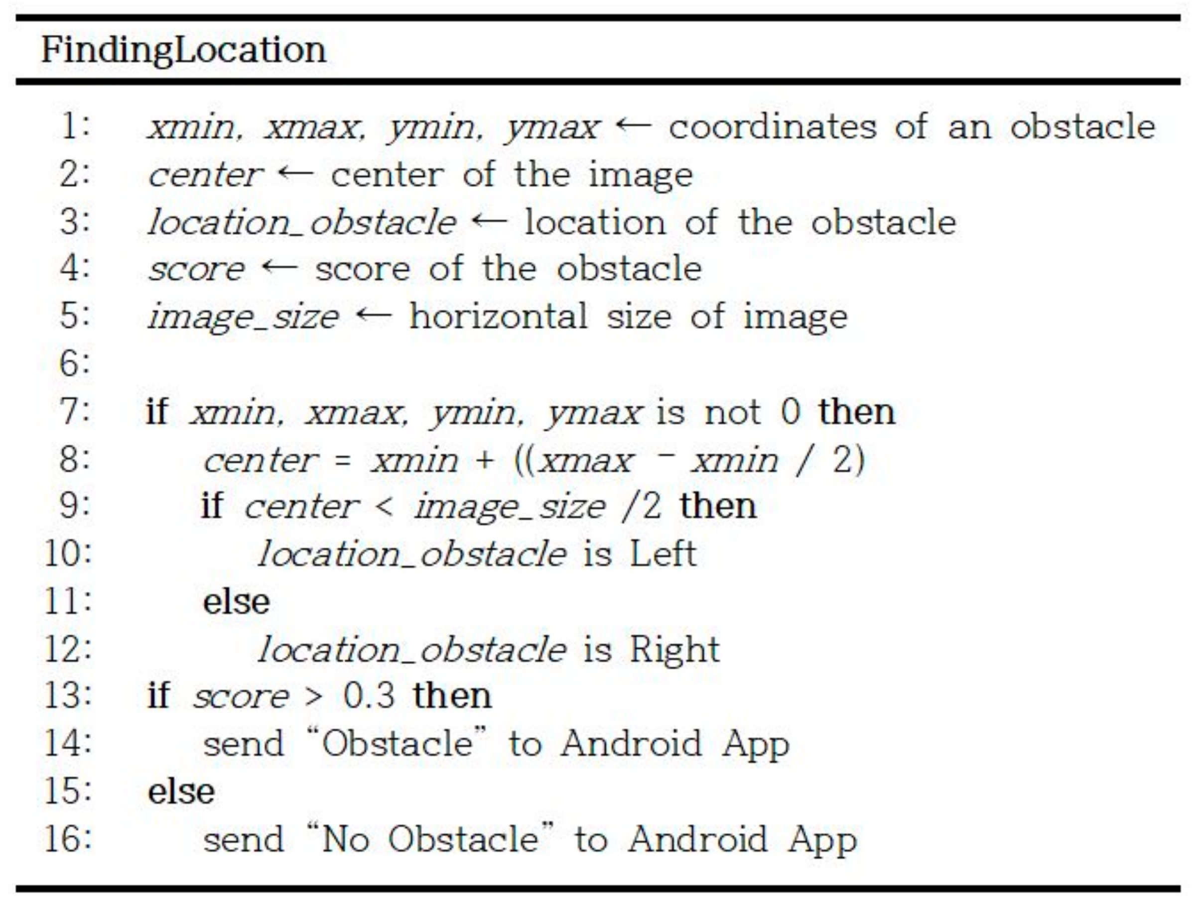
Figure 4 shows the algorithm for finding the location of an obstacle once an obstacle has been detected. Once the obstacle has been recognized, the coordinates can be obtained using the bounding box already added to the image. We could get xmin, xmax, ymin, and ymax, which indicated each vertex of the box. If any of the values were not 0 in an image, it meant that there was an obstacle. Therefore, the center, or the horizontal middle value of the box, could be obtained. If this center value was less than half of the total image size, location_obstacle was left; otherwise, it was right. The coordinates result was sent to the Android app to monitor the obstacle, but only when the threshold was above 0.3. By default, the Google Object Detection API was set to a threshold of 0.2, so it would recognize an object and draw a box only if the score was greater than 0.2. We used a threshold value of 0.3 because the default threshold was too low to recognize obstacles. It could be considered that an obstacle was typically recognized only when the recognition score of the Google Object Detection API was 0.3 or higher.
4.3. Voice Guidance in Client
The results processed by the server were delivered to assist the client immediately. Figure 5 shows how each case is handled from previous recognition results from the server, where 1 is for no crosswalk light, 2 is for a flashing light, 3 is for a red light, and 4 is for a green light. If the same result was received by the client, the voice guidance would not be played because it could be considered that the traffic signal had not yet changed. The voice guidance played only when the receiving result changed. For example, if the red result was received, and then the green result was received, a client could play “green.wav.”
5. Implementation Results and Performance Evaluation
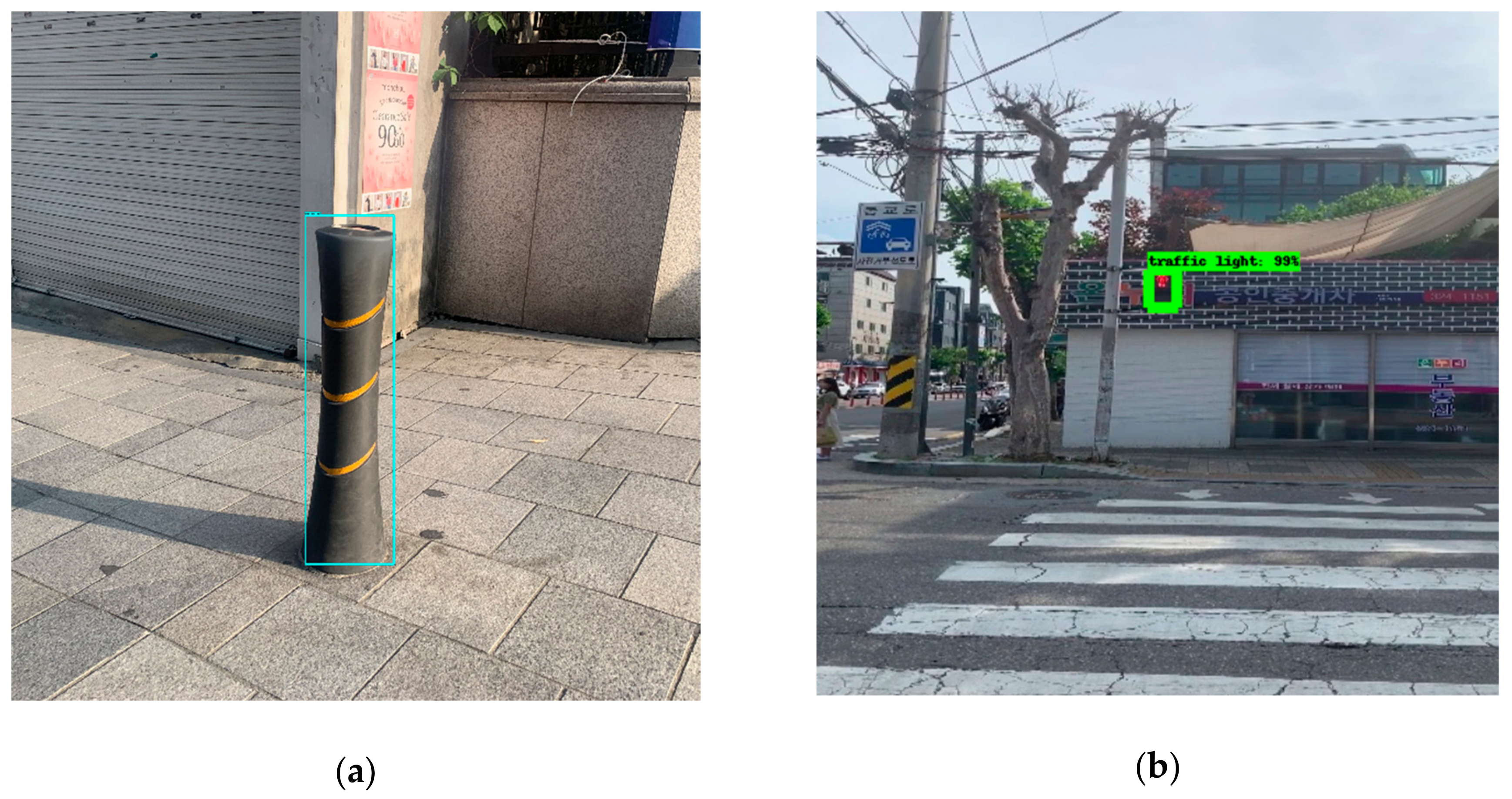
In this section, we describe the performance evaluation of our proposed system, which included the performance of bollard detection using various object detection models, and the performance of the discrimination between crosswalk lights. Moments of recognition of the obstacles are also shown in Figure 6 as they would appear on the display screens of clients. To evaluate our system accurately, we used the images for the performance evaluation, which were taken at various locations, angles, and times of day and night. These images were different than the image data that was used with the training model.
5.1. Implementation Results
This section describes the results of the display screens when recognizing crosswalk lights or bollards. Figure 6 shows the moments of recognition for two different obstacles. Figure 6a shows a screen that recognizes a bollard, while Figure 6b shows a screen that recognizes a crosswalk light. Both the bollard and crosswalk light were from verification data taken elsewhere and not from the images used for training. Each image that was sent by the Raspberry Pi camera module was successfully recognized in real time by the server. The obstacle then appeared in the bounding box. In addition, the position of the obstacles could be determined by the coordinate values.
5.2. Performance Evaluation
This section compares the obstacle recognition models we used and presents their performance evaluations. First, we retrained the two pre-trained models (SSD MobileNet and Faster R-CNN), using the same training data for each of them. Table 2 shows the performance results of the two models when using the same verification images. The speed of the models and the COCO mean average precision (mAP) are both explained on the Google Object Detection site [12]. It stated that the speed of the Faster R-CNN was greater than that of the SSD MobileNet model. Moreover, the COCO mAP was smaller. For the verification image, images taken from different locations were used. A total of 1000 images were used and they consisted of 500 bollards and 500 crosswalk lights. The SSD MobileNet could be used for minor computing power, but the accuracy of detecting obstacles was only 79.6%. The Faster R-CNN, in contrast, had a higher recognition rate, accurately recognizing 95.1% of obstacles.
Table 3 shows the accuracy measurement for the crosswalk safety guidance. The data used in this test were taken during two time periods (daytime and nighttime). In addition, the images were classified into three categories: flashing, green, and red. We photographed them for five seconds each. The algorithm confirmed whether the client could safely cross the crosswalk or not. In Table 3, more than 80% of the images distinguished between flashing, green, and red lights during the daytime. However, the algorithm that determined whether a client could safely cross the crosswalk had a significantly lower performance rate during the nighttime, which could be due to the light blur effect caused by the lighting.
Predicting and monitoring the state of a crosswalk light is very important, because any incorrect guidance could impair the safety of the client and cause harm. Therefore, we reanalyzed the low guidance results listed in Table 3. When the crosswalk light was red, guidance for crossing the crosswalk was 0%. This indicated that the probability of guidance results that posed a great risk to the client were close to 0%. However, we are still in the process of developing a filtering algorithm because we know that the system must have higher accuracy for the safest crosswalk guidance possible.
Table 4 shows the accuracy measurements of the bollard location finding algorithm when determining the position of obstacles when a bollard is recognized. These results were measured using validation images in which one bollard was recognized. The data consisted of images from both day and night. In both cases, when a bollard was recognized in an image, the system could guide the client by informing the client about the location of the bollard.
6. Conclusions
In this study, we proposed recognition software for crossing lights and bollards, along with a hardware system. The proposed system did not need to be built, nor was a client required to wear any expensive equipment. Additionally, it was possible to recognize the two aforementioned obstacles by using a video input device, namely, a single camera, rather than several types of sensor, as necessitated by previous systems.
We initially used pre-trained models that recognized the two obstacles. We retrained the SSD MobileNet and Faster R-CNN models using the Google Object Detection API. The client had a Raspberry Pi and an Android app, and the camera module of the Raspberry Pi streamed images in real time. Then, the obstacle recognition model in the server recognized obstacles in the images. If the obstacle was a crosswalk light, it used the crosswalk discrimination module to determine if it was a red, green, or flashing light. In the case of a bollard, it identified the position of the bollard in the image and returned the location information. The results were passed back to the Raspberry Pi and Android app via the network module and guided the client by voice guidance playback to safely overcome the obstacle.
In this study, we revealed moments of obstacle recognition displayed on obstacle detection screens from our system. We also compared the performance of the SSD MobileNet to that of the Faster R-CNN model and found that the Faster R-CNN recognition results were significantly better. The performance of the crosswalk safety guidance algorithm was approximately 80% during the daytime. This result seemed somewhat low, but the result of risking the safety of the client among the mismatched results was 0%. The currently low results could be improved and resolved in the future by improving the current algorithms.
In the future, we need to extend this system in many ways. First, the system was implemented on the premise that one obstacle was recognized in one image. We are devising how to calculate and guide directionality when several obstacles are recognized in an image. Second, the algorithms of the system need to be improved. The system must guide the client even more safely when using the crosswalk safety guidance algorithm. With these types of improvements to our current system on the horizon, the potential for the blind walking outdoors independently is great.
Author Contributions
Software, S.O. and H.P.; Supervision, J.L. All authors have read and agreed to the published version of the manuscript.
Funding
This research was supported by the National Research Foundation of Korea (NRF) funded by the MSIT (NRF-2018R1A4A1025559).
Conflicts of Interest
The authors declare no conflict of interest.
References
- The Kyunghyang Shinmun. Neglected Disability Safety. Available online: http://news.khan.co.kr/kh_news/khan_art_view.html?artid=201907220600005&code=940601 (accessed on 22 July 2019).
- Bourne, R.; Flaxman, S.; Braithwaite, T.; Cicinelli, M.; Das, A.; Jonas, J.; Taylor, H. Magnitude, temporal trends, and projections of the global prevalence of blindness and distance and near vision impairment: A systematic review and meta-analysis. J. Lancet Glob. Health 2017, 5, 888–897. [Google Scholar] [CrossRef] [Green Version]
- Welfarenews. The Installation Rate of the Audio Signal for the Visually Impaired is only 57%. Available online: http://www.welfarenews.net/news/articleView.html?idxno=69527 (accessed on 19 June 2019).
- Liu, W.; Anguelov, D.; Erhan, D.; Szegedy, C.; Reed, S.; Fu, C.Y.; Berg, A.C. SSD: Single Shot MultiBox Detector. In Proceedings of the European Conference on Computer Vision, Amsterdam, The Netherlands, 8–16 October 2016; pp. 21–37. [Google Scholar]
- Ren, S.; He, K.; Girshick, R.; Sun, J. Faster R-CNN: Towards Real-Time Object Detection with Region Proposal Networks. IEEE Trans. Pattern Anal. Mach. Intell. 2017, 39, 1137–1149. [Google Scholar] [CrossRef] [PubMed] [Green Version]
- Park, H.; Won, H.; Ou, S.; Lee, J. Implementation of Crosswalk Lights Recognition System for the Blind’s Safety. In Proceedings of the 2019 IEEE Eurasia Conference on IOT, Communication and Engineering (IEEE ECICE 2019), Yunlin, Taiwan, 3–6 October 2019. [Google Scholar]
- Shoval, S.; Borenstein, J.; Koren, Y. Mobile robot obstacle avoidance in a computerized travel aid for the blind. In Proceedings of the 1994 IEEE International Conference on Robotics and Automation, San Diego, CA, USA, 8–13 May 1994; pp. 2023–2029. [Google Scholar]
- Hub, A.; Diepstraten, J.; Ertl, T. Design and development of an indoor navigation and object identification system for the blind. In Proceedings of the 6th international ACM SIGACCESS conference on Computers and accessibility, Atlanta, GA, USA, 18–20 October 2004; pp. 147–152. [Google Scholar]
- Sainarayanan, G.; Nagarajan, R.; Yaacob, S. Fuzzy image processing scheme for autonomous navigation of human blind. Appl. Soft Comput. 2007, 7, 257–264. [Google Scholar] [CrossRef]
- Bousbia-Salah, M.; Bettayeb, M.; Larbi, A. A Navigation Aid for Blind People. J. Intell. Robot. Syst. 2011, 64, 387–400. [Google Scholar] [CrossRef]
- Nassih, M.; Cherradi, I.; Maghous, Y.; Ouriaghli, B.; Salih-Alj, Y. Obstacles Recognition System for the Blind People Using RFID. In Proceedings of the Next Generation Mobile Applications, Services and Technologies (NGMAST), Paris, France, 12–14 September 2012. [Google Scholar]
- Google Object Detection API. Available online: https://github.com/tensorflow/models/blob/master/research/object_detection/ (accessed on 25 October 2019).
- Abadi, M.; Barham, P.; Chen, J.; Chen, Z.; Davis, A.; Dean, J.; Zheng, X. TensorFlow: A system for large-scale machine learning. In Proceedings of the 12th USENIX Symposium on Operating Systems Design and Implementation, Savannah, GA, USA, 2–4 November 2016; pp. 265–283. [Google Scholar]
- Tzutalin. LabelImg. Available online: https://github.com/tzutalin/labelImg (accessed on 25 October 2019).
- Redmon, J.; Divvala, S.; Girshick, R.; Farhadi, A. You Only Look Once: Unified, Real-Time Object Detection. In Proceedings of the IEEE Conference on Computer Vision and Pattern Recognition (CVRP), Las Vegas, NV, USA, 27–30 June 2016; pp. 779–788. [Google Scholar]
Figure 1.
Architecture of obstacle recognition system.

Figure 2.
Algorithm for crosswalk discrimination (color identification).

Figure 3.
Algorithm for crosswalk safety guidance.

Figure 4.
Algorithm for finding location.

Figure 5.
Algorithm for voice guidance determination of Raspberry Pi.

Figure 6.
Display screens recognizing obstacles utilizing the proposed model: (a) bollard detection; (b) crosswalk light detection.
Figure 6.
Display screens recognizing obstacles utilizing the proposed model: (a) bollard detection; (b) crosswalk light detection.


Table 1.
Comparison between related works and the proposed system.
| Navigation Aid for Blind [10] | System with Radio-Frequency Identification (RFID) [11] | Proposed Obstacle Recognition System | |
|---|---|---|---|
| Sensors Used | Several ultrasonic | Several RFID | One camera |
| Obstacle type recognition | Impossible | Possible | Possible |
Table 2.
Comparison of obstacle recognition models.
| Model | Speed (ms) | Common Objects in Context Mean Average Precision (COCO mAP) | Accuracy |
|---|---|---|---|
| Single shot multibox detector (SSD) MobileNet | 30 | 21 | 79.6% |
| Faster region-convolutional neural network (R-CNN) | 106 | 32 | 95.1% |
Table 3.
Accuracy measurement for crosswalk safety guidance.
| Flashing | Green | Red | |
|---|---|---|---|
| Day | 82% | 84% | 80% |
| Night | 42% | 68% | 52% |
Table 4.
Accuracy measurement for bollard location finding.
| Bollard | |
|---|---|
| Day | 100% |
| Night | 100% |
© 2019 by the authors. Licensee MDPI, Basel, Switzerland. This article is an open access article distributed under the terms and conditions of the Creative Commons Attribution (CC BY) license (http://creativecommons.org/licenses/by/4.0/).
Share and Cite
MDPI and ACS Style
Ou, S.; Park, H.; Lee, J. Implementation of an Obstacle Recognition System for the Blind. Appl. Sci. 2020, 10, 282. https://doi.org/10.3390/app10010282
AMA Style
Ou S, Park H, Lee J. Implementation of an Obstacle Recognition System for the Blind. Applied Sciences. 2020; 10(1):282. https://doi.org/10.3390/app10010282
Chicago/Turabian StyleOu, Soobin, Huijin Park, and Jongwoo Lee. 2020. "Implementation of an Obstacle Recognition System for the Blind" Applied Sciences 10, no. 1: 282. https://doi.org/10.3390/app10010282
Note that from the first issue of 2016, this journal uses article numbers instead of page numbers. See further details here.